

 Manufacturers
AAVID, THERMAL DIVISION OF BOYD CORP 78010

Description
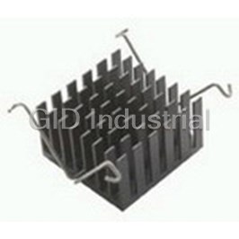
Heat Sink Passive TO-220 Extruded SMD 1.89C/W
78010
Part Number
78010
Price
Request Quote
Manufacturer
AAVID, THERMAL DIVISION OF BOYD CORP
Lead Time
Request Quote
Category
Thermal Management » Heat Sink
Specifications
Manufacturer
Aavid, Thermal Division of Boyd Corp
Manufacturers Part #
78010
Lead Time
12 Week Lead Time
Industry Aliases
78010
Sub-Category
Thermal Management Heat Sinks
Factory Pack Quantity
1
Datasheet


Extracted Text
Table of Contents How to Use this Catalog ......................................................................................................................................................................................................... 2 TM How to Order The Max Clip System ............................................................................................................................................................................... 3 TM The Max Clip System Advantages .................................................................................................................................................................................. 4 The Max Extrusion Index ................................................................................................................................................................................................. 5–6 The Max Clip System™ Profiles ..................................................................................................................................................................................... 7–22 Single Mounting Surface ............................................................................................................................................................................... 7–12 Dual Mounting Surface ............................................................................................................................................................................... 13–15 Max Heat Connector .................................................................................................................................................................................... 16–18 Single Mounting Surface with Flatback ......................................................................................................................................................... 19 U-Channel/Multiple Screw Boss ....................................................................................................................................................................... 20 Potential Max Profiles ................................................................................................................................................................................... 21–22 The Max Clip System™ Clip Index ............................................................................................................................................................................. 23–25 The Max Clip System™ Clips ....................................................................................................................................................................................... 26–28 Standard Clips ................................................................................................................................................................................................. 26–27 U-Clips ....................................................................................................................................................................................................................... 28 Max Clip Assembly Ideas ..................................................................................................................................................................................................... 29 Semi-Automated Assembly ......................................................................................................................................................................................... 30–31 Chief Extrusion Profiles ................................................................................................................................................................................................. 32–33 Solderable Pins ........................................................................................................................................................................................................................ 34 Thermal Performance ........................................................................................................................................................................................................... 35 Shock & Vibration Testing .................................................................................................................................................................................................... 36 Extrusion Standard Tolerances .......................................................................................................................................................................................... 37 THE MAX CLIP SYSTEM™ CLIP SOLUTIONS ONLY LIMITED BY THE IMAGINATION TM The Max Clip System is approved by leading providers of power semiconductors, including: Advanced Power Technology, International Rectifier, STMicroelectronics, and IXYS APT Advanced Power Technologies manufactures high power, high voltage, high performance power semiconductors for the internet, computers and high capacity mass storage products, wireless cellular base stations for telecommunications, advanced industrial, military and space applications. International Rectifier is a global supplier of power semiconductors for power conversion. Its Hexfet MOSFETs are used in anti-lock braking and fuel injection systems, disk drives, printers, video cameras, power tools, electronic lighting ballasts, industrial test equipment, telephone networks/modems, and satellites. STMicroelectronics is one of the world’s leading suppliers of semiconductor integrated circuits and discrete devices. STM is especially focused on MPEG2 decoder ICs, smartcard MCUs, special automotive ICs and EPROM memories. IXYS Corporation designs, develops and markets power semiconductors for controlling energy in motor drives, power conversion (UPS uninterruptible power supplies and SMPS switch mode power supplies), and medical electronics. IXYS focuses on high power semiconductors processing over 500 watts of power. PLEASE NOTE: Our customers are reminded that they bear the responsibility for testing Aavid Thermalloy products for proposed use. Any information furnished by Aavid Thermalloy is believed to be accurate and reliable, but our customers must bear all responsibility for use and applications of Aavid Thermalloy products. All Aavid Thermalloy products are sold subject to the Aavid Domestic Terms and Conditions of Sale in effect, a copy of which shall be furnished upon request (8911A). Copyright © Aavid Thermalloy, LLC, January 2005. All icons, drawings, illustrations, and trademarks are the property of Aavid Thermalloy, LLC and may not be reproduced without express written permission. (1/2005) USA Tel: +1 (603) 224-9988 email: info@aavid.com AMERICA ASIA Singapore Tel: +65 6362 8388 email: sales@aavid.com.sg Taiwan Tel: +886(2) 2698-9888 email: sales@aavid.com.tw Italy Tel: +39 051 764011 email: sales.it@aavid.com EUROPE 1 www.aavidthermalloy.com United Kingdom Tel: +44 1793 401400 email: sales.uk@aavid.com TABLE OF CONTENTS How to Use this Catalog Max Extrusions Base extrusion part number Thermal resistance in For ordering information see page 3 natural (θn) and forced (θf ) convection environments See notes on page 5 for thermal resistance definitions Extrusion weight kilograms per meter kg/m: 1.38 • θn = 2.46 ºC/W • θf = 0.65 ºC/W 78015 • One slot for vertical 30.00 mounting to board (1.181) ş2.79 18.01 (0.709) (0.110) 2.35 (0.092) Mechanical drawing illustrating cross section of an extrusion Bullet illustrates Dimensions are mm (inches) differentiating features 45.01 for each Max profile (1.772) 29.90 (1.180) 4.78 (0.188) M3 3.00 (0.118) Max Clips Clip part number For ordering information see page 3 Clip force equation (clip width) x (thickness) = force in newtons Width Thickness Force Max03-H 18 mm x 0.6 = 80 N Clip width (not shown in profile view below) T0247/Max247 Mechanical drawing showing T0247J profile of clip, extrusion and device with contact point dimensions 14.70 (0.580) To select a clip appropriate for the device cooled and the selected profile see the Clip Index on pages 23–25. USA Tel: +1 (603) 224-9988 email: info@aavid.com Singapore Tel: +65 6362 8388 email: sales@aavid.com.sg AMERICA ASIA Taiwan Tel: +886(2) 2698-9888 email: sales@aavid.com.tw Italy Tel: +39 051 764011 email: sales.it@aavid.com EUROPE 2 United Kingdom Tel: +44 1793 401400 email: sales.uk@aavid.com www.aavidthermalloy.com HOW TO USE THIS CATALOG How to Order TM How to Order The Max Clip System General Information: Extrusions are available in standard bar lengths of 2.5 meters/8.2 feet. Extrusions are unfinished and may be ordered with a black anodize finish. The standard tolerance of all cut to length extrusions is ±0.015 inches. Max Extrusion Profiles Extrusions are ordered using a 12 digit part number as shown below. 78040 X X XXXXX Custom cut length Specified to 3 decimal places i.e. 1.200 inches = 01200 For cut length options 1 and 2 use 5 zeros Finish U = Unfinished B = Black anodize Cutting options 1 = No cut (full length bar) 2 = Cut in half (two equal lengths) 3 = Cut to custom length specified using digits 8-12 Extrusion profile base part number Max Clips Clips are ordered separately using the part number shown in the mechanical drawing header information. See How to Use this Catalog on page 2. Potential Max Profiles TM The Max Clip System is only limited by the imagination. For custom solutions or more information on the Potential Max Profiles listed on pages 21 and 22, please contact your local sales representative. USA Tel: +1 (603) 224-9988 email: info@aavid.com AMERICA ASIA Singapore Tel: +65 6362 8388 email: sales@aavid.com.sg Taiwan Tel: +886(2) 2698-9888 email: sales@aavid.com.tw Italy Tel: +39 051 764011 email: sales.it@aavid.com EUROPE 3 www.aavidthermalloy.com United Kingdom Tel: +44 1793 401400 email: sales.uk@aavid.com ORDERING INFORMATION TM The Max Clip System Advantages TM The Max Clip System MINIMIZE LABOR...MAXIMIZE PERFORMANCE TM The Max Clip System for discrete power semiconductors is a high performance, low cost thermal solution that eliminates mounting holes, screws, rivets, and the thermal inefficiency associated with using loose hardware to attach components to a heat sink. This quick, robust attachment method saves on labor and hardware costs while increasing performance and design flexibility. TM The Max Clip System is also the most effective system for mounting power devices in packages that have no mounting holes. Max Clips apply consistent optimum pressure at the center of the semicon- ductor, improving contact with the heat sink for better thermal performance and maximum compo- nent reliability. Aavid offers approximately 50 extrusion profiles that accept over 20 different Max Clips TM to suit your application. The Max Clip System is designed to accommodate a variety of semiconductor packages including TO-220, TO-218, TO-247, TO-3P, and packages without mounting holes like TO-262, TO-273, TO-274, and TO-251. TM Features and Benefits of The Max Clip System include: • Optimizes thermal management of power transistors • Provides mounting for discrete power devices with or without mounting holes • Reduce labor costs by eliminating the need for drilled or tapped holes in heat sinks • Allows flexibility for moving or changing devices • Provides consistent mounting force for reduced thermal resistivity (over lifetime) TM • Assembly costs using The Max Clip System are lower than with conventional hardware such as screws/nuts The Max Clip System™ provides ideal product lifetime contact to the center of the device package resulting in even force across the interface material. Max Clips maintain a constant assembly force even when interface material deteriorates over time. With conventional nuts, bolts and rivets mounting force is set at the time of assembly and can lessen over the product’s service life with changes in interface material thickness. Nuts and bolts also impart force at one end of the package creating uneven pressure over the length of the device, actually creating thermal inefficiency. See Figure 1. Figure 1 Poor Contact Maximum Contact Max Clip Tightly Torqued Air Gap USA Tel: +1 (603) 224-9988 email: info@aavid.com Singapore Tel: +65 6362 8388 email: sales@aavid.com.sg AMERICA ASIA Taiwan Tel: +886(2) 2698-9888 email: sales@aavid.com.tw Italy Tel: +39 051 764011 email: sales.it@aavid.com EUROPE 4 United Kingdom Tel: +44 1793 401400 email: sales.uk@aavid.com www.aavidthermalloy.com TM THE MAX CLIP SYSTEM ADVANTAGES Max Extrusion Index Part Page Weight Weight Width Height Perimeter θn θfType Number kg/m lb/ft mm (in) mm (in) mm (in) 78010 7 2.48 1.663 34.00 (1.338) 75.00 (2.953) 948.99 (37.362) 1.45 0.39 1 78015 7 1.38 0.925 27.00 (1.063) 50.02 (1.969) 499.99 (19.685) 2.46 0.65 1 78020 14 1.23 0.825 30.00 (1.181) 47.20 (1.850) 372.99 (14.685) 3.02 0.84 2 78025 12 0.99 0.664 39.00 (1.535) 31.48 (1.239) 310.01 (12.205) 3.10 1.02 1 78030 20 3.42 2.293 73.54 (2.895) 60.00 (2.362) 1002.00 (39.449) 1.10 0.36 5 78035 8 2.53 1.697 74.50 (2.933) 40.01 (1.575) 808.99 (31.850) 1.23 0.42 1 78040 14 4.64 3.111 102.00 (4.016) 71.20 (2.803) 1410.00 (55.512) 0.81 0.28 2 78045 8 1.59 1.066 40.00 (1.575) 40.00 (1.575) 475.99 (18.740) 2.12 0.64 1 78050 21 3.47 2.327 82.00 (3.228) 50.00 (1.968) 1161.62 (45.733) 0.63 0.25 6 78060 9 1.18 0.791 30.00 (1.181) 45.01 (1.772) 424.99 (16.732) 2.33 0.76 1 78070 13 2.57 1.723 40.00 (1.575) 75.00 (2.953) 783.00 (30.827) 1.55 0.41 2 78075 9 1.64 1.100 38.00 (1.496) 54.00 (2.126) 581.99 (22.913) 1.71 0.57 1 78080 7 1.74 1.167 27.00 (1.063) 60.00 (2.362) 604.01 (23.780) 2.27 0.55 1 78085 16 1.32 0.885 28.70 (1.230) 41.00 (1.614) 142.01 (5.591) - - 4 78090 16 0.84 0.563 17.00 (0.669) 37.28 (1.468) 143.00 (5.630) - - 4 78095 18 1.89 1.267 29.00 (1.142) 36.80 (1.449) 140.00 (5.512) - - 4 78105 20 6.10 4.090 206.00 (8.110) 90.00 (3.543) 1526.99 (60.118) 0.55 0.27 5 78110 20 5.13 3.440 155.00 (6.102) 85.00 (3.346) 1291.99 (50.866) 0.70 0.25 5 78185 18 2.14 1.435 40.00 (1.575) 57.00 (2.244) 246.98 (9.724) - - 4 78190 10 2.37 1.589 58.00 (2.283) 66.50 (2.618) 648.00 (25.512) 1.25 0.50 1 78195 11 1.10 0.738 34.00 (1.338) 36.60 (1.441) 313.99 (12.362) 2.70 0.93 1 78200 18 0.89 0.597 25.00 (0.984) 35.98 (1.416) 181.00 (7.126) - - 4 78205 13 1.57 1.053 30.00 (1.181) 57.00 (2.244) 437.99 17.244) 2.42 0.75 2 78215 8 1.32 0.885 61.21 (2.410) 28.00 (1.102) 386.99 (15.236) 2.50 0.85 1 78220 13 1.66 1.113 30.00 (1.181) 60.00 (2.362) 488.01 (19.213) 2.49 0.74 2 78225 17 1.75 1.173 23.00 (0.905) 45.00 (1.772) 178.00 (7.008) - - 4 78230 18 1.39 0.932 28.00 (1.102) 45.00 (1.772) 211.98 (8.346) - - 4 78245 7 1.67 1.120 27.00 (1.063) 60.00 (2.362) 596.01 (23.465) 2.29 0.56 1 78250 14 2.15 1.442 60.00 (2.362) 56.00 (2.205) 632.99 (24.921) 1.42 0.52 2 78255 17 0.68 0.456 27.00 (1.063) 27.00 (1.063) 154.00 (6.063) 3.43 1.59 4 78260 19 0.12 0.080 10.50 (0.413) 11.50 (0.453) 59.99 (2.362) - - 3 78265 12 0.48 0.322 22.00 (0.866) 28.50 (1.122) 199.99 (7.874) 4.12 1.68 1 78270 18 0.95 0.637 27.00 (1.063) 29.50 (1.161) 156.99 (6.181) 3.43 1.59 4 78275 12 1.78 1.194 31.75 (1.250) 58.70 (2.311) 483.00 (19.016) 2.35 0.67 1 78280 18 0.75 0.503 22.98 (0.905) 38.00 (1.496) 165.98 (6.535) 3.11 1.50 4 78285 10 2.41 1.616 34.00 (1.338) 75.00 (2.953) 908.98 (35.787) 1.47 0.40 1 78290 21 9.64 6.464 240.80 (9.480) 77.00 (3.031) 1362.43 (53.639) - - 6 78295 11 2.18 1.462 35.00 (1.378) 60.00 (2.362) 688.00 (27.087) 1.67 0.47 1 78300 21 4.51 3.024 165.00 (6.496) 62.00 (2.441) 499.82 (19.678) - - 6 78305 21 1.62 1.086 120.76 (4.754) - 659.10 (25.949) - - 6 78310 21 1.50 1.006 - - 628.01 (24.725) - - 6 78315 9 3.14 2.106 48.00 (1.890) 80.00 (3.150) 1010.00 (39.764) 1.06 0.34 1 78335 19 0.31 0.208 30.10 (1.185) 12.50 (0.492) 138.98 (5.472) 6.34 2.38 3 78345 15 2.21 1.482 68.00 (2.677) 39.00 (1.535) 670.00 (26.378) 1.64 0.49 2 78350 9 3.45 2.313 49.50 (1.949) 85.50 (3.366) 1153.00 (45.394) 0.93 0.29 1 78355 12 1.15 0.771 32.30 (1.272) 49.00 (1.929) 456.99 (17.992) 2.34 0.76 1 78360 15 3.29 2.206 108.00 (4.252) 39.00 (1.535) 1054.98 (41.535) 1.18 0.41 2 78370 21 0.55 0.372 29.97 (1.180) 29.21 (1.150) 183.28 (7.216) - - 6 78375 10 1.49 0.999 54.50 (2.146) 38.60 (1.520) 445.00 (17.520) 1.82 0.78 1 78380 21 16.17 10.843 241.48 (9.507) 140.00 (5.512) 3230.29 (127.177) - - 6 78385 21 4.27 2.863 240.00 (9.449) 60.00 (2.362) 914.19 (35.992) - - 6 78390 20 6.02 4.037 179.98 (7.086) 51.00 (2.008) 1737.00 (68.386) 0.44 0.19 5 Notes: Type definitions: θn: Thermal resistance—Natural convection. Length = 150 mm 1= Single Mounting Surface Style θf: Thermal resistance—Forced convection. Air Speed Inlet Tunnel = 2 2= Dual Mounting Surface Style m/s 3= Single Mounting Surface with Flatback Style Black anodized or unfinished 4= Max Heat Connector Style Ambient T = 25 ºC 5= U-Channel/Multiple Screw Boss Style Heat sink T = 100 ºC 6= Potential Max Profiles USA Tel: +1 (603) 224-9988 email: info@aavid.com AMERICA ASIA Singapore Tel: +65 6362 8388 email: sales@aavid.com.sg Taiwan Tel: +886(2) 2698-9888 email: sales@aavid.com.tw Italy Tel: +39 051 764011 email: sales.it@aavid.com EUROPE 5 www.aavidthermalloy.com United Kingdom Tel: +44 1793 401400 email: sales.uk@aavid.com MAX EXTRUSION INDEX Max Extrusion Index Part Page Weight Weight Width Height Perimeter θn θfType Number kg/m lb/ft mm (in) mm (in) mm (in) 78405 11 1.36 0.912 49.00 (1.929) 40.00 (1.575) 554.99 (21.850) 1.32 0.56 1 81400 20 5.51 3.695 124.16 (3.160) 80.26 (3.160) 1065.50 (41.949) 0.98 0.38 5 82005 15 2.60 1.743 71.12 (2.800) 38.81 (1.528) 610.69 (24.043) - - 2 82870 10 3.09 2.072 35.00 (1.378) 90.10 (3.547) 1062.99 (41.850) 1.35 0.32 1 82875 16 0.95 0.637 23.00 (0.905) 36.90 (1.453) 127.99 (5.039) - - 4 82880 17 1.72 1.153 30.00 (1.181) 49.70 (1.957) 226.99 (8.937) - - 4 82885 16 0.85 0.570 21.40 (0.842) 34.00 (1.338) 121.99 (4.803) - - 4 82890 16 1.40 0.939 15.00 (0.590) 56.60 (2.228) 159.00 (6.260) - - 4 82895 19 1.08 0.724 22.00 (0.866) 48.00 (1.890) 248.99 (9.803) 3.42 1.57 3 82900 16 1.18 0.791 28.00 (1.102) 35.00 (1.378) 170.99 (6.732) - - 4 82905 14 2.02 1.355 49.50 (1.949) 50.00 (1.968) 672.00 (26.457) 1.92 0.57 2 82910 8 2.45 1.643 50.00 (1.968) 69.00 (2.716) 800.98 (31.535) 1.28 0.44 1 82920 10 2.38 1.596 35.00 (1.378) 75.00 (2.953) 899.00 (35.394) 1.56 0.41 1 82925 17 1.69 1.133 38.00 (1.496) 30.00 (1.181) 180.00 (7.087) - - 4 82930 8 2.04 1.368 50.00 (1.968) 47.00 (1.850) 532.99 (20.984) 1.71 0.58 1 82935 7 2.51 1.683 34.00 (1.338) 75.00 (2.953) 878.00 (34.567) - - 1 82940 11 1.14 0.764 55.00 (2.165) 43.00 (1.693) 280.00 (11.024) 1.96 1.00 1 82945 17 1.89 1.267 27.00 (1.063) 38.00 (1.496) 146.98 (5.787) - - 4 82950 8 5.52 3.701 45.00 (1.772) 120.00 (4.724) 1162.99 (45.787) - - 1 82955 13 1.41 0.945 30.00 (1.181) 49.80 (1.961) 378.00 (14.882) 2.99 0.83 2 82960 20 2.75 1.844 73.50 (2.894) 50.00 (1.968) 721.00 (28.386) 1.30 0.46 5 82965 19 0.90 0.604 15.00 (0.590) 54.00 (2.126) 264.00 (10.394) 3.43 1.12 3 82970 19 0.41 0.275 33.00 (1.300) 21.00 (0.827) 186.99 (7.362) 4.38 2.10 3 82975 9 0.74 0.496 25.00 (0.984) 37.50 (1.476) - 3.31 1.55 1 82980 17 0.81 0.543 27.00 (1.063) 27.00 (1.063) 135.00 (5.315) - - 4 82985 14 2.24 1.502 55.00 (2.165) 65.40 (2.575) - 1.52 0.62 2 82990 9 1.18 0.791 35.00 (1.378) 37.50 (1.476) - 2.49 0.95 1 83000 11 1.45 0.972 38.00 (1.496) 54.00 (2.126) 381.00 (15.000) 1.83 0.77 1 83005 7 1.73 1.160 27.00 (1.063) 60.00 (2.362) 581.99 (22.913) 2.30 0.59 1 83010 14 4.36 2.924 50.00 (1.968) 73.00 (2.874) - 1.17 0.35 2 83015 11 1.49 0.999 46.90 (1.846) 51.60 (2.031) - 1.73 0.69 1 83020 12 3.57 2.394 75.00 (2.953) 50.00 (1.968) - - - 1 0SA24 21 - - - - - - 6 0SA55 21 - - - - - - 6 0SA61 21 - - - - - - 6 0S567 21 - - - - - - 6 0SA69 21 - - - - - - 6 0SA74 21 - - - - - - 6 0SA79 22 - - - - - - 6 0SA80 22 - - - - - - 6 0SY94 22 - - - - - - 6 BS014 22 - - - - - - 6 BS034 22 - - - - - - 6 BS060 22 - - - - - - 6 BS070 22 - - - - - - 6 BS093 22 - - - - - - 6 BS094 22 - - - - - - 6 BS105 22 - - - - - - 6 BS121 22 - - - - - - 6 BS138 22 - - - - - - 6 BS202 22 - - - - - - 6 Notes: Type definitions: θn: Thermal resistance—Natural convection. Length = 150 mm 1= Single Mounting Surface Style θf: Thermal resistance—Forced convection. Air speed inlet Tunnel = 2 2= Dual Mounting Surface Style m/s 3= Single Mounting Surface with Flatback Style Black anodized or unfinished 4= Max Heat Connector Style Ambient T = 25 ºC 5= U-Channel/Multiple Screw Boss Style Heat sink T = 100 ºC 6= Potential Max Profiles USA Tel: +1 (603) 224-9988 email: info@aavid.com Singapore Tel: +65 6362 8388 email: sales@aavid.com.sg AMERICA ASIA Taiwan Tel: +886(2) 2698-9888 email: sales@aavid.com.tw Italy Tel: +39 051 764011 email: sales.it@aavid.com EUROPE 6 United Kingdom Tel: +44 1793 401400 email: sales.uk@aavid.com www.aavidthermalloy.com MAX EXTRUSION INDEX TM The Max Clip System Single Mounting Surface The Single Mounting Surface style provides a flat component mounting surface on one side of the profile. The back side of the extrusion is covered with fins creating additional surface area to aid in cooling. The component retaining clip interlocks between the first and second fin above the flat component mounting surface. kg/m: 1.38 • θn = 2.46 ºC/W • θf = 0.65 ºC/W kg/m: 1.66 • θn = 2.29 ºC/W • θf = 0.56 ºC/W 78015 78245 27.00 27.00 (1.063) 13.50 (1.063) • One slot for vertical • One slot for vertical 4.90 (0.531) (0.193) mounting to board mounting to board 60.00 50.00 (1.969) (2.362) 50.20 (1.976) 25.00 (0.984) 30.00 ş 0.110 (1.181) 2 PL M3 4.50 5.49 (0.177) (0.216) 9.00 7.50 5.54 6.80 M4 (0.354) (0.295) (0.218) (0.268) 18.00 3.00 5.40 (0.709) (0.213) (0.118) kg/m: 1.74 • θn = 2.27 ºC/W • θf = 0.55 ºC/W kg/m: 2.48 • θn = 1.45 ºC/W • θf = 0.39 ºC/W 78080 78010 34.00 27.00 (1.339) 4.52 13.99 (1.063) (0.178) (0.551) • One slot for vertical • One slot for vertical mounting to board mounting to board 60.00 75.00 (2.362) (2.953) 30.70 (1.209) 30.20 (1.189) M3 5.49 (0.216) 4.50 5.00 M4 (0.177) 7.22 (0.197) (0.284) 18.00 9.00 20.01 (0.709) (0.354) (0.788) kg/m: 2.51 • θn = 1.45 ºC/W • θf = 0.39 ºC/W kg/m: 1.73 • θn = 2.30 ºC/W • θf = 0.59 ºC/W 83005 82935 27.00 (1.063) 34.00 10.00 13.50 10.50 (1.339) (0.394) • One slot for vertical • One slot for vertical 8.60 (0.531) (0.413) 14.00 4.77 mounting to board (0.551) (0.187) (0.339) mounting to board 11.40 3.00 (0.449) (0.118) ş 2.80 (0.110) 2PL 60.00 (2.362) 75.00 (2.953) 30.00 (1.181) 6.80 4.50 32.00 (0.268) (0.177) (1.259) 7.75 (0.306) 11.15 5.10 4.50 (0.439) (0.201) (0.177) 6.00 7.50 M3 (0.236) 7.50 M3 (0.295) (0.295) 12.00 12.40 18.00 (0.472) (0.488) (0.709) USA Tel: +1 (603) 224-9988 email: info@aavid.com AMERICA ASIA Singapore Tel: +65 6362 8388 email: sales@aavid.com.sg Taiwan Tel: +886(2) 2698-9888 email: sales@aavid.com.tw Italy Tel: +39 051 764011 email: sales.it@aavid.com EUROPE 7 www.aavidthermalloy.com United Kingdom Tel: +44 1793 401400 email: sales.uk@aavid.com MAX EXTRUSION PROFILES TM The Max Clip System Single Mounting Surface kg/m: 2.45 • θn = 1.28 ºC/W • θf = 0.44 ºC/W kg/m: 5.52 82950 82910 45.00 (1.772) 6.00 • One screw boss for vertical • One screw boss for vertical (0.236) mounting to board mounting to board 50.00 (1.969) 25.00 (0.984) 120.00 104.80 (4.724) 69.00 (4.126) (2.717) 6.00 30.00 (0.236) (1.181) 4.21 22.00 2 PL (0.166) (0.866) 42.00 (1.653) 8.70 (0.342) M3 4.00 (0.157) 8.00 7.60 (0.315) M4 6.00 (0.299) (0.236) 20.00 (0.787) kg/m: 2.04 • θn = 1.71 ºC/W • θf = 0.58 ºC/W kg/m: 1.59 • θn = 2.12 ºC/W • θf = 0.64 ºC/W 82930 78045 • One slot for vertical • One slot for vertical 40.00 50.00 mounting to board mounting to board (1.575) (1.969) 47.00 38.50 (1.850) (1.516) 29.00 30.00 (1.140) (1.181) 4.77 15.00 (0.187) (0.591) M3 4.75 M3 4.00 4.50 (0.187) (0.157) (0.177) 8.00 14.50 (0.314) (0.571) kg/m: 2.53 • θn = 1.23 ºC/W • θf = 0.42 ºC/W kg/m: 1.32 • θn = 2.50 ºC/W • θf = 0.85 ºC/W 78035 78215 • Two slots for vertical • One screw boss for vertical mounting to board mounting to board 61.21 74.50 (2.410) (2.933) 28.00 40.00 (1.102) (1.575) 22.70 30.00 ş 2.79 (0.894) (1.181) (0.110) 4.21 13.00 (0.166) (0.512) 4.77 M3 5.99 4.00 (0.187) (0.236) M3 6.95 (0.157) 41.00 (0.274) 2 PL 8.00 17.30 (0.681) (1.614) (0.315) USA Tel: +1 (603) 224-9988 email: info@aavid.com Singapore Tel: +65 6362 8388 email: sales@aavid.com.sg AMERICA ASIA Taiwan Tel: +886(2) 2698-9888 email: sales@aavid.com.tw Italy Tel: +39 051 764011 email: sales.it@aavid.com EUROPE 8 United Kingdom Tel: +44 1793 401400 email: sales.uk@aavid.com www.aavidthermalloy.com MAX EXTRUSION PROFILES TM The Max Clip System Single Mounting Surface kg/m: 1.64 • θn = 1.71 ºC/W • θf = 0.57 ºC/W kg/m: 1.18 • θn = 2.33 ºC/W • θf = 0.76 ºC/W 78075 78060 • One slot for vertical • One slot for vertical 30.00 38.00 4.22 mounting to board mounting to board (1.496) (1.181) (0.166) ş2.79 18.01 (0.709) (0.110) 5.99 (0.236) 2.35 (0.092) 54.00 45.01 (1.772) (2.126) 29.90 29.87 (1.180) (1.176) 4.78 (0.188) 4.78 (0.188) M3 M3 3.00 3.00 (0.118) (0.118) 16.00 (0.630) kg/m: 3.14 • θn = 1.06 ºC/W • θf = 0.34 ºC/W kg/m: 3.45 • θn = 0.93 ºC/W • θf = 0.29 ºC/W 78350 78315 • One screw boss for vertical 49.50 • One slot for vertical 4.27 ş 2.79 (1.949) (0.166) mounting to board mounting to board (0.110) 6.00 (0.236) 4.22 6.00 (0.166) (0.236) 85.50 80.00 (3.366) (3.150) 30.00 28.20 (1.181) (1.110) 8.38 (0.331) M3 5.99 10.51 M3 7.00 (0.236) (0.414) (0.276) 21.00 (0.827) 13.00 48.00 (0.512) (1.890) kg/m: 1.18 • θn = 2.49 ºC/W • θf = 0.95 ºC/W kg/m:0.74 • θn = 3.31 ºC/W • θf = 1.55 ºC/W 82990 82975 • Two slots for vertical • Two slots for vertical 25.00 mounting to board mounting to board 35.00 (0.984) (1.378) 37.50 37.50 (1.476) 28.50 (1.476) (1.122) 28.50 6.50 (1.122) (0.255) 6.50 (0.255) M3 M3 8.60 3.70 7.40 (0.145) (0.339) (0.291) 3.70 18.60 TYP(2) (0.145) 16.00 (0.732) (0.630) 26.00 (1.024) USA Tel: +1 (603) 224-9988 email: info@aavid.com AMERICA ASIA Singapore Tel: +65 6362 8388 email: sales@aavid.com.sg Taiwan Tel: +886(2) 2698-9888 email: sales@aavid.com.tw Italy Tel: +39 051 764011 email: sales.it@aavid.com EUROPE 9 www.aavidthermalloy.com United Kingdom Tel: +44 1793 401400 email: sales.uk@aavid.com MAX EXTRUSION PROFILES TM The Max Clip System Single Mounting Surface kg/m: 2.37 • θn = 1.25 ºC/W • θf = 0.50 ºC/W kg/m: 1.49 • θn = 1.82 ºC/W • θf = 0.78 ºC/W 78375 78190 • One screw boss for vertical • One screw boss for vertical mounting to board mounting to board 58.00 54.50 (2.283) (2.146) 14.00 4.49 10.54 (0.551) (0.177) (0.415) 10.00 3.00 (0.394) (0.118) M3 8.71 (0.343) 65.80 (2.591) 37.10 38.60 (1.461) (1.520) 28.50 30.75 4.21 6.05 (1.122) (1.211) (0.166) (0.238) 5.99 M3 (0.236) M3 4.22 4.00 (0.157) (0.166) 8.99 5.00 35.50 (0.196) (0.354) (1.398) 10.00 44.00 (0.394) (1.732) kg/m: 2.41 • θn = 1.47 ºC/W • θf = 0.40 ºC/W kg/m: 3.09 • θn = 1.35 ºC/W • θf = 0.32 ºC/W 78285 82870 35.00 • One slot for vertical • One slot for vertical 34.00 (1.378) mounting to board (1.339) mounting to board 18.50 14.00 (0.728) (0.551) M3 14.70 (0.570) 4.77 (0.188) 75.00 90.10 (2.953) (3.547) 30.20 (1.190) 33.10 (1.303) 7.20 (0.283) 7.28 M4 5.00 (0.287) (0.197) 9.00 (0.354) M4 5.99 (0.236) kg/m: 2.38 • θn = 1.56 ºC/W • θf = 0.41 ºC/W 10.00 82920 (0.394) • One slot for vertical 35.00 (1.378) mounting to board 7.50 (0.295) 75.00 (2.953) 32.00 (1.259) 7.50 (0.295) M4 5.99 (0.236) 10.00 (0.394) USA Tel: +1 (603) 224-9988 email: info@aavid.com Singapore Tel: +65 6362 8388 email: sales@aavid.com.sg AMERICA ASIA Taiwan Tel: +886(2) 2698-9888 email: sales@aavid.com.tw Italy Tel: +39 051 764011 email: sales.it@aavid.com EUROPE 10 United Kingdom Tel: +44 1793 401400 email: sales.uk@aavid.com www.aavidthermalloy.com MAX EXTRUSION PROFILES TM The Max Clip System Single Mounting Surface kg/m: 2.18 • θn = 1.67 ºC/W • θf = 0.47 ºC/W kg/m: 1.45 • θn = 1.83 ºC/W • θf = 0.77 ºC/W 78295 83000 • One slot for vertical • Two screw bosses for vertical 38.00 35.00 mounting to board mounting to board (1.495) (1.378) 5.00 28.00 (0.197) (1.102) 4.22 20.00 (0.166) (0.787) 6.00 9.00 (0.236) (0.354) 60.00 (2.362) 54.00 (2.126) 27.80 23.40 (1.094) 4.50 (0.921) (0.177) M4 5.00 M3 7.50 (0.196) 13.00 (0.295) (0.512) 10.00 26.00 (0.394) 15.60 (1.024) (0.614) kg/m: 1.14 • θn = 1.96 ºC/W • θf = 1.00 ºC/W kg/m: 1.36 • θn = 1.32 ºC/W • θf = 0.56 ºC/W 78405 82940 • One screw boss for vertical • One slot for vertical mounting to board mounting to board 49.00 55.00 (2.165) (1.929) 40.00 43.00 (1.575) (1.693) 32.50 (1.279) 22.00 (0.866) 4.22 (0.166) 5.50 6.00 (0.217) (0.236) M3 M3 6.00 3.50 (0.236) (0.138) 7.00 40.00 (0.275) (1.570) kg/m: 1.49 • θn = 1.73 ºC/W • θf = 0.69 ºC/W kg/m: 1.10 • θn = 2.70 ºC/W • θf = 0.93 ºC/W 83015 78195 • One slot for vertical • One screw boss for vertical 46.90 mounting to board mounting to board (1.846) 12.00 34.00 (0.472) (1.339) 36.61 51.60 (1.441) (2.031) 27.10 (1.067) 35.00 ş 2.79 (1.377) (0.110) 7.70 5.99 19.65 (0.303) (0.236) (0.774) M3 4.22 (0.166) 5.00 (0.197) M3 3.00 (0.118) 6.00 (0.236) 12.00 (0.472) USA Tel: +1 (603) 224-9988 email: info@aavid.com AMERICA ASIA Singapore Tel: +65 6362 8388 email: sales@aavid.com.sg Taiwan Tel: +886(2) 2698-9888 email: sales@aavid.com.tw Italy Tel: +39 051 764011 email: sales.it@aavid.com EUROPE 11 www.aavidthermalloy.com United Kingdom Tel: +44 1793 401400 email: sales.uk@aavid.com MAX EXTRUSION PROFILES TM The Max Clip System Single Mounting Surface kg/m: 1.78 • θn = 2.35 ºC/W • θf = 0.67 ºC/W kg/m: 1.15 • θn = 2.34 ºC/W • θf = 0.76 ºC/W 78275 78355 • One screw boss for 31.75 • One screw boss for vertical (1.250) 32.30 vertical mounting mounting to board (1.272) to board 49.00 58.70 (1.929) (2.311) 27.75 ş 2.79 (1.093) (0.110) 28.30 22.70 (0.894) (1.114) ş2.79 6.05 (0.110) (0.238) 4.22 5.99 M3 (0.166) (0.236) 7.02 M3 4.22 (0.277) 12.00 3.17 (0.166) (0.472) (0.125) 6.35 (0.250) kg/m: 0.48 • θn = 4.12 ºC/W • θf = 1.68 ºC/W kg/m: 0.99 • θn = 3.10 ºC/W • θf = 1.02 ºC/W 78265 78025 • One slot for vertical • One slot for vertical mounting to board mounting to board 22.00 (0.866) 31.50 28.50 (1.240) 26.18 (1.122) 22.50 (1.031) (0.886) 5.50 13.00 (0.216) (0.512) M3 4.34 (0.171) M3 4.00 4.00 (0.157) (0.157) 7.50 8.00 (0.295) (0.315) 39.00 (1.535) kg/m: 3.57 83020 • Two slots for vertical mounting to board 50.00 (1.969) 30.00 (1.181) 4.22 (0.166) 6.80 (0.268) 41.00 M3 17.30 (1.614) (0.681) 75.00 (2.953) USA Tel: +1 (603) 224-9988 email: info@aavid.com Singapore Tel: +65 6362 8388 email: sales@aavid.com.sg AMERICA ASIA Taiwan Tel: +886(2) 2698-9888 email: sales@aavid.com.tw Italy Tel: +39 051 764011 email: sales.it@aavid.com EUROPE 12 United Kingdom Tel: +44 1793 401400 email: sales.uk@aavid.com www.aavidthermalloy.com MAX EXTRUSION PROFILES TM The Max Clip System Dual Mounting Surface The Dual Mounting Surface style provides a flat component mounting surface on two sides of the profile. Some profiles allow back to back mounting of components on the circuit board permitting the sharing of a centrally mounted heat sink. Other profiles create a bridge con- figuration allowing components to be attached to each leg with a raised center section to clear adjacent components or create a tunnel for airflow. The clip used to retain the component interlocks between the first and second fin above the flat component mounting surface. kg/m: 1.57 • θn = 2.42 ºC/W • θf = 0.75 ºC/W kg/m: 2.57 • θn = 1.55 ºC/W • θf = 0.41 ºC/W 78205 78070 • One slot for vertical • One slot for vertical 40.00 (1.575) mounting to board mounting to board ş2.79 4.22 (0.110) 20.00 (0.166) (0.787) 30.00 4.22 (1.181) (0.166) ş 2.79 (0.110) 6.00 (0.236) 6.00 (0.236) 57.00 75.00 (2.244) (2.953) 27.06 (1.061) 30.00 (1.181) 4.00 6.32 M4 (0.157) (0.249) 8.00 (0.315) 4.78 M3 5.00 (0.188) (0.197) 10.00 (0.394) kg/m: 1.66 • θn = 2.49 ºC/W • θf = 0.74 ºC/W kg/m: 1.41 • θn = 2.99 ºC/W • θf = 0.83 ºC/W 78220 82955 • One slot for vertical • One slot for vertical mounting to board mounting to board 30.00 30.00 (1.181) (1.181) ş2.79 4.22 (0.110) (0.166) 6.00 (0.236) 60.00 49.80 (2.362) (1.961) 26.50 30.00 (1.007) 6.00 (1.181) (0.236) 5.26 (0.207) M4 4.00 (0.157) M4 4.00 8.00 (0.157) (0.315) 8.00 (0.315) USA Tel: +1 (603) 224-9988 email: info@aavid.com AMERICA ASIA Singapore Tel: +65 6362 8388 email: sales@aavid.com.sg Taiwan Tel: +886(2) 2698-9888 email: sales@aavid.com.tw Italy Tel: +39 051 764011 email: sales.it@aavid.com EUROPE 13 www.aavidthermalloy.com United Kingdom Tel: +44 1793 401400 email: sales.uk@aavid.com MAX EXTRUSION PROFILES TM The Max Clip System Dual Mounting Surface kg/m: 4.64 • θn = 0.81 ºC/W • θf = 0.28 ºC/W kg/m: 4.36 • θn = 1.17 ºC/W • θf = 0.35 ºC/W 78040 83010 • Two slots for vertical • Two slots for vertical mounting to board mounting to board 73.74 102.00 (2.90) 7.00 (4.016) 7.96 (0.276) (0.313) M3 71.20 73.00 (2.803) (2.874) 39.00 (1.535) 43.00 30.00 (1.693) (1.181) 30.00 8.00 (1.181) (0.315) 6.00 5.74 6.00 M3 (0.236) (0.226) M3 (0.236) 24.00 3.00 81.00 (0.118) (0.940) (3.189) 44.00 3.00 (1.732) (0.118) kg/m: 2.24 • θn = 1.52 ºC/W • θf = 0.62 ºC/W kg/m: 1.23 • θn = 3.02 ºC/W • θf = 0.84 ºC/W 82985 78020 • One slot for vertical • One slot for vertical mounting to board mounting to board 30.00 55.00 (1.181) (2.165) 5.49 (0.216) 47.00 65.40 (1.850) (2.575) 25.51 32.00 (1.004) (1.259) 7.00 (0.275) 5.56 (0.219) M3 4.00 M4 4.00 (0.157) 8.00 (0.157) (0.315) 8.00 (0.315) kg/m: 2.15 • θn = 1.42 ºC/W • θf = 0.52 ºC/W kg/m: 2.02 • θn = 1.92 ºC/W • θf = 0.57 ºC/W 78250 82905 • One slot for vertical • Two screw bosses for vertical mounting to board mounting to board 60.00 (2.362) ş2.79 49.50 4.22 (0.110) (1.949) (0.166) 6.00 (0.236) 50.00 56.00 (2.205) (1.969) ş2.79 33.81 25.50 (0.110) (1.331) 6.00 (1.003) 25.00 4.22 (0.236) 4.78 (0.984) (0.166) (0.188) M3 M3 5.00 28.00 3.00 (0.197) (1.100) (0.118) 34.00 (1.338) USA Tel: +1 (603) 224-9988 email: info@aavid.com Singapore Tel: +65 6362 8388 email: sales@aavid.com.sg AMERICA ASIA Taiwan Tel: +886(2) 2698-9888 email: sales@aavid.com.tw Italy Tel: +39 051 764011 email: sales.it@aavid.com EUROPE 14 United Kingdom Tel: +44 1793 401400 email: sales.uk@aavid.com www.aavidthermalloy.com MAX EXTRUSION PROFILES TM The Max Clip System Dual Mounting Surface kg/m: 2.21 • θn = 1.64 ºC/W • θf = 0.49 ºC/W kg/m: 3.29 • θn = 1.18 ºC/W • θf = 0.41 ºC/W 78345 78360 • Two screw bosses for vertical • Secondary operation needed mounting to board for mounting to board 68.00 (2.677) 108.00 32.00 ş 2.79 (4.252) (1.260) (0.110) 39.00 39.00 (1.535) 30.00 ş (1.535) 2.79 (1.181) 21.50 (0.110) 4.00 (0.846) (0.157) 6.50 5.50 (0.256) (0.217) M3 2.60 71.00 32.00 (0.102) (2.795) (1.260) 9.00 (0.354) 50.00 (1.969) kg/m: 2.60 82005 • Two slots for vertical mounting to board 71.12 (2.800) 38.80 (1.528) 28.19 (1.110) 6.35 2.71 (0.250) (0.106) 4.32 (0.170) NOTE: For 6-32 screw 8.64 (0.340) 44.20 (1.740) USA Tel: +1 (603) 224-9988 email: info@aavid.com AMERICA ASIA Singapore Tel: +65 6362 8388 email: sales@aavid.com.sg Taiwan Tel: +886(2) 2698-9888 email: sales@aavid.com.tw Italy Tel: +39 051 764011 email: sales.it@aavid.com EUROPE 15 www.aavidthermalloy.com United Kingdom Tel: +44 1793 401400 email: sales.uk@aavid.com MAX EXTRUSION PROFILES TM The Max Clip System Max Heat Connector The Max Heat Connector styles include single and dual component mounting surface profiles. Max Heat Connector profiles are designed to be fastened to conventional extruded heat sink or chassis surfaces providing a thermal conduction path for heat dissipation. Application examples are shown on page 29. Like other Max Extrusion Profiles, the clip used to retain the component interlocks between the first and second fin above the flat component mounting surface. kg/m: 0.84 kg/m: 0.85 78090 82885 17.00 • One slot for vertical • Secondary operation needed (0.669) mounting to board for mounting to board 21.40 (0.843) 37.28 11.50 (1.468) (0.453) 34.00 28.80 (1.134) (1.339) 28.40 (1.118) 7.01 (0.276) 2.46 8.00 (0.097) 3.99 (0.315) (0.157) 8.00 (0.315) kg/m: 1.40 kg/m: 1.32 82890 78085 • Secondary operation needed • Secondary operation needed for mounting to board for mounting to board 28.70 15.00 (1.130) (0.591) 10.16 (0.400) 41.00 56.60 (1.614) (2.228) 31.98 (1.259) 24.00 (0.945) 6.00 9.00 (0.236) (0.354) kg/m: 0.95 kg/m: 1.18 82875 82900 • Secondary operation needed • Secondary operation needed for mounting to board for mounting to board 23.00 (0.906) 9.00 28.00 (0.354) (1.102) 36.90 35.00 (1.453) (1.378) 29.00 24.90 (1.141) (0.980) 9.00 (0.354 8.00 8.00 (0.315) (0.315) USA Tel: +1 (603) 224-9988 email: info@aavid.com Singapore Tel: +65 6362 8388 email: sales@aavid.com.sg AMERICA ASIA Taiwan Tel: +886(2) 2698-9888 email: sales@aavid.com.tw Italy Tel: +39 051 764011 email: sales.it@aavid.com EUROPE 16 United Kingdom Tel: +44 1793 401400 email: sales.uk@aavid.com www.aavidthermalloy.com MAX EXTRUSION PROFILES TM The Max Clip System Max Heat Connector kg/m: 1.69 kg/m: 0.69 • θn=3.43 ºC/W • θf=1.59 ºC/W 82925 78255 • One slot for vertical • One slot for vertical mounting to board mounting to board 27.00 38.00 (1.063) (1.496) 9.00 (0.354) 27.00 30.00 (1.063) (1.181) 22.00 21.00 (0.827) (0.866) 4.77 (0.188) 7.11 M3 (0.280) 10.00 (0.393) M4 4.49 20.00 (0.177) (0.787) 9.00 9.00 (0.354) (0.354) kg/m: 0.81 kg/m: 1.89 82980 82945 • Secondary operation needed • Secondary operation needed for mounting to board for mounting to board 27.00 (1.063) 18.00 27.00 (0.709) (1.063) 27.00 38.00 (1.063) (1.496) 20.00 30.00 (0.787) (1.181) 9.00 (0.354) kg/m: 1.72 kg/m: 1.75 82880 78225 • One screw boss for vertical • One slot for vertical mounting to board mounting to board 23.00 (0.906) 30.00 (1.181) 45.00 49.70 (1.772) (1.957) 30.00 28.50 (1.181) (1.122) 6.00 7.19 4.32 (0.236) (0.283) (0.170) M3 10.00 5.00 M4 (0.394) (0.196) 10.00 (0.394) 14.00 (0.551) USA Tel: +1 (603) 224-9988 email: info@aavid.com AMERICA ASIA Singapore Tel: +65 6362 8388 email: sales@aavid.com.sg Taiwan Tel: +886(2) 2698-9888 email: sales@aavid.com.tw Italy Tel: +39 051 764011 email: sales.it@aavid.com EUROPE 17 www.aavidthermalloy.com United Kingdom Tel: +44 1793 401400 email: sales.uk@aavid.com MAX EXTRUSION PROFILES TM The Max Clip System Max Heat Connector kg/m: 1.89 kg/m: 2.14 78095 78185 • Secondary operation needed • Secondary operation needed for mounting to board for mounting to board 40.00 (1.575) 36.80 (1.449) 30.99 (1.220) 29.00 57.00 (1.142) (2.244) 19.99 (0.787) 31.00 (1.220) 15.00 10.00 (0.394) (0.590) kg/m: 0.89 kg/m: 1.39 78200 78230 • One screw boss for vertical • One slot for vertical 28.00 mounting to board mounting to board (1.102) 25.00 (0.984) 45.00 36.00 (1.772) (1.417) 28.00 30.00 (1.102) ş 2.80 (1.181) (0.110) 5.99 (0.236) 4.22 7.19 8.50 (0.166) (0.283) (0.335) M3 9.00 4.00 (0.354) M4 (0.157) 5.00 8.00 (0.197) (0.315) 10.00 (0.394) kg/m: 0.75 • θn = 3.11 ºC/W • θf = 1.50 ºC/W kg/m: 0.95 • θn = 3.43 ºC/W • θf = 1.59 ºC/W 78270 78280 • One screw boss for vertical • One screw boss for vertical mounting to board mounting to board 23.00 (0.906) 27.00 (1.063) 29.50 38.00 ş (1.161) 2.80 (1.496) 21.00 30.00 (0.110) (0.827) (1.181) ş 2.80 (0.110) 5.99 (0.236) 5.99 M3 4.22 (0.236) (0.166) 4.22 5.00 M3 8.50 (0.166) (0.197) (0.335) 10.00 3.00 (0.394) (0.118) 6.00 8.50 (0.236) (0.335) USA Tel: +1 (603) 224-9988 email: info@aavid.com Singapore Tel: +65 6362 8388 email: sales@aavid.com.sg AMERICA ASIA Taiwan Tel: +886(2) 2698-9888 email: sales@aavid.com.tw Italy Tel: +39 051 764011 email: sales.it@aavid.com EUROPE 18 United Kingdom Tel: +44 1793 401400 email: sales.uk@aavid.com www.aavidthermalloy.com MAX EXTRUSION PROFILES TM The Max Clip System Single Mounting Surface with Flat Back Single Mounting Surface with Flat Back styles feature profiles with one side dedicated to a single component mounting surface and cooling fins with a flat surface on the back side of the profile. This style is suitable in applications with tight space requirements or where the Max Extrusion will be mounted horizontally. The clip used to retain the component interlocks between the first and second fin above the flat component mounting surface. kg/m: 0.90 • θn = 3.43 ºC/W • θf = 1.12 ºC/W kg/m: 1.08 • θn = 3.42 ºC/W • θf = 1.57 ºC/W 82895 82965 • One screw boss for vertical • One screw boss for vertical mounting to board mounting to board 15.00 22.00 (0.591) (0.866) 48.00 54.00 (1.890) (2.126) 28.00 30.00 6.00 (1.181) (1.102) 4.32 (0.236) 6.00 (0.170) 4.22 (0.236) (0.166) M3 4.00 M3 3.00 (0.157) (0.118) 6.00 8.00 (0.236) (0.315) kg/m: 0.31 • θn = 6.34 ºC/W • θf = 2.38 ºC/W kg/m: 0.41 • θn = 4.38 ºC/W • θf = 2.10 ºC/W 78335 82970 • Horizontally mounted • Horizontally mounted 16.70 (0.657) 16.70 21.00 (0.657) (0.827) 12.50 (0.492) 2.50 (0.098) 2.50 30.10 (0.098) (1.185) 33.00 (1.299) kg/m: 0.12 78260 • Horizontally mounted 10.50 2.00 (0.413) (0.079) 11.50 (0.453) USA Tel: +1 (603) 224-9988 email: info@aavid.com AMERICA ASIA Singapore Tel: +65 6362 8388 email: sales@aavid.com.sg Taiwan Tel: +886(2) 2698-9888 email: sales@aavid.com.tw Italy Tel: +39 051 764011 email: sales.it@aavid.com EUROPE 19 www.aavidthermalloy.com United Kingdom Tel: +44 1793 401400 email: sales.uk@aavid.com MAX EXTRUSION PROFILES 4.04 (0.159) TM The Max Clip System U-Channel/Multiple Screw Boss The U-Channel/Multiple Screw Boss section features a combination of U-Channel style and custom Max Profiles featuring multiple (2 or more) screw bosses. The U-Channel variations can accept assembled circuit cards to form the basis of a chassis. Additional screw bosses allow attachment of side and top panels completing a chassis assembly. The incorporation of Multiple Screw Boss features into a profile provides the flexibility to mount the heat sink to the board in horizontal or vertical orientation using a standard screw. kg/m: 6.10 • θn = 0.55 ºC/W • θf = 0.27 ºC/W kg/m: 5.13 • θn = 0.70 ºC/W • θf = 0.50 ºC/W 78110 78105 • Chassis assembly capabilities • Chassis assembly capabilities 124.99 176.00 (4.921) 112.50 (6.929) 163.50 (4.429) 103.99 ş 3.81 (6.437) (4.094) (0.150) 154.99 (6.102) 2 PL 3.86 SLOTS FOR PCB (0.152) 101.98 2.01 (4.015) 5.99 (0.079) (0.236) 90.00 153.01 (3.543) 80.90 85.00 (6.024) 1.981 3.99 5.99 75.90 (3.185) (0.157) (3.346) (0.078) (0.236) (2.988) 2.46 41.00 29.46 (0.097) 4.60 2.01 (1.614) 76.00 (1.160) (0.181) (0.079) 2 PL 2 PL (2.992) 27.99 27.99 (1.102) (1.102) 14.15 (0.557) 2.49 ş 3.57 22.50 21.97 14.15 (0.098) (0.140) (0.886) (0.865) (0.557) 2 PL 2PL 2 PL 155.00 206.00 (6.102) (8.110) kg/m: 3.42 • θn = 1.10 ºC/W • θf = 0.36 ºC/W kg/m: 2.75 • θn = 1.30 ºC/W • θf = 0.46 ºC/W 82960 78030 • Four screw boss slots for vertical • Two screw boss slots for vertical mounting to board mounting to board 60.00 (2.362) 50.00 60.00 50.00 (1.969) (2.362) 29.30 (1.969) (1.153) 6.00 29.01 4.75 (0.236) (1.142) (0.187) 7.19 M3 3.89 (0.283) 5.00 (0.153) 5.00 M3 9.52 (0.197) (0.196) 50.00 (0.375) 50.00 (1.969) (1.969) 73.50 60.00 (2.894) (2.362) 73.54 (2.895) kg/m: 5.51 kg/m: 6.02 • θn = 0.44 ºC/W • θf = 0.19 ºC/W 81400 78390 • Two slots for circuit board mounting • Five slots for horizontal mounting to board 59.94 42.00 (2.360) (1.654) 67.36 (2.652) ş 2.79 40.45 40.51 (0.110) (1.593) (1.595) 2.36 15.88 2 PL (0.093) (0.625) 99.10 (3.902) 20.32 113.00 (0.800) 63.12 (4.449) (2.485) 124.16 180.00 (4.888) (7.087) USA Tel: +1 (603) 224-9988 email: info@aavid.com Singapore Tel: +65 6362 8388 email: sales@aavid.com.sg AMERICA ASIA Taiwan Tel: +886(2) 2698-9888 email: sales@aavid.com.tw Italy Tel: +39 051 764011 email: sales.it@aavid.com EUROPE 20 United Kingdom Tel: +44 1793 401400 email: sales.uk@aavid.com www.aavidthermalloy.com MAX EXTRUSION PROFILES TM The Max Clip System Potential Max Profiles Application of The Max Clip System™ is limited only by the imagination. The following pages illustrate some examples of custom Max Extrusions. The system’s flexibility allows the creation of shapes designed for specific thermal or mechanical system requirements. Please contact Aavid Thermalloy application engineering to discuss any of the shapes shown below or your custom application specifications. 78370 78050 0S567 78305 78300 78380 78310 0SA24 POTENTIAL MAX PROFILES Limited Only By The Imagination 78290 78385 0SA55 0SA61 0SA69 0SA74 USA Tel: +1 (603) 224-9988 email: info@aavid.com AMERICA ASIA Singapore Tel: +65 6362 8388 email: sales@aavid.com.sg Taiwan Tel: +886(2) 2698-9888 email: sales@aavid.com.tw Italy Tel: +39 051 764011 email: sales.it@aavid.com EUROPE 21 www.aavidthermalloy.com United Kingdom Tel: +44 1793 401400 email: sales.uk@aavid.com MAX EXTRUSION PROFILES TM The Max Clip System Potential Max Profiles 0SA80 0SA79 0SY94 BS034 BS060 BS014 BS070 BS093 BS094 BS105 BS121 BS138 BS202 USA Tel: +1 (603) 224-9988 email: info@aavid.com Singapore Tel: +65 6362 8388 email: sales@aavid.com.sg AMERICA ASIA Taiwan Tel: +886(2) 2698-9888 email: sales@aavid.com.tw Italy Tel: +39 051 764011 email: sales.it@aavid.com EUROPE 22 United Kingdom Tel: +44 1793 401400 email: sales.uk@aavid.com www.aavidthermalloy.com MAX EXTRUSION PROFILES TM The Max Clip System Clip Index rtaPFtpiClpiClFFSSlaice1p6SDSt ++CSe*tayStR TTTTTTT TTTTTTT TTTTT TTTT TTTT 78010 Max01 - Max10 Max01-H Max03 Max02-H Max12 Max04 Max23 Max02 Max11 Max03-H Max15 78015 Max01 Max09 Max10 Max01-H Max03 Max02-H Max12 - Max23 Max02 Max03-H 78020 Max01 Max09 Max10 Max01-H Max03 Max02-H Max12 Max15 Max23 Max02 Max03-H 78025 Max01 Max09 Max10 Max01-H Max03 Max02-H Max12 Max15 Max23 Max02 Max03-H 78030 Max01 Max09 Max10 Max01-H Max03 Max02-H Max12 Max04 Max23 Max02 Max11 Max03-H Max15 78035 Max01 - Max10 Max01-H Max03 Max02-H Max12 Max04 Max23 Max02 Max11 Max03-H Max15 78040 Max01 - Max10 Max01-H Max03 Max02-H Max12 Max04 Max23 Max02 Max11 Max03-H Max15 78045 Max01 Max09 Max10 Max01-H Max03 Max02-H Max12 Max04 Max23 Max02 Max03-H Max15 78060 Max01 - Max10 Max01-H Max03 Max02-H Max12 Max04 Max23 Max02 Max11 Max03-H Max15 78070 Max01 - Max10 Max01-H Max03 Max02-H Max12 Max04 Max23 Max02 Max03-H Max15 78075 Max01 - Max10 Max01-H Max03 Max02-H Max12 Max04 Max23 Max02 Max11 Max03-H Max15 78080 Max01 - Max10 Max01-H Max03 Max02-H Max12 Max04 Max23 Max02 Max11 Max03-H Max15 78085 Max01 - Max10 Max01-H Max03 Max02-H Max12 Max04 Max23 Max02 Max11 Max03-H Max15 78090 Max01 Max09 Max10 Max01-H Max03 Max02-H Max12 Max04 Max23 Max02 Max11 Max03-H Max15 78095 Max01 - Max10 Max01-H Max03 Max02-H Max12 Max04 Max23 Max02 Max11 Max03-H Max15 78105 Max01 - Max10 Max01-H Max03 Max02-H Max12 Max04 Max23 Max02 Max11 Max03-H Max15 78110 Max01 - Max10 Max01-H Max03 Max02-H Max12 Max04 Max23 Max02 Max11 Max03-H Max15 78185 Max01 - Max10 Max01-H Max03 Max02-H Max12 Max04 Max23 Max02 Max11 Max03-H Max15 78190 Max01 - Max10 Max01-H Max03 Max02-H Max12 Max04 Max23 Max02 Max03-H Max15 78195 Max01 Max09 - Max01-H Max03 Max02-H - Max04 Max23 Max02 Max03-H Max15 78200 Max01 Max09 Max10 Max01-H Max03 Max02-H Max12 Max04 Max23 Max02 Max11 Max03-H Max15 78205 Max01 Max09 Max10 Max01-H Max03 Max02-H Max12 Max04 Max23 Max02 Max03-H Max15 78215 Max01 - - Max01-H Max03 Max02-H - - Max23 Max02 Max03-H 78220 Max01 - Max10 Max01-H Max03 Max02-H Max12 Max04 Max23 Max02 Max11 Max03-H Max15 78225 Max01 - Max10 Max01-H Max03 Max02-H Max12 Max04 Max23 Max02 Max11 Max03-H Max15 * Special thick isolator clips are used to fix components with a total thickness from 7 mm or greater. For example, fastening a TO-247 device and 3mm thick ceramic insulator would result in a total thickness of 8mm. A standard Max Clip does not deform sufficiently to accomodate the total thickness. The Max23 Clip was developed to exert the necessary force in these applications. USA Tel: +1 (603) 224-9988 email: info@aavid.com AMERICA ASIA Singapore Tel: +65 6362 8388 email: sales@aavid.com.sg Taiwan Tel: +886(2) 2698-9888 email: sales@aavid.com.tw Italy Tel: +39 051 764011 email: sales.it@aavid.com EUROPE 23 www.aavidthermalloy.com United Kingdom Tel: +44 1793 401400 email: sales.uk@aavid.com MAX CLIP INDEX O-273O-273O-273O-273 O-262O-262O-262O-262 O-3PO-251O-251O-251O-251 O-274O-274O-274O-218O-218O-218O-218 O-247JO-247O-247O-220O-220O-220O-220 elaolidomponent60N30N-50N50N20N-40NNumber IsolaThickorspecialmallensorsorceHighorceNormalForceHighLongShororceNormal TM The Max Clip System Clip Index rtaPFtpiClpiClFFSSlaice1p6SDSt ++CSe*tayStR TTTTTTT TTTTTTT TTTTT TTTT TTTT 78230 Max01 - Max10 Max01-H Max03 Max02-H Max12 Max04 Max23 Max02 Max03-H Max15 78245 Max01 - - Max01-H Max03 Max02-H - Max04 Max23 Max02 Max03-H Max15 78250 Max01 Max09 - Max01-H Max03 Max02-H Max12 Max15 Max23 Max02 Max03-H 78255 Max01 Max09 - - Max03 Max02-H - - Max23 Max02 78260 Max01 Max09 Max10 Max01-H Max03 Max02-H Max12 Max04 Max23 Max02 Max11 Max03-H Max15 78265 Max01 Max09 - - Max03 Max02-H - - Max23 Max02 78270 Max01 Max09 - - Max03 Max02-H - - Max23 Max02 78275 Max01 Max09 Max10 Max01-H Max03 Max02-H Max12 Max04 Max23 Max02 Max03-H Max15 78280 Max01 - Max10 Max01-H Max03 Max02-H Max12 Max04 Max23 Max02 Max11 Max03-H Max15 78285 Max01 - Max10 Max01-H Max03 Max02-H Max12 Max04 Max23 Max02 Max11 Max03-H Max15 78295 Max01 - - Max01-H Max03 Max02-H - - Max23 Max02 Max03-H 78315 Max01 - Max10 Max01-H Max03 Max02-H Max12 Max04 Max23 Max02 Max03-H Max15 78335 Max01 Max09 - - - Max02-H - - - Max02 78345 Max01 - Max10 Max01-H Max03 Max02-H Max12 Max04 Max23 Max02 Max11 Max03-H Max15 78350 Max01 Max09 Max10 Max01-H Max03 Max02-H Max12 Max04 Max23 Max02 Max03-H Max15 78355 Max01 Max09 Max10 Max01-H Max03 Max02-H Max12 Max04 Max23 Max02 Max03-H Max15 78360 Max01 Max09 - - Max03 Max02-H - - Max23 Max02 78375 Max01 Max09 Max10 Max01-H Max03 Max02-H Max12 Max04 Max23 Max02 Max03-H Max15 78390 Max01 Max09 Max10 Max01-H Max03 Max02-H Max12 Max04 Max23 Max02 Max11 Max03-H Max15 78405 Max01 Max09 - Max01-H Max03 Max02-H - - Max23 Max02 Max03-H 81400 Max01 Max09 Max10 Max01-H Max03 Max02-H Max12 Max04 Max23 Max02 Max11 Max03-H Max15 82005 Max01 Max09 Max10 Max01-H Max03 Max02-H Max12 Max04 Max23 Max02 Max11 Max03-H Max15 82870 Max01 - Max10 Max01-H Max03 Max02-H Max12 Max04 Max02 Max11 Max03-H Max15 82875 Max01 Max09 Max10 Max01-H Max03 Max02-H Max12 Max04 Max23 Max02 Max03-H Max15 82880 Max01 Max09 Max10 Max01-H Max03 Max02-H Max12 Max04 Max23 Max02 Max11 Max04-H Max03-H Max15 82885 Max01 Max09 - Max01-H Max03 Max02-H Max12 Max04 Max23 Max02 Max03-H Max15 * Special thick isolator clips are used to fix components and insulators with a total thickness of 7 mm or greater. For example, fastening a TO-247 device and 3mm thick ceramic insulator would result in a total thickness of 8mm. A standard Max Clip does not deform sufficiently to accomodate the total thickness. The Max23 Clip was developed to exert the necessary force in these applications. USA Tel: +1 (603) 224-9988 email: info@aavid.com Singapore Tel: +65 6362 8388 email: sales@aavid.com.sg AMERICA ASIA Taiwan Tel: +886(2) 2698-9888 email: sales@aavid.com.tw Italy Tel: +39 051 764011 email: sales.it@aavid.com EUROPE 24 United Kingdom Tel: +44 1793 401400 email: sales.uk@aavid.com www.aavidthermalloy.com MAX CLIP INDEX O-273O-273O-273O-273 O-262O-262O-262O-262 O-3PO-251O-251O-251O-251 O-274O-274O-274O-218O-218O-218O-218 O-247JO-247O-247O-220O-220O-220O-220 elaolidomponent60N30N-50N50N20N-40NNumber IsolaThickorspecialmallensorsorceHighorceNormalForceHighLongShororceNormal TM The Max Clip System Clip Index rtaPFtpiClpiClFFSSlaice1p6SDSt ++CSe*tayStR TTTTTTT TTTTTTT TTTTT TTTT TTTT 82890 Max01 Max09 - Max01-H Max03 Max02-H Max12 Max15 Max23 Max02 Max03-H 82895 Max01 Max09 Max10 Max01-H Max03 Max02-H Max12 Max04 Max23 Max02 Max03-H Max15 82900 Max01 Max09 - Max01-H Max03 Max02-H Max12 Max15 Max23 Max02 Max03-H 82905 Max01 Max09 Max10 Max01-H Max03 Max02-H Max12 Max15 Max23 Max02 Max03-H Max15 82910 Max01 - Max10 Max01-H Max03 Max02-H Max12 Max04 Max23 Max02 Max11 Max03-H Max15 82920 Max01 - Max10 Max01-H Max03 Max02-H Max12 Max04 Max23 Max02 Max11 Max03-H Max15 82925 Max01 Max09 - - Max03 Max02-H - - Max23 Max02 82930 Max01 - Max10 Max01-H Max03 Max02-H Max12 Max04 Max23 Max02 Max11 Max03-H Max15 82935 Max01 - Max10 Max01-H Max03 Max02-H Max12 Max04 Max23 Max02 Max11 Max03-H Max15 82940 Max01 - Max10 Max01-H Max03 Max02-H Max12 Max04 Max23 Max02 Max11 Max03-H Max15 82945 Max01 Max09 - Max01-H Max03 Max02-H Max12 Max15 Max23 Max02 Max03-H Max23 82950 Max01 - Max10 Max01-H Max03 Max02-H Max12 Max04 Max23 Max02 Max11 Max03-H Max15 82955 Max01 Max09 Max10 Max01-H Max03 Max02-H Max12 Max04 Max23 Max02 Max03-H Max15 82960 Max01 Max09 Max10 Max01-H Max03 Max02-H Max12 Max04 Max23 Max02 Max11 Max03-H Max15 82965 Max01 Max09 Max10 Max01-H Max03 Max02-H Max12 Max04 Max23 Max02 Max11 Max03-H Max15 82970 Max01 Max09 - - - Max02-H - - - Max02 82975 Max01 Max09 Max10 Max01-H Max03 Max02-H Max12 Max04 Max02 Max11 Max03-H Max15 82980 Max01 Max09 - - Max03 Max02-H - - Max23 Max02 82985 Max01 - Max10 Max01-H Max03 Max02-H Max12 Max04 Max23 Max02 Max11 Max03-H Max15 82990 Max01 Max09 Max10 Max01-H Max03 Max02-H Max12 Max04 Max23 Max02 Max11 Max03-H Max15 83000 Max01 Max09 Max10 Max01-H Max03 Max02-H Max12 Max04 Max23 Max02 Max03-H Max15 83005 Max01 - Max10 Max01-H Max03 Max02-H Max12 Max04 Max23 Max02 Max11 Max03-H Max15 83010 Max01 - Max10 Max01-H Max03 Max02-H Max12 Max04 Max23 Max02 Max11 Max03-H Max15 83015 Max01 - Max10 Max01-H Max03 Max02-H Max12 Max04 Max23 Max02 Max11 Max03-H Max15 83020 Max01 - Max10 Max01-H Max03 Max02-H Max12 Max04 Max23 Max02 Max11 Max03-H Max15 * Special thick isolator clips are used to fix components and insulators with a total thickness of 7 mm or greater. For example, fastening a TO-247 device and 3mm thick ceramic insulator would result in a total thickness of 8mm. A standard Max Clip does not deform sufficiently to accomodate the total thickness. The Max23 Clip was developed to exert the necessary force in these applications. USA Tel: +1 (603) 224-9988 email: info@aavid.com AMERICA ASIA Singapore Tel: +65 6362 8388 email: sales@aavid.com.sg Taiwan Tel: +886(2) 2698-9888 email: sales@aavid.com.tw Italy Tel: +39 051 764011 email: sales.it@aavid.com EUROPE 25 www.aavidthermalloy.com United Kingdom Tel: +44 1793 401400 email: sales.uk@aavid.com MAX CLIP INDEX O-273O-273O-273O-273 O-262O-262O-262O-262 O-3PO-251O-251O-251O-251 O-274O-274O-274O-218O-218O-218O-218 O-247JO-247O-247O-220O-220O-220O-220 elaolidomponent60N30N-50N50N20N-40NNumber IsolaThickorspecialmallensorsorceHighorceNormalForceHighLongShororceNormal TM The Max Clip System Standard Clips Width Thickness Force Width Thickness Force Max01 Max02 10 mm x 0.5 = 22 N 12 mm x 0.5 = 35 N T0220/Max220 T0220/Max220 14.70 14.70 (0.580) (0.580) Width Thickness Force Width Thickness Force Max03 Max04 15 mm x 0.5 = 45 N 20 mm x 0.5 = 60 N T0218 T0220/Max220 T0247/Max247 T0247/Max247 T0247J 14.70 14.70 (0.580) (0.580) Width Thickness Force Width Thickness Force Max07 Max08 12 mm x 0.6 = 50 N 18 mm x 0.6 = 75 N T0218 T0247/Max247 T0220/Max220 T0247J 15.50 16.50 (0.610) (0.650) 23.50 22.00 (0.930) (0.870) With Screws With Screws Width Thickness Force Width Thickness Force Max10 Max09 10 mm x 0.5 = 45 N 12 mm x 0.6 = 40 N T0220/Max220 Thin components T0220 19.70 10.10 (0.780) (0.400) USA Tel: +1 (603) 224-9988 email: info@aavid.com Singapore Tel: +65 6362 8388 email: sales@aavid.com.sg AMERICA ASIA Taiwan Tel: +886(2) 2698-9888 email: sales@aavid.com.tw Italy Tel: +39 051 764011 email: sales.it@aavid.com EUROPE 26 United Kingdom Tel: +44 1793 401400 email: sales.uk@aavid.com www.aavidthermalloy.com TM THE MAX CLIP SYSTEM CLIPS TM The Max Clip System Standard Clips Width Thickness Force Width Thickness Force Max11 Max12 12 mm x 0.6 = 35 N 6 mm x 0.6 = 25 N T0220/Max220 T092 Thin components Sensors 24.70 19.70 (0.970) (0.780) Width Thickness Force Width Thickness Force Max13 Max14 17 mm x 0.5 = 45 N 13 mm x 0.5 = 20 N T0220 T0247 14.50 10.50 (0.570) (0.410) Width Thickness Force Width Thickness Force Max23 Max15 18 mm x 0.6 = 60 N 18 mm x 0.6 = 100 N 4.00 T0247/Max247 (0.160) D61 15.40 13.30 (0.610) INSULATOR (0.520) Width Thickness Force Width Thickness Force Max01-H Max02-H 10 mm x 0.7 = 80 N 13 mm x 0.6 = 60 N T0220/Max220 T0220/Max220 14.70 14.70 (0.580) (0.580) H = High Force H = High Force Width Thickness Force Max03-H 18 mm x 0.6 = 80 N T0247/Max247 T0247J 14.70 (0.580) H = High Force USA Tel: +1 (603) 224-9988 email: info@aavid.com AMERICA ASIA Singapore Tel: +65 6362 8388 email: sales@aavid.com.sg Taiwan Tel: +886(2) 2698-9888 email: sales@aavid.com.tw Italy Tel: +39 051 764011 email: sales.it@aavid.com EUROPE 27 www.aavidthermalloy.com United Kingdom Tel: +44 1793 401400 email: sales.uk@aavid.com TM THE MAX CLIP SYSTEM CLIPS TM The Max Clip System U-Clips U-Clips can be used to attach semiconductors to conventional extrusions or plates. These clips provide the necessary force to maintain proper thermal performance. Width Thickness Force Width Thickness Force CLP212 CLP212M 10.1 mm x 0.5 = 21 N 15 mm x 0.5 = 36 N 26.49 (1.043) 22.10 (0.870) 6.50 T0247/Max247 (0.260) 2.00 T0220/Max220 (0.080) 12.70 10.67 (0.500) (0.420) 18.40 (0.720) 18.90 (0.774) Width Thickness Force Width Thickness Force CLP212S CLP212P 10 mm x 0.5 = 21 N 7 mm x 0.5 = 20 N Sensors 26.49 Thin Components (1.043) 6.50 T0220/Max220 (0.260) 12.09 12.70 (0.476) (0.500) 18.90 (0.744) 10.01 5.70 (0.394) (0.220) Width Thickness Force CLP212T 10 mm x 0.6 = 34 N 17.70 (0.697) T0220/Max220 12.55 (0.494) 14.55 (0.573) USA Tel: +1 (603) 224-9988 email: info@aavid.com Singapore Tel: +65 6362 8388 email: sales@aavid.com.sg AMERICA ASIA Taiwan Tel: +886(2) 2698-9888 email: sales@aavid.com.tw Italy Tel: +39 051 764011 email: sales.it@aavid.com EUROPE 28 United Kingdom Tel: +44 1793 401400 email: sales.uk@aavid.com www.aavidthermalloy.com TM THE MAX CLIP SYSTEM CLIPS TM The Max Clip System Assembly Ideas Below are examples of Assembly Ideas, using Aavid Thermalloy’s Max Clip System™. The illustrations show the use of multi- ple extrusion profiles, fans and clips to assemble cost effective high performance thermal solutions. Please contact Aavid Thermalloy application engineering to discuss developing assembly configurations specific to your application. Forced Convection Assemblies (using customer supplied fans) 78030 Extrusion with fan 78080 8 Piece extrusion with fan θf = 0.36 ºC/W θf = 0.069 ºC/W 60.00 120.00 (2.360) (4.720) 119.00 73.50 (4.690) (2.890) 78345 Extrusion with fan 78010 8 Piece extrusion with fan θf = 0.49 ºC/W θf = 0.049 ºC/W 40.00 152.00 (1.580) (5.980) 68.00 (2.680) 147.00 (5.790) Max Heat Connector Assemblies 78315 Max heat sink support 78085 Max heat sink support Aavid flat back Aavid flat back extrusion sold extrusion sold separately separately Connecting Max Profiles with U-Clips 78045 Extrusion with Clip CLP212S 80.00 (3.150) 30.00 (1.180) USA Tel: +1 (603) 224-9988 email: info@aavid.com AMERICA ASIA Singapore Tel: +65 6362 8388 email: sales@aavid.com.sg Taiwan Tel: +886(2) 2698-9888 email: sales@aavid.com.tw Italy Tel: +39 051 764011 email: sales.it@aavid.com EUROPE 29 www.aavidthermalloy.com United Kingdom Tel: +44 1793 401400 email: sales.uk@aavid.com ASSEMBLY IDEAS Semi-Automated Assembly (1) One way of optimizing The Max Clip System™ for volume manufacturing is through the use of semi-automated assembly. The Max Clip System™ is suitable for pick and place machines and the following diagrams illustrate a method for automating the semiconductor and clip attachment to Max Extrusions. DETAIL OF COMPONENT LOCATOR INSERT A Sec. A–A A USA Tel: +1 (603) 224-9988 email: info@aavid.com Singapore Tel: +65 6362 8388 email: sales@aavid.com.sg AMERICA ASIA Taiwan Tel: +886(2) 2698-9888 email: sales@aavid.com.tw Italy Tel: +39 051 764011 email: sales.it@aavid.com EUROPE 30 United Kingdom Tel: +44 1793 401400 email: sales.uk@aavid.com www.aavidthermalloy.com SEMI-AUTOMATED ASSEMBLIES Semi-Automated Assembly (2) HEAT SINK LOCATING CLIP PRESSING Back pillar and back heat sink locator Back stop Pneumatic piston with adjustable force Pin for side stop from 3 to 5 times the clip force Component locator insert Ball spring to hold the component Heat sink Clip press-bar Carriage in open position Carriage in close position Insert fastening screw Insert carrier Pneumatic piston carriage minimum stroke = 40 mm COMPONENTS AND CLIP LOCATING HEAT SINK REMOVAL Locate components and clips while carriage is in closed position Carriage in close position Carriage in open position USA Tel: +1 (603) 224-9988 email: info@aavid.com AMERICA ASIA Singapore Tel: +65 6362 8388 email: sales@aavid.com.sg Taiwan Tel: +886(2) 2698-9888 email: sales@aavid.com.tw Italy Tel: +39 051 764011 email: sales.it@aavid.com EUROPE 31 www.aavidthermalloy.com United Kingdom Tel: +44 1793 401400 email: sales.uk@aavid.com SEMI-AUTOMATED ASSEMBLIES Chief Extrusion Profiles kg/m: 0.493 • θn = 2.15 ºC/W • θf = 0.73 ºC/W 78065 Indian Chief Profiles (TO-220, T0-252, TO-262) Max Indian Chief styles use a unique extrusion profile with an integrated clip. The Indian Chief shares all the advantages of The Max Clip System™ without the use of a discrete clip. The profiles are compact and suited for board level cooling requirements. These profiles are designed to accept packages with or without mounting tabs. 19.40 (0.764) Scale 1:1 21.50 (0.847) 28.00 2.50 (1.102) (0.100) 21.90 (0.860) 4.00 (0.160) 3.00 (0.120) 0.50 TM* 3.00 Max220 TO-220 (0.020) (0.120) M3 3.30 (0.130) See page 34 for options on solderable pins 13.50 (0.532) Black anodized heat sink thermal resistance (ºC/W) Natural Forced convection Force on Part number Length convection 1 m/s 2 m/s 3 m/s component (N) 780653B00590 15(0.590) 13.31 5.46 4.09 3.35 54 780653B00790 20 (0.790) 10.66 4.30 3.20 2.60 70 780653B00980 25 (0.980) 8.97 3.58 2.65 2.15 85 780653B01180 30 (1.18) 7.77 3.08 2.27 1.84 100 Unfinished heat sink thermal resistance (ºC/W) Natural Forced convection Force on Part number Length convection 1 m/s 2 m/s 3 m/s component (N) 780653U00590 15 (0.59) 16.18 6.05 4.41 3.56 54 780653U00790 20 (0.790) 13.02 4.76 3.44 2.77 70 780653U00980 25 (0.98) 10.98 3.96 2.85 2.28 85 780653U01180 30 (1.18) 9.55 3.41 2.45 1.96 100 The heat sink thermal performance is evaluated in the vertical mode at a ΔT of 70ºC. TM * Max220 is a registered trademark of STMicroelectronics USA Tel: +1 (603) 224-9988 email: info@aavid.com Singapore Tel: +65 6362 8388 email: sales@aavid.com.sg AMERICA ASIA Taiwan Tel: +886(2) 2698-9888 email: sales@aavid.com.tw Italy Tel: +39 051 764011 email: sales.it@aavid.com EUROPE 32 United Kingdom Tel: +44 1793 401400 email: sales.uk@aavid.com www.aavidthermalloy.com CHIEF EXTRUSION PROFILES Chief Extrusion Profiles kg/m: 0.627 • θn = 1.74 ºC/W • θf = 0.58 ºC/W 78240 Big Chief Profiles (TO-247, TO-218) Max Big Chief styles use a unique extrusion profile with an integrated clip. The Big Chief shares all the advantages TM of The Max Clip System without the use of a discrete clip. The profiles are compact and suited for board level cooling requirements. These profiles are designed to accept packages with or without mounting tabs. 22.00 (0.866) Scale 1:1 23.50 (0.930) 35.00 2.50 (1.378) (0.098) 27.40 (1.080) 4.50 (0.180) TM* Max247 TO-247 TM** Super-247 5.00 (0.200) 3.00 0.50 (0.118) (0.020) M3 3.30 (0.130) See page 34 for options on solderable pins 15.00 (0.590) Black anodized heat sink thermal resistance (ºC/W) Natural Forced convection Force on Part number Length convection 1 m/s 2 m/s 3 m/s component (N) 782403B00590 15 (0.590) 10.71 4.49 3.40 2.80 54 782403B00790 20 (0.790) 8.58 3.53 2.65 2.17 70 782403B00980 25 (0.980) 7.22 2.93 2.19 1.79 85 782403B01180 30 (1.18) 6.26 2.53 1.88 1.53 100 Unfinshed heat sink thermal resistance (ºC/W) Natural Forced convection Force on Part number Length convection 1 m/s 2 m/s 3 m/s component (N) 782403U00590 15 (0.590) 12.96 5.02 3.69 2.99 54 782403U00790 20 (0.790) 10.42 3.94 2.88 2.32 70 782403U00980 25 (0.980) 8.79 3.28 2.38 1.91 85 782403U01180 30 (1.18) 7.66 2.82 2.04 1.68 100 The heat sink thermal performance is evaluated in the vertical mode at a ΔT of 70ºC. TM * Max247 is a registered trademark of STMicroelectronics TM ** Super-247 is a registered trademark of International Rectifier USA Tel: +1 (603) 224-9988 email: info@aavid.com AMERICA ASIA Singapore Tel: +65 6362 8388 email: sales@aavid.com.sg Taiwan Tel: +886(2) 2698-9888 email: sales@aavid.com.tw Italy Tel: +39 051 764011 email: sales.it@aavid.com EUROPE 33 www.aavidthermalloy.com United Kingdom Tel: +44 1793 401400 email: sales.uk@aavid.com CHIEF EXTRUSION PROFILES Solderable Pins How to add solderable pins for easy attachment in circuit board applications The Max Clip System™ can be mounted directly to printed circuit boards by installing tin plated pins in the base of the heat sink and then creating a pattern of plated through holes in the circuit card to accept the pins. The heat sink assembly can then be inserted into the circuit board holes and soldered into place during wave solder operations. These pins come in a variety of stand-off lengths as illustrated below. Since placement of the pins is specific to the application, a customer supplied drawing is required when ordering. The drawing should contain the information shown in Figure A. Pin Dimensions Stand-off = 0mm Stand-off = 1mm Stand-off = 3mm Stand-off = 5mm 1.00 3.00 5.00 (0.039) 3.50 (0.118) (0.197) 3.50 (0.138) (0.138) 3.50 3.50 (0.138) 2.10 2.10 (0.138) 2.10 (0.083) 2.10 (0.083) (0.083) (0.083) TM Figure A The Max Clip System View from component side EXTRUSION LENGTH "L" Stand-off “S” "S" 2.10 (8.268) "A" "B" "C" The suggested hole dia. in the PCB is 2.7 ± 0.1 mm with a pitch tolerance of ± 0.15 mm. Dimensions “B” and “C” are not required for a heat sink with only 1 solderable pin Dimension “C” is not required for a heat sink with 2 solderable pins Tolerance ± 0.2 mm Standard Stand-off = 0 mm 1 mm 3 mm 5 mm NOTE: We suggest that soldering and mechanical resistance tests are made by customer before full production. USA Tel: +1 (603) 224-9988 email: info@aavid.com Singapore Tel: +65 6362 8388 email: sales@aavid.com.sg AMERICA ASIA Taiwan Tel: +886(2) 2698-9888 email: sales@aavid.com.tw Italy Tel: +39 051 764011 email: sales.it@aavid.com EUROPE 34 United Kingdom Tel: +44 1793 401400 email: sales.uk@aavid.com www.aavidthermalloy.com SOLDERABLE PINS Thermal Performance HOW TO INTERPRET THERMAL PERFORMANCE THERMAL RESISTANCE vs LENGTH The extrusions are presented in order by shape and size. Dimensions 2.0 are in mm with (inches) following in parenthesis. On pages 5-6 there is an index sorted by extrusion part number. The part number, weight in kg/m, thermal resistance (θn with natural convection, thermal resistance θf with forced convection) at an air speed of 2.0 m/s 1.5 is shown for each extrusion. The thermal resistances have been calculated using 150 mm long vertical anodized heat sinks with a sink-to-ambient temperature difference of 75ºC and a uniform 1.0 thermal load on the heat sink base. LENGTH CORRECTION FACTOR 0.5 Because the air heats up while circulating through the extrusion, 50 100 150 200 250 300 350 400 the convection coefficient is not constant throughout the extrusion EXTRUSION LENGTH mm length. Therefore, the thermal resistance changes nonlinearly as the length changes. To calculate the correct thermal resistance for extrusion lengths other than the standard 150 mm length, multiply THERMAL RESISTANCE vs (Ts - Ta) the given thermal resistance data by the appropriate factor taken 1.4 from the thermal resistance vs length graph shown. The same correction factor must be used for thermal resistance in both 1.3 natural convection and forced convection. TEMPERATURE CORRECTION FACTOR 1.2 Both natural convection and radiation coefficients are related to the sink-to-ambient temperature difference. To evaluate the thermal per- 1.1 formance of a heat sink for an application requiring a sink-to-ambient temperature rise other than 75ºC, use the correction factor from the 1.0 thermal resistance vs (Ts - Ta) graph shown. This factor must be used only for thermal resistance in natural convection. 0.9 80 75 70 65 60 55 50 45 40 35 30 AIR SPEED CORRECTION FACTOR DELTA T = (HEAT SINK TEMP. -AMBIENT TEMP.)ºC The convection coefficient is also closely related to the air speed through the fins. Since evaluation of air speed through the fins is difficult to evaluate under normal circumstances, we show the thermal resistance of an extrusion in forced convection evaluated using a tunnel the same size as the extrusion. For a tunnel airflow THERMAL RESISTANCE vs AIR SPEED other than 2 m/s, refer to the factor in the thermal resistance vs 2.0 air speed graph shown. Use this factor to figure thermal resistance in forced convection. 1.6 1.2 0.8 0.4 1.0 2.0 3.0 4.0 5.0 AIR SPEED m/s USA Tel: +1 (603) 224-9988 email: info@aavid.com AMERICA ASIA Singapore Tel: +65 6362 8388 email: sales@aavid.com.sg Taiwan Tel: +886(2) 2698-9888 email: sales@aavid.com.tw Italy Tel: +39 051 764011 email: sales.it@aavid.com EUROPE 35 www.aavidthermalloy.com United Kingdom Tel: +44 1793 401400 email: sales.uk@aavid.com 75ºC DELTA T THERMAL PERFORMANCE Shock and Vibration Testing Provided by PENNY + GILES • Test Certificate No. 3318 1. TEST CONDUCTED 1.1 Sine Vibration and 1/2 Sine Shock 2. SPECIMEN DATA 2.1 No.Off: 4 off 2.2 Identification: Heat sink S509/40 with MAX Clips retaining 4 off semiconductors 2.3 Reference No.(s): MAX 01, MAX 02, MAX 03, MAX 04 2.4 Serial No.(s): 1, 2, 3, and 4 2.5 Condition received: OK 3. SPECIFICATIONS AND/OR NATIONAL STANDARDS 3.1 Equipment Specification 3.1.1 Authority: N/A 3.1.2 Title: N/A 3.1.3 Issue: N/A 3.1.4 Data: N/A 3.1.5 Requirements: N/A 3.2 RELATED NATIONAL STANDARD 3.2.1 Authority: BSI 3.2.2 Title: BS2011 3.2.3 Issue: As date 3.2.4 Data: Test Ea: 1988, Test Fc: 1983. 3.2.5 Requirement(s): Tests Ea and Fc, as modified by Request To Test form 3318 4. CLIENT 4.1 El.Bo.Mec Thermalloy - Via Del Tipografo, 4 - 40138 Bologna, Italy 5. RECEIPT OF TEST SPECIMEN 5.1 Specimen received 28.05.98 under request to test form No. 3318, dated 28.05.98. 6. DATE OF TEST 6.1 Test commenced and completed 01.06.98. 7. DISPOSAL OF TEST SPECIMEN 7.1 Specimen returned to client under delivery note 1362 dated 02.06.98. 8. TEST METHOD/PROCEDURE 8.1 The heat sink assembly was mounted onto the shaker table and subjected to a sinusoidal vibration test as follows: Frequency Range: 8 Hz to 100 Hz Vibration Amplitude: ± 3g pk Rate of Change of Frequency: 1 Octave per minute Test Duration: 20 minutes 8.2 During the above 20 minute period the heat sink assembly was observed visually for evidence of the max mounts becoming detached. 8.3 The procedures described in 8.1 and 8.2 above were repeated such that vibration test was conducted in all three mutually perpendicular axes. 8.4 The heat sink assembly was then subjected to a shock test as follows: Shock Pulse Envelope: 112 sine Period: 6 ms Amplitude: 5 g Number of Shocks: 3 Application: 3 shocks per sense per axis 8.5 During the above 20 minute period the heat sink assembly was observed visually for evidence of the max mounts becoming detached. 9. TEST RESULTS 9.1 The max clips did not break free from the heat sink assembly. No physical degradation was observed. USA Tel: +1 (603) 224-9988 email: info@aavid.com Singapore Tel: +65 6362 8388 email: sales@aavid.com.sg AMERICA ASIA Taiwan Tel: +886(2) 2698-9888 email: sales@aavid.com.tw Italy Tel: +39 051 764011 email: sales.it@aavid.com EUROPE 36 United Kingdom Tel: +44 1793 401400 email: sales.uk@aavid.com www.aavidthermalloy.com SHOCK AND VIBRATION TESTING Extrusion Standard Tolerances UNI EN755 (comparable to DIN 1748) “A” Dim or “B” Dim (mm) Tolerances (mm) < “A” or “B” = 2 ± 0.15 "A" 2 < “A”≤ 3 ± 0.20 "A" 3 < “A”≤ 5 ± 0.25 5 < “A”≤ 10 ± 0.30 10 < “A”≤ 15 ± 0.35 "A" "A" "C" "E" "C" "C" 15 < “A”≤ 30 ± 0.40 "A" "D" 30 < “A” < 50 ± 0.50 50 < “A” < 80 ± 0.80 80 < “A” < 100 ± 1.00 "E" 100 < “A”≤ 120 ± 1.20 "B" 120 < “A”≤ 150 ± 1.30 150 < “A”≤ 200 ± 1.50 (1) for “A” Dim or “B” Dim = 300 mm 200 < “A”≤ 250 ± 1.80 tolerances supplied by customer 250 < “A”≤ 300 ± 2.10 (2) for “E” Dim = 5 mm, tolerances equal “B” “D” Dim (mm) Tolerances (mm) < 2.5 ± 0.25 = 2.5 ± 10% “C” Dim (mm) Tolerances (mm) 5 < “E”≤ 15 30 < “E”≤ 60 “E”≤ 60 15 < “E”≤ 30 “C” = 5 ± 0.30 ± 0.40 ± 0.50 ± 0.35 5 < “C” < 10 ± 0.35 ± 0.45 ± 0.55 ± 0.40 10 < “C” < 15 ± 0.40 ± 0.50 ± 0.65 ± 0.45 15 < “C”≤ 20 ± 0.45 ± 0.60 ± 0.75 ± 0.50 20 < “C”≤ 30 ± 0.50 ± 0.75 ± 0.90 ± 0.60 30 < “C” < 50 ± 0.60 ± 0.90 ± 1.30 ± 0.75 50 < “C” <70 ± 0.85 ± 1.10 ± 1.45 ± 0.95 70 < “C”≤ 100 ± 1.05 ± 1.25 ± 1.65 ± 1.10 100 < “C”≤ 150 ± 1.35 ± 1.65 ± 2.20 ± 1.40 150 < “C”≤ 200 ± 1.50 ± 2.00 ± 2.80 ± 1.60 200 < “C” < 250 ± 1.85 ± 2.55 ± 3.50 ± 1.90 250 < “C” < 300 ± 2.20 ± 3.20 ± 4.00 ± 2.40 Parameters Tolerance (mm) Machining Standard Tolerances UNI–ISO 2768 m Size Maximum depth ±0.25 Cut to length L < 300 M2 6 ± 0.5 300 ≤ L < 500 M2.5 7.5 ± 1.0 L = 500 M3 Threaded holes 10 ± 0.2 Hole center to center “D” < 30 M4 maximum depth 12 ± 0.3 30 ≤ “D” < 120 M5 15 ± 0.5 120 ≤ “D” < 400 M6 18 ± 0.8 “D” = 400 M8 24 -0.05 + 0.08 Hole Diameter “D” < 8 0.5 / 100 Unmachined surfaces Flatness Parameter Quantity (q) Tolerance 1.6 µm Roughness q < 10 – 1 pc 0.05 / 100 Machined surfaces Flatness 10 ≤ q < 50 ±1 pc 0.8 ~µm Roughness Quantity 50 ≤ q < 200 ±2 pcs ±5 µm Anodization thickness 12 µm 200 < q < 500 ±5 pcs 500 < q < 100 ± 10 pcs q = 1000 ± 30 pcs Our products are typically made using AI 6060 T5 (Aluminum Alloy 9006/1). USA Tel: +1 (603) 224-9988 email: info@aavid.com AMERICA ASIA Singapore Tel: +65 6362 8388 email: sales@aavid.com.sg Taiwan Tel: +886(2) 2698-9888 email: sales@aavid.com.tw Italy Tel: +39 051 764011 email: sales.it@aavid.com EUROPE 37 www.aavidthermalloy.com United Kingdom Tel: +44 1793 401400 email: sales.uk@aavid.com EXTRUSION TOLERANCES Notes USA Tel: +1 (603) 224-9988 email: info@aavid.com Singapore Tel: +65 6362 8388 email: sales@aavid.com.sg AMERICA ASIA Taiwan Tel: +886(2) 2698-9888 email: sales@aavid.com.tw Italy Tel: +39 051 764011 email: sales.it@aavid.com EUROPE 38 United Kingdom Tel: +44 1793 401400 email: sales.uk@aavid.com www.aavidthermalloy.com NOTES Notes USA Tel: +1 (603) 224-9988 email: info@aavid.com AMERICA ASIA Singapore Tel: +65 6362 8388 email: sales@aavid.com.sg Taiwan Tel: +886(2) 2698-9888 email: sales@aavid.com.tw Italy Tel: +39 051 764011 email: sales.it@aavid.com EUROPE 39 www.aavidthermalloy.com United Kingdom Tel: +44 1793 401400 email: sales.uk@aavid.com NOTES Aavid Thermal Technologies, Inc. The Total Integrated Solution for Cooling Electronics ® Aavid Thermalloy, LLC is the partner of choice for electronics companies focused on introducing next generation products to market faster, with greater reliability, and increased functionality. Leading the way with the industries broadest line of standard products, Aavid Thermalloy is the most recognized heat sink manufacturer in the world. Our design capabilities extend beyond standard products and use the most advanced thermal engineering resources available to design application specific products. Aavid Thermalloy solutions cool critical electronic components in computers, transportation, communications infrastructure, powersupplies, motor controls, power conversion equipment, and more. WWW.AAVIDTHERMALLOY.COM VISIT OUR WEB SITE: www.aavidthermalloy.com USA Tel: +1 (603) 224-9988 email: info@aavid.com Singapore Tel: +65 6362 8388 email: sales@aavid.com.sg AMERICA ASIA Taiwan Tel: +886(2) 2698-9888 email: sales@aavid.com.tw Italy Tel: +39 051 764011 email: sales.it@aavid.com EUROPE 40 United Kingdom Tel: +44 1793 401400 email: sales.uk@aavid.com www.aavidthermalloy.com AAVID THERMAL TECHNOLOGIES, INC.
Frequently asked questions
How does Electronics Finder differ from its competitors?

Is there a warranty for the 78010?
Which carrier will Electronics Finder use to ship my parts?
Can I buy parts from Electronics Finder if I am outside the USA?
Which payment methods does Electronics Finder accept?
Why buy from GID?

Quality
We are industry veterans who take pride in our work

Protection
Avoid the dangers of risky trading in the gray market

Access
Our network of suppliers is ready and at your disposal

Savings
Maintain legacy systems to prevent costly downtime

Speed
Time is of the essence, and we are respectful of yours
Related Products
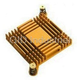
Heat Sink Passive BGA Push Pin 33.3°C/W Gold Anodized 10-5597-33
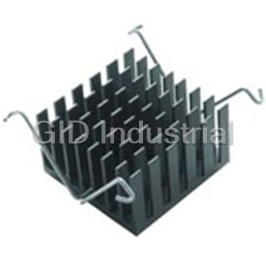
Heat Sink Passive BGA Push Pin 22.1C/W Black Anodized 10-5607-04
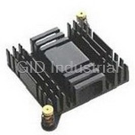
Heat Sink Passive BGA Push Pin Black Anodized 10-5607-05
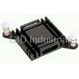
Heat Sink Passive BGA Push Pin Black Anodized 10-6326-27
Heat Sink Passive BGA Pin Array Push Pin 30.6C/W Black Anodized 10-6327-01
Heat Sink Passive BGA Solder Anchor 10.1°C/W Black Anodized 10-BRD1-03


Request a Quote

The quote request has been received

Close

Facing challenges or have inquiries? Feel free to contact us!
Call Us +1-469-283-2440
What they say about us
FANTASTIC RESOURCE
One of our top priorities is maintaining our business with precision, and we are constantly looking for affiliates that can help us achieve our goal. With the aid of GID Industrial, our obsolete product management has never been more efficient. They have been a great resource to our company, and have quickly become a go-to supplier on our list!
Bucher Emhart Glass
EXCELLENT SERVICE
With our strict fundamentals and high expectations, we were surprised when we came across GID Industrial and their competitive pricing. When we approached them with our issue, they were incredibly confident in being able to provide us with a seamless solution at the best price for us. GID Industrial quickly understood our needs and provided us with excellent service, as well as fully tested product to ensure what we received would be the right fit for our company.
Fuji
HARD TO FIND A BETTER PROVIDER
Our company provides services to aid in the manufacture of technological products, such as semiconductors and flat panel displays, and often searching for distributors of obsolete product we require can waste time and money. Finding GID Industrial proved to be a great asset to our company, with cost effective solutions and superior knowledge on all of their materials, it’d be hard to find a better provider of obsolete or hard to find products.
Applied Materials
CONSISTENTLY DELIVERS QUALITY SOLUTIONS
Over the years, the equipment used in our company becomes discontinued, but they’re still of great use to us and our customers. Once these products are no longer available through the manufacturer, finding a reliable, quick supplier is a necessity, and luckily for us, GID Industrial has provided the most trustworthy, quality solutions to our obsolete component needs.
Nidec Vamco
TERRIFIC RESOURCE
This company has been a terrific help to us (I work for Trican Well Service) in sourcing the Micron Ram Memory we needed for our Siemens computers. Great service! And great pricing! I know when the product is shipping and when it will arrive, all the way through the ordering process.
Trican Well Service
GO TO SOURCE
When I can't find an obsolete part, I first call GID and they'll come up with my parts every time. Great customer service and follow up as well. Scott emails me from time to time to touch base and see if we're having trouble finding something.....which is often with our 25 yr old equipment.
ConAgra Foods