

 Manufacturers
ANDERSON POWER PRODUCTS PMHPAF02S05

Description
Conn Power F 1 POS ST Cable Mount 1Terminal 1Port
PMHPAF02S05
Part Number
PMHPAF02S05
Price
Request Quote
Manufacturer
ANDERSON POWER PRODUCTS
Lead Time
Request Quote
Category
Connectors » Connector Power
Specifications
Manufacturer
Anderson Power Products
Manufacturers Part #
PMHPAF02S05
Lead Time
8 Week Lead Time
Sub-Category
Power Connectors
Factory Pack Quantity
1
Datasheet

Extracted Text
®
Additional APP Products
®
EBC / DIN Connectors
Powerpole Connectors
Multipole Connectors Power Pak Connectors
CHINA
EUROPE ASIA / PACIFIC TAIWAN
HEADQUARTERS
IDEAL Anderson Technologies (Shenzhen) Ltd.
Anderson Power Products® Ltd. IDEAL Anderson Asia Pacific Ltd. IDEAL Anderson Asia Pacific Ltd.
Anderson Power Products®
Block A8, Tantou Western Industrial Park
Unit 3 Europa Court Unit 922-928, Topsail Plaza Taiwan Branch, 4F.-2, No.116
13 Pratts Junction Road
Songgang, Baoan District
Europa Boulevard 11 On Sum Street Dadun 20th St., Situn District
Sterling, MA 01564-2305 USA
Shenzhen, PR. China 518105
Westbrook, Warrington Shatin N.T., Hong Kong Taichung City 407, Taiwan (R.O.C.)
T: 978-422-3600
T: +(86) 755 2768 2118/3393 2388
Cheshire, WA5 7TN United Kingdom T: +(852) 2636 0836 T: +(886) 4 2310 6451
F: 978-422-0128
F: +(86) 755 2768 2218
T: +44 (0) 1925 428390 F: +(852) 2635 9036 F: +(886) 4 2310 6460
F: +44 (0) 1925 520203
15826, CAT-CPC REV 05
VISIT US AT WWW.ANDERSONPOWER.COM
Anderson Power Products®
Anderson Power
®
Products
APP’s philosophy is to provide products and
services within the trading markets of our
customers. We currently serve our world-wide
customer base from customer support and
manufacturing facilities in Sterling, MA, U.S.A.,
Warrington UK for European customers, as
well as three Asia Pacific facilities: Shenzhen,
China, Shatin Hong Kong and Taichung City
407, Taiwan (R.O.C.).
Today, as a result of innovative design and
development, APP has evolved into a valued
supplier for a wide variety of markets including
Back-up Power, Telecom/Datacom and the
Material Handling Industries.
APP has established a reputation for high
quality products, on-time deliveries, and excellent customer service. As a result of modern manufacturing techniques and rigorous quality control
measures, APP assures that customers receive the quality products they deserve.
As a global company dedicated to best environmental practice, APP has taken steps to meet the RoHS directive for virtually all of their products. APP
believes that general compliance with the RoHS directive is not enough and that the RoHS status for individual APP products must be readily accessible
to customers twenty-four hours a day, seven days a week. The APP website search system allows customers to enter a part number and determine a
product’s compliance status to the RoHS directive.
APP looks forward to the challenges posed by the new technologies of the future and will continue its century long tradition of design excellence and
superior customer support to meet customers’ needs.
Anderson Power Products® may revise terms and conditions from time to time without notice. APP maintains this catalog as a ser vice to its customers. The entire content
(photographs and text) is ©copyrighted 2007 and may not be distributed, modified, reused, or otherwise used, except as provide d herein, without the express written
permission of APP. You may use the content only for your personal, non-commercial use.
APP will use reasonable efforts to include accurate and up-to-date content in the catalog. All product information contained in the catalog including illustrations,
specifications, and dimensions, are believed to be reliable as of the date of publishing, but is subject to change without noti ce. APP makes no warranty or representation
as to its accuracy. Content in the catalog may contain technical inaccuracies, typographical errors and may be changed or updat ed without notice. Current sales drawings
and specifications are available upon request.
Neither APP nor any party involved in creating, producing, or delivering this catalog shall be liable for any direct, incidenta l, consequential, indirect, or punitive damages
arising out of your use of this catalog or any errors or omissions in its content. All product names, whether or not appearing in large print or with the trademark symbol,
including, but not limited to A, A in circle, Anderson Power Products, PowerMod, Power Drawer, Power Clip and ACARA are tradema rks of APP, its affiliates, related
companies, licensers, and/or joint venture partners. The use or misuse of these trademarks, or any other content of this catalo g, except as permitted herein, is expressly
prohibited and may be in violation of intellectual property laws, which shall be aggressively enforced.
Index
®
Anderson Power Products , an ISO 9001:2000 certified company, is a world leader in the design and manufacture of quick-disconnect power connectors. Our connectors
are rated from 30 amps to 450 amps and up to 250 or 600 volts, AC/DC and comply with major worldwide specifications. With over one hundred years of power connection
and device experience, we provide off-the-shelf and custom solutions for OEMs.
Contents
® ®
PowerMod HP “A” Series...................................................... 2
PowerMod Series................................................................... 51
Single Pole Male.................................................... 4 One Row Female.................................................... 52
Single Pole Female................................................ 6 One Row Male........................................................ 56
Single Pole Right Angle Female............................. 8 Two Row Female.................................................... 60
Bus Bar Mount........................................................ 10
Two Row Male........................................................ 64
Dual Pole Male....................................................... 12 Three Row Female................................................. 68
Dual Pole Female................................................... 14 Three Row Male...................................................... 72
Dual Pole Right Angle Female................................ 16
Accessories............................................................. 76
Dual Pole Panel Mount Male.................................. 18
®
Dual Pole Panel Mount Blind Mate Female............. 20 Power Clip Series................................................................... 79
Power Clip............................................................... 80
®
PowerMod HP “B” Series...................................................... 22
Rocker Power Clip.................................................. 82
Single Pole Male..................................................... 24 Dual Pole Power Clip.............................................. 84
Single Pole Female................................................. 26
®
Single Pole Right Angle Female............................. 28
ACARA Series........................................................................ 87
Bus Bar Mount........................................................ 30
65 & 100 amp Two Pole Male Filter & Female
Dual Pole Male....................................................... 32 Power Connector.................................................... 88
Dual Pole Female................................................... 34 150 & 250 amp Two Pole Male Filter & Female
Dual Pole Right Angle Female................................ 36
Power Connector................................................... 92
Dual Pole Panel Mount Male.................................. 38
Dual Pole Panel Mount Blind Mate Female........... 40 Wire Conversion Chart........................................................... 96
Interpretation of Charts........................................................... 97
®
Power Drawer Series............................................................ 43
Glossary of Terminology.......................................................... 98
35 amp Series......................................................... 44 Part Number Index.................................................................. 99
75 amp Series......................................................... 46
Cross Reference..................................................... 48
Note:
(1) For patent / trademark information, please see www.andersonpower.com.
(2) Use APP recommended crimp tooling. Crimping by other means may disturb contact position in the housing and / or produce high resistance in the mated
connection, which can cause melting and other hazardous conditions. Please see www.andersonpower.com, tooling section, for the recommendations, changes /
additions and tips on connector crimping / soldering or preventative maintenance.
(3) All products in this catalog are RoHS compliant. For RoHS compliant information on individual part numbers, please see www.andersonpower.com for
the RoHS lookup index tool.
®
©Copyright 2007 Anderson Power Products
The data herein are solely for your information and not offered, or to be construed, as a warranty or contractual responsibility.
- 1 -
®
PowerMod HP
Connector Family - Series A
FEATURES
• Positive latching
Integral latches with ergonomic release provide over 50 lbs retention
• Available in straight, right angle, panel mount, blind
mate and bus bar styles
The flexibility of the PowerMod®HP system serves a broad range of
UL Current Rating
electronics applications
SP 220 Amps
DP 210 Amps
• Touch safe female connectors
CSA (30°C Rise) 130 Amps
Provide IP20 protection for safe, energized use outside the electronics
Mating Force
cabinet
SP 7 lbs. (31.14N)
DP 15 lbs. (66.72N)
• Polarized dual pole connectors with optional hex key
UL Voltage Rating 600 Volts
Dual pole housings prevent shorting from reverse mating and the optional
Wire Size (AWG) #6 to #2
hex key allows the user to create unique mating schemes
(mm²) 16 to 35
Insulation Withstanding Voltage 2200 Volts
• Strain relief option
Operating Temperature Range °C minus 40-130 °C
Reduces risk of wire insulation creep and reduces transmission of wire
Ambient Temperature Range °C minus 40-85 °C
loads to contacts improving service life
Latch Retention Force 50 lbs. (222N) min.
Contact Retention Force 100 lbs. (445N) min.
• Low connector mating forces
Mating
Connectors are easily mated and un-mated
a. No Load(Contact/Disconnect Cycles) 500 Cycles
b. Under Load(Hot Plug 250 cycles @ 120V) 80A
• Silver plated, high conductivity contacts
Housing & Cable Clamp PBT UL94 V-0
Offers greater longevity for high power, elevated temperature applications
Latch PEI UL94 V-0
Contacts Copper alloy
• Ease of assembly
Hardware Steel zinc chromate
Intuitive design allows for simplicity of assembly
PRODUCT INFORMATION
PowerMod®HP connectors, developed by Anderson Power Products, are the innovative New Generation of High Power Interconnections for the
Electronics Industry. The product family provides; cost effective reliability, superior safety and ergonomics, with broad design flexibility. The
positive latch and optional strain relief of PowerMod®HP connectors ensure superior reliability. The contacts are extremely durable and rated for
circuit interruption (true hot-pluggable). Our touch-safe female housing design with integral latch release presents a new standard for high power
connector safety and ergonomics. The housings are black UL94 V-0 material with latches in blue for clear identification.
The PowerMod®HP family offers excellent design flexibility with the availability of 10 different connector types.
• Single Pole Straight Male • Dual Pole Straight Male
• Single Pole Right Angle Female • Dual Pole Right Angle Female
• Single Pole Straight Female • Dual Pole Straight Female
• Single Pole Bus Bar Mount • Dual Pole Female Blind Mate Panel Mount
• Dual Pole Male Panel Mount
• Dual Pole Male Blind Mate Panel Mount
All PowerMod®HP connectors are available in American and metric wire sizes for further design freedom. APP offers pneumatic and hydraulic
bench tools as well as hand tools for the products which are also compatible with many third-party crimp tooling.
Applications: Back-Up Power, Power Supplies, Cellular Infrastructure, Telecommunications, Industrial Power.
- 2 -
Connector Family - Series A
Single Pole Right Angle Female Single Pole Male & Female Bus Bar Mount
Dual Pole Right Angle Female Dual Pole Male & Female
Dual Pole Panel Mount Male Dual Pole Blindmate Female Dual Pole Blindmate Male
All Data Subject To Change Without Notice
- 3 -
®
PowerMod HP
Single Pole Male - Series A
PowerMod HP connectors, developed by
Features
Anderson Power Products, are the innovative
New Generation of High Power
• Positive latching
Interconnections for the Electronics Industry.
Integral latches with ergonomic release
provide over 50 lbs retention
The touch-safe, positive latching, PowerMod
HP female connector design presents a new
standard for high power connector safety. The
• Strain relief option
ergonomic latch release is simple to operate
Reduces risk of wire insulation creep and
and is colored blue for clear identification.
reduces transmission of wire loads to contacts
Housings are a black UL94 V-0 flame retardant
improving service life
material.
• Low connector mating forces
PowerMod HP contacts are durable and rated
Connectors are easily mated and un-mated
for circuit interruption (true hot-pluggable).
Series A contacts are available in #6 to #2
2 2
• Silver plated, high conductivity
American wire gauge and 16mm to 35mm
metric wire sizes for global design freedom. contacts
Our optional strain relief ensures superior
Offers greater longevity for high power,
contact reliability under adverse operating
elevated temperature applications
conditions.
• Ease of assembly
APP PowerMod HP connectors embody the
Intuitive design allows for simplicity of assembly
highest quality in the industry and meet all
applicable industry standards.
SPECIFICATIONS
Electrical Mechanical
Current Rating Mating Force 7 lbs. (31.14N) avg
UL 220 Amps Latch Retention Force 50 lbs. (222N) min
CSA (30°C Rise) 130 Amps Contact Retention Force 100 lbs. (445N) min
UL / CSA Voltage Rating 600 Volts Mating
Wire Size (AWG) #6 to #2 a. No Load(Contact/Disconnect Cycles) 500 Cycles
(mm²) 16 to 35 b. Under Load(Hot Plug 250 cycles @ 120V) 80A
Insulation Withstanding Voltage 2200 Volts Materials
Operating Temperature Range °C minus 40-130 °C Housing & Cable Clamp PBT UL94 V-0
Ambient Temperature Range °C minus 40-85 °C Latch PEI UL94 V-0
Contacts Copper alloy silver plate
Hardware Steel zinc chromate
ORDERING INFORMATION
PowerMod HP Part Number Plan - Single Pole Male Components
Series Series Gender Model Wire Size
Part
Number Description
PMHP A M 01 P05
PMHPAM01 Housing Kit, Male, Single Pole, Straight
A *
PMHPAM02 Housing Kit with Cable Clamp, Male, Single Pole, Straight
M - Male
PMHPAP05 Pin, Series A, Crimp for 6 AWG wire
01 - Single Pole Straight
PMHPAP04 Pin, Series A, Crimp for 16mm² wire
02 - Single Pole Straight with Cable Clamp
PMHPAP03 Pin, Series A, Crimp for 4 AWG wire
P05 - 6 AWG
PMHPAP02 Pin, Series A, Crimp for 25mm² wire
P04 - 16mm²
PMHPAP01 Pin, Series A, Crimp for 2 AWG & 35mm² wire
P03 - 4 AWG
PMHPAC01 Single Pole Cable Clamp Kit
P02 - 25mm²
P01 - 2 AWG & 35mm²
* Maximum wire size 2 AWG or 35mm²
- 4 -
Single Pole
Male - Series A
ORDERING INFORMATION TEMPERATURE CHART
PowerMod®HP Single Pole Series “A”
Tooling
Temperature Rise
Pneumatic Production Tool 50
45
Part Number of
40
Number Locator P/N Crimps
Wire Size Die P/N
35
#2 AWG
30
35mm²
1387G2 1303G13 1304G19 2
25
25mm² 1387G2 1303G13 1304G19 2 20
15
#4 AWG 1387G2 1303G14 1304G19 2
10
16mm² 1387G2 1303G14 1304G19 2
5
#6 AWG 1387G2 1303G14 1304G19 2
0
0 20 40 60 80 100 120 140 160 180
Current (A)
2 AWG 4 AWG 6 AWG
Number of
Hydraulic Battery Crimps
Wire Size Die P/N
* Double crimp is required to achieve stated electrical specifications
#2 AWG
35mm²
1387G3 1370 1322G7 2
25mm² 1387G3 1370 1322G11 2
PowerMod®HP Single Pole De-rating Curve Series “A”
#4 AWG 1387G3 1370 1322G8 2
Per IEC 60512-5
110
16mm² 1387G3 1370 1322G10 2
100
#6 AWG 1387G3 1370 1322G9 2
90
80
70
DIMENSIONS
60
50
Front Without Front With
40
Strain Relief Strain Relief
30
20
10
0
0 20 40 60 80 100 120 140 160 180 200 220 240 260
[ 31 ]
[ 37.1 ]
1.22
1.46
Current (A)
2 AWG 4 AWG 6 AWG
[ 34.8 ]
* Double crimp is required to achieve stated electrical specifications
[ 33.2 ]
1.37
1.31
MATING CONNECTORS
Single Pole Right Single Pole Female
Angle Female
Side
[ 80.2 ]
3.16
[ 65.1 ]
2.56
All Data Subject To Change Without Notice
- 5 -
Ambient Temperature (°C) Temperature (°C)
®
PowerMod HP
Single Pole Female - Series A
PowerMod HP connectors, developed by
Features
Anderson Power Products, are the innovative
New Generation of High Power
• Positive Latching
Interconnections for the Electronics Industry.
Integral latches with ergonomic release provide
over 50 lbs retention
The touch-safe, positive latching, PowerMod
HP female connector design presents a new
• Touch safe female connectors
standard for high power connector safety. The
Provides IP20 protection for safe, energized use
ergonomic latch release is simple to operate
outside the electronics cabinet
and is colored blue for clear identification.
Housings are a black UL94 V-0 flame retardant
• High performance, hot pluggable
material.
female contacts
Our patented design provides greater longevity for
PowerMod HP contacts are durable and rated
high power, elevated temperature applications
for circuit interruption (true hot-pluggable).
Series A contacts are available in #6 to #2
2 2
American wire gauge and 16mm to 35mm • Strain relief option
metric wire sizes for global design freedom.
Reduces risk of wire insulation creep and reduces
Our optional strain relief ensures superior
transmission of wire loads to contacts improving
contact reliability under adverse operating
service life
conditions.
• Low connector mating forces
APP PowerMod HP connectors embody the
Connectors are easily mated and un-mated
highest quality in the industry and meet all
applicable industry standards.
SPECIFICATIONS
Electrical Mechanical
Current Rating Mating Force 7 lbs. (31.14N) avg
UL 220 Amps Latch Retention Force 50 lbs. (222N) min
CSA (30°C Rise) 130 Amps Contact Retention Force 100 lbs. (445N) min
UL / CSA Voltage Rating 600 Volts Mating
Wire Size (AWG) #6 to #2 a. No Load(Contact/Disconnect Cycles) 500 Cycles
(mm²) 16 to 35 b. Under Load(Hot Plug 250 cycles @ 120V) 80A
Insulation Withstanding Voltage 2200 Volts Materials
Operating Temperature Range °C minus 40-130 °C Housing & Cable Clamp PBT UL94 V-0
Ambient Temperature Range °C minus 40-85 °C Latch PEI UL94 V-0
Contacts Copper alloy silver plate
Hardware Steel zinc chromate
ORDERING INFORMATION
PowerMod HP Part Number Plan - Single Pole Female Components
Series Series Gender Model Wire Size
Part
PMHP A F 01 S05 Number Description
PMHPAF01 Housing Kit, Female, Single Pole, Straight
A *
PMHPAF02 Housing Kit with Cable Clamp,Female, Single Pole, Straight
F - Female
PMHPAS05 Socket, Series A, Crimp for 6 AWG wire
01 - Single Pole Straight
PMHPAS04 Socket, Series A, Crimp for 16mm² wire
02 - Single Pole Straight with Cable Clamp
PMHPAS03 Socket, Series A, Crimp for 4 AWG wire
S05 - 6 AWG
PMHPAS02 Socket, Series A, Crimp for 25mm² wire
S04 - 16mm²
PMHPAS01 Socket, Series A, Crimp for 2 AWG & 35mm² wire
S03 - 4 AWG
PMHPAC01 Single Pole Cable Clamp Kit
S02 - 25mm²
S01 - 2 AWG & 35mm²
* Maximum wire size 2 AWG or 35mm²
- 6 -
Single Pole
Female - Series A
ORDERING INFORMATION TEMPERATURE CHART
PowerMod®HP Single Pole Series “A”
Tooling
Temperature Rise
50
Pneumatic Production Tool
45
Part Number of
40
Number Locator P/N Crimps
Wire Size Die P/N
35
#2 AWG
30
35mm²
1387G2 1303G13 1304G19 2
25
25mm² 1387G2 1303G13 1304G19 2 20
15
#4 AWG 1387G2 1303G14 1304G19 2
10
16mm² 1387G2 1303G14 1304G19 2
5
#6 AWG 1387G2 1303G14 1304G19 2
0
0 20 40 60 80 100 120 140 160 180
Hand Tool
Current (A)
4 AWG
2 AWG 6 AWG
Number of
Hydraulic Battery Crimps
Wire Size Die P/N
* Double crimp is required to achieve stated electrical specifications
#2 AWG
35mm²
1387G3 1370 1322G7 2
25mm² 1387G3 1370 1322G11 2
PowerMod®HP Single Pole De-rating Curve Series “A”
#4 AWG 1387G3 1370 1322G8 2
Per IEC 60512-5
110
16mm² 1387G3 1370 1322G10 2
100
#6 AWG 1387G3 1370 1322G9 2
90
80
70
DIMENSIONS
60
50
Front Without Front With
40
30
Strain Relief Strain Relief
20
[ 33.2 ] 10
0
1.31
0 20 40 60 80 100 120 140 160 180 200 220 240 260
[ 37.1 ]
1.46 Current (A)
[ 30.6 ]
4 AWG
2 AWG 6 AWG
1.21
* Double crimp is required to achieve stated electrical specifications
[ 34.7 ]
1.36
MATING CONNECTORS
Side
Single Pole Bus Bar Male Single Pole Male
[ 82.1 ]
3.23
[ 65.2 ]
2.57
All Data Subject To Change Without Notice
- 7 -
Temperature (°C)
Ambient Temperature (°C)
®
PowerMod HP
Single Pole Right Angle Female - Series A
PowerMod HP connectors, developed by
Features
Anderson Power Products, are the innovative
New Generation of High Power
• Right angle connector
Interconnections for the Electronics Industry.
Offers short mated length for tight wiring
The touch-safe, positive latching, PowerMod
applications
HP female connector design presents a new
standard for high power connector safety. The
• Positive latching
ergonomic latch release is simple to operate
Integral Latches with ergonomic release provide
and is colored blue for clear identification.
over 50 lbs retention
Housings are a black UL94 V-0 flame retardant
material.
• Touch safe female connectors
PowerMod HP contacts are durable and rated
Provides IP20 protection for safe, energized use
for circuit interruption (true hot-pluggable).
outside the electronics cabinet
Series A contacts are available in #6 to #2
2 2
American wire gauge and 16mm to 35mm
metric wire sizes for global design freedom.
• High performance, hot pluggable
Our *strain relief ensures superior contact
female contacts
reliability under adverse operating conditions.
Our patented design provides greater longevity for
high power, elevated temperature applications
APP PowerMod HP connectors embody the
highest quality in the industry and meet all
applicable industry standards.
• Low connector mating forces
Connectors are easily mated and un-mated
* Strain relief not optional on right angle
SPECIFICATIONS
Electrical Mechanical
Current Rating Mating Force 7 lbs. (31.14N) avg
UL 220 Amps Latch Retention Force 50 lbs. (222N) min
CSA (30°C Rise) 130 Amps Contact Retention Force 100 lbs. (445N) min
UL / CSA Voltage Rating 600 Volts Mating
Wire Size (AWG) #6 to #2 a. No Load(Contact/Disconnect Cycles) 500 Cycles
(mm²) 16 to 35 b. Under Load(Hot Plug 250 cycles @ 120V) 80A
Insulation Withstanding Voltage 2200 Volts Materials
Operating Temperature Range °C minus 40-130 °C Housing & Cable Clamp PBT UL94 V-0
Ambient Temperature Range °C minus 40-85 °C Latch PEI UL94 V-0
Contacts Copper alloy silver plate
Hardware Steel zinc chromate
ORDERING INFORMATION
PowerMod HP Part Number Plan - Single Pole Right Components
Angle Female
Part
Series Series Gender Model Wire Size
Number Description
PMHPAF03 Housing Kit with Cable Clamp,Female, Single Pole, R/A
PMHP A F 3 S10
PMHPAS10 Socket, Series A, Crimp for 6 AWG wire
A *
PMHPAS09 Socket, Series A, Crimp for 16mm² wire
F - Female
PMHPAS08 Socket, Series A, Crimp for 4 AWG wire
03 - Single Pole R/A with cable clamp
PMHPAS07 Socket, Series A, Crimp for 25mm² wire
S10 - 6 AWG
PMHPAS06 Socket, Series A, Crimp for 2 AWG & 35mm² wire
S09 - 16mm²
S08 - 4 AWG
S07 - 25mm²
S06 - 2 AWG & 35mm²
* Maximum wire size 2 AWG or 35mm²
- 8 -
Single Pole
Right Angle Female - Series A
ORDERING INFORMATION TEMPERATURE CHART
PowerMod®HP Single Pole Series “A”
Tooling
Temperature Rise
50
Pneumatic Production Tool
45
Part Number of
40
Number Locator P/N Crimps
Wire Size Die P/N
35
#2 AWG
30
35mm²
1387G2 1303G13 1304G19 2
25
20
25mm² 1387G2 1303G13 1304G19 2
15
#4 AWG 1387G2 1303G14 1304G19 2
10
16mm² 1387G2 1303G14 1304G19 2
5
#6 AWG 1387G2 1303G14 1304G19 2
0
0 20 40 60 80 100 120 140 160 180
Hand Tool
Current (A)
4 AWG
2 AWG 6 AWG
Number of
Hydraulic Battery Crimps
Wire Size Die P/N
* Double crimp is required to achieve stated electrical specifications
#2 AWG
35mm²
1387G3 1370 1322G7 2
25mm² 1387G3 1370 1322G11 2
PowerMod®HP Single Pole De-rating Curve Series “A”
#4 AWG 1387G3 1370 1322G8 2
Per IEC 60512-5
110
16mm² 1387G3 1370 1322G10 2
100
#6 AWG 1387G3 1370 1322G9 2
90
80
70
DIMENSIONS
60
50
Side
40
30
20
10
0
[ 26.4 ]
0 20 40 60 80 100 120 140 160 180 200 220 240 260
[ 70.1 ]
1.04
2.76
Current (A)
2 AWG 4 AWG 6 AWG
* Double crimp is required to achieve stated electrical specifications
Top Front
MATING CONNECTORS
Single Pole Male Single Pole Bus Bar Male
[ 68.3 ]
2.69
[ 37.1 ]
1.46
All Data Subject To Change Without Notice
- 9 -
Temperature (°C)
Ambient Temperature (°C)
®
PowerMod HP
Single Pole Bus Bar - Series A
PowerMod HP connectors, developed by
Features
Anderson Power Products, are the innovative
New Generation of High Power
• Low connector mating forces
Interconnections for the Electronics Industry.
Connectors are easily mated and un-mated
APP PowerMod HP connectors embody the
• Silver plated, high conductivity
highest quality in the industry and meet all
contacts
applicable industry standards.
Offers greater longevity for high power,
elevated temperature applications
• Ease of assembly
Intuitive design allows for simplicity of assembly
SPECIFICATIONS
Current Rating Mating Force 7 lbs. (31.14N) avg
UL 220 Amps Latch Retention Force 50 lbs. (222N) min
130 Amps Contact Retention Force 100 lbs. (445N) min
UL / CSA Voltage Rating 600 Volts Mating
Bus Bar .12 [3.0] min a. No Load(Contact/Disconnect Cycles) 500 Cycles
.25 [6.4] max b. Under Load(Hot Plug 250 cycles @ 120V) 80A
Insulation Withstanding Voltage 2200 Volts
Operating Temperature Range °C minus 40-130 °C Housing PBT UL94 V-0
Ambient Temperature Range °C minus 40-85 °C Contacts Copper alloy silver plate
Hardware Steel zinc chromate
ORDERING INFORMATION
PowerMod HP Part Number Plan - Single Pole Bus Bar
Components
Series Series Gender Model Wire Size
Part
PMHP A M 04 P06 Number Description
PMHPAP06 Pin Series A, Bus Bar
A *
M - Male
04 - Bus Bar Mount
P06 - Pin Bus Bar
- 10 -
Single Pole
Bus Bar - Series A
ORDERING INFORMATION TEMPERATURE CHART
PowerMod®HP Single Pole Series “A”
Tooling For Mating Connectors
Temperature Rise
Pneumatic Production Tool
50
45
Part Number of
40
Number Locator P/N Crimps
Wire Size Die P/N
35
#2 AWG
30
35mm²
1387G2 1303G13 1304G19 2
25
25mm² 1387G2 1303G13 1304G19 2 20
15
#4 AWG 1387G2 1303G14 1304G19 2
10
16mm² 1387G2 1303G14 1304G19 2
5
#6 AWG 1387G2 1303G14 1304G19 2
0
0 20 40 60 80 100 120 140 160 180
Hand Tool
Current (A)
4 AWG
Number of 2 AWG 6 AWG
Hydraulic Battery Crimps
Wire Size Die P/N
* Double crimp is required to achieve stated electrical specifications
#2 AWG
35mm²
1387G3 1370 1322G7 2
25mm² 1387G3 1370 1322G11 2
PowerMod®HP Single Pole De-rating Curve Series “A”
#4 AWG 1387G3 1370 1322G8 2
Per IEC 60512-5
110
16mm² 1387G3 1370 1322G10 2
100
#6 AWG 1387G3 1370 1322G9 2
90
80
70
DIMENSIONS
60
Front 50
40
[ 23.4 ]
30
.92
20
10
[ 23.4 ]
0
.92
0 20 40 60 80 100 120 140 160 180 200 220 240 260
Current (A)
Side 4 AWG
2 AWG 6 AWG
[ 30.5 ]
BUSBAR
* Double crimp is required to achieve stated electrical specifications
1.20
[ 13.1 ]
MATING CONNECTORS
.52
Single Pole Right Single Pole Female
Angle Female
45°
Back
[ 10.16 ]
.400
[ 4.83 ]
[ 7.49 ]
Ø .190
.295
Ø
HOUSING OUTLINE
All Data Subject To Change Without Notice
- 11 -
Ambient Temperature (°C) Temperature (°C)
®
PowerMod HP
Dual Pole Male - Series A
PowerMod HP connectors, developed by
Features
Anderson Power Products, are the innovative
New Generation of High Power
• Positive latching
Interconnections for the Electronics Industry.
Integral latches with ergonomic release
provide over 50 lbs retention
The touch-safe, positive latching, PowerMod
HP female connector design presents a new
• Strain relief option
standard for high power connector safety. The
Reduces risk of wire insulation creep and
ergonomic latch release is simple to operate
reduces transmission of wire loads to contacts
and is colored blue for clear identification.
Housings are a black UL94 V-0 flame retardant improving service life
material.
• Low connector mating forces
PowerMod HP contacts are durable and rated
Connectors are easily mated and un-mated
for circuit interruption (true hot-pluggable).
Series A contacts are available in #6 to #2
• Silver plated, high conductivity
2 2
American wire gauge and 16mm to 35mm
contacts
metric wire sizes for global design freedom.
Offers greater longevity for high power,
Our optional strain relief ensures superior
elevated temperature applications
contact reliability under adverse operating
conditions.
• Ease of assembly
APP PowerMod HP connectors embody the
Intuitive design allows for simplicity of assembly
highest quality in the industry and meet all
applicable industry standards.
SPECIFICATIONS
Electrical Mechanical
Current Rating Mating Force 15 lbs. (66.72N) avg
UL 210 Amps Latch Retention Force 50 lbs. (222N) min
CSA (30°C Rise) 130 Amps Contact Retention Force 100 lbs. (445N) min
UL / CSA Voltage Rating 600 Volts Mating
Wire Size (AWG) #6 to #2 a. No Load(Contact/Disconnect Cycles) 500 Cycles
(mm²) 16 to 35 b Under Load(Hot Plug 250 cycles @ 120V) 80A
Insulation Withstanding Voltage 2200 Volts Materials
Operating Temperature Range °C minus 40-130 °C Housing & Cable Clamp PBT UL94 V-0
Ambient Temperature Range °C minus 40-85 °C Latch PEI UL94 V-0
Contacts Copper alloy silver plate
Hardware Steel zinc chromate
ORDERING INFORMATION
PowerMod HP Part Number Plan - Dual Pole Male Components
Series Series Gender Model Wire Size
Part
Number Description
PMHP A M 11 P05
PMHPAM11 Housing Kit, Male, Dual Pole, Straight
A *
PMHPAM12 Housing Kit with Cable Clamp, Male, Dual Pole, Straight
M - Male
PMHPAP05 Pin, Series A, Crimp for 6 AWG wire
11 - Dual Pole Straight
PMHPAP04 Pin, Series A, Crimp for 16mm² wire
12 - Dual Pole Straight with Cable Clamp
PMHPAP03 Pin, Series A, Crimp for 4 AWG wire
P05 - 6 AWG
PMHPAP02 Pin, Series A, Crimp for 25mm² wire
P04 - 16mm²
PMHPAP01 Pin, Series A, Crimp for 2 AWG & 35mm² wire
P03 - 4 AWG
P02 - 25mm² PMHPAC02 Dual Pole Cable Clamp Kit
P01 - 2 AWG & 35mm²
* Maximum wire size 2 AWG or 35mm²
- 12 -
Dual Pole
Male - Series A
ORDERING INFORMATION TEMPERATURE CHART
PowerMod®HP Dual Pole Series “A”
Tooling
Temperature Rise
50
Pneumatic Production Tool
45
Part Number of
40
Number Locator P/N Crimps
Wire Size Die P/N
35
#2 AWG
30
35mm²
1387G2 1303G13 1304G19 2
25
25mm² 1387G2 1303G13 1304G19 2
20
15
#4 AWG 1387G2 1303G14 1304G19 2
10
16mm² 1387G2 1303G14 1304G19 2
5
#6 AWG 1387G2 1303G14 1304G19 2
0
0 20 40 60 80 100 120 140 160
Hand Tool
Current (A)
4 AWG
2 AWG 6 AWG
Number of
Hydraulic Battery Crimps
Wire Size Die P/N * Double crimp is required to achieve stated electrical specifications
#2 AWG
35mm²
1387G3 1370 1322G7 2
PowerMod®HP Dual Pole De-rating Curve Series “A”
25mm² 1387G3 1370 1322G11 2
Per IEC 60512-5
#4 AWG 1387G3 1370 1322G8 2
110
100
16mm² 1387G3 1370 1322G10 2
90
#6 AWG 1387G3 1370 1322G9 2
80
70
60
DIMENSIONS
50
40
Front Without
30
Strain Relief
20
10
0
[ 29.2 ]
0 20 40 60 80 100 120 140 160 180 200 220 240 260
[ 29.9 ]
1.15
[ 63.7 ]
1.18
2.51 Current (A)
4 AWG
2 AWG 6 AWG
Side
* Double crimp is required to achieve stated electrical specifications
MATING CONNECTORS
Dual Pole Straight Dual Pole Right Angle
Female Female
[ 65.7 ]
2.59
[ 82.6 ]
3.25
Front With
Strain Relief
[ 67.2 ]
2.65
All Data Subject To Change Without Notice
- 13 -
Temperature (°C)
Ambient Temperature (°C)
®
PowerMod HP
Dual Pole Female - Series A
PowerMod HP connectors, developed by
Features
Anderson Power Products, are the innovative
New Generation of High Power
• Positive latching
Interconnections for the Electronics Industry.
Integral latches with ergonomic release
provide over 50 lbs retention
The touch-safe, positive latching, PowerMod
HP female connector design presents a new
• Touch safe female connectors
standard for high power connector safety. The
Provides IP20 protection for safe, energized
ergonomic latch release is simple to operate
use outside the electronics cabinet
and is colored blue for clear identification.
Housings are a black UL94 V-0 flame retardant
• High performance, hot pluggable
material.
female contacts
Our patented design provides greater longevity
PowerMod HP contacts are durable and rated
for high power, elevated temperature applications
for circuit interruption (true hot-pluggable).
Series A contacts are available in #6 to #2
2 2
• Strain relief option
American wire gauge and 16mm to 35mm
metric wire sizes for global design freedom. Reduces risk of wire insulation creep and
Our optional strain relief ensures superior reduces transmission of wire loads to contacts
contact reliability under adverse operating
improving service life
conditions.
• Low connector mating forces
APP PowerMod HP connectors embody the
Connectors are easily mated and un-mated
highest quality in the industry and meet all
applicable industry standards.
SPECIFICATIONS
Electrical Mechanical
Current Rating Mating Force 15 lbs. (66.72N) avg
UL 210 Amps Latch Retention Force 50 lbs. (222N) min
CSA (30°C Rise) 130 Amps Contact Retention Force 100 lbs. (445N) min
UL / CSA Voltage Rating 600 Volts Mating
Wire Size (AWG) #6 to #2 a. No Load(Contact/Disconnect Cycles) 500 Cycles
(mm²) 16 to 35 b Under Load(Hot Plug 250 cycles @ 120V) 80A
Insulation Withstanding Voltage 2200 Volts Materials
Operating Temperature Range °C minus 40-130 °C Housing & Cable Clamp PBT UL94 V-0
Ambient Temperature Range °C minus 40-85 °C Latch PEI UL94 V-0
Contacts Copper alloy silver plate
Hardware Steel zinc chromate
ORDERING INFORMATION
PowerMod HP Part Number Plan - Dual Pole Female
Components
Series Series Gender Model Wire Size
Part
PMHP A F 11 S05 Number Description
PMHPAF11 Housing Kit, Female, Dual Pole, Straight
A *
PMHPAF12 Housing Kit with Cable Clamp, Female, Dual Pole, Straight
F - Female
PMHPAS05 Socket, Series A, Crimp for 6 AWG wire
11 - Dual Pole Straight
12 - Dual Pole Straight with Cable Clamp PMHPAS04 Socket, Series A, Crimp for 16mm² wire
S05 - 6 AWG PMHPAS03 Socket, Series A, Crimp for 4 AWG wire
PMHPAS02 Socket, Series A, Crimp for 25mm² wire
S04 - 16mm²
S03 - 4 AWG PMHPAS01 Socket, Series A, Crimp for 2 AWG & 35mm² wire
S02 - 25mm² PMHPAC02 Dual Pole Cable Clamp Kit
S01 - 2 AWG & 35mm
* Maximum wire size 2 AWG or 35mm²
- 14 -
Dual Pole
Female - Series A
ORDERING INFORMATION TEMPERATURE CHART
Tooling PowerMod®HP Dual Pole Series “A”
Temperature Rise
Pneumatic Production Tool 50
45
Part Number of
40
Number Locator P/N Crimps
Wire Size Die P/N
35
#2 AWG
30
35mm²
1387G2 1303G13 1304G19 2
25
25mm² 1387G2 1303G13 1304G19 2
20
#4 AWG 1387G2 1303G14 1304G19 2 15
10
16mm² 1387G2 1303G14 1304G19 2
5
#6 AWG 1387G2 1303G14 1304G19 2
0
0 20 40 60 80 100 120 140 160
Hand Tool
Current (A)
4 AWG
Number of 2 AWG 6 AWG
Hydraulic Battery Crimps
Wire Size Die P/N
* Double crimp is required to achieve stated electrical specifications
#2 AWG
35mm²
1387G3 1370 1322G7 2
PowerMod®HP Dual Pole De-rating Curve Series “A”
25mm² 1387G3 1370 1322G11 2
Per IEC 60512-5
#4 AWG 1387G3 1370 1322G8 2
110
16mm² 1387G3 1370 1322G10 2
100
90
#6 AWG 1387G3 1370 1322G9 2
80
70
Accessories
60
50
Part
40
Number Description
30
PMHPAFDC Dust Cover
20
10
DIMENSIONS
0
0 20 40 60 80 100 120 140 160 180 200 220 240 260
Front Without Front With
Current (A)
Strain Relief Strain Relief
4 AWG
2 AWG 6 AWG
* Double crimp is required to achieve stated electrical specifications
[ 29.8 ]
1.17
MATING CONNECTORS
[ 63.7 ] [ 67.3 ]
Dual Pole Dual Pole Panel
2.51 2.65
Straight Male Mount Male
Side
[ 66.8 ]
[ 82.2 ]
2.63
3.23
All Data Subject To Change Without Notice
- 15 -
Temperature (°C)
Ambient Temperature (°C)
®
PowerMod HP
Dual Pole Right Angle Female - Series A
PowerMod HP connectors, developed by
Features
Anderson Power Products, are the innovative
New Generation of High Power
• Right angle connector
Interconnections for the Electronics Industry.
Offers short mated length for tight
The touch-safe, positive latching, PowerMod
wiring applications
HP female connector design presents a new
standard for high power connector safety.
• Positive latching
The ergonomic latch release is simple to
Integral Latches with ergonomic release provide
operate and is colored blue for clear
over 50 lbs retention
identification. Housings are a black UL94 V-0
flame retardant material.
• Touch safe female connectors
PowerMod HP contacts are durable and
Provides IP20 protection for safe, energized use
rated for circuit interruption (true hot-
outside the electronics cabinet
pluggable). Series A contacts are available in
2
#6 to #2 American wire gauge and 16mm to
2
35mm metric wire sizes for global design
• High performance, hot pluggable
freedom. Our *strain relief ensures superior
female contacts
contact reliability under adverse operating
Our patented design provides greater longevity
conditions.
for high power, elevated temperature applications
APP PowerMod HP connectors embody the
highest quality in the industry and meet all
• Low connector mating forces
applicable industry standards.
Connectors are easily mated and un-mated
* Strain relief not optional on right angle
SPECIFICATIONS
Electrical Mechanical
Current Rating Mating Force 15 lbs. (66.72N) avg
UL 210 Amps Latch Retention Force 50 lbs. (222N) min
CSA (30°C Rise) 130 Amps Contact Retention Force 100 lbs. (445N) min
UL / CSA Voltage Rating 600 Volts
Wire Size (AWG) #6 to #2 a. No Load(Contact/Disconnect Cycles) 500 Cycles
(mm²) 16 to 35 b. Under Load(Hot Plug 250 cycles @ 120V) 80A
Insulation Withstanding Voltage 2200 Volts Materials
Operating Temperature Range °C minus 40-130 °C Housing & Cable Clamp PBT UL94 V-0
Ambient Temperature Range °C minus 40-85 °C Latch PEI UL94 V-0
Contacts Copper alloy silver plate
Hardware Steel zinc chromate
ORDERING INFORMATION
PowerMod HP Part Number Plan - Dual Pole Components
Right Angle Female
Part
Series Series Gender Model Wire Size
Number Description
PMHPAF13 Housing Kit With Cable Clamp, Female, Dual Pole, R/A
PMHP A F 13 S10
PMHPAS10 Socket, Series A, Crimp for 6 AWG wire
A *
PMHPAS09 Socket, Series A, Crimp for 16mm² wire
F - Female
PMHPAS08 Socket, Series A, Crimp for 4 AWG wire
13 - Dual Pole R/A with Cable Clamp
PMHPAS07 Socket, Series A, Crimp for 25mm² wire
S10 - 6 AWG
PMHPAS06 Socket, Series A, Crimp for 2 AWG & 35mm² wire
S09 - 16mm²
S08 - 4 AWG
S07 - 25mm²
S06 - 2 AWG & 35mm²
* Maximum wire size 2 AWG or 35mm²
- 16 -
Dual Pole
Right Angle Female - Series A
ORDERING INFORMATION TEMPERATURE CHART
Tooling PowerMod®HP Dual Pole Series “A”
Temperature Rise
Pneumatic Production Tool
50
45
Part Number of
40
Number Locator P/N Crimps
Wire Size Die P/N
35
#2 AWG
30
35mm²
1387G2 1303G13 1304G19 2
25
25mm² 1387G2 1303G13 1304G19 2
20
#4 AWG 1387G2 1303G14 1304G19 2
15
16mm² 1387G2 1303G14 1304G19 2 10
5
#6 AWG 1387G2 1303G14 1304G19 2
0
0 20 40 60 80 100 120 140 160
Hand Tool
Current (A)
Number of 4 AWG
2 AWG 6 AWG
Hydraulic Battery Crimps
Wire Size Die P/N
* Double crimp is required to achieve stated electrical specifications
#2 AWG
35mm²
1387G3 1370 1322G7 2
PowerMod®HP Dual Pole De-rating Curve Series “A”
25mm² 1387G3 1370 1322G11 2
Per IEC 60512-5
#4 AWG 1387G3 1370 1322G8 2
110
16mm² 1387G3 1370 1322G10 2
100
90
#6 AWG 1387G3 1370 1322G9 2
80
70
Accessories
60
50
Part
40
Number Description
30
PMHPAFDC Dust Cover
20
10
DIMENSIONS
0
0 20 40 60 80 100 120 140 160 180 200 220 240 260
Front With Side With
Current (A)
Strain Relief Strain Relief
4 AWG
2 AWG 6 AWG
[ 29.2 ] [ 25.5 ]
* Double crimp is required to achieve stated electrical specifications
1.15
1.01
MATING CONNECTORS
[ 67 ]
2.64
Dual Pole Dual Pole Panel
Straight Male Mount Male
[ 63.8 ]
2.51
Top
[ 67.2 ]
26.5
All Data Subject To Change Without Notice
- 17 -
Temperature (°C)
Ambient Temperature (°C)
®
PowerMod HP
Dual Pole Panel Mount Male - Series A
PowerMod HP connectors, developed by
Features
Anderson Power Products, are the
innovative New Generation of High Power
• Positive latching
Interconnections for the Electronics Industry.
Integral Latches with ergonomic release
The touch-safe PowerMod HP female panel provide over 50 lbs retention
connector is designed for high power
connector safety. Male panel connectors
• Low connector mating forces
are designed for blind mating with female
Connectors are easily mated and un-mated
panel connectors or positive latching with
female cable connectors. Housings are a
black UL94 V-0 flame retardant material. • Blind mate panel mount option
Provides over +/- .125" (3mm) of float mount
Panel Mount
PowerMod HP contacts are durable and
capability
rated for circuit interruption (true hot-
pluggable). Series A contacts are available
• Ease of assembly
in #6 to #2 American wire gauge and
2 2
16mm to 35mm metric wire sizes for global Intuitive design allows for simplicity of
design freedom.
assembly
Our optional blind mating hardware
accommodates up to +/- .125" (3mm) of
misalignment and is available for both male
and female panel connectors.
APP PowerMod HP connectors embody the
highest quality in the industry and meet all
Panel Mount Blind Mate
applicable industry standards.
SPECIFICATIONS
Electrical Mechanical
Current Rating Mating Force 15 lbs. (66.72N) avg
UL 210 Amps Latch Retention Force 50 lbs. (222N) min
CSA (30°C Rise) 130 Amps Contact Retention Force 100 lbs. (445N) min
UL / CSA Voltage Rating 600 Volts Mating
Wire Size (AWG) #6 to #2 a. No Load(Contact/Disconnect Cycles) 500 Cycles
(mm²) 16 to 35 b. Under Load(Hot Plug 250 cycles @ 120V) 80A
Insulation Withstanding Voltage 2200 Volts Materials
Operating Temperature Range °C minus 40-130 °C Housing & Cable Clamp PBT UL94 V-0
Ambient Temperature Range °C minus 40-85 °C Latch PEI UL94 V-0
Contacts Copper alloy silver plate
Hardware Steel zinc chromate
ORDERING INFORMATION
Components
PowerMod HP Part Number Plan - Dual Pole
Panel Mount Male
Part
Series Series Gender Model Wire Size
Number Description
PMHPAM14 Housing Kit, Male, Dual Pole, Panel Mount With Key
PMHP A M 14 P05
PMHPAM15 Housing Kit, Male, Dual Pole, Panel Mount No Key With
A *
Blindmate Post
M - Male
PMHPAP05 Pin, Series A, Crimp for 6 AWG wire
14 - Dual Pole Male Panel Mount
PMHPAP04 Pin, Series A, Crimp for 16mm² wire
15 - Dual Pole Male Blindmate Panel Mount
PMHPAP03 Pin, Series A, Crimp for 4 AWG wire
P05 - 6 AWG
PMHPAP02 Pin, Series A, Crimp for 25mm² wire
P04 - 16mm²
PMHPAP01 Pin, Series A, Crimp for 2 AWG & 35mm² wire
P03 - 4 AWG
PMHPAFMH Float Mount Kit
P02 - 25mm²
P01 - 2 AWG & 35mm²
* Maximum wire size 2 AWG or 35mm²
- 18 -
Dual Pole
Panel Mount Male - Series A
ORDERING INFORMATION TEMPERATURE CHART
PowerMod®HP Dual Pole Series “A”
Tooling
Temperature Rise
50
Pneumatic Production Tool
45
Part Number of
40
Number Locator P/N Crimps
Wire Size Die P/N
35
#2 AWG
30
35mm²
1387G2 1303G13 1304G19 2
25
25mm² 1387G2 1303G13 1304G19 2
20
15
#4 AWG 1387G2 1303G14 1304G19 2
10
16mm² 1387G2 1303G14 1304G19 2
5
#6 AWG 1387G2 1303G14 1304G19 2
0
0 20 40 60 80 100 120 140 160
Hand Tool
Current (A)
2 AWG 4 AWG 6 AWG
Number of
Hydraulic Battery Crimps
Wire Size Die P/N * Double crimp is required to achieve stated electrical specifications
#2 AWG
35mm²
1387G3 1370 1322G7 2
PowerMod®HP Dual Pole De-rating Curve Series “A”
25mm² 1387G3 1370 1322G11 2
Per IEC 60512-5
#4 AWG 1387G3 1370 1322G8 2
110
100
16mm² 1387G3 1370 1322G10 2
90
#6 AWG 1387G3 1370 1322G9 2
80
70
Accessories 60
50
Part
40
Number Description
30
PMHPAMDC Dust Cover
20
10
DIMENSIONS
0
0 20 40 60 80 100 120 140 160 180 200 220 240 260
Front Top
Current (A)
OPTIONAL
GUIDE POST
4 AWG
2 AWG 6 AWG
[ 39.8 ]
FOR BLIND MATING
1.57
* Double crimp is required to achieve stated electrical specifications
[ 52.8 ]
[ 91.9 ] 2.08 MATING CONNECTORS
3.62
[ 58.1 ]
Dual Pole Panel Mount Female - (mates with panel mount blind
[ 9.8 ]
[ 64.1 ]
2.29
.39
mate only)
2.53
Cut Out
+0.08
7.14
[ 61.90 ]
0
+.003
(4)
2.437
.281
[ 15.88 ]
- .000
.625
[ 12.70 ]
.500 (2)
Dual Pole Straight Dual Pole Right Angle
[ 31.75 ]
[ 25.40 ]
1.250
Female Female
1.000 (2)
[3]
(FIXED MOUNT)
[ 69.85 ]
.12 MAX
2.750
[ 81.28 ] (FLOAT MOUNT)
3.200
All Data Subject To Change Without Notice
- 19 -
Temperature (°C)
Ambient Temperature (°C)
®
PowerMod HP
Dual Pole Panel Mount
Blind Mate Female - Series A
PowerMod HP connectors, developed by
Features
Anderson Power Products, are the
innovative New Generation of High Power
• Blind mate panel mount option
Interconnections for the Electronics Industry.
Provides over +/- .125" (3mm) of float mount
The touch-safe PowerMod HP female panel
capability
connector is designed for high power
connector safety. Male panel connectors are
•Touch safe female connectors
designed for blind mating with female panel
connectors or positive latching with female
Provides IP20 protection for safe, energized use
cable connectors. Housings are a black
outside the electronics cabinet
UL94 V-0 flame retardant material.
PowerMod HP contacts are durable and • High performance, hot pluggable
rated for circuit interruption (true hot-
female contacts
pluggable). Series A contacts are available in
Our patented design provides greater longevity for
2
#6 to #2 American wire gauge and 16mm to
2
high power, elevated temperature applications
35mm metric wire sizes for global design
freedom.
• Low connector mating forces
Our optional blind mating hardware
Connectors are easily mated and un-mated
accommodates up to +/- .125" (3mm) of
misalignment and is available for both male
and female panel connectors.
• Ease of assembly
Intuitive design allows for simplicity of assembly
APP PowerMod HP connectors embody the
highest quality in the industry and meet all
applicable industry standards.
SPECIFICATIONS
Electrical Mechanical
Current Rating Mating Force 15 lbs. (66.72N) avg
UL 210 Amps Latch Retention Force 50 lbs. (222N) min
CSA (30°C Rise) 130 Amps Contact Retention Force 100 lbs. (445N) min
UL / CSA Voltage Rating 600 Volts Mating
Wire Size (AWG) #6 to #2 a. No Load(Contact/Disconnect Cycles) 500 Cycles
(mm²) 16 to 35 b. Under Load(Hot Plug 250 cycles @ 120V) 80A
Insulation Withstanding Voltage 2200 Volts Materials
Operating Temperature Range °C minus 40-130 °C Housing & Cable Clamp PBT UL94 V-0
Ambient Temperature Range °C minus 40-85 °C Latch PEI UL94 V-0
Contacts Copper alloy silver plate
Hardware Steel zinc chromate
ORDERING INFORMATION
Components
PowerMod HP Part Number Plan - Dual Pole
Panel Mount Blind Mate Female
Part
Series Series Gender Model Wire Size
Number Description
PMHPAF14 Housing Kit, Female, Dual Pole, Panel Mount
PMHP A F 14 S01
PMHPAS05 Socket, Series A, Crimp for 6 AWG wire
A *
PMHPAS04 Socket, Series A, Crimp for 16mm² wire
F - Female
PMHPAS03 Socket, Series A, Crimp for 4 AWG wire
14 - Dual Pole Female Panel Mount
PMHPAS02 Socket, Series A, Crimp for 25mm² wire
S05 - 6 AWG
PMHPAS01 Socket, Series A, Crimp for 2 AWG & 35mm² wire
S04 - 16mm²
PMHPAFMH Float Mount Kit
S03 - 4 AWG
S02 - 25mm²
S01 - 2 AWG & 35mm²
* Maximum wire size 2 AWG or 35mm²
- 20 -
Dual Pole
Panel Mount Blind Mate Female - Series A
ORDERING INFORMATION
TEMPERATURE CHART
PowerMod®HP Dual Pole Series “A”
Tooling
Temperature Rise
50
Pneumatic Production Tool
45
Part Number of
40
Number Locator P/N Crimps
Wire Size Die P/N
35
#2 AWG
30
35mm²
1387G2 1303G13 1304G19 2
25
25mm² 1387G2 1303G13 1304G19 2
20
15
#4 AWG 1387G2 1303G14 1304G19 2
10
16mm² 1387G2 1303G14 1304G19 2
5
#6 AWG 1387G2 1303G14 1304G19 2
0
0 20 40 60 80 100 120 140 160
Hand Tool
Current (A)
4 AWG
2 AWG 6 AWG
Number of
Hydraulic Battery Crimps
Wire Size Die P/N
* Double crimp is required to achieve stated electrical specifications
#2 AWG
35mm²
1387G3 1370 1322G7 2
PowerMod®HP Dual Pole De-rating Curve Series “A”
25mm² 1387G3 1370 1322G11 2
Per IEC 60512-5
#4 AWG 1387G3 1370 1322G8 2
110
100
16mm² 1387G3 1370 1322G10 2
90
#6 AWG 1387G3 1370 1322G9 2
80
70
Accessories
60
50
Part
40
Number Description
30
PMHPAFDC Dust Cover
20
10
DIMENSIONS
0
0 20 40 60 80 100 120 140 160 180 200 220 240 260
Front Top
[ 29.6 ]
Current (A)
[ 29.2 ]
[ 23.6 ]
1.17
1.15
4 AWG
2 AWG 6 AWG
.93
[ 36.1 ]
[ 40.2 ] * Double crimp is required to achieve stated electrical specifications
1.42
1.58
[ 51.1 ]
MATING CONNECTORS
2.01
[ ]
91.9
3.62
Dual Pole Panel Mount Blind Mate Male
+0.08
Cut Out
7.14
[ 61.90 ]
0
+.003
(4)
2.437
.281
[ 15.88 ]
- .000
.625
[ 12.70 ]
.500 (2)
[ 31.75 ]
[ 25.40 ]
1.250
1.000 (2)
[3]
[ 69.85 ] (FIXED MOUNT)
.12 MAX
2.750
(FLOAT MOUNT)
[ 81.28 ]
3.200
All Data Subject To Change Without Notice
- 21 -
Temperature (°C)
Ambient Temperature (°C)
®
PowerMod HP
Connector Family - Series B
FEATURES
• Positive latching
Integral latches with ergonomic release provide over 50 lbs retention
• Available in straight, right angle, panel mount, blind
mate and bus bar styles
UL Current Rating
The flexibility of the PowerMod®HP system serves a broad range of
SP 450 Amps
electronics applications
DP 400 Amps
CSA (30°C Rise) 250 Amps
• Touch safe female connectors
Mating Force
Provide IP20 protection for safe, energized use outside the electronics
SP 16.5 lbs. (74N)
cabinet
DP 33 lbs. (147N)
UL Voltage Rating 600 Volts
• Polarized dual pole connectors with optional hex key
Wire Size (AWG) 1/0 to 4/0
Dual pole housings prevent shorting from reverse mating and the optional
(mm²) 50 to 95
hex key allows the user to create unique mating schemes
Insulation Withstanding Voltage 2200 Volts
Operating Temperature Range °C minus 40-130 °C
• Strain relief option
Ambient Temperature Range °C minus 40-85 °C
Reduces risk of wire insulation creep and reduces transmission of wire
Latch Retention Force 50 lbs. (222N) min.
loads to contacts improving service life
Contact Retention Force 150 lbs. (667N) min.
Mating
• Low connector mating forces
a. No Load(Contact/Disconnect Cycles) 500 Cycles
Connectors are easily mated and un-mated
b. Under Load(Hot Plug 250 cycles @ 120V) 150A
Housing & Cable Clamp PBT UL94 V-0
• Silver plated, high conductivity contacts
Latch PEI UL94 V-0
Offers greater longevity for high power, elevated temperature applications
Contacts Copper alloy
Hardware Steel zinc chromate
• Ease of assembly
Intuitive design allows for simplicity of assembly
PRODUCT INFORMATION
PowerMod®HP connectors, developed by Anderson Power Products, are the innovative New Generation of High Power Interconnections for the
Electronics Industry. The product family provides; cost effective reliability, superior safety and ergonomics, with broad design flexibility. The
positive latch and optional strain relief of PowerMod®HP connectors ensure superior reliability. The contacts are extremely durable and rated for
circuit interruption (true hot-pluggable). Our touch-safe female housing design with integral latch release presents a new standard for high power
connector safety and ergonomics. The housings are black UL94 V-0 material with latches in blue for clear identification.
The PowerMod®HP family offers excellent design flexibility with the availability of 10 different connector types.
• Single Pole Straight Male • Dual Pole Straight Male
• Single Pole Right Angle Female • Dual Pole Right Angle Female
• Single Pole Straight Female • Dual Pole Straight Female
• Single Pole Bus Bar Mount • Dual Pole Female Blind Mate Panel Mount
• Dual Pole Male Panel Mount
• Dual Pole Male Blind Mate Panel Mount
All PowerMod®HP connectors are available in American and metric wire sizes for further design freedom. APP offers pneumatic and hydraulic
bench tools as well as hand tools for the products which are also compatible with many third-party crimp tooling.
Applications: Back-Up Power, Power Supplies, Cellular Infrastructure, Telecommunications, Industrial Power.
- 22 -
Connector Family - Series B
Single Pole Right Angle Female Single Pole Male & Female Bus Bar Mount
Dual Pole Right Angle Female Dual Pole Male & Female
Dual Pole Panel Mount Male Dual Pole Blindmate Female Dual Pole Blindmate Male
All Data Subject To Change Without Notice
- 23 -
®
PowerMod HP
Single Pole Male - Series B
PowerMod HP connectors, developed by
Features
Anderson Power Products, are the innovative
New Generation of High Power Interconnections
• Positive latching
for the Electronics Industry.
Integral latches with ergonomic release
provide over 50 lbs retention
The touch-safe, positive latching, PowerMod HP
female connector design presents a new
• Strain relief option
standard for high power connector safety. The
Reduces risk of wire insulation creep and
ergonomic latch release is simple to operate and
reduces transmission of wire loads to contacts
is colored blue for clear identification. Housings
improving service life
are a black UL94 V-0 flame retardant material.
• Low connector mating forces
PowerMod HP contacts are durable and rated
for circuit interruption (true hot-pluggable).
Connectors are easily mated and unmated
Series B contacts are available in 1/0 to 4/0
American wire gauge and 50mm² to 95mm²
• Silver plated, high conductivity
metric wire sizes for global design freedom. Our
contacts
optional strain relief ensures superior contact
Offers greater longevity for high power,
reliability under adverse operating conditions.
elevated temperature applications
APP PowerMod HP connectors embody the
• Ease of assembly
highest quality in the industry and meet all
Intuitive design allows for simplicity of assembly
applicable industry standards.
SPECIFICATIONS
Electrical Mechanical
Current Rating Mating Force 16.5 lbs. (74N) avg
UL 450 Amps Latch Retention Force 50 lbs. (222N) min
CSA (30°C Rise) 250 Amps Contact Retention Force 150 lbs. (667N) min
UL / CSA Voltage Rating 600 Volts Mating
Wire Size (AWG) 1/0 to 4/0 a. No Load(Contact/Disconnect Cycles) 500 Cycles
(mm²) 50 to 95 b. Under Load(Hot Plug 250 cycles @ 48V) 150A
Insulation Withstanding Voltage 2200 Volts Materials
Operating Temperature Range °C minus 40-130 °C Housing & Cable Clamp PBT UL94 V-0
Ambient Temperature Range °C minus 40-85 °C Latch PEI UL94 V-0
Contacts Copper alloy silver plate
Hardware Steel zinc chromate
ORDERING INFORMATION
PowerMod HP Part Number Plan - Single Pole Male Components
Series Series Gender Model Wire Size
Part
Number Description
PMHP B M 01 P04
PMHPBM01 Housing Kit, Male, Single Pole, Straight
B *
PMHPBM02 Housing Kit with Cable Clamp, Male, Single Pole, Straight
M - Male
PMHPBP04 Pin, Series B, Crimp for 1/0 AWG to 50mm² wire
01 - Single Pole Straight
PMHPBP03 Pin, Series B, Crimp for 2/0 AWG to 70mm² wire
02 - Single Pole Straight with Cable Clamp
PMHPBP02 Pin, Series B, Crimp for 95mm² wire
P04 - 1/0 AWG to 50mm²
PMHPBP01 Pin, Series B, Crimp for 4/0 AWG wire
P03 - 2/0 AWG to 70mm²
PMHPBC01 Single Pole cable clamp kit
P02 - 95mm²
P01 - 4/0 AWG
* Maximum wire size 4/0 AWG
- 24 -
Single Pole
Male - Series B
ORDERING INFORMATION
TEMPERATURE CHART
PowerMod®HP Single Pole Series “B”
Tooling
Temperature Rise
Pneumatic Production Tool 70
Part Number of
60
Number Locator P/N Crimps
Wire Size Die P/N
50
4/0
1387G2 1303G3 1304G25 2
40
95mm²
1387G2 1303G17 1304G25 2
30
2/0-70mm²
1387G2 1303G16 1304G23 2 20
1/0-50mm² 10
1387G2 1303G8 1304G23 2
0
Hand Tool
0 50 100 150 200 250 300 350 400 450
Number of
Current (A)
Hydraulic Battery Crimps
Wire Size Die P/N
1/0 cable 2/0 cable 4/0 cable
4/0
1387G3 1370 1322G14 2
* Double crimp is required to achieve stated electrical specifications
95mm²
1387G3 1370 1322G1 2
2/0-70mm²
1387G3 1370 1322G3 2
PowerMod®HP Single Pole De-rating Curve Series “B”
1/0-50mm²
1387G3 1370 1322G13 2
Per IEC 60512-5
110
Hydraulic Tool
100
90
Part Number
80
Number of Crimps
Wire Size
70
60
4/0
1368 2
50
95mm² 40
1368 2
30
2/0-70mm²
1368 2
20
10
1/0-50mm²
1368 2
0
0 50 100 150 200 250 300 350 400 450 500 550 600
DIMENSIONS
Current (A)
Front Without Front With 2/0 cable
1/0 cable 4/0 cable
* Double crimp is required to achieve stated electrical specifications
Strain Relief Strain Relief
MATING CONNECTORS
[ 39.3 ]
[ 49.5 ]
1.55
1.95 Single Pole Right Single Pole Female
Angle Female
[ 42.6 ]
[ 44.8 ]
1.68
1.76
Side
[ 98.4 ]
3.88
[ 80.8 ]
3.18
All Data Subject To Change Without Notice
- 25 -
Temperature (°C)
Ambient Temperature (°C)
®
PowerMod HP
Single Pole Female - Series B
PowerMod HP connectors, developed by
Features
Anderson Power Products, are the innovative
New Generation of High Power
• Positive Latching
Interconnections for the Electronics Industry.
Integral latches with ergonomic release provide
over 50 lbs retention
The touch-safe, positive latching, PowerMod
HP female connector design presents a new
standard for high power connector safety. The
• Touch safe female connectors
ergonomic latch release is simple to operate
Provides IP20 protection for safe, energized use
and is colored blue for clear identification.
outside the electronics cabinet
Housings are a black UL94 V-0 flame retardant
material.
• High performance, hot pluggable
female contacts
PowerMod HP contacts are durable and rated
for circuit interruption (true hot-pluggable).
Our patented design provides greater longevity
Series B contacts are available in 1/0 to 4/0
for high power, elevated temperature applications
American wire gauge and 50mm² to 95mm²
metric wire sizes for global design freedom.
• Strain relief option
Our optional strain relief ensures superior
Reduces risk of wire insulation creep and reduces
contact reliability under adverse operating
transmission of wire loads to contacts improving
conditions.
service life
APP PowerMod HP connectors embody the
highest quality in the industry and meet all
• Low connector mating forces
applicable industry standards.
Connectors are easily mated and unmated
SPECIFICATIONS
Electrical Mechanical
Current Rating Mating Force 16.5 lbs. (74N) avg
UL 450 Amps Latch Retention Force 50 lbs. (222N) min
CSA (30°C Rise) 250 Amps Contact Retention Force 150 lbs. (667N) min
UL / CSA Voltage Rating 600 Volts Mating
Wire Size (AWG) 1/0 to 4/0 a. No Load(Contact/Disconnect Cycles) 500 Cycles
(mm²) 50 to 95 b. Under Load(Hot Plug 250 cycles @ 48V) 150A
Insulation Withstanding Voltage 2200 Volts Materials
Operating Temperature Range °C minus 40-130 °C Housing & Cable Clamp PBT UL94 V-0
Ambient Temperature Range °C minus 40-85 °C Latch PEI UL94 V-0
Contacts Copper alloy silver plate
Hardware Steel zinc chromate
ORDERING INFORMATION
PowerMod HP Part Number Plan - Single Pole Female Components
Series Series Gender Model Wire Size
Part
PMHP B F 01 S04 Number Description
PMHPBF01 Housing Kit, Female, Single Pole, Straight
B *
PMHPBF02 Housing Kit with Cable Clamp, Female, Single Pole, Straight
F - Female
PMHPBS04 Socket, Series B, Crimp for 1/0 AWG to 50mm² wire
01 - Single Pole Straight
PMHPBS03 Socket, Series B, Crimp for 2/0 AWG to 70mm² wire
02 - Single Pole Straight with Cable Clamp
PMHPBS02 Socket, Series B, Crimp for 95mm² wire
S04 - 1/0 AWG to 50mm²
PMHPBS01 Socket, Series B, Crimp for 4/0 AWG wire
S03 - 2/0 AWG to 70mm²
PMHPBC01 Single Pole Cable Clamp Kit
S02 - 95mm²
S01 - 4/0 AWG
* Maximum wire size 4/0 AWG
- 26 -
Single Pole
Female - Series B
ORDERING INFORMATION TEMPERATURE CHART
PowerMod®HP Single Pole Series “B”
Tooling
Temperature Rise
Pneumatic Production Tool
70
Part Number of
60
Number Locator P/N Crimps
Wire Size Die P/N
50
4/0
1387G2 1303G3 1304G25 2
40
95mm²
1387G2 1303G17 1304G25 2
30
2/0-70mm²
1387G2 1303G16 1304G23 2
20
1/0-50mm²
1387G2 1303G8 1304G23 2 10
0
Hand Tool
0 50 100 150 200 250 300 350 400 450
Number of
Current (A)
Hydraulic Battery Crimps
Wire Size Die P/N
1/0 cable 2/0 cable 4/0 cable
4/0
1387G3 1370 1322G14 2
* Double crimp is required to achieve stated electrical specifications
95mm²
1387G3 1370 1322G1 2
2/0-70mm²
1387G3 1370 1322G3 2
PowerMod®HP Single Pole De-rating Curve Series “B”
1/0-50mm²
1387G3 1370 1322G13 2
Per IEC 60512-5
110
Hydraulic Tool 100
90
Part Number
80
Number of Crimps
Wire Size
70
60
4/0
1368 2
50
40
95mm²
1368 2
30
2/0-70mm² 20
1368 2
10
1/0-50mm²
1368 2 0
0 50 100 150 200 250 300 350 400 450 500 550 600
DIMENSIONS
Current (A)
2/0 cable
1/0 cable 4/0 cable
Front Without Strain Relief Front With Strain Relief
* Double crimp is required to achieve stated electrical specifications
[ 43.6 ]
1.72
[ 49.5 ]
MATING CONNECTORS
1.95
[ 39.0 ]
1.54
Single Pole Bus Bar Male Single Pole Male
[ 45.9 ]
1.81
Side
[ 98.8 ]
3.89
[ 81.3 ]
3.20
All Data Subject To Change Without Notice
- 27 -
Temperature (°C)
Ambient Temperature (°C)
®
PowerMod HP
Single Pole Right Angle Female - Series B
PowerMod HP connectors, developed by
Features
Anderson Power Products, are the innovative
New Generation of High Power
• Right angle connector
Interconnections for the Electronics Industry.
Offers short mated length for tight wiring
applications
The touch-safe, positive latching, PowerMod
HP female connector design presents a new
• Positive latching
standard for high power connector safety. The
ergonomic latch release is simple to operate Integral Latches with ergonomic release provide
and is colored blue for clear identification.
over 50 lbs retention
Housings are a black UL94 V-0 flame retardant
material.
• Touch safe female connectors
Provides IP20 protection for safe, energized use
PowerMod HP contacts are durable and rated
outside the electronics cabinet
for circuit interruption (true hot-pluggable).
Series B contacts are available in 1/0 to 4/0
2 2
• High performance, hot pluggable
American wire gauge and 50mm to 95mm
female contacts
metric wire sizes for global design freedom.
Our *strain relief ensures superior contact Our patented design provides greater longevity for
reliability under adverse operating conditions.
high power, elevated temperature applications
APP PowerMod HP connectors embody the
• Low connector mating forces
highest quality in the industry and meet all
Connectors are easily mated and un-mated
applicable industry standards.
* Strain relief not optional on right angle
SPECIFICATIONS
Electrical Mechanical
Current Rating Mating Force 16.5 lbs. (74N) avg
UL 450 Amps Latch Retention Force 50 lbs. (222N) min
CSA (30°C Rise) 250 Amps Contact Retention Force 150 lbs. (667N) min
UL / CSA Voltage Rating 600 Volts Mating
Wire Size (AWG) 1/0 to 4/0 a. No Load(Contact/Disconnect Cycles) 500 Cycles
(mm²) 50 to 95 b. Under Load(Hot Plug 250 cycles @ 48V) 150A
Insulation Withstanding Voltage 2200 Volts Materials
Operating Temperature Range °C minus 40-130 °C Housing & Cable Clamp PBT UL94 V-0
Ambient Temperature Range °C minus 40-85 °C Latch PEI UL94 V-0
Contacts Copper alloy silver plate
Hardware Steel zinc chromate
ORDERING INFORMATION
Components
PowerMod HP Part Number Plan - Single Pole
Right Angle Female
Part
Series Series Gender Model Wire Size
Number Description
PMHPBF03 Housing Kit with Cable Clamp, Female, Single Pole, R/A
PMHP B F 3 S09
PMHPBS09 Socket, Series B, Crimp for 1/0 AWG to 50mm² wire
B *
PMHPBS08 Socket, Series B, Crimp for 2/0 AWG to 70mm² wire
F - Female
PMHPBS07 Socket, Series B, Crimp for 95mm² wire
03 - Single Pole R/A with cable clamp
PMHPBS06 Socket, Series B, Crimp for 4/0 AWG wire
S09 - 1/0 AWG to 50mm²
S08 - 2/0 AWG to 70mm²
S07 - 95mm²
S06 - 4/0 AWG
* Maximum wire size 4/0 AWG
- 28 -
Single Pole
Right Angle Female - Series B
ORDERING INFORMATION TEMPERATURE CHART
PowerMod®HP Single Pole Series “B”
Tooling
Temperature Rise
Pneumatic Production Tool
70
Part Number of
60
Number Locator P/N Crimps
Wire Size Die P/N
50
4/0
1387G2 1303G3 1304G24 2
40
95mm²
1387G2 1303G17 1304G24 2
30
2/0-70mm²
1387G2 1303G16 1304G22 2
20
1/0-50mm²
1387G2 1303G8 1304G22 2 10
0
Hand Tool
0 50 100 150 200 250 300 350 400 450
Number of
Current (A)
Hydraulic Battery Crimps
Wire Size Die P/N
1/0 cable 2/0 cable 4/0 cable
4/0
1387G3 1370 1322G14 2
* Double crimp is required to achieve stated electrical specifications
95mm²
1387G3 1370 1322G1 2
2/0-70mm²
1387G3 1370 1322G3 2
PowerMod®HP Single Pole De-rating Curve Series “B”
1/0-50mm²
1387G3 1370 1322G13 2
Per IEC 60512-5
110
Hydraulic Tool
100
90
Part Number of
80
Number Crimps
Wire Size
70
60
4/0
1368 2
50
95mm² 40
1368 2
30
2/0-70mm²
1368 2
20
10
1/0-50mm²
1368 2
0
0 50 100 150 200 250 300 350 400 450 500 550 600
DIMENSIONS
Current (A)
Side
1/0 cable 2/0 cable 4/0 cable
* Double crimp is required to achieve stated electrical specifications
[ 34.5 ]
[ 85.6 ]
1.36
3.37
MATING CONNECTORS
Single Pole Male Single Pole Bus Bar Male
Top Front
[ 87.6 ]
3.45
[ 49.5 ]
1.95
All Data Subject To Change Without Notice
- 29 -
Ambient Temperature (°C) Temperature (°C)
®
PowerMod HP
Single Pole Bus Bar - Series B
PowerMod HP connectors, developed by
Features
Anderson Power Products, are the innovative
New Generation of High Power
• Low connector mating forces
Interconnections for the Electronics Industry.
Connectors are easily mated and un-mated
APP PowerMod HP connectors embody the
• Silver plated, high conductivity
highest quality in the industry and meet all
contacts
applicable industry standards.
Offers greater longevity for high power,
elevated temperature applications
• Ease of assembly
Intuitive design allows for simplicity of assembly
SPECIFICATIONS
Electrical Mechanical
Current Rating Mating Force 16.5 lbs. (74N) avg
UL 450 Amps Latch Retention Force 50 lbs. (222N) min
CSA (30°C Rise) 250 Amps Contact Retention Force 150 lbs. (667N) min
UL / CSA Voltage Rating 600 Volts Mating
Bus Bar .12 [3.0] min a. No Load(Contact/Disconnect Cycles) 500 Cycles
.25 [6.4] max b. Under Load(Hot Plug 250 cycles @ 48V) 150A
Insulation Withstanding Voltage 2200 Volts Materials
Operating Temperature Range °C minus 40-130 °C Housing PBT UL94 V-0
Ambient Temperature Range °C minus 40-85 °C Contacts Copper alloy silver plate
Hardware Steel zinc chromate
ORDERING INFORMATION
PowerMod HP Part Number Plan - Single Pole Bus Bar
Components
Series Series Gender Model Wire Size
Part
PMHP B M 04 P06 Number Description
B *
PMHPBP06 Pin Series B, Bus Bar
M - Male
04 - Bus Bar Mount
P06 - Pin Bus Bar
- 30 -
Single Pole
Bus Bar - Series B
ORDERING INFORMATION
TEMPERATURE CHART
PowerMod®HP Single Pole Series “B”
Tooling For Mating Connectors
Temperature Rise
Pneumatic Production Tool
70
60
Locator P/N Locator P/N
50
Part Standard Right Angle Number
40
Number Series Series of Crimps
Wire Size Die P/N
30
4/0
1387G2 1303G3 1304G25 1304G24 2
20
95mm²
1387G2 1303G17 1304G25 1304G24 2
10
2/0-70mm²
1387G2 1303G16 1304G23 1304G22 2
0
1/0-50mm²
1387G2 1303G8 1304G23 1304G22 2 0 50 100 150 200 250 300 350 400 450
Current (A)
Hand Tool
2/0 cable
1/0 cable 4/0 cable
Number of
* Double crimp is required to achieve stated electrical specifications
Hydraulic Battery Crimps
Wire Size Die P/N
4/0
1387G3 1370 1322G14 2
95mm²
1387G3 1370 1322G1 2
PowerMod®HP Single Pole De-rating Curve Series “B”
Per IEC 60512-5
2/0-70mm²
1387G3 1370 1322G3 2
110
100
1/0-50mm²
1387G3 1370 1322G13 2
90
80
Hydraulic Tool
70
60
50
Part Number
40
Number of Crimps
Wire Size
30
20
4/0
1368 2
10
95mm²
1368 2 0
0 50 100 150 200 250 300 350 400 450 500 550 600
2/0-70mm²
1368 2
Current (A)
1/0-50mm²
1368 2
1/0 cable 2/0 cable 4/0 cable
DIMENSIONS * Double crimp is required to achieve stated electrical specifications
Front Side
MATING CONNECTORS
Single Pole Right Single Pole Female
[ 28.4 ] [ 39.5 ]
BUSBAR
1.56
1.12
Angle Female
[ 28.4 ]
[ 16.3 ]
1.12
6.4
Back
45°
[ 12.7 ]
.50
[ 9.50 ]
[ 4.7 ]
Ø .374
Ø .186
HOUSING OUTLINE
All Data Subject To Change Without Notice
- 31 -
Ambient Temperature (°C) Temperature (°C)
®
PowerMod HP
Dual Pole Male - Series B
PowerMod HP connectors, developed by
Features
Anderson Power Products, are the innovative
New Generation of High Power
• Positive latching
Interconnections for the Electronics Industry.
Integral latches with ergonomic release
provide over 50 lbs retention
The touch-safe, positive latching, PowerMod
HP female connector design presents a new
• Strain relief option
standard for high power connector safety. The
Reduces risk of wire insulation creep and
ergonomic latch release is simple to operate
reduces transmission of wire loads to contacts
and is colored blue for clear identification.
Housings are a black UL94 V-0 flame retardant improving service life
material.
• Low connector mating forces
PowerMod HP contacts are durable and rated
Connectors are easily mated and un-mated
for circuit interruption (true hot-pluggable).
Series B contacts are available in 1/0 to 4/0
• Silver plated, high conductivity
American wire gauge and 50mm² to 952mm²
contacts
metric wire sizes for global design freedom.
Offers greater longevity for high power,
Our optional strain relief ensures superior
elevated temperature applications
contact reliability under adverse operating
conditions.
• Ease of assembly
APP PowerMod HP connectors embody the
Intuitive design allows for simplicity of assembly
highest quality in the industry and meet all
applicable industry standards.
SPECIFICATIONS
Electrical Mechanical
Current Rating Mating Force 33 lbs. (147N) avg
UL 400 Amps Latch Retention Force 50 lbs. (222N) min
CSA (30°C Rise) 250 Amps Contact Retention Force 150 lbs. (667N) min
UL / CSA Voltage Rating 600 Volts Mating
Wire Size (AWG) 1/0 to 4/0 a. No Load(Contact/Disconnect Cycles) 500 Cycles
(mm²) 50 to 95 b. Under Load(Hot Plug 250 cycles @ 48V) 150A
Insulation Withstanding Voltage 2200 Volts Materials
Operating Temperature Range °C minus 40-130 °C Housing & Cable Clamp PBT UL94 V-0
Ambient Temperature Range °C minus 40-85 °C Latch PEI
Contacts Copper alloy silver plate
Hardware Steel zinc chromate
ORDERING INFORMATION
PowerMod HP Part Number Plan - Dual Pole Male
Components
Series Series Gender Model Wire Size
Part
Number Description
PMHP B M 11 P04
PMHPBM11 Housing Kit, Male, Dual Pole, Straight
B *
PMHPBM12 Housing Kit with Cable Clamp, Male, Dual Pole, Straight
M - Male
PMHPBP04 Pin, Series B, Crimp for 1/0 AWG to 50mm² wire
11 - Dual Pole Straight
12 - Dual Pole Straight with Cable Clamp PMHPBP03 Pin, Series B, Crimp for 2/0 AWG to 70mm² wire
PMHPBP02 Pin, Series B, Crimp for 95mm² wire
P04 - 1/0 AWG to 50mm²
PMHPBP01 Pin, Series B, Crimp for 4/0 AWG wire
P03 - 2/0 AWG to 70mm²
PMHPBC02 Dual Pole Cable Clamp Kit
P02 - 95mm²
P01 - 4/0 AWG
* Maximum wire size 4/0 AWG
- 32 -
Dual Pole
Male - Series B
ORDERING INFORMATION TEMPERATURE CHART
PowerMod®HP Dual Pole Series “B”
Tooling
Temperature Rise
Pneumatic Production Tool 70
Part Number of
60
Number Locator P/N Crimps
Wire Size Die P/N
50
4/0
1387G2 1303G3 1304G25 2
40
95mm²
1387G2 1303G17 1304G25 2
30
2/0-70mm²
1387G2 1303G16 1304G23 2 20
10
1/0-50mm²
1387G2 1303G8 1304G23 2
0
Hand Tool
0 50 100 150 200 250 300 350 400
Number of
Current (A)
Hydraulic Battery Crimps
Wire Size Die P/N
2/0 cable
1/0 cable 4/0 cable
4/0
1387G3 1370 1322G14 2
* Double crimp is required to achieve stated electrical specifications
95mm²
1387G3 1370 1322G1 2
2/0-70mm²
1387G3 1370 1322G3 2
PowerMod®HP Dual Pole De-rating Curve Series “B”
1/0-50mm²
1387G3 1370 1322G13 2 Per IEC 60512-5
110
100
Hydraulic Tool
90
Part Number
80
Number of Crimps
Wire Size 70
60
4/0
1368 2
50
40
95mm²
1368 2
30
20
2/0-70mm²
1368 2
10
1/0-50mm²
1368 2 0
0 50 100 150 200 250 300 350 400 450 500
DIMENSIONS Current (A)
1/0 cable 2/0 cable 4/0 cable
Front Without Strain Relief Side
* Double crimp is required to achieve stated electrical specifications
MATING CONNECTORS
Dual Pole Straight Dual Pole Right Angle
Female Female
[ 39.6 ]
[ 36.8 ]
1.56 [100.4]
1.45
[ 82.8 ]
3.95
3.26
[81.5]
3.21
Front With
Strain Relief
[ 87.7 ]
3.45
All Data Subject To Change Without Notice
- 33 -
Ambient Temperature (°C)
Temperature (°C)
®
PowerMod HP
Dual Pole Female - Series B
PowerMod HP connectors, developed by Features
Anderson Power Products, are the innovative
New Generation of High Power
• Positive latching
Interconnections for the Electronics Industry.
Integral latches with ergonomic release
provide over 50 lbs retention
The touch-safe, positive latching, PowerMod
HP female connector design presents a new
• Touch safe female connectors
standard for high power connector safety. The
Provides IP20 protection for safe, energized
ergonomic latch release is simple to operate
use outside the electronics cabinet
and is colored blue for clear identification.
Housings are a black UL94 V-0 flame retardant
• High performance, hot pluggable
material.
female contacts
PowerMod HP contacts are durable and rated
Our patented design provides greater longevity
for circuit interruption (true hot-pluggable).
for high power, elevated temperature applications
Series B contacts are available in 1/0 to 4/0
2 2
American wire gauge and 50mm to 95mm
• Strain relief option
metric wire sizes for global design freedom.
Reduces risk of wire insulation creep and
Our optional strain relief ensures superior
reduces transmission of wire loads to contacts
contact reliability under adverse operating
improving service life
conditions.
• Low connector mating forces
APP PowerMod HP connectors embody the
Connectors are easily mated and un-mated
highest quality in the industry and meet all
applicable industry standards.
SPECIFICATIONS
Electrical Mechanical
Current Rating Mating Force 33 lbs. (147N) avg
UL 400 Amps Latch Retention Force 50 lbs. (222N) min
CSA (30°C Rise) 250 Amps Contact Retention Force 150 lbs. (667N) min
UL / CSA Voltage Rating 600 Volts Mating
Wire Size (AWG) 1/0 to 4/0 a. No Load(Contact/Disconnect Cycles) 500 Cycles
(mm²) 50 to 95 b. Under Load(Hot Plug 250 cycles @ 48V) 150A
Insulation Withstanding Voltage 2200 Volts Materials
Operating Temperature Range °C minus 40-130 °C Housing & Cable Clamp PBT UL94 V-0
Ambient Temperature Range °C minus 40-85 °C Latch PEI UL94 V-0
Contacts Copper alloy silver plate
Hardware Steel zinc chromate
ORDERING INFORMATION
PowerMod HP Part Number Plan - Dual Pole Female
Components
Series Size Gender Model Wire Size
Part
Number Description
PMHP B F 11 S04
PMHPBF11 Housing Kit, Female, Dual Pole, Straight
B *
PMHPBF12 Housing Kit with Cable Clamp, Female, Dual Pole, Straight
F - Female
PMHPBS04 Socket, Series B, Crimp for 1/0 AWG to 50mm² wire
11 - Dual Pole Straight
12 - Dual Pole Straight with Cable Clamp PMHPBS03 Socket, Series B, Crimp for 2/0 AWG to 70mm² wire
PMHPBS02 Socket, Series B, Crimp for 95mm² wire
S04 - 1/0 AWG to 50mm²
PMHPBS01 Socket, Series B, Crimp for 4/0 AWG wire
S03 - 2/0 AWG to 70mm²
S02 - 95mm² PMHPBC02 Dual Pole Cable Clamp Kit
S01 - 4/0 AWG
* Maximum wire size 4/0 AWG
- 34 -
Dual Pole
Female - Series B
ORDERING INFORMATION TEMPERATURE CHART
PowerMod®HP Dual Pole Series “B”
Tooling
Temperature Rise
Pneumatic Production Tool
70
Part Number of
60
Number Locator P/N Crimps
Wire Size Die P/N
50
4/0
1387G2 1303G3 1304G25 2
40
95mm²
1387G2 1303G17 1304G25 2
30
2/0-70mm²
1387G2 1303G16 1304G23 2
20
1/0-50mm²
1387G2 1303G8 1304G23 2 10
0
Hand Tool
0 50 100 150 200 250 300 350 400
Number of
Current (A)
Hydraulic Battery Crimps
Wire Size Die P/N
2/0 cable
1/0 cable 4/0 cable
4/0
1387G3 1370 1322G14 2
* Double crimp is required to achieve stated electrical specifications
95mm²
1387G3 1370 1322G1 2
2/0-70mm²
1387G3 1370 1322G3 2
PowerMod®HP Dual Pole De-rating Curve Series “B”
1/0-50mm²
1387G3 1370 1322G13 2
Per IEC 60512-5
110
Hydraulic Tool
100
90
Part Number
80
Number of Crimps
Wire Size
70
60
4/0
1368 2
50
40
95mm²
1368 2
30
2/0-70mm²
1368 2 20
10
1/0-50mm²
1368 2
0
0 50 100 150 200 250 300 350 400 450 500
DIMENSIONS
Current (A)
Front Without Front With
2/0 cable
1/0 cable 4/0 cable
Strain Relief Strain Relief
* Double crimp is required to achieve stated electrical specifications
[ 36.8 ]
MATING CONNECTORS
1.45
[ 87.6 ] Dual Pole Dual Pole Panel
[ 82.7 ]
3.45
3.25
Straight Male Mount Male
Side
[101.8]
3.98
[82.8]
3.26
All Data Subject To Change Without Notice
- 35 -
Ambient Temperature (°C)
Temperature (°C)
®
PowerMod HP
Dual Pole Right Angle Female - Series B
PowerMod HP connectors, developed by
Features
Anderson Power Products, are the innovative
New Generation of High Power
• Right angle connector
Interconnections for the Electronics Industry.
Offers short mated length for tight
wiring applications
The touch-safe, positive latching, PowerMod
HP female connector design presents a new
• Positive latching
standard for high power connector safety. The
Integral Latches with ergonomic release provide
ergonomic latch release is simple to operate
over 50 lbs retention
and is colored blue for clear identification.
Housings are a black UL94 V-0 flame retardant
material.
• Touch safe female connectors
Provides IP20 protection for safe, energized use
PowerMod HP contacts are durable and rated
outside the electronics cabinet
for circuit interruption (true hot-pluggable).
Series B contacts are available in 1/0 to 4/0
• High performance, hot pluggable
2 2
American wire gauge and 50mm to 95mm
female contacts
metric wire sizes for global design freedom.
Our patented design provides greater longevity
Our *strain relief ensures superior contact
for high power, elevated temperature applications
reliability under adverse operating conditions.
• Low connector mating forces
APP PowerMod HP connectors embody the
highest quality in the industry and meet all Connectors are easily mated and un-mated
applicable industry standards.
* Strain relief not optional on right angle
SPECIFICATIONS
Electrical Mechanical
Current Rating Mating Force 33 lbs. (147N) avg
UL 400 Amps Latch Retention Force 50 lbs. (222N) min
CSA (30°C Rise) 250 Amps Contact Retention Force 150 lbs. (667N) min
UL / CSA Voltage Rating 600 Volts Mating
Wire Size (AWG) 1/0 to 4/0 a. No Load(Contact/Disconnect Cycles) 500 Cycles
(mm²) 50 to 95 b. Under Load(Hot Plug 250 cycles @ 48V) 150A
Insulation Withstanding Voltage 2200 Volts Materials
Operating Temperature Range °C minus 40-130 °C Housing & Cable Clamp PBT UL94 V-0
Ambient Temperature Range °C minus 40-85 °C Latch PEI UL94 V-0
Contacts Copper alloy silver plate
Hardware Steel zinc chromate
ORDERING INFORMATION
PowerMod HP Part Number Plan - Dual Pole Components
Right Angle Female
Part
Series Series Gender Model Wire Size
Number Description
PMHPBF13 Housing Kit With Cable Clamp, Female, Dual Pole, R/A
PMHP B F 13 S09
PMHPBS09 Socket, Series B, Crimp for 1/0 AWG to 50mm²
B *
PMHPBS08 Socket, Series B, Crimp for 2/0 AWG to 70mm²
F - Female
PMHPBS07 Socket, Series B, Crimp for 95mm² wire
13 - Dual Pole R/A with Cable Clamp
PMHPBS06 Socket, Series B, Crimp for 4/0 AWG wire
S09 - 1/0 AWG to 50mm²
S08 - 2/0 AWG to 70mm²
S07 - 95mm²
S06 - 4/0 AWG
* Maximum wire size 4/0 AWG
- 36 -
Dual Pole
Right Angle Female - Series B
TEMPERATURE CHART
ORDERING INFORMATION
PowerMod®HP Dual Pole Series “B”
Tooling
Temperature Rise
Pneumatic Production Tool
70
Part Number of
60
Number Locator P/N Crimps
Wire Size Die P/N
50
4/0
1387G2 1303G3 1304G24 2
40
95mm²
1387G2 1303G17 1304G24 2
30
2/0-70mm²
1387G2 1303G16 1304G22 2 20
10
1/0-50mm²
1387G2 1303G8 1304G22 2
0
Hand Tool
0 50 100 150 200 250 300 350 400
Number of
Current (A)
Hydraulic Battery Crimps
Wire Size Die P/N
2/0 cable
1/0 cable 4/0 cable
4/0
1387G3 1370 1322G14 2
* Double crimp is required to achieve stated electrical specifications
95mm²
1387G3 1370 1322G1 2
2/0-70mm²
1387G3 1370 1322G3 2
PowerMod®HP Dual Pole De-rating Curve Series “B”
1/0-50mm²
1387G3 1370 1322G13 2
Per IEC 60512-5
110
Hydraulic Tool
100
90
Part Number of
80
Number Crimps
Wire Size
70
60
4/0
1368 2
50
95mm²
40
1368 2
30
2/0-70mm²
1368 2
20
10
1/0-50mm²
1368 2
0
0 50 100 150 200 250 300 350 400 450 500
DIMENSIONS
Current (A)
Front With Side With 1/0 cable 2/0 cable 4/0 cable
Strain Relief Strain Relief
* Double crimp is required to achieve stated electrical specifications
[ 34.9 ]
[ 39.6 ] 1.37
1.56
MATING CONNECTORS
Dual Pole Dual Pole
[ 85.2 ]
3.35
Straight Male Panel Mount Male
[ 81.8 ]
3.22
[ 89.2 ]
Top
3.51
All Data Subject To Change Without Notice
- 37 -
Ambient Temperature (°C)
Temperature (°C)
®
PowerMod HP
Dual Pole Panel Mount Male - Series B
PowerMod HP connectors, developed by
Features
Anderson Power Products, are the
innovative New Generation of High Power
• Positive latching
Interconnections for the Electronics Industry.
Integral Latches with ergonomic release
The touch-safe PowerMod HP female panel
provide over 50 lbs retention
connector is designed for high power
connector safety. Male panel connectors
• Low connector mating forces
are designed for blind mating with female
Connectors are easily mated and un-mated
panel connectors or positive latching with
female cable connectors. Housings are a
black UL94 V-0 flame retardant material.
• Blind mate panel mount option
Panel Mount
Provides over +/- .125" (3mm) of float mount
PowerMod HP contacts are durable and
capability
rated for circuit interruption (true hot-
pluggable). Series B contacts are available
in 1/0 to 4/0 American wire gauge and • Ease of assembly
50mm² to 95mm² metric wire sizes for global
Intuitive design allows for simplicity of
design freedom.
assembly
Our optional blind mating hardware
accommodates up to +/- .125" (3mm) of
misalignment and is available for both male
and female panel connectors.
APP PowerMod HP connectors embody the
Panel Mount Blind Mate
highest quality in the industry and meet all
applicable industry standards.
SPECIFICATIONS
Electrical Mechanical
Current Rating Mating Force 33 lbs. (147N) avg
UL 400 Amps Latch Retention Force 50 lbs. (222N) min
CSA (30°C Rise) 250 Amps Contact Retention Force 150 lbs. (667N) min
UL / CSA Voltage Rating 600 Volts Mating
Wire Size (AWG) 1/0 to 4/0 a No Load(Contact/Disconnect Cycles) 500 Cycles
(mm²) 50 to 95 b. Under Load(Hot Plug 250 cycles @ 48V) 150A
Insulation Withstanding Voltage 2200 Volts Materials
Operating Temperature Range °C minus 40-130 °C Housing & Cable Clamp PBT UL94 V-0
Ambient Temperature Range °C minus 40-85 °C Latch PEI UL94 V-0
Contacts Copper alloy silver plate
Hardware Steel zinc chromate
ORDERING INFORMATION
PowerMod HP Part Number Plan - Dual Pole
Components
Panel Mount Male
Part
Series Series Gender Model Wire Size
Number Description
PMHPBM14 Housing Kit, Male, Dual Pole, Panel Mount With Key
PMHP B M 14 P04
PMHPBM15 Housing Kit, Male, Dual Pole, Panel Mount No Key with
B *
Blindmate Post
M - Male
PMHPBP04 Pin, Series B, Crimp for 1/0 AWG to 50mm² wire
14 - Dual Pole Male Panel Mount
PMHPBP03 Pin, Series B, Crimp for 2/0 AWG to 70mm² wire
15 - Dual Pole Male Blindmate Panel Mount
PMHPBP02 Pin, Series B, Crimp for 95mm² wire
P04 - 1/0 AWG to 50mm²
PMHPBP01 Pin, Series B, Crimp for 4/0 AWG wire
P03 - 2/0 AWG to 70mm²
PMHPBFMH Float Mount Kit
P02 - 95mm²
P01 - 4/0 AWG
* Maximum wire size 4/0 AWG
- 38 -
Dual Pole
Panel Mount Male - Series B
ORDERING INFORMATION
TEMPERATURE CHART
PowerMod®HP Dual Pole Series “B”
Tooling
Temperature Rise
Pneumatic Production Tool
70
Part Number of
60
Number Locator P/N Crimps
Wire Size Die P/N
50
4/0
1387G2 1303G3 1304G25 2
40
95mm²
1387G2 1303G17 1304G25 2
30
2/0-70mm²
1387G2 1303G16 1304G23 2
20
1/0-50mm² 10
1387G2 1303G8 1304G23 2
0
Hand Tool
0 50 100 150 200 250 300 350 400
Number of
Current (A)
Hydraulic Battery Crimps
Wire Size Die P/N
2/0 cable
1/0 cable 4/0 cable
4/0
1387G3 1370 1322G14 2
* Double crimp is required to achieve stated electrical specifications
95mm²
1387G3 1370 1322G1 2
2/0-70mm²
1387G3 1370 1322G3 2
PowerMod®HP Dual Pole De-rating Curve Series “B”
1/0-50mm²
1387G3 1370 1322G13 2
Per IEC 60512-5
110
Hydraulic Tool
100
90
Part Number
80
Number of Crimps
Wire Size
70
60
4/0
1368 2
50
40
95mm²
1368 2
30
2/0-70mm²
1368 2 20
10
1/0-50mm²
1368 2
0
0 50 100 150 200 250 300 350 400 450 500
DIMENSIONS
Current (A)
Front Top OPTIONAL
1/0 cable 2/0 cable 4/0 cable
GUIDE POST
[ 47.4 ] FOR BLINDMATING
* Double crimp is required to achieve stated electrical specifications
1.87
[ 68.9 ]
[ 110.1 ]
MATING CONNECTORS
2.71
4.34
[ 74.8 ]
[ 12.7 ] Dual Pole Panel Mount Female - (mates with panel mount blind
[ 80.8 ]
2.94
.50
mate only)
3.18
Cut Out
+0.08
7.14
0
ø .281
(4)
+.003
[ 80.83 ]
-.000
3.182
[ 14.61 ]
[ 19.43 ]
.575 (2)
.765
Dual Pole Straight Dual Pole Right Angle
Female Female
[ 38.86 ]
[ 29.21 ]
1.53
1.150 (2)
[ 87.88 ]
(2) FIXED MOUNT [ 3 ]
[ 99.57 ]
3.46
.12 MAX
FLOAT MOUNT
3.92
All Data Subject To Change Without Notice
- 39 -
Ambient Temperature (°C) Temperature (°C)
®
PowerMod HP
Dual Pole Panel Mount
Blind Mate Female - Series B
PowerMod HP connectors, developed by Features
Anderson Power Products, are the
innovative New Generation of High Power
• Blind mate panel mount option
Interconnections for the Electronics Industry.
Provides over +/- .125" (3mm) of float mount
capability
The touch-safe PowerMod HP female panel
connector is designed for high power
connector safety. Male panel connectors are
•Touch safe female connectors
designed for blind mating with female panel
Provides IP20 protection for safe, energized use
connectors or positive latching with female
outside the electronics cabinet
cable connectors. Housings are a black
UL94 V-0 flame retardant material.
• High performance, hot pluggable
PowerMod HP contacts are durable and
female contacts
rated for circuit interruption (true hot-
Our patented design provides greater longevity for
pluggable). Series B contacts are available
high power, elevated temperature applications
in 1/0 to 4/0 American wire gauge and
50mm² to 95mm² metric wire sizes for global
design freedom. • Low connector mating forces
Connectors are easily mated and un-mated
Our optional blind mating hardware
accommodates up to +/- .125" (3mm) of
• Ease of assembly
misalignment and is available for both male
Intuitive design allows for simplicity of assembly
and female panel connectors.
APP PowerMod HP connectors embody the
highest quality in the industry and meet all
applicable industry standards.
SPECIFICATIONS
Electrical Mechanical
Current Rating Mating Force 33 lbs. (147N) avg
UL 400 Amps Latch Retention Force 50 lbs. (222N) min
CSA (30°C Rise) 250 Amps Contact Retention Force 150 lbs. (667N) min
UL / CSA Voltage Rating 600 Volts Mating
Wire Size (AWG) 1/0 to 4/0 a. No Load(Contact/Disconnect Cycles) 500 Cycles
(mm²) 50 to 95 b. Under Load(Hot Plug 250 cycles @ 48V) 150A
Insulation Withstanding Voltage 2200 Volts Materials
Operating Temperature Range °C minus 40-130 °C Housing & Cable Clamp PBT UL94 V-0
Ambient Temperature Range °C minus 40-85 °C Latch PEI UL94 V-0
Contacts Copper alloy silver plate
Hardware Steel zinc chromate
ORDERING INFORMATION
PowerMod HP Part Number Plan - Dual Pole
Components
Panel Mount Blind Mate Female
Part
Series Series Gender Model Wire Size
Number Description
PMHPBF14 Housing Kit, Female, Dual Pole, Panel Mount
PMHP B F 14 S04
PMHPBS04 Socket, Series B, Crimp for 1/0 AWG to 50mm² wire
B *
PMHPBS03 Socket, Series B, Crimp for 2/0 AWG to 70mm² wire
F - Female
PMHPBS02 Socket, Series B, Crimp for 95mm² wire
14 - Dual Pole Female Panel Mount
PMHPBS01 Socket, Series B, Crimp for 4/0 AWG wire
S04 - 1/0 AWG to 50mm²
PMHPBFMH Float Mount Kit
S03 - 2/0 AWG to 70mm²
S02 - 95mm²
S01 - 4/0 AWG
* Maximum wire size 4/0 AWG
- 40 -
Dual Pole
Panel Mount Blind Mate Female - Series B
ORDERING INFORMATION TEMPERATURE CHART
PowerMod®HP Dual Pole Series “B”
Tooling
Temperature Rise
Pneumatic Production Tool
70
Part Number of
60
Number Locator P/N Crimps
Wire Size Die P/N
50
4/0
1387G2 1303G3 1304G25 2
40
95mm²
1387G2 1303G17 1304G25 2
30
2/0-70mm²
1387G2 1303G16 1304G23 2 20
1/0-50mm² 10
1387G2 1303G8 1304G23 2
0
Hand Tool
0 50 100 150 200 250 300 350 400
Number of
Current (A)
Hydraulic Battery Crimps
Wire Size Die P/N
2/0 cable
1/0 cable 4/0 cable
4/0
1387G3 1370 1322G14 2
* Double crimp is required to achieve stated electrical specifications
95mm²
1387G3 1370 1322G1 2
2/0-70mm²
1387G3 1370 1322G3 2
PowerMod®HP Dual Pole De-rating Curve Series “B”
1/0-50mm²
1387G3 1370 1322G13 2
Per IEC 60512-5
110
Hydraulic Tool 100
90
Part Number
80
Number of Crimps
Wire Size
70
60
4/0
1368 2
50
40
95mm²
1368 2
30
2/0-70mm²
1368 2 20
10
1/0-50mm²
1368 2
0
0 50 100 150 200 250 300 350 400 450 500
DIMENSIONS
Current (A)
2/0 cable
1/0 cable 4/0 cable
Front Top
[ 39.6 ] [ 35.6 ]
[ 29.5 ]
1.40 * Double crimp is required to achieve stated electrical specifications
1.56
1.16
[ 45.5 ]
1.79
[ 47.3 ]
1.86
MATING CONNECTORS
[ 67.8 ]
[ 110.1 ] 2.67
4.33
Dual Pole Panel Mount Blind Mate Male
+0.08
7.14
0
ø .281
(4)
Cut Out
+.003
[ 80.83 ]
-.000
3.182
[ 14.61 ]
[ 19.43 ]
.575 (2)
.765
[ 38.86 ]
[ 29.21 ]
1.53
1.150 (2)
[ 87.88 ]
(2) FIXED MOUNT
[ 3 ]
[ 99.57 ]
3.46
.12 MAX
FLOAT MOUNT
3.92
All Data Subject To Change Without Notice
- 41 -
Ambient Temperature (°C) Temperature (°C)
Connector Notes
For customer drawings, assembly instructions and individual data sheets, please visit www.andersonpower.com.
- 42 -
®
Power Drawer
Connector Family
FEATURES
• Mixed power and signal contacts
Use of a single connector simplifies system tolerances and manufacturing
• Industry standard contacts
Allows for cross mating with competitive product
• Wide selection of contact termination
Provides the designer a wide variety of packaging options
• First-mate and last-mate capability
Grounds and powers the system before mating of signal circuits
• Integral guide pins
Corrects misalignment during blind mating
• Optional floating mount
Reduces fatiguing stress on connectors during blindmating
PRODUCT RANGE
Electrical #8 #12 #20 Materials
Current Rating - amps 75 35 5 Insulator PBT UL94 V -0
V oltage Rating - volts 600 600 600 Crimp Pin or Socket Body Copper alloy
V oltage Drop mV 6.00 3.30 0.70 Solder Cup Pin or Socket Body Brass
Insulator Dielectric Strength 2200 VDC PCB Pin or Socket Body Brass
W orking T emperature Range -40 to +125 degree °C Female Contact BeCu
Contact Plating
Mechanical #8 #12 #20
#8 and #12 Silver Over Nickel
Insertion Force Per Contact - lbs 2.00 1.80 0.43
#20 and #12AU Gold Over Nickel
- kg 0.91 0.82 0.20
Extraction Force Per Contact - lbs 1.26 1.02 0.07
- kg 0.57 0.46 0.03
PRODUCT INFORMA TION
Anderson Power Products new line of power drawer series connectors gives our customers more selections than ever, to meet their power
connector needs. These cost effective, mixed power and signal drawer connectors are manufactured using the same high quality standards that
have made APP a leader in the power connector industry for years. The 35 and 75 amp Power Drawer connectors are a cost-effective, mixed
power and signal drawer connector. The connectors are used on "N + 1" power supply and inverter systems.
APP's versatile Power Drawer connectors offers the designer a wide variety of options. The 75 amp Power Drawer can be configured with up to
four #8 AWG, nine #12 AWG and twenty-four #20 AWG contacts. Both pin and socket contacts are available with crimp, solder cup or printed circuit
board termination. The 35 amp Power Drawer can be configured with up to eight #12 AWG,
eight #16 AWG, four #16 AWG, four #12 AWG
and twenty-one #20 AWG contacts. Both connectors can be cross-mated with competitor product.
The connector's pin contacts can also be specified for first-mate and last-mate connection. This allows the electronic system to be grounded and
mating electronically verified, before the power circuits are energized. The APP Power Drawer connectors also feature integral guide pins, which
correct misalignment during blind mating. Additionally, the connector offers an optional floating mount, reducing the fatigue stress on the connector
during blind mating. The drawer series can be used for a wide range of drawer-type applications such as rectifiers, inverters, mainframe
computers, servers telecommunications and network equipment.
All Data Subject To Change Without Notice
- 43 -
®
35 amp Power Drawer
Connector
Anderson Power Products new line of FEATURES
power drawer series connectors gives our
customers more selections than ever to • Industry standard contacts
Allows for cross mating with competitive product
meet their power connector needs. These
cost effective, mixed power and signal
• Wide selection of contact
drawer connectors are manufactured using
termination
the same high quality standards that have
Provides the designer a wide variety of
made APP a leader in the power connector
packaging options
industry for years. The drawer series can
be used for a wide range of drawer-type
• First-mate and last-mate capability
applications such as rectifiers, mainframe
Grounds and powers the system before mating
computers, telecommunications, and
of signal circuits
network equipment. If power and signal is
• Integral guide pins
required, let Anderson Power Products be
Corrects misalignment during blind mating
"Your Best Connection."
PRODUCT SPECIFICATIONS
Electrical #12 #16 #20 Materials
Mechanical #12 #16 #20 Contact Plating
ORDERING INFORMATION
Housings Only
- 44 -
35 amp Connector
WIRE/TOOLING INFORMATION TEMPERATURE RISE CHARTS
Wire Strip Length
#20 Contact
All Contacts Energized
The following table represents Anderson Power Products recommended strip lengths
25 1.60
for the wire.
1.40
Strip Length 20
1.20
Contact Size Wire Size inches mm
1.00
15
#20 #24 - #20 .21 5.33
0.80
#16 #20 - #16 .27 6.86
10
0.60
#12 #14 - #12 .27 6.86
0.40
5
0.20
Tooling
0 0.00
The following table represents the crimp tooling recommended for crimp contacts.
0 1 2 3 4 5 6 7 8 9 10
Consult APP factory for ordering information.
Current ( AMP )
Voltage Drop
Temperature Rise
Part
Number Description
PM1000G1 Four indent hand tool
PM1001G1 Loose crimp piece machine
- semi automatic
#12 Contact
Size (AWG) Type MIL-STD
All Contacts Energized
45 4.5
12 to 24 Crimp Tool M22520/1-01
40 4.0
Turret Head and Locator M22520/1-02
35 3.5
100G1 Insertion & Removal Tool Kit (#12, #16, #20 AWG contacts)
30 3.0
25 2.5
20 2.0
DIMENSIONS
15 1.5
1.0
10
5
Housings Dimensions
0.5
0
0.0
0 5 10 15 20 25 30 35
-A- -B- -C- -D- -E-
inches 3.26 3.0 1.33 0.86 0.40
Current ( AMP )
mm 82.8 76.2 33.9 21.8 10.2
Temperature Rise Voltage Drop
-F- -G- -H- -I- -J-
inches 0.25 0.49 1.13 0.40 0.89
mm 6.4 12.4 28.7 10.2 22.6
Pin Housing Socket Housing
A
A
B
B
D E C
C
D E
F
G
G
J
H
I
F
All Data Subject To Change Without Notice
- 45 -
Temperature Rise (°C)
Temperature Rise (°C)
Voltage Drop, mV
Voltage Drop, mV
®
75 amp Power Drawer
Connector
Anderson Power Products new line of
FEATURES
power drawer series connectors gives our
• Industry standard contacts
customers more selections than ever to
Allows for cross mating with competitive product
meet their power connector needs. These
cost effective, mixed power and signal
• Wide selection of contact termination
Provides the designer a wide variety of
drawer connectors are manufactured using
packaging options
the same high quality standards that have
made APP a leader in the power connector
• First-mate and last-mate capability
industry for years. The drawer series can
Grounds and powers the system before mating
of signal circuits
be used for a wide range of drawer-type
applications such as rectifiers, mainframe
• Integral guide pins
computers, telecommunications, and
Corrects misalignment during blind mating
network equipment. If power and signal is
• Optional floating mount
required, let Anderson Power Products be
Reduces fatiguing stress on connectors during
"Your Best Connection."
blindmating
PRODUCT SPECIFICATIONS
ORDERING INFORMATION
Pin Contact
Housings Only pin contact continued
Part Termination / Wire
Part Termination / Wire
Part
Number Pin Length AWG sq. mm
Number Pin Length AWG sq. mm
Number Description
PC20SGN Crimp, standard #20 .5
PS12FSN Solder cup, premate #12 2.5
075MPF Pin housing panel float mount
PC20FGN Crimp, premate #20 .5
PS12LSN Solder cup, postmate #12 2.5
075MSP Socket housing flush PCB mount
PC20LGN Crimp, postmate #20 .5
PP12SSN PCB tail, standard #12 2.5
075MSF Socket housing panel float mount
PS20SGN Solder cup, standard #20 .5
PP12FSN PCB tail, premate #12 2.5
PS20FGN Solder cup, premate #20 .5
PP12LSN PCB tail, postmate #12 2.5
PS20LGN Solder cup, postmate #20 .5
Socket Contacts
PC08SSN Crimp, standard #8 10
PP20SGN PCB tail, standard #20 .5
PC08FSN Crimp, premate #8 10
Part Wire
PP20FGN PCB tail, premate #20 .5
PS08SSN Solder cup, standard #8 10
Number Termination AWG sq. mm
PP20LGN PCB tail, postmate #20 .5
PS08FSN Solder cup, premate #8 10
PC12SGH Crimp, standard #12 hp* 2.5
SC20-GN Crimp #20 .5
PP08SSN PCB tail, standard #8 10
PC12FGH Crimp, premate #12 hp* 2.5
SS20-GN Solder cup #20 .5
PP08FSN PCB tail, premate #8 10
PC12LGH Crimp, postmate #12 hp* 2.5
SP20-GN PCB tail #20 .5
PS12SGH Solder cup, standard #12 hp* 2.5
SC12-SN Crimp #12 2.5
PS12FGH Solder cup, premate #12 hp* 2.5
SS12-SN Solder cup #12 2.5
Float Mount Screws
PS12LGH Solder cup, postmate #12 hp* 2.5
SP12-SN PCB tail #12 2.5
PP12SGH PCB tail, standard #12 hp* 2.5
SC08-SN Crimp #8 10
PP12FGH PCB tail, premate #12 hp* 2.5
Part
SS08-SN Solder cup #8 10
PP12LGH PCB tail, postmate #12 hp* 2.5
Number Description
SP08-SN PCB tail #8 10
PC12SSN Crimp, standard #12 2.5
FMS6-32 Float mount shoulder screw 6-32 UNC2A
PC12FSN Crimp, premate #12 2.5
FMS8-32 Float mount shoulder screw 8-32 UNC2A
* Gold Plating
PC12LSN Crimp, postmate #12 2.5
FMSM4-07 Float mount shoulder screw M4 x0.7
PS12SSN Solder cup, standard #12 2.5
- 46 -
75 amp Connector
WIRE/TOOLING INFORMATION TEMPERATURE RISE CHARTS
#20 Contact
Wire Strip Length
All Contacts Energized
25 1.60
The following table represents Anderson Power Products recommended strip lengths
1.40
for the wire.
20
1.20
Contact Size Wire Size inches mm
1.00
15
#20 #24 - #20 0.21 5.3 0.80
10
#12 #14 - #12 0.27 6.9 0.60
#8 #10 - # 8 0.50 12.7 0.40
5
0.20
Tooling 0 0.00
0 1 2 3 4 5 6 7 8 9 10
The following table represents the crimp tooling recommended for crimp contacts.
Current ( AMP )
Consult APP factory for ordering information.
Voltage Drop
Temperature Rise
Part
#8 Contact
Number Description Size
All Contacts Energized
PM1000G1 Four indent hand tool 12 AWG to 24 AWG 40 8.0
PM1001G1 Loose crimp piece machine 12 AWG to 24 AWG
35 7.0
30 6.0
Size Type MIL-STD
25 5.0
12 to 24 Crimp Tool M22520/1-01 20 4.0
Turret Head and Locator M22520/1-02 15 3.0
2.0
8 to 10 Crimp Tool M22520/23-01 10
5 1.0
Indenter Head M22520/23-02
0 0.0
Locator M22520/23-09
0 10 20 30 40 50 60 70 80
100G2 Insertion & Removal Tool Kit (#8, #12, #20 AWG contacts)
Current ( AMP )
Voltage Drop
Temperature Rise
DIMENSIONS
#12 Contact
Housing Dimensions
All Contacts Energized
4.5
45
-A- -B- -C- -D- -E-
40 4.0
inches 1.31 .81 .40 3.31 3.0
35 3.5
30 3.0
mm 33.27 20.45 10.16 84.07 76.2
25 2.5
2.0
20
-F- -G- -H- -I- -J-
15 1.5
inches 2.53 .49 1.0 .25 .25
10 1.0
mm 64.26 12.45 25.4 6.35 6.35
5
0.5
0
0.0
0 5 10 15 20 25 30 35
-K- -L- -M-
inches .50 .39 .15 Current ( AMP )
mm 12.7 9.91 3.81 Temperature Rise Voltage Drop
Socket Housing (PCB) Pin Housing
Socket Housing
A
A
A
J
L
B
B
J B
J G
C
C
C
K
K
H
H
E D
E F
E
D
F
D
F
M
M
I
K
All Data Subject To Change Without Notice
- 47 -
Temperature Rise (°C) Temperature Rise (°C)
Temperature Rise (°C)
Voltage Drop, mV
Voltage Drop, mV
Voltage Drop, mV
®
Power Drawer
Cross Reference
Housing Part Numbers - Pin
Old Elcon* New Tyco APP
Part Number Part Number Part Number
75 amp Power Drawer housing part number
Panel float mount housing for crimp contacts 261-0006-01100 1648162-1 075MPF
35 amp Power Drawer housing part number
Pin housing #12, #20, #12 297-08-01100 1648203-1 035LDAP
Pin housing #12, #20, #16 297-10-01100 1648205-1 035LDBP
Pin housing #16, #20, #16 297-09-01100 1648204-1 035LDCP
Pin Contacts
Old Elcon New Tyco APP
Size Contact Description Mate Plating Part Number Part Number Part Number
#20 Crimp Standard Gold 701-14-02109 1650155-1 PC20SGN
#20 Crimp Premate Gold 701-64-02109 1650161-1 PC20FGN
#20 Crimp Postmate Gold 701-65-02109 1650162-2 PC20LGN
#20 Solder cup Standard Gold 707-01-02109 N/A PS20SGN
#20 Solder cup Premate Gold 707-38-02109 N/A PS20FGN
#20 Solder cup Postmate Gold 707-05-02109 N/A PS20LGN
#20 PCB Tail Standard Gold 707-06-02109 1650283-1 PP20SGN
#20 PCB Tail Premate Gold 707-39-02109 1650065-1 PP20FGN
#20 PCB Tail Postmate Gold 707-40-02109 1650226-1 PP20LGN
#16 Crimp Standard Silver 701-13-02107 1650154-1 PC16SSN
#16 Crimp Premate Silver 701-23-02107 1650160-1 PC16FSN
#16 Crimp Postmate Silver 701-46-02107 1648992-3 PC16LSN
#16 Solder cup Standard Silver 707-07-02107 N/A PS16SSN
#16 Solder cup Premate Silver 707-13-02107 N/A PS16FSN
#16 Solder cup Postmate Silver 707-41-02107 N/A PS16LSN
#16 PCB Tail Standard Silver 707-34-02107 1650063-1 PP16SSN
#16 PCB Tail Premate Silver 707-42-02107 1650067-1 PP16FSN
#16 PCB Tail Postmate Silver 707-43-02107 1650070-1 PP16LSN
#12 Crimp Standard Silver 701-12-02107 1650153-1 PC12SSN
#12 Crimp Premate Silver 701-15-02107 1650156-1 PC12FSN
#12 Crimp Postmate Silver 701-16-02107 1650157-1 PC12LSN
#12 Solder cup Standard Silver 707-14-02107 N/A PS12SSN
#12 Solder cup Premate Silver 707-44-02107 N/A PS12FSN
#12 Solder cup Postmate Silver 707-45-02107 N/A PS12LSN
#12 PCB Tail Standard Silver 707-16-02107 1650060-1 PP12SSN
#12 PCB Tail Premate Silver 707-47-02107 1650074-2 PP12LFN
#12 PCB Tail Postmate Silver 707-46-02107 1650073-2 PP12LSN
#8 Crimp Standard Silver 701-11-02107 1650152-3 PC08SSN
#8 PCB Tail Standard Silver 709-75-02107 1650462-2 PP08SSN
* Elcon is a registered trademark of Tyco / Electronics
- 48 -
Power Drawer Cross Reference
Housing Part Numbers - Socket
Old Elcon* New Tyco APP
Part Number Part Number Part Number
75 amp Power Drawer Housing Part Number
Panel float mount housing for crimp contacts 262-0006-01100 1648167-1 075MSF
Flush PCB mount housing for PCB tail/solder contacts 262-0007-01100 1648168-1 075MSP
35 amp Power Drawer housing part number
Socket housing #12, #20, #12 298-08-01100 1648206-1 035LDAS
Socket housing #12, #20, #16 298-10-01100 1648208-1 035LDBS
Socket housing #16, #20, #16 298-09-01100 1648207-1 035LDCS
Socket Contacts
Old Elcon New Tyco APP
Size Contact Description Mate Plating Part Number Part Number Part Number
#20 Crimp N/A Gold 702-92-01109 1648325-1 SC20-GN
#20 Solder Cup N/A Gold 708-66-01109 N/A SS20-GN
#16 PCB Tail N/A Gold 708-68-01109 1648382-1 SP20-GN
#16 Crimp N/A Silver 702-33-01107 1648319-1 SC16-SN
#16 Solder Cup N/A Silver 708-12-01107 N/A SS16-SN
#12 PCB Tail N/A Silver 708-70-01107 1648383-1 SP16-SN
#12 Crimp N/A Silver 702-32-01107 1648318-1 SC12-SN
#12 Hot plug crimp N/A Gold 708-73-01109 1648384-1 SC12-GH
#12 Solder Cup N/A Silver 708-21-01107 N/A SS12-SN
#12 Hot plug solder N/A Gold 708-76-01109 N/A SS12-GH
#12 PCB tail N/A Silver 708-23-01107 1648374-1 SP12-SN
#8 Hot plug PCB N/A Gold 708-77-01109 1648387-1 SP12-GH
#8 Crimp N/A Silver 702-31-01107 1648317-1 SC08-SN
#8 Solder cup N/A Silver 708-27-01107 N/A SS08-SN
#8 PCB Tail N/A Silver 709-81-01107 1648400-1 SP08-SN
Float Mount Screws
Elcon APP
Description Part Number Part Number
Float Mount Shoulder Screw 6-32 UNC2A 902-84-02113 FMS6-32
Float Mount Shoulder Screw 8-32 UNC2A 902-83-02113 FMS8-32
Float Mount Shoulder Screw M4 x0.7 903-19-02113 FMSM4-07
* Elcon is a registered trademark of Tyco / Electronics
All Data Subject To Change Without Notice
- 49 -
®
PowerMod
Connector Family Part Number Configurator
- 50 -
®
PowerMod
Connector Family
FEATURES
PRODUCT RANGE
• High performance #16 contact
Rated to 30 amps per UL 1977 and IEC512-3 test 5a
Current Rating (Amperes) 30
Voltage Ratings (Volts AC/DC) 600
• Mechanical polarized housings
Contact Wire Range (AWG) #24 to #12
(mm²) * 0.25 to 4.0
Housings only mate one-way, ensuring proper circuit mating
Number of Poles 3 to 30
AVG Contact Resistance (micro-ohms) 3 milliohms
• PCB, panel or cable mounting
Dielectric Withstanding Voltage 2200 V
Product flexibility for a wide variety of system packaging
Durability To 1,000 cycles
Operating Temperature Range °C -55° to 180°
• Optional positive latches and back shells
°F -67° to 356°
Provides additional safety and security
Flammability Rating of Housing Material UL94 V-0
• Optional sequential contact mating
* Stranding, IEC class 5 or lower
Up to 4 pin contact lengths can be specified to create Make First / Break Last
and Make Last / Break First circuits
PRODUCT INFORM A TIO N
The Anderson Power Product's PowerMod® connector family was developed to provide a high density power connector system with maximum
design flexibility.
The product family is available in 13 sizes:
• Single row 3, 4, 6 and 8 circuit connector
• Two row 6, 8, 12 and 16 circuit connectors
• Three row 9, 12, 18, 24 and 30 circuit connectors
The PowerMod® connector family can be configured for almost any application;
• Male PCB solder mount straight and right angle
• Female PCB solder mount straight and right angle
• Male cable to cable straight
• Female cable to cable straight
The product family also offers optional positive latches, back shells and panel mounting clips.
The PowerMod® connector family offers even more application flexibility with up to four sequential pin mating options for Mate First / Break Last
and Make Last / Break First circuits.
All Data Subject To Change Without Notice
- 51 -
®
PowerMod
One Row - Female
- 52 -
One Row Cable Connector (female)
TEMPERATURE CHARTS
1 Row
1 Row
Current vs Temperature Rise
Ambient Temperature De-rating
100 200
90 190
180
80
170
70
60 160
150
50
140
40
30 130
120
20
110
10
0 100
0 5 10 15 20 25 30
0 5 10 15 20 25 30
Amps
Amps
4mm² 12AWG 3 circuits all energized
4mm² 12AWG 3 circuits all energized
DIMENSIONS - mm(in.)
A
Cable Connector
ROWS -A- 10.4
(0.41)
CONTACTS mm in.
1 - 03 28.5 1.12
9.4
(0.37)
1 - 04 33.5 1.32
23.4
(0.92)
1 - 06 43.5 1.71 9.0
(0.35)
1 - 08 53.5 2.11
See accessory section for panel clip and mounting clip cut-out dimensions.
ORDERING INFORMATION
Panel Mount With Mounting Clip With Clam Shell Hood & Strain Relief
Cable Connector
Part Part
Part
Number Description Number Description
Number Description
PM103FOOLMC 1x3 FEMALE Cable Connector PM103FOOLCH 1x3 FEMALE Cable Connector
PM103FOOLOO 1x3 FEMALE Cable Connector
PM104FOOLMC 1x4 FEMALE Cable Connector PM104FOOLCH 1x4 FEMALE Cable Connector
PM104FOOLOO 1x4 FEMALE Cable Connector
PM106FOOLMC 1x6 FEMALE Cable Connector PM106FOOLCH 1x6 FEMALE Cable Connector
PM106FOOLOO 1x6 FEMALE Cable Connector
PM108FOOLMC 1x8 FEMALE Cable Connector PM108FOOLCH 1x8 FEMALE Cable Connector
PM108FOOLOO 1x8 FEMALE Cable Connector
With Snap-in Panel Clip
Panel Mount With Screws
Part
Part
Number Description Number Description
PM103FOOLSC 1x3 FEMALE Cable Connector PM103FOOLPC 1x3 FEMALE Cable Connector
PM104FOOLSC 1x4 FEMALE Cable Connector PM104FOOLPC 1x4 FEMALE Cable Connector
PM106FOOLSC 1x6 FEMALE Cable Connector PM106FOOLPC 1x6 FEMALE Cable Connector
PM108FOOLSC 1x8 FEMALE Cable Connector PM108FOOLPC 1x8 FEMALE Cable Connector
- 53 -
Temperature (°C)
Temperature (°C)
One Row Right Angle PCB (female)
DIMENSIONS - mm(in.)
1 Row - PCB Right Angle Connector
1 Row - PCB Hole Layout For Right Angle Connector
A ROWS A L1 L2
CONTACTS mm in. mm in. mm in.
1 - 03 28.5 1.12 10 0.39 22.3 0.88
1 - 04 33.5 1.32 15 0.59 27.3 1.07
1 - 06 43.5 1.71 25 0.98 37.3 1.47
1 - 08 53.5 2.11 35 1.38 47.3 1.86
10.4
9.4 (0.41)
(0.37)
Finished hole
1.6 (0.06)
5.0 (0.20)
2.5 (0.10)
ORDERING INFORMATION
With Latch No Latch
Part
Part
Number Description
Number Description
PM103FRALOO 1x3 FEMALE Right Angle PCB Solder
PM103FRAOOO 1x3 FEMALE Right Angle PCB Solder
PM104FRALOO 1x4 FEMALE Right Angle PCB Solder
PM104FRAOOO 1x4 FEMALE Right Angle PCB Solder
PM106FRALOO 1x6 FEMALE Right Angle PCB Solder
PM106FRAOOO 1x6 FEMALE Right Angle PCB Solder
PM108FRALOO 1x8 FEMALE Right Angle PCB Solder
PM108FRAOOO 1x8 FEMALE Right Angle PCB Solder
Snap Bracket & Latch
Snap Bracket & No Latch
Part
Part
Number Description
Number Description
PM103FRALSB 1x3 FEMALE Right Angle PCB Solder
PM103FRAOSB 1x3 FEMALE Right Angle PCB Solder
PM104FRALSB 1x4 FEMALE Right Angle PCB Solder
PM104FRAOSB 1x4 FEMALE Right Angle PCB Solder
PM106FRALSB 1x6 FEMALE Right Angle PCB Solder
PM106FRAOSB 1x6 FEMALE Right Angle PCB Solder
PM108FRALSB 1x8 FEMALE Right Angle PCB Solder
PM108FRAOSB 1x8 FEMALE Right Angle PCB Solder
Bracket With Hole & No Latch
Bracket With Hole & Latch
Part
Part
Number Description
Number Description
PM103FRAOHB 1x3 FEMALE Right Angle PCB Solder
PM103FRALHB 1x3 FEMALE Right Angle PCB Solder
PM104FRAOHB 1x4 FEMALE Right Angle PCB Solder
PM104FRALHB 1x4 FEMALE Right Angle PCB Solder
PM106FRAOHB 1x6 FEMALE Right Angle PCB Solder
PM106FRALHB 1x6 FEMALE Right Angle PCB Solder
PM108FRAOHB 1x8 FEMALE Right Angle PCB Solder
PM108FRALHB 1x8 FEMALE Right Angle PCB Solder
PCB contacts and mounting accessories are designed for a board thickness of 1.60mm (.063) with a contact protrusion of 2.10 (.083).
Other contact lengths are available upon request.
- 54 -
3.7 (0.15)
One Row Straight PCB (female)
DIMENSIONS - mm(in.)
1 Row - PCB Hole Layout For Straight Solder Connector
1 Row - PCB Straight Solder Connector
ROWS A L1 L2
A
CONTACTS mm in. mm in. mm in.
3.7
9.4
(0.15)
1 - 03 28.5 1.12 10 0.39 22.3 0.88
15.2
(0.37)
(0.60)
1 - 04 33.5 1.32 15 0.59 27.3 1.07
1 - 06 43.5 1.71 25 0.98 37.3 1.47
5.0 (0.20)
1 - 08 53.5 2.11 35 1.38 47.3 1.86
1.6 (0.06)
Finished hole
10.4
(0.41)
ORDERING INFORMATION
With Latch No Latch
Part
Part
Number Description
Number Description
PM103FBALOO 1x3 FEMALE Straight PCB Solder
PM103FBAOOO 1x3 FEMALE Straight PCB Solder
PM104FBALOO 1x4 FEMALE Straight PCB Solder
PM104FBAOOO 1x4 FEMALE Straight PCB Solder
PM106FBALOO 1x6 FEMALE Straight PCB Solder
PM106FBAOOO 1x6 FEMALE Straight PCB Solder
PM108FBALOO 1x8 FEMALE Straight PCB Solder
PM108FBAOOO 1x8 FEMALE Straight PCB Solder
Push On PCB Fastener & Latch Push On PCB Fastener & No Latch
Part Part
Number Description Number Description
PM103FBALSP 1x3 FEMALE Straight PCB Solder PM103FBAOSP 1x3 FEMALE Straight PCB Solder
PM104FBALSP 1x4 FEMALE Straight PCB Solder PM104FBAOSP 1x4 FEMALE Straight PCB Solder
PM106FBALSP 1x6 FEMALE Straight PCB Solder PM106FBAOSP 1x6 FEMALE Straight PCB Solder
PM108FBALSP 1x8 FEMALE Straight PCB Solder PM108FBAOSP 1x8 FEMALE Straight PCB Solder
Self-tapping Screws For PCB Mount & Latch
Self-tapping Screws For PCB Mount & No Latch
Part Part
Number Description Number Description
PM103FBALST 1x3 FEMALE Straight PCB Solder PM103FBAOST 1x3 FEMALE Straight PCB Solder
PM104FBALST 1x4 FEMALE Straight PCB Solder PM104FBAOST 1x4 FEMALE Straight PCB Solder
PM106FBALST 1x6 FEMALE Straight PCB Solder PM106FBAOST 1x6 FEMALE Straight PCB Solder
PM108FBALST 1x8 FEMALE Straight PCB Solder PM108FBAOST 1x8 FEMALE Straight PCB Solder
PCB contacts and mounting accessories are designed for a board thickness of 1.60mm (.063) with a contact protrusion of 2.10 (.083).
Other contact lengths are available upon request.
All Data Subject To Change Without Notice
- 55 -
®
PowerMod
One Row - Male
- 56 -
One Row Cable Connector (male)
TEMPERATURE CHARTS
1 Row 1 Row
Current vs Temperature Rise Ambient Temperature De-rating
200
100
90 190
80 180
70 170
60 160
50 150
40 140
130
30
120
20
110
10
0 100
0 5 10 15 20 25 30
0 5 10 15 20 25 30
Amps
Amps
4mm² 12AWG 3 circuits all energized
4mm² 12AWG 3 circuits all energized
DIMENSIONS - mm(in.)
Cable Connector
A
ROWS -A-
10.4
CONTACTS mm in.
(0.41)
1 - 03 28.5 1.12
9.4
1 - 04 33.5 1.32
(0.37)
22.1
1 - 06 43.5 1.71 (0.87)
7.9
(0.31)
1 - 08 53.5 2.11
See accessory section for panel clip and mounting clip cut-out dimensions.
ORDERING INFORMATION
Cable Connector Panel Mount With Mounting Clip
With Clam Shell Hood & Strain Relief
Part
Part Part
Number Description Number Description
Number Description
PM103MOOLMC 1x3 PIN Cable Connector PM103MOOLCH 1x3 PIN Cable Connector
PM103MOOLOO 1x3 PIN Cable Connector
PM104MOOLMC 1x4 PIN Cable Connector PM104MOOLCH 1x4 PIN Cable Connector
PM104MOOLOO 1x4 PIN Cable Connector
PM106MOOLMC 1x6 PIN Cable Connector PM106MOOLCH 1x6 PIN Cable Connector
PM106MOOLOO 1x6 PIN Cable Connector
PM108MOOLMC 1x8 PIN Cable Connector PM108MOOLCH 1x8 PIN Cable Connector
PM108MOOLOO 1x8 PIN Cable Connector
With Snap-in Panel Clip
Panel Mount With Screws
Part
Part
Number Description Number Description
PM103MOOLSC 1x3 PIN Cable Connector PM103MOOLPC 1x3 PIN Cable Connector
PM104MOOLSC 1x4 PIN Cable Connector PM104MOOLPC 1x4 PIN Cable Connector
PM106MOOLSC 1x6 PIN Cable Connector PM106MOOLPC 1x6 PIN Cable Connector
PM108MOOLSC 1x8 PIN Cable Connector PM108MOOLPC 1x8 PIN Cable Connector
- 57 -
Temperature (°C)
Temperature (°C)
One Row Right Angle PCB (male)
DIMENSIONS - mm(in.)
1 Row - PCB Right Angle Connector 1 Row - PCB Hole Layout For Right Angle Connector
ROWS A L1 L2
A
CONTACTS mm in. mm in. mm in.
1 - 03 28.5 1.12 10 0.39 22.3 0.88
9.4
1 - 04 33.5 1.32 15 0.59 27.3 1.07
(0.37)
1 - 06 43.5 1.71 25 0.98 37.3 1.47
1 - 08 53.5 2.11 35 1.38 47.3 1.86
15.2
(0.60)
Finished hole
10.4
(0.41)
2.5 (0.10)
1.6 (0.06)
5.0 (0.20)
ORDERING INFORMATION
No Latch
With Latch
Part
Part
Number Description
Number Description
PM103MRAOOO 1x3 PIN Right Angle PCB Solder
PM103MRALOO 1x3 PIN Right Angle PCB Solder
PM104MRAOOO 1x4 PIN Right Angle PCB Solder
PM104MRALOO 1x4 PIN Right Angle PCB Solder
PM106MRAOOO 1x6 PIN Right Angle PCB Solder
PM106MRALOO 1x6 PIN Right Angle PCB Solder
PM108MRAOOO 1x8 PIN Right Angle PCB Solder
PM108MRALOO 1x8 PIN Right Angle PCB Solder
Right Angle PCB Snap Bracket & No Latch
Right Angle PCB Snap Bracket & Latch
Part
Part
Number Description
Number Description
PM103MRAOSB 1x3 PIN Right Angle PCB Solder
PM103MRALSB 1x3 PIN Right Angle PCB Solder
PM104MRAOSB 1x4 PIN Right Angle PCB Solder
PM104MRALSB 1x4 PIN Right Angle PCB Solder
PM106MRAOSB 1x6 PIN Right Angle PCB Solder
PM106MRALSB 1x6 PIN Right Angle PCB Solder
PM108MRAOSB 1x8 PIN Right Angle PCB Solder
PM108MRALSB 1x8 PIN Right Angle PCB Solder
Right Angle PCB Bracket With Hole & Latch Right Angle PCB Bracket With Hole & No Latch
Part Part
Number Description Number Description
PM103MRALHB 1x3 PIN Right Angle PCB Solder PM103MRAOHB 1x3 PIN Right Angle PCB Solder
PM104MRALHB 1x4 PIN Right Angle PCB Solder PM104MRAOHB 1x4 PIN Right Angle PCB Solder
PM106MRALHB 1x6 PIN Right Angle PCB Solder PM106MRAOHB 1x6 PIN Right Angle PCB Solder
PM108MRALHB 1x8 PIN Right Angle PCB Solder PM108MRAOHB 1x8 PIN Right Angle PCB Solder
PCB contacts and mounting accessories are designed for a board thickness of 1.60mm (.063) with a contact protrusion of 2.10 (.083).
Other contact lengths are available upon request.
- 58 -
3.7 (0.15)
One Row Straight PCB (male)
DIMENSIONS - mm(in.)
1 Row - PCB Straight Solder Connector 1 Row - PCB Hole Layout For Straight Solder Connector
A
ROWS A L1 L2
CONTACTS mm in. mm in. mm in.
3.7
9.4
(0.15)
1 - 03 28.5 1.12 10 0.39 22.3 0.88
(0.37)
15.2
1 - 04 33.5 1.32 15 0.59 27.3 1.07
(0.60)
1 - 06 43.5 1.71 25 0.98 37.3 1.47
1 - 08 53.5 2.11 35 1.38 47.3 1.86
5.0 (0.20)
1.6 (0.06)
10.4
(0.41)
ORDERING INFORMATION
With Latch
No Latch
Part
Part
Number Description
Number Description
PM103MBALOO 1x3 PIN Straight PCB Solder
PM103MBAOOO 1x3 PIN Straight PCB Solder
PM104MBALOO 1x4 PIN Straight PCB Solder
PM104MBAOOO 1x4 PIN Straight PCB Solder
PM106MBALOO 1x6 PIN Straight PCB Solder
PM106MBAOOO 1x6 PIN Straight PCB Solder
PM108MBALOO 1x8 PIN Straight PCB Solder
PM108MBAOOO 1x8 PIN Straight PCB Solder
Push On PCB Fastener & Latch
Push On PCB Fastener & No Latch
Part
Part
Number Description Number Description
PM103MBALSP 1x3 PIN Straight PCB Solder PM103MBAOSP 1x3 PIN Straight PCB Solder
PM104MBALSP 1x4 PIN Straight PCB Solder PM104MBAOSP 1x4 PIN Straight PCB Solder
PM106MBALSP 1x6 PIN Straight PCB Solder PM106MBAOSP 1x6 PIN Straight PCB Solder
PM108MBALSP 1x8 PIN Straight PCB Solder PM108MBAOSP 1x8 PIN Straight PCB Solder
Self-tapping Screws For PCB Mount & Latch
Self-tapping Screws For PCB Mount & No Latch
Part
Part
Number Description
Number Description
PM103MBALST 1x3 PIN Straight PCB Solder
PM103MBAOST 1x3 PIN Straight PCB Solder
PM104MBALST 1x4 PIN Straight PCB Solder
PM104MBAOST 1x4 PIN Straight PCB Solder
PM106MBALST 1x6 PIN Straight PCB Solder
PM106MBAOST 1x6 PIN Straight PCB Solder
PM108MBALST 1x8 PIN Straight PCB Solder
PM108MBAOST 1x8 PIN Straight PCB Solder
All Data Subject To Change Without Notice
- 59 -
®
PowerMod
Two Row - Female
The PowerMod® connector family offers
minimum size and high power. The high
performance contacts and insulator are
• High performance contacts
rated for 30 amps continuous. Applications
Rated to 30 amps per IEC 512-3
requiring lower operating temperatures can
be de-rated using our current-temperature
• Mechanically polarized housings
chart.
Only mate one-way, ensuring proper mating
The two row female PowerMod connectors
• High reliability positive retention
are offered in 6, 8, 12 and 16 circuit sizes.
The connectors are available with straight latches
crimp, straight PCB or right angle PCB
Are made from stainless steel to provide optimum
contacts.
performance
APP connectors are manufactured using
• PCB, panel or cable mounting
the finest materials and world-class
A wide variety of contact styles with optional
manufacturing processes. They embody
mounting brackets, panel clips and back-shell
the highest quality in the industry and meet
all applicable industry standards.
hoods provide broad design flexibility
Current rating Connect/Disconnect Cycles
IEC 512-3, U 30 Amps No Load per IEC 512-5 1000 cycles
oltage Rating U 600 V (AC/DC) Mating/Unmating Force per IEC 512-13 10 oz (3N) avg.
Creepage/Clearance Distance 3.2 mm (.125") Min Contact Retention per IEC 512-8 18 lb (80N) Crimps
Contact Resistance per IEC 512-2 3 milliohms 9 lb (40N) PCB Connector
Dielectric Strength per IEC 512-2 2200 V
Insulator PPS UL94 -0, material group
Contact WIre Range (A #24 to #12
² 0.25 to 4.0 Socket Body Copper allo , 200 µ inch Sn Bright over Ni
Operating emperature Range to 180 Socket Contact BeCu, 30 µ inch Au over Ni
to 356
Retention Clips Stainless steel
Hoods V
PowerMod Part Number Plan - Two Row Female
Crimp Contacts
Series Rows # Poles Gender Contact Latch Mounting Customized Connector
Part
Number Description
P M 2 0 6 F B A L C H - X X X
PM16S2024S32 Socket WG 24-2
PM16S1620S32 Socket WG 20-1
2 Consult factory for options
OO - None PM16S1416S32 Socket WG 16-1
06, 08, 12, 16 Poles SB - R/ PCB Snap Bracke PM16S12S32 Socket WG 1
HB - R/ PCB Bracket with Hol
F - Female - Self-tapping screws for straight PCB moun
- Push in fastner for straight PCB moun
ooling
OO - None (Crimp contacts ordered separately) CH - With clam-shell hood
BA - Straight PCB Solder Standard Length-RoHS PC - Panel Cli
Part
RA - R/A PCB Solder Standard Length-RoHS MC - Mounting Cli
Number Description
SC - Screw for 1.6mm panel mount
PM1000G1 Four indent hand tool
PM1001G1 Loose crimp piece machine
- Connector with latch (standard for contact type OO
- semi automatic
O - No latch
PM1002G1 Contact insertion tool
PM1003G1 Contact extraction tool
- 60 -
Two Row Cable Connector (female)
TEMPERATURE RISE CHARTS
2 Row
2 Row
Current vs Temperature Rise
Ambient Temperature De-rating
200
200
180
180
160
160
140
140
120
120
100
100
80
80
60 60
40
40
20
20
0
0
0 5 10 15 20 25 30
0 5 10 15 20 25 30
Amps Amps
4mm² 12AWG 16 circuits all energized 4mm² 12AWG 16 circuits all energized
DIMENSIONS - mm(in.)
Cable Connector
A
ROWS -A-
15.4
CONTACTS mm in.
(0.61)
2 - 06 28.5 1.12
2 - 08 33.5 1.32
9.4
(0.37)
23.4
2 - 12 43.5 1.71
(0.92)
9.0
2 - 16 53.5 2.11
(0.35)
See accessory section for panel clip and mounting clip cut-out dimensions.
ORDERING INFORMATION
Cable Connector
Panel Mount With Mounting Clip With Clam Shell Hood & Strain Relief
Part Part
Part
Number Description Number Description
Number Description
PM206FOOLMC 2x3 FEMALE Cable Connector PM206FOOLCH 2x3 FEMALE Cable Connector
PM206FOOLOO 2x3 FEMALE Cable Connector
PM208FOOLMC 2x4 FEMALE Cable Connector PM208FOOLCH 2x4 FEMALE Cable Connector
PM208FOOLOO 2x4 FEMALE Cable Connector
PM212FOOLMC 2x6 FEMALE Cable Connector PM212FOOLCH 2x6 FEMALE Cable Connector
PM212FOOLOO 2x6 FEMALE Cable Connector
PM216FOOLMC 2x8 FEMALE Cable Connector PM216FOOLCH 2x8 FEMALE Cable Connector
PM216FOOLOO 2x8 FEMALE Cable Connector
Panel Mount With Screws With Snap-in Panel Clip
Part Part
Number Description Number Description
PM206FOOLSC 2x3 FEMALE Cable Connector PM206FOOLPC 2x3 FEMALE Cable Connector
PM208FOOLSC 2x4 FEMALE Cable Connector PM208FOOLPC 2x4 FEMALE Cable Connector
PM212FOOLSC 2x6 FEMALE Cable Connector PM212FOOLPC 2x6 FEMALE Cable Connector
PM216FOOLSC 2x8 FEMALE Cable Connector PM216FOOLPC 2x8 FEMALE Cable Connector
- 61 -
Temperature (°C)
Temperature (°C)
Two Row Right Angle PCB (female)
DIMENSIONS - mm(in.)
2 Row - PCB Right Angle Connector 2 Row - PCB Hole Layout For Right Angle Connector
ROWS A L1 L2
CONTACTS mm in. mm in. mm in.
A
2 - 06 28.5 1.12 10 0.39 22.3 0.88
2 - 08 33.5 1.32 15 0.59 27.3 1.07
2 - 12 43.5 1.71 25 0.98 37.3 1.47
2 - 16 53.5 2.11 35 1.38 47.3 1.86
15.2
(0.60)
9.4
Finished hole
(0.37)
15.4
(0.61)
2.5 (0.10)
1.6 (0.06)
5.0 (0.20)
5.0 (0.20)
ORDERING INFORMATION
No Latch
With Latch
Part
Part
Number Description
Number Description
PM206FRAOOO 2x3 FEMALE Right Angle PCB Solder
PM206FRALOO 2x3 FEMALE Right Angle PCB Solder
PM208FRAOOO 2x4 FEMALE Right Angle PCB Solder
PM208FRALOO 2x4 FEMALE Right Angle PCB Solder
PM212FRAOOO 2x6 FEMALE Right Angle PCB Solder
PM212FRALOO 2x6 FEMALE Right Angle PCB Solder
PM216FRAOOO 2x8 FEMALE Right Angle PCB Solder
PM216FRALOO 2x8 FEMALE Right Angle PCB Solder
Right Angle PCB Snap Bracket & No Latch
Right Angle PCB Snap Bracket & Latch
Part Part
Number Description Number Description
PM206FRALSB 2x3 FEMALE Right Angle PCB Solder PM206FRAOSB 2x3 FEMALE Right Angle PCB Solder
PM208FRALSB 2x4 FEMALE Right Angle PCB Solder PM208FRAOSB 2x4 FEMALE Right Angle PCB Solder
PM212FRALSB 2x6 FEMALE Right Angle PCB Solder PM212FRAOSB 2x6 FEMALE Right Angle PCB Solder
PM216FRALSB 2x8 FEMALE Right Angle PCB Solder PM216FRAOSB 2x8 FEMALE Right Angle PCB Solder
Right Angle PCB Bracket With Hole & Latch Right Angle PCB Bracket With Hole & No Latch
Part Part
Number Description Number Description
PM206FRALHB 2x3 FEMALE Right Angle PCB Solder PM206FRAOHB 2x3 FEMALE Right Angle PCB Solder
PM208FRALHB 2x4 FEMALE Right Angle PCB Solder PM208FRAOHB 2x4 FEMALE Right Angle PCB Solder
PM212FRALHB 2x6 FEMALE Right Angle PCB Solder PM212FRAOHB 2x6 FEMALE Right Angle PCB Solder
PM216FRALHB 2x8 FEMALE Right Angle PCB Solder PM216FRAAHB 2x8 FEMALE Right Angle PCB Solder
PCB contacts and mounting accessories are designed for a board thickness of 1.60mm (.063) with a contact protrusion of 2.10 (.083).
Other contact lengths are available upon request.
- 62 -
3.7 (0.15)
Two Row Straight PCB (female)
DIMENSIONS - mm(in.)
2 Row - PCB Straight Solder Connector 2 Row - PCB Hole Layout For Straight Solder Connector
ROWS A L1 L2
A
CONTACTS mm in. mm in. mm in.
3.7
(0.15)
9.4
15.2
2 - 06 28.5 1.12 10 0.39 22.3 0.88
(0.37)
(0.60)
2 - 08 33.5 1.32 15 0.59 27.3 1.07
5.0 (0.20) 2 - 12 43.5 1.71 25 0.98 37.3 1.47
5.0 (0.20)
1.6 (0.06)
2 - 16 53.5 2.11 35 1.38 47.3 1.86
Finished hole
15.4
(0.61)
ORDERING INFORMATION
With Latch No Latch
Part Part
Number Description Number Description
PM206FBALOO 2x3 FEMALE Straight PCB Solder PM206FBAOOO 2x3 FEMALE Straight PCB Solder
PM208FBALOO 2x4 FEMALE Straight PCB Solder PM208FBAOOO 2x4 FEMALE Straight PCB Solder
PM212FBALOO 2x6 FEMALE Straight PCB Solder PM212FBAOOO 2x6 FEMALE Straight PCB Solder
PM216FBALOO 2x8 FEMALE Straight PCB Solder PM216FBAOOO 2x8 FEMALE Straight PCB Solder
Push on PCB Fastener & Latch Push on PCB Fastener & No Latch
Part Part
Number Description Number Description
PM206FBALSP 2x3 FEMALE Straight PCB Solder PM206FBAOSP 2x3 FEMALE Straight PCB Solder
PM208FBALSP 2x4 FEMALE Straight PCB Solder PM208FBAOSP 2x4 FEMALE Straight PCB Solder
PM212FBALSP 2x6 FEMALE Straight PCB Solder PM212FBAOSP 2x6 FEMALE Straight PCB Solder
PM216FBALSP 2x8 FEMALE Straight PCB Solder PM216FBAOSP 2x8 FEMALE Straight PCB Solder
Self-tapping Screws For PCB Mount & Latch Self-tapping Screws For PCB Mount & No Latch
Part
Part
Number Description
Number Description
PM206FBALST 2x3 FEMALE Straight PCB Solder
PM206FBAOST 2x3 FEMALE Straight PCB Solder
PM208FBALST 2x4 FEMALE Straight PCB Solder
PM208FBAOST 2x4 FEMALE Straight PCB Solder
PM212FBALST 2x6 FEMALE Straight PCB Solder
PM212FBAOST 2x6 FEMALE Straight PCB Solder
PM216FBALST 2x8 FEMALE Straight PCB Solder
PM216FBAOST 2x8 FEMALE Straight PCB Solder
PCB contacts and mounting accessories are designed for a board thickness of 1.60mm (.063) with a contact protrusion of 2.10 (.083).
Other contact lengths are available upon request.
All Data Subject To Change Without Notice
- 63 -
®
PowerMod
Two Row - Male
The PowerMod® connector family offers
FEATURES
minimum size and high power. The high
• Mechanically polarized housings
performance contacts and insulator are
Only mate one-way, ensuring proper mating
rated for 30 amps continuous. Applications
requiring lower operating temperatures can
• High reliability positive retention
be de-rated using our current-temperature
latches
chart.
Are made from stainless steel to provide optimum
The three row male PowerMod connectors
performance
are offered in 6, 8, 12 and 16 circuit sizes.
The connectors are available with straight
• PCB, panel or cable mounting
crimp, straight PCB or right angle PCB
A wide variety of contact styles with optional
contacts.
mounting brackets, panel clips and back-shell
hoods provide broad design flexibility
APP connectors are manufactured using
the finest materials and world-class
• Optional sequential contact mating
manufacturing processes. They embody
4 pin contact lengths can be custom specified for
the highest quality in the industry and meet
all applicable industry standards.
make-first/break-last or make-last/break-first circuits
SPECIFICATIONS
Electrical Mechanical
Current rating Connect/Disconnect Cycles
IEC 512-3, UL 1977 30 Amps No Load per IEC 512-5 1000 cycles
Voltage Rating UL & CSA 600 Volts (AC/DC) Mating/Unmating Force per IEC 512-13 10 oz (3N) avg.
Creepage/Clearance Distance 3.2 mm (.125") Min Contact Retention per IEC 512-8 18 lb (80N) Crimps
Contact Resistance per IEC 512-2 3 milliohms 9 lb (40N) PCB Connector
Materials
Dielectric Strength per IEC 512-2 2200 V
Contact WIre Range (AWG) #24 to #12 Insulator PPS UL94 V-0, material group IIIa
(mm²) * 0.25 to 4.0 Pins Copper alloy, 10 µ inch Au over 50 Ni
Tail Solder (PCB contacts) Sn/Ag/Cu (lead free)
°C -55° to 180°
Operating Temperature Range
Retention Clips Stainless steel
°F -67° to 356°
Hoods PBT UL94 V-0
ORDERING INFORMATION
Crimp Contacts
PowerMod Part Number Plan - Two Row Male
Part
Series Rows # Poles Gender Contact Latch Mounting Customized Connector
Number Description
Standard Legth 7.7mm
P M 2 0 6 M B A L C H - X X X
PM16P2024S30 AWG 24-20
PM16P1620S30 AWG 20-16
2 Consult factory for options
PM16P1416S30 AWG 16-14
OO - None
PM16P12S30 AWG 12
06, 08, 12, 16 Poles SB - R/A PCB Snap Bracket
Pre-Mate 9.3mm
HB - R/A PCB Bracket with Hole
PM16P2024A30 AWG 24-20
M - Male ST - Self-tapping screws for straight PCB mount
PM16P1620A30 AWG 20-16
SP - Push in fastner for straight PCB mount
PM16P1416A30 AWG 16-14
OO - None (Crimp contacts ordered separately) CH - With clam-shell hood
PM16P12A30 AWG 12
BA - Straight PCB Solder Standard Length-RoHS PC - Panel Clip
Pre-Mate 8.5mm
RA - R/A PCB Solder Standard Length-RoHS MC - Mounting Clip
PM16P2024B30 AWG 24-20
SC - Screw for 1.6mm panel mount
PM16P1620B30 AWG 20-16
PM16P1416B30 AWG 16-14
L - Connector with latch (standard for contact type OO)
PM16P12B30 AWG 12
O - No latch
Post-Mate 6.6mm
PM16P2024C30 AWG 24-20
Tooling
PM16P1620C30 AWG 20-16
Part Part
PM16P1416C30 AWG 16-14
Number Description Number Description
PM16P12C30 AWG 12
PM1000G1 Four indent hand tool PM1002G1 Contact insertion tool
PM1001G1 Loose crimp piece machine (semi/auto) PM1003G1 Contact extraction tool
- 64 -
Two Row Cable Connector (male)
TEMPERATURE CHARTS
2 Row 2 Row
Current vs Temperature Rise Ambient Temperature De-rating
200
200
180
180
160
160
140
140
120
120
100
100
80
80
60
60
40
40
20
20
0 0
0 5 10 15 20 25 30
0 5 10 15 20 25 30
Amps
Amps
4mm² 12AWG 16 circuits all energized
4mm² 12AWG 16 circuits all energized
DIMENSIONS - mm(in.)
Cable Connector
A
ROWS -A-
15.4
CONTACTS mm in.
(0.61)
2 - 06 28.5 1.12
2 - 08 33.5 1.32
9.4
23.4 (0.37)
2 - 12 43.5 1.71
(0.92) 9.0
2 - 16 53.5 2.11
(0.35)
See accessory section for panel clip and mounting clip cut-out dimensions.
ORDERING INFORMATION
Cable Connector Panel Mount With Mounting Clip With Clam Shell Hood & Strain Relief
Part Part Part
Number Description Number Description Number Description
PM206MOOLOO 2x3 MALE Cable Connector PM206MOOLMC 2x3 MALE Cable Connector PM206MOOLCH 2x3 MALE Cable Connector
PM208MOOLOO 2x4 MALE Cable Connector PM208MOOLMC 2x4 MALE Cable Connector PM208MOOLCH 2x4 MALE Cable Connector
PM212MOOLOO 2x6 MALE Cable Connector PM212MOOLMC 2x6 MALE Cable Connector PM212MOOLCH 2x6 MALE Cable Connector
PM216MOOLOO 2x8 MALE Cable Connector PM216MOOLMC 2x8 MALE Cable Connector PM216MOOLCH 2x8 MALE Cable Connector
Panel Mount With Screws
With Snap-in Panel Clip
Part Part
Number Description Number Description
PM206MOOLSC 2x3 MALE Cable Connector PM206MOOLPC 2x3 MALE Cable Connector
PM208MOOLSC 2x4 MALE Cable Connector PM208MOOLPC 2x4 MALE Cable Connector
PM212MOOLSC 2x6 MALE Cable Connector PM212MOOLPC 2x6 MALE Cable Connector
PM216MOOLSC 2x8 MALE Cable Connector PM216MOOLPC 2x8 MALE Cable Connector
- 65 -
Temperature (°C)
Temperature (°C)
Two Row Right Angle PCB (male)
DIMENSIONS - mm(in.)
2 Row - PCB Right Angle Connector 2 Row - PCB Hole Layout For Right Angle Connector
A ROWS A L1 L2
CONTACTS mm in. mm in. mm in.
9.4
2 - 06 28.5 1.12 10 0.39 22.3 0.88
(0.37)
2 - 08 33.5 1.32 15 0.59 27.3 1.07
2 - 12 43.5 1.71 25 0.98 37.3 1.47
2 - 16 53.5 2.11 35 1.38 47.3 1.86
15.2
(0.60)
Finished hole
15.4
(0.61)
2.5 (0.10)
1.6 (0.06)
5.0 (0.20) 5.0 (0.20)
ORDERING INFORMATION
No Latch
With Latch
Part
Part
Number Description
Number Description
PM206MRAOOO 2x3 MALE Right Angle PCB Solder
PM206MRALOO 2x3 MALE Right Angle PCB Solder
PM208MRAOOO 2x4 MALE Right Angle PCB Solder
PM208MRALOO 2x4 MALE Right Angle PCB Solder
PM212MRAOOO 2x6 MALE Right Angle PCB Solder
PM212MRALOO 2x6 MALE Right Angle PCB Solder
PM216MRAOOO 2x8 MALE Right Angle PCB Solder
PM216MRALOO 2x8 MALE Right Angle PCB Solder
Right Angle Latch PCB Snap Bracket & No Latch
Right Angle PCB Snap Bracket & Latch
Part
Part
Number Description
Number Description
PM206MRAOSB 2x3 MALE Right Angle PCB Solder
PM206MRALSB 2x3 MALE Right Angle PCB Solder
PM208MRAOSB 2x4 MALE Right Angle PCB Solder
PM208MRALSB 2x4 MALE Right Angle PCB Solder
PM212MRAOSB 2x6 MALE Right Angle PCB Solder
PM212MRALSB 2x6 MALE Right Angle PCB Solder
PM216MRAOSB 2x8 MALE Right Angle PCB Solder
PM216MRALSB 2x8 MALE Right Angle PCB Solder
Right Angle PCB Bracket With Hole & No Latch
Right Angle PCB Bracket With Hole & Latch
Part
Part
Number Description
Number Description
PM206MRAOHB 2x3 MALE Right Angle PCB Solder
PM206MRALHB 2x3 MALE Right Angle PCB Solder
PM208MRAOHB 2x4 MALE Right Angle PCB Solder
PM208MRALHB 2x4 MALE Right Angle PCB Solder
PM212MRAOHB 2x6 MALE Right Angle PCB Solder
PM212MRALHB 2x6 MALE Right Angle PCB Solder
PM216MRAOHB 2x8 MALE Right Angle PCB Solder
PM216MRALHB 2x8 MALE Right Angle PCB Solder
PCB contacts and mounting accessories are designed for a board thickness of 1.60mm (.063) with a contact protrusion of 2.10 (.083).
Other contact lengths are available upon request.
- 66 -
3.7 (0.15)
Two Row Straight PCB (male)
DIMENSIONS - mm(in.)
2 Row - PCB Straight Solder Connector 2 Row - PCB Hole Layout For Straight Solder Connector
ROWS A L1 L2
A
CONTACTS mm in. mm in. mm in.
3.7
(0.15)
9.4
2 - 06 28.5 1.12 10 0.39 22.3 0.88
15.2
(0.37)
(0.60)
2 - 08 33.5 1.32 15 0.59 27.3 1.07
2 - 12 43.5 1.71 25 0.98 37.3 1.47
5.0 (0.20)
2 - 16 53.5 2.11 35 1.38 47.3 1.86
1.6 (0.06)
5.0 (0.20)
Finished hole
15.4
(0.61)
ORDERING INFORMATION
No Latch
With Latch
Part
Part
Number Description
Number Description
PM206MBALOO 2x3 MALE Straight PCB Solder
PM206MBAOOO 2x3 PIN Straight PCB Solder
PM208MBALOO 2x4 MALE Straight PCB Solder
PM208MBAOOO 2x4 PIN Straight PCB Solder
PM212MBALOO 2x6 MALE Straight PCB Solder
PM212MBAOOO 2x6 PIN Straight PCB Solder
PM216MBALOO 2x8 MALE Straight PCB Solder
PM216MBAOOO 2x8 PIN Straight PCB Solder
Push On PCB Fastener & No Latch
Push On PCB Fastener & Latch
Part
Part
Number Description
Number Description
PM206MBAOSP 2x3 PIN Straight PCB Solder
PM206MBALSP 2x3 MALE Straight PCB Solder
PM208MBAOSP 2x4 PIN Straight PCB Solder
PM208MBALSP 2x4 MALE Straight PCB Solder
PM212MBAOSP 2x6 PIN Straight PCB Solder
PM212MBALSP 2x6 MALE Straight PCB Solder
PM216MBAOSP 2x8 PIN Straight PCB Solder
PM216MBALSP 2x8 MALE Straight PCB Solder
Self-tapping Screws For PCB Mount & Latch Self-tapping Screws For PCB Mount & No Latch
Part Part
Number Description Number Description
PM206MBALST 2x3 MALE Straight PCB Solder PM206MBAOST 2x3 PIN Straight PCB Solder
PM208MBALST 2x4 MALE Straight PCB Solder PM208MBAOST 2x4 PIN Straight PCB Solder
PM212MBALST 2x6 MALE Straight PCB Solder PM212MBAOST 2x6 PIN Straight PCB Solder
PM216MBALST 2x8 MALE Straight PCB Solder PM216MBAOST 2x8 PIN Straight PCB Solder
PCB contacts and mounting accessories are designed for a board thickness of 1.60mm (.063) with a contact protrusion of 2.10 (.083).
Other contact lengths are available upon request.
All Data Subject To Change Without Notice
- 67 -
®
PowerMod
Three Row - Female
The PowerMod® connector family offers
FEATURES
minimum size and high power. The high
performance contacts and insulator are
• High performance contacts
rated for 30 amps continuous. Applications
Rated to 30 amps per IEC 512-3
requiring lower operating temperatures can
be de-rated using our current-temperature
• Mechanically polarized housings
chart.
Only mate one-way, ensuring proper mating
The three row female PowerMod connectors
• High reliability positive retention
are offered in 9, 12, 18, 24 and 30 circuit
sizes. The connectors are available with latches
straight crimp, straight PCB or right angle
Are made from stainless steel to provide optimum
PCB contacts.
performance
APP connectors are manufactured using the
• PCB, panel or cable mounting
finest materials and world-class
A wide variety of contact styles with optional
manufacturing processes. They embody the
mounting brackets, panel clips and back-shell
highest quality in the industry and meet all
applicable industry standards. hoods provide broad design flexibility
SPECIFIC A TION S
Electrical Mechanical
Current rating Connect/Disconnect Cycles
IEC 512-3, UL 1977 30 Amps No Load per IEC 512-5 1000 cycles
Voltage Rating UL & CSA 600 Volts (AC/DC) Mating/Unmating Force per IEC 512-13 10 oz (3N) avg.
Creepage/Clearance Distance 3.2 mm (.125") Min Contact Retention per IEC 512-8 18 lb (80N) Crimps
Contact Resistance per IEC 512-2 3 milliohms 9 lb (40N) PCB Connector
Dielectric Strength per IEC 512-2 2200 V Materials
Insulator PPS UL94 V-0, material group IIIa
Contact Wire Range (AWG) #24 to #12
(mm ²) * 0.25 to 4.0 Socket Body Copper alloy, 200 µ inch Sn Bright over Ni
Operating Temperature Range °C -55° to 180° Socket Contact BeCu, 30 µ inch Au over Ni
°F -67° to 356°
Retention Clips Stainless steel
Hoods PBT UL94 V-0
ORDERING INFORM A TIO N
PowerMod Part Number Plan - Three Row Female
Crimp Contacts
Series Rows # Poles Gender Contact Latch Mounting Customized Connector
Part
Number Description
P M 3 0 9 F B A L C H - X X X
PM16S2024S32 Socket AWG 24-20
PM16S1620S32 Socket AWG 20-16
3 Consult factory for options
PM16S1416S32 Socket AWG 16-14
OO - None
PM16S12S32 Socket AWG 12
09, 12, 18, 24, 30 Poles SB - R/A PCB Snap Bracket
HB - R/A PCB Bracket with Hole
F - Female ST - Self-tapping screws for straight PCB mount
Tooling
SP - Push in fastener for straight PCB mount
OO - None (Crimp contacts ordered separately) CH - With clam-shell hood
Part
BA - Straight PCB Solder Standard Length-RoHS PC - Panel Clip
Number Description
RA - R/A PCB Solder Standard Length-RoHS MC - Mounting Clip PM1000G1 Four indent hand tool
SC - Screw for 1.6mm panel mount PM1001G1 Loose crimp piece machine
- semi automatic
PM1002G1 Contact insertion tool
L - Connector with latch (standard for contact type OO)
PM1003G1 Contact extraction tool
O - No latch
- 68 -
Three Row Cable Connector (female)
TEMPERATURE RISE CHARTS
3 Row
3 Row
Ambient Temperature De-rating
Current vs Temperature Rise
200
200
180
180
160
160
140
140
120 120
100 100
80
80
60
60
40
40
20
20
0
0
0 5 10 15 20 25 30 0 5 10 15 20 25 30
Amps Amps
4mm² 12AWG 30 circuits all energized
4mm² 12AWG 30 circuits all energized
DIMENSIONS - mm(in.)
Cable Connector
A
ROWS A
CONTACTS mm in.
20.4
(0.80)
3 - 09 28.5 1.12
3 - 12 33.5 1.32
9.4
3 - 18 43.5 1.71 23.4
(0.37)
(0.92)
3 - 24 53.5 2.11
9.0
3 - 30 63.5 2.50
(0.35)
See accessory section for panel clip and mounting clip cut-out dimensions.
ORDERING INFORMATION
Cable Connector Panel Mount With Mounting Clip With Clam Shell Hood & Strain Relief
Part Part
Part
Number Description Number Description
Number Description
PM309FOOLOO 3x3 FEMALE Cable Connector PM309FOOLCH 3x3 FEMALE Cable Connector
PM309FOOLMC 3x3 FEMALE Cable Connector
PM312FOOLOO 3x4 FEMALE Cable Connector PM312FOOLCH 3x4 FEMALE Cable Connector
PM312FOOLMC 3x4 FEMALE Cable Connector
PM318FOOLOO 3x6 FEMALE Cable Connector PM318FOOLCH 3x6 FEMALE Cable Connector
PM318FOOLMC 3x6 FEMALE Cable Connector
PM324FOOLOO 3x8 FEMALE Cable Connector PM324FOOLCH 3x8 FEMALE Cable Connector
PM324FOOLMC 3x8 FEMALE Cable Connector
PM330FOOLOO 3x10 FEMALE Cable Connector PM330FOOLCH 3x10 FEMALE Cable Connector
PM330FOOLMC 3x10 FEMALE Cable Connector
Panel Mount With Screws With Snap-in Panel Clip
Part Part
Number Description Number Description
PM309FOOLSC 3x3 FEMALE Cable Connector PM309FOOLPC 3x3 FEMALE Cable Connector
PM312FOOLSC 3x4 FEMALE Cable Connector PM312FOOLPC 3x4 FEMALE Cable Connector
PM318FOOLSC 3x6 FEMALE Cable Connector PM318FOOLPC 3x6 FEMALE Cable Connector
PM324FOOLSC 3x8 FEMALE Cable Connector PM324FOOLPC 3x8 FEMALE Cable Connector
PM330FOOLSC 3x10 FEMALE Cable Connector PM330FOOLPC 3x10 FEMALE Cable Connector
- 69 -
Temperature (°C)
Temperature (°C)
Three Row Right Angle PCB (female)
DIMENSIONS - mm(in.)
3 Row - PCB Right Angle Connector 3 Row - PCB Hole Layout For Right Angle Connector
ROWS A L1 L2
A
CONTACTS mm in. mm in. mm in.
3 - 09 28.5 1.12 10 0.39 22.3 0.88
3 - 12 33.5 1.32 15 0.59 27.3 1.07
3 - 18 43.5 1.71 25 0.98 37.3 1.47
3 - 24 53.5 2.11 35 1.38 47.3 1.86
15.2
3 - 30 63.5 2.50 45 1.77 57.3 2.26
(0.60)
9.4
(0.37)
Finished hole
20.4
(0.80)
2.5 (0.10) 1.6 (0.06)
5.0 (0.20)
5.0 (0.20)
ORDERING INFORMATION
No Latch
With Latch
Part
Part
Number Description
Number Description
PM309FRAOOO 3x3 FEMALE Right Angle PCB Solder
PM309FRALOO 3x3 FEMALE Right Angle PCB Solder
PM312FRAOOO 3x4 FEMALE Right Angle PCB Solder
PM312FRALOO 3x4 FEMALE Right Angle PCB Solder
PM318FRAOOO 3x6 FEMALE Right Angle PCB Solder
PM318FRALOO 3x6 FEMALE Right Angle PCB Solder
PM324FRAOOO 3x8 FEMALE Right Angle PCB Solder
PM324FRALOO 3x8 FEMALE Right Angle PCB Solder
PM330FRAOOO 3x10 FEMALE Right Angle PCB Solder
PM330FRALOO 3x10 FEMALE Right Angle PCB Solder
Right Angle PCB Snap Bracket & Latch
Right Angle PCB Snap Bracket & No Latch
Part Part
Number Description Number Description
PM309FRALSB 3x3 FEMALE Right Angle PCB Solder PM309FRAOSB 3x3 FEMALE Right Angle PCB Solder
PM312FRALSB 3x4 FEMALE Right Angle PCB Solder PM312FRAOSB 3x4 FEMALE Right Angle PCB Solder
PM318FRALSB 3x6 FEMALE Right Angle PCB Solder PM318FRAOSB 3x6 FEMALE Right Angle PCB Solder
PM324FRALSB 3x8 FEMALE Right Angle PCB Solder PM324FRAOSB 3x8 FEMALE Right Angle PCB Solder
PM330FRALSB 3x10 FEMALE Right Angle PCB Solder PM330FRAOSB 3x10 FEMALE Right Angle PCB Solder
Right Angle PCB Bracket With Hole & Latch
Right Angle PCB Bracket With Hole & No Latch
Part
Part
Number Description
Number Description
PM309FRAOHB 3x3 FEMALE Right Angle PCB Solder
PM309FRALHB 3x3 FEMALE Right Angle PCB Solder
PM312FRAOHB 3x4 FEMALE Right Angle PCB Solder
PM312FRALHB 3x4 FEMALE Right Angle PCB Solder
PM318FRAOHB 3x6 FEMALE Right Angle PCB Solder
PM318FRALHB 3x6 FEMALE Right Angle PCB Solder
PM324FRAOHB 3x8 FEMALE Right Angle PCB Solder
PM324FRALHB 3x8 FEMALE Right Angle PCB Solder
PM330FRAOHB 3x10 FEMALE Right Angle PCB Solder
PM330FRALHB 3x10 FEMALE Right Angle PCB Solder
PCB contacts and mounting accessories are designed for a board thickness of 1.60mm (.063) with a contact protrusion of 2.10 (.083).
Other contact lengths are available upon request.
- 70 -
3.7 (0.15)
Three Row Straight PCB (female)
DIMENSIONS
3 Row - PCB Straight Solder Connector 3 Row - PCB Hole Layout For Sraight Solder Connector
ROWS A L1 L2
A
CONTACTS mm in. mm in. mm in.
3.7
3 - 09 28.5 1.12 10 0.39 22.3 0.88
9.4
(0.15)
15.2
(0.37)
3 - 12 33.5 1.32 15 0.59 27.3 1.07
(0.60)
3 - 18 43.5 1.71 25 0.98 37.3 1.47
3 - 24 53.5 2.11 35 1.38 47.3 1.86
5.0 (0.20)
5.0 (0.20)
1.6 (0.06) 3 - 30 63.5 2.50 45 1.77 57.3 2.26
Finished hole
20.4
(0.80)
ORDERING INFORMATION
With Latch No Latch
Part Part
Number Description Number Description
PM309FBALOO 3x3 FEMALE Straight PCB Solder PM309FBAOOO 3x3 FEMALE Straight PCB Solder
PM312FBALOO 3x4 FEMALE Straight PCB Solder PM312FBAOOO 3x4 FEMALE Straight PCB Solder
PM318FBALOO 3x6 FEMALE Straight PCB Solder PM318FBAOOO 3x6 FEMALE Straight PCB Solder
PM324FBALOO 3x8 FEMALE Straight PCB Solder PM324FBAOOO 3x8 FEMALE Straight PCB Solder
PM330FBALOO 3x10 FEMALE Straight PCB Solder PM330FBAOOO 3x10 FEMALE Straight PCB Solder
Push On PCB Fastener & Latch
Push On PCB Fastener & No Latch
Part Part
Number Description
Number Description
PM309FBAOSP 3x3 FEMALE Straight PCB Solder
PM309FBALSP 3x3 FEMALE Straight PCB Solder
PM312FBAOSP 3x4 FEMALE Straight PCB Solder
PM312FBALSP 3x4 FEMALE Straight PCB Solder
PM318FBAOSP 3x6 FEMALE Straight PCB Solder
PM318FBALSP 3x6 FEMALE Straight PCB Solder
PM324FBAOSP 3x8 FEMALE Straight PCB Solder
PM324FBALSP 3x8 FEMALE Straight PCB Solder
PM330FBAOSP 3x10 FEMALE Straight PCB Solder
PM330FBALSP 3x10 FEMALE Straight PCB Solder
Self-tapping Screws For PCB Mount & Latch
Self-tapping Screws For PCB Mount & No Latch
Part
Part
Number Description
Number Description
PM309FBAOST 3x3 FEMALE Straight PCB Solder
PM309FBALST 3x3 FEMALE Straight PCB Solder
PM312FBAOST 3x4 FEMALE Straight PCB Solder
PM312FBALST 3x4 FEMALE Straight PCB Solder
PM318FBAOST 3x6 FEMALE Straight PCB Solder
PM318FBALST 3x6 FEMALE Straight PCB Solder
PM324FBAOST 3x8 FEMALE Straight PCB Solder
PM324FBALST 3x8 FEMALE Straight PCB Solder
PM330FBAOST 3x10 FEMALE Straight PCB Solder
PM330FBALST 3x10 FEMALE Straight PCB Solder
PCB contacts and mounting accessories are designed for a board thickness of 1.60mm (.063) with a contact protrusion of 2.10 (.083).
Other contact lengths are available upon request.
All Data Subject To Change Without Notice
- 71 -
®
PowerMod
Three Row - Male
The PowerMod® connector family offers
FEATURES
minimum size and high power. The high
performance contacts and insulator are
• Mechanically polarized housings
rated for 30 amps continuous. Applications
Only mate one-way, ensuring proper mating
requiring lower operating temperatures can
be de-rated using our current-temperature
• High reliability positive retention latches
chart.
Are made from stainless steel to provide optimum
The three row male PowerMod connectors
performance
are offered in 9, 12, 18, 24 and 30 circuit
sizes. The connectors are available with
• PCB, panel or cable mounting
straight crimp, straight PCB or right angle
A wide variety of contact styles with optional
PCB contacts.
mounting brackets, panel clips and back-shell
hoods provide broad design flexibility
APP connectors are manufactured using
the finest materials and world-class
• Optional sequential contact mating
manufacturing processes. They embody
4 pin contact lengths can be custom specified for
the highest quality in the industry and meet
all applicable industry standards.
make-first/break-last or make-last/break-first circuits
SPECIFICATIONS
Electrical Mechanical
Current rating Connect/Disconnect Cycles
IEC 512-3, UL 1977 30 Amps No Load per IEC 512-5 1000 cycles
Voltage Rating UL & CSA 600 Volts (AC/DC) Mating/Unmating Force per IEC 512-13 10 oz (3N) avg.
Creepage/Clearance Distance 3.2 mm (.125") Min Contact Retention per IEC 512-8 18 lb (80N) Crimp
Contact Resistance per IEC 512-2 3 milliohms 9 lb (40N) PCB Connector
Materials
Dielectric Strength per IEC 512-2 2200 V
Contact WIre Range (AWG) #24 to #12 Insulator PPS UL94 V-0, material group IIIa
(mm²) * 0.25 to 4.0 Pins Copper alloy, 10 µ inch Au over Ni
Tail Solder (PCB contacts) Sn/Ag/Cu (lead free)
Operating Temperature Range °C -55° to 180°
°F -67° to 356° Retention Clips Stainless steel
Hoods PBT UL94 V-0
ORDERING INFORMATION
PowerMod Part Number Plan - Three Row Female
Crimp Contacts
Series Rows # Poles Gender Contact Latch Mounting Customized Connector
Part
Number Description
P M 3 0 9 M B A L C H - X X X
Standard Length 7.7mm
PM16P2024S30 Pin AWG 24-20
3 Consult factory for options
PM16P1620S30 Pin AWG 20-16
OO - None PM16P1416S30 Pin AWG 16-14
09, 12, 18, 24, 30 Poles SB - R/A PCB Snap Bracket PM16P12S30 Pin AWG 12
HB - R/A PCB Bracket with Hole
Pre-Mate 9.3mm
M - Male ST - Self-tapping screws for straight PCB mount
PM16P2024A30 Pin AWG 24-20
SP - Push in fastner for straight PCB mount
PM16P1620A30 Pin AWG 20-16
OO - None (Crimp contacts ordered separately) CH - With clam-shell hood
PM16P1416A30 Pin AWG 16-14
BA - Straight PCB Solder Standard Length-RoHS PC - Panel Clip
PM16P12A30 Pin AWG 12
RA - R/A PCB Solder Standard Length-RoHS MC - Mounting Clip
Pre-Mate 8.5mm
SC - Screw for 1.6mm panel mount
PM16P2024B30 Pin AWG 24-20
PM16P1620B30 Pin AWG 20-16
L - Connector with latch (standard for contact type OO)
PM16P1416B30 Pin AWG 16-14
O - No latch
PM16P12B30 Pin AWG 12
Post-mate 6.6mm
Tooling
PM16P2024C30 Pin AWG 24-20
Part Part PM16P1620C30 Pin AWG 20-16
PM16P1416C30 Pin AWG 16-14
Number Description Number Description
PM16P12C30 Pin AWG 12
PM1000G1 Four indent hand tool PM1002G1 Contact insertion tool
PM1001G1 Loose crimp piece machine (semi/auto) PM1003G1 Contact extraction tool
- 72 -
Three Row Cable Connector (male)
TEMPERATURE CHARTS
3 Row
3 Row
Ambient Temperature De-rating
Current vs Temperature Rise
200
200
180
180
160 160
140 140
120
120
100
100
80
80
60
60
40
40
20
20
0
0
0 5 10 15 20 25 30 0 5 10 15 20 25 30
Amps
Amps
4mm² 12AWG 30 circuits all energized
4mm² 12AWG 30 circuits all energized
DIMENSIONS - mm(in.)
Cable Connector
A
ROWS A
CONTACTS mm in.
20.4
3 - 09 28.5 1.12
(0.80)
3 - 12 33.5 1.32
3 - 18 43.5 1.71
9.4
22.1 (0.37)
3 - 24 53.5 2.11
7.9
(0.87)
3 - 30 63.5 2.50
(0.31)
See accessory section for panel clip and mounting clip cut-out dimensions.
ORDERING INFORMATION
Cable Connector Panel Mount With Mounting Clip
With Clam Shell Hood & Strain Relief
Part
Part
Part
Number Description
Number Description
Number Description
PM309MOOLOO 3x3 MALE Cable Connector
PM309MOOLMC 3x3 MALE Cable Connector
PM309MOOLCH 3x3 MALE Cable Connector
PM312MOOLOO 3x4 MALE Cable Connector
PM312MOOLMC 3x4 MALE Cable Connector
PM312MOOLCH 3x4 MALE Cable Connector
PM318MOOLOO 3x6 MALE Cable Connector
PM318MOOLMC 3x6 MALE Cable Connector
PM318MOOLCH 3x6 MALE Cable Connector
PM324MOOLOO 3x8 MALE Cable Connector
PM324MOOLMC 3x8 MALE Cable Connector
PM324MOOLCH 3x8 MALE Cable Connector
PM330MOOLOO 3x10 MALE Cable Connector
PM330MOOLMC 3x10 MALE Cable Connector
PM330MOOLCH 3x10 MALE Cable Connectorr
Panel Mount With Screws
With Snap-in Panel Clip
Part Part
Number Description Number Description
PM309MOOLSC 3x3 MALE Cable Connector PM309MOOLPC 3x3 MALE Cable Connector
PM312MOOLSC 3x4 MALE Cable Connector PM312MOOLPC 3x4 MALE Cable Connector
PM318MOOLSC 3x6 MALE Cable Connector PM318MOOLPC 3x6 MALE Cable Connector
PM324MOOLSC 3x8 MALE Cable Connector PM324MOOLPC 3x8 MALE Cable Connector
PM330MOOLSC 3x10 MALE Cable Connector PM330MOOLPC 3x10 MALE Cable Connector
- 73 -
Temperature (°C)
Temperature (°C)
Three Row Right Angle PCB (male)
DIMENSIONS - mm(in.)
3 Row - PCB Right Angle Connector 3 Row - PCB Hole Layout For Right Angle Connector
A
ROWS A L1 L2
CONTACTS mm in. mm in. mm in.
9.4
(0.37) 3 - 09 28.5 1.12 10 0.39 22.3 0.88
3 - 12 33.5 1.32 15 0.59 27.3 1.07
3 - 18 43.5 1.71 25 0.98 37.3 1.47
3 - 24 53.5 2.11 35 1.38 47.3 1.86
15.2
3 - 30 63.5 2.50 45 1.77 57.3 2.26
(0.60)
20.4
Finished hole
(0.80)
2.5 (0.10)
1.6 (0.06)
5.0 (0.20)
5.0 (0.20)
ORDERING INFORMATION
No Latch
With Latch
Part
Part
Number Description
Number Description
PM309MRAOOO 3x3 MALE Right Angle PCB Solder
PM309MRALOO 3x3 MALE Right Angle PCB Solder
PM312MRAOOO 3x4 MALE Right Angle PCB Solder
PM312MRALOO 3x4 MALE Right Angle PCB Solder
PM318MRAOOO 3x6 MALE Right Angle PCB Solder
PM318MRALOO 3x6 MALE Right Angle PCB Solder
PM324MRAOOO 3x8 MALE Right Angle PCB Solder
PM324MRALOO 3x8 MALE Right Angle PCB Solder
PM330MRAOOO 3x10 MALE Right Angle PCB Solder
PM330MRALOO 3x10 MALE Right Angle PCB Solder
Right Angle PCB Snap Bracket & No Latch
Right Angle PCB Snap Bracket & Latch
Part
Part
Number Description
Number Description
PM309MRAOSB 3x3 MALE Right Angle PCB Solder
PM309MRALSB 3x3 MALE Right Angle PCB Solder
PM312MRAOSB 3x4 MALE Right Angle PCB Solder
PM312MRALSB 3x4 MALE Right Angle PCB Solder
PM318MRAOSB 3x6 MALE Right Angle PCB Solder
PM318MRALSB 3x6 MALE Right Angle PCB Solder
PM324MRAOSB 3x8 MALE Right Angle PCB Solder
PM324MRALSB 3x8 MALE Right Angle PCB Solder
PM330MRAOSB 3x10 MALE Right Angle PCB Solder
PM330MRALSB 3x10 MALE Right Angle PCB Solder
Right Angle PCB Bracket With Hole & No Latch
Right Angle PCB Bracket With Hole & Latch
Part
Part
Number Description
Number Description
PM309MRAOHB 3x3 MALE Right Angle PCB Solder
PM309MRALHB 3x3 MALE Right Angle PCB Solder
PM312MRAOHB 3x4 MALE Right Angle PCB Solder
PM312MRALHB 3x4 MALE Right Angle PCB Solder
PM318MRAOHB 3x6 MALE Right Angle PCB Solder
PM318MRALHB 3x6 MALE Right Angle PCB Solder
PM324MRAOHB 3x8 MALE Right Angle PCB Solder
PM324MRALHB 3x8 MALE Right Angle PCB Solder
PM330MRAOHB 3x10 MALE Right Angle PCB Solder
PM330MRALHB 3x10 MALE Right Angle PCB Solder
PCB contacts and mounting accessories are designed for a board thickness of 1.60mm (.063) with a contact protrusion of 2.10 (.083).
Other contact lengths are available upon request.
- 74 -
3.7 (0.15)
Three Row Straight PCB (male)
DIMENSIONS - mm(in.)
3 Row - PCB Straight Solder Connector 3 Row - PCB Hole Layout For Straight Solder Connector
ROWS A L1 L2
A
CONTACTS mm in. mm in. mm in.
3.7
9.4 (0.15)
3 - 09 28.5 1.12 10 0.39 22.3 0.88
15.2
(0.37)
(0.60)
3 - 12 33.5 1.32 15 0.59 27.3 1.07
3 - 18 43.5 1.71 25 0.98 37.3 1.47
5.0 (0.20)
3 - 24 53.5 2.11 35 1.38 47.3 1.86
1.6 (0.06) 5.0 (0.20)
3 - 30 63.5 2.50 45 1.77 57.3 2.26
Finished hole
20.4
(0.80)
ORDERING INFORMATION
With Latch
No Latch
Part
Part
Number Description
Number Description
PM309MBALOO 3x3 MALE Straight PCB Solder
PM309MBAOOO 3x3 MALE Straight PCB Solder
PM312MBALOO 3x4 MALE Straight PCB Solder
PM312MBAOOO 3x4 MALE Straight PCB Solder
PM318MBALOO 3x6 MALE Straight PCB Solder
PM318MBAOOO 3x6 MALE Straight PCB Solder
PM324MBALOO 3x8 MALE Straight PCB Solder
PM324MBAOOO 3x8 MALE Straight PCB Solder
PM330MBALOO 3x10 MALE Straight PCB Solder
PM330MBAOOO 3x10 MALE Straight PCB Solder
Push On PCB Fastener & Latch Push On PCB Fastener & No Latch
Part
Part
Number Description
Number Description
PM309MBALSP 3x3 MALE Straight PCB Solder
PM309MBAOSP 3x3 MALE Straight PCB Solder
PM312MBALSP 3x4 MALE Straight PCB Solder
PM312MBAOSP 3x4 MALE Straight PCB Solder
PM318MBALSP 3x6 MALE Straight PCB Solder
PM318MBAOSP 3x6 MALE Straight PCB Solder
PM324MBALSP 3x8 MALE Straight PCB Solder
PM324MBAOSP 3x8 MALE Straight PCB Solder
PM330MBALSP 3x10 MALE Straight PCB Solder
PM330MBAOSP 3x10 MALE Straight PCB Solder
Self-tapping Screws For PCB Mount & Latch
Self-tapping Screws For PCB Mount & No Latch
Part Part
Number Description Number Description
PM309MBALST 3x3 MALE Straight PCB Solder PM309MBAOST 3x3 MALE Straight PCB Solder
PM312MBALST 3x4 MALE Straight PCB Solder PM312MBAOST 3x4 MALE Straight PCB Solder
PM318MBALST 3x6 MALE Straight PCB Solder PM318MBAOST 3x6 MALE Straight PCB Solder
PM324MBALST 3x8 MALE Straight PCB Solder PM324MBAOST 3x8 MALE Straight PCB Solder
PM330MBALST 3x10 MALE Straight PCB Solder PM330MBAOST 3x10 MALE Straight PCB Solder
PCB contacts and mounting accessories are designed for a board thickness of 1.60mm (.063) with a contact protrusion of 2.10 (.083).
Other contact lengths are available upon request.
All Data Subject To Change Without Notice
- 75 -
®
PowerMod
Connector Accessories
Anderson Power Products PowerMod® series
offers multiple mounting options ranging from no
mounting hardware, to snap in brackets, to self
tapping screws, as well as clam shell housings.
This application note details all 13 sizes,
configurations and accessories available.
SCREW MOUNTING
Connector -A- -B- -C-
1-03 16.10 (0.634) 22.30 (0.878) 11.00 (0.433)
1-04 21.10 (0.831) 27.30 (1.075) 11.00 (0.433)
A
1-06 31.10 (1.244) 37.30 (1.469) 11.00 (0.433)
1-08 41.10 (1.618) 47.30 (1.862) 11.00 (0.433) Ø 2.50 ± 0.10 (2)
2-06 16.10 (0.634) 22.30 (0.878) 16.00 (0.630)
C
2-08 21.10 (0.831) 27.30 (1.075) 16.00 (0.630)
2-12 31.10 (1.244) 37.30 (1.469) 16.00 (0.630)
B
2-16 41.10 (1.618) 47.30 (1.862) 16.00 (0.630)
3-09 16.10 (0.634) 22.30 (0.878) 21.00 (0.827)
3-12 21.10 (0.831) 27.30 (1.075) 21.00 (0.827)
3-18 31.10 (1.244) 37.30 (1.469) 21.00 (0.827)
3-24 41.10 (1.618) 47.30 (1.862) 21.00 (0.827)
3-30 51.10 (2.012) 57.30 (2.256) 21.00 (0.827)
PANEL CLIP CUT-OUT
Connector -P1- -P2- -P3-
1-03 29.7 (1.17) 10.8 (0.43) 40.7 (1.60)
P3 ± 0.2
1-04 34.7 (1.37) 10.8 (0.43) 45.7 (1.80)
1-06 44.7 (1.76) 10.8 (0.43) 55.7 (2.19)
P1 ± 0.2
1-08 54.7 (2.15) 10.8 (0.43) 65.7 (2.59)
2-06 29.7 (1.17) 15.8 (0.62) 40.7 (1.60)
10.5 ± 0.2
P2 ± 0.2
2-08 34.7 (1.37) 15.8 (0.62) 45.7 (1.80)
2-12 44.7 (1.76) 15.8 (0.62) 55.7 (2.19)
2-16 54.7 (2.15) 15.8 (0.62) 65.7 (2.59)
R 0.3 MAX TYP
3-09 29.7 (1.17) 20.8 (0.82) 40.7 (1.60)
3-12 34.7 (1.37) 20.8 (0.82) 45.7 (1.80)
3-18 44.7 (1.76) 20.8 (0.82) 55.7 (2.19)
3-24 54.7 (2.15) 20.8 (0.82) 65.7 (2.59)
3-30 64.7 (2.55) 20.8 (0.82) 75.7 (2.98)
MOUNTING CLIP CUT-OUT
Connector -M1- -M2- -M3-
1-03 29.5 (1.16) 10.5 (0.41) 42.5 (1.67)
M3 ± .2
1-04 34.5 (1.36) 10.5 (0.41) 47.5 (1.87)
M1 ± .2
ø 2.75 ± 0.05(4)
1-06 44.5 (1.75) 10.5 (0.41) 57.5 (2.26)
1-08 54.5 (2.15) 10.5 (0.41) 67.5 (2.66)
2-06 29.5 (1.16) 15.5 (0.61) 42.5 (1.67)
2-08 34.5 (1.36) 15.5 (0.61) 47.5 (1.87)
2-12 44.5 (1.75) 15.5 (0.61) 57.5 (2.26)
10 ± 0.10
M2 ± .2
2-16 54.5 (2.15) 15.5 (0.61) 67.5 (2.66)
3-09 29.5 (1.16) 20.5 (0.81) 42.5 (1.67)
3-12 34.5 (1.36) 20.5 (0.81) 47.5 (1.87)
3-18 44.5 (1.75) 20.5 (0.81) 57.5 (2.26) R 0.3 MAX TYP
3-24 54.5 (2.15) 20.5 (0.81) 67.5 (2.66)
3-30 64.5 (2.54) 20.5 (0.81) 77.5 (3.05)
- 76 -
PowerMod Connector Accessories
CLAM SHELL HOOD
Hood -A- -B-
1-03 16.00 (0.630) 24.00 (0.945)
1-04 16.00 (0.630) 29.00 (1.142)
1-06 16.00 (0.630) 39.00 (1.535)
1-08 16.00 (0.630) 49.00 (1.929)
2-06 21.00 (0.827) 24.00 (0.945)
B
A
2-08 21.00 (0.827) 29.00 (1.142)
2-12 21.00 (0.827) 39.00 (1.535)
2-16 21.00 (0.827) 49.00 (1.929)
45.00
3-09 26.00 (1.023) 24.00 (0.945)
3-12 26.00 (1.023) 29.00 (1.142)
3-18 26.00 (1.023) 39.00 (1.535)
3-24 26.00 (1.023) 49.00 (1.929)
3-30 26.00 (1.023) 59.00 (2.323)
SNAP-IN BRACKET
-A- -B- -C-
1 Row 8.00 (0.315) 6.20 (0.244) 9.93 (0.391)
2 Rows 10.50 (0.413) 7.70 (0.303) 9.93 (0.391)
3 Rows 12.00 (0.472) 10.20 (0.402) 9.93 (0.391)
5.70 (0.224)
0.80 (0.031)
C
Ø 2.50 (0.098)
A
B
3.25 (0.128)
ROUND HOLE BRACKET
-A- -B- -C- -D-
1 Row 8.00 (0.315) 6.20 (0.244) 12.5 (0.492) 9.53 (0.375)
2 Rows 10.50 (0.413) 7.70 (0.303) 12.5 (0.492) 9.53 (0.375)
3 Rows 12.00 (0.472) 10.20 (0.402) 12.5 (0.492) 9.53 (0.375)
5.70 (0.224)
1.00 (0.039)
D C
Ø 3.15 (0.124)
Ø 2.54 (0.100)
A B
All Data Subject To Change Without Notice
- 77 -
4.10 (0.161)
Connector Notes
For customer drawings, assembly instructions and individual data sheets, please visit www.andersonpower.com.
- 78 -
®
Power Clip
Family
6°
of Float
Standard Power Clip Dual Pole Power Clip Rocker Power Clip
FEATURES
PRODUCT RANGE
• High 300A current rating
Materials
Small size provides dense power packaging Housing: Polyester, UL 94 V-0
Contact Band: Beryllium copper alloy per C17200
Plating gold: 0.4 to 0.6 microns over 2 to 5 microns nickel
• Mates with .125 inches or 3mm flat bus bar blade
Contact Holder: Copper alloy C11000
Simplifies construction and lowers cost
Plating gold: 0.1 to 0.2 microns
Electrical
• Hot pluggable contact
(1)
Continuous Current Ratings :
Supports hot swapping on 48 volt DC bus
300 amp maximum, 200 amp @30 °C
Voltage Rating UL & CSA up to 600V (AC/DC)
• UL and CUR recognized
(2)
Hot Plug Ratings :
Product safety and electrical performance has been
100 amp @48 volts
verified to the highest standards
200 amp @ 42 volts
Mechanical
Forces:
Insertion (lbs) - 10 to 20 maximum
Extraction (lbs) - 5 to 10 minimum
Mating Cycles:
Normal 500
Hot Plug 250
(1) Ratings using nickel plated tab
(2) Ratings using gold plated, solid copper tab
PRODUCT INFORMATION
Anderson Power Products® (APP), a leader in power interconnect solutions, offers the Power Clip® connector as part of the diversified family of
electrical power connectors. Designed as a low cost interconnection between two perpendicular power bus bars, the Power Clip® is used in
“N+1” rectifier, power supply and switching power supply applications.
The high-performance contact of the Power Clip® provides low-voltage drop and superior amperage carrying capability. Because the clip
accepts a solid .125 inches or 3mm thick nickel or gold plated rectangular bus bar tab, there is no need for a mating connector.
The Power Clip® has been evaluated to UL1977 and CSA standard C22.2 No. 182.3-M1987 and is rated for up to 300 amps of continuous
service. The product is also UL approved for true hot plug current interruption of 100A at 48V and 200A at 42V using a gold bus bar tab.
All Data Subject To Change Without Notice
- 79 -
®
Power Clip
Connector
The Anderson Power Products Power Clip is
FEATURES
designed as a low cost interconnection
between two perpendicular power bus bars.
• High 300A current rating
The products high performance contact
Small size provides dense power packaging
offers low voltage drop and superior
amperage carrying capability. There is no
mating connector to the Power Clip as it
• Mates with .125 inches or 3mm flat
accepts a solid .125 inches or 3mm thick
bus bar blade
nickel or gold plated rectangular bus bar tab.
Simplifies construction and lowers cost
The product is often used in "N+1" rectifier,
power supply and switching power supply • Blind mating design
applications. The Power Clip's design
Allows greater vertical chassis manufacturing
enables the connector to be blind mated in
tolerances
the deepest racks.
• Hot pluggable contact
The Power Clip is recognized to UL1977 and
CSA standard C22.2 and is rated for up to Supports hot swapping on 48 volt DC bus
300 amps continuous service. The product
is also UL approved for hot plug current
• UL and CUR recognized
interruption of 100A at 48V and 200A at 42V
Product safety and electrical performance has
using a gold plated bus bar tab.
been verified to the highest standards
PRODUCT SPECIFICATIONS
ORDERING INFORMATION TEMPERATURE CHART
Power Clip Performance
Complete Connector
90 20.0
18.0
80
Part
16.0
70
Number Description 14.0
60
12.0
PCLO1 Power Clip Connector
50
10.0
40
8.0
30
6.0
20
4.0
10
2.0
0 0.0
150 200 250 300 350
Amperes Applied
Temperature Rise °C milli-Volt Drop
The graph shows the Power Clip electrical performance in terms of temperature rise and voltage drop at currents from
150A to 350A. The set up for the test consisted of the following:
• Six Power Clips were mounted on a bus bar that was .25 x 1.75 x 6.0 inches in diameter.
• The test samples were connected in series using 1/0 AWG wire attached to a 1" long and .125" thick nickel plated
mating blades.
- 80 -
Temperature (°C)
Voltage Drop (mV)
®
Power Clip Connector
DIMENSIONS
Side View
[ 9.9 ]
.39
[ 37.5 ]
1.48
[ 25.6 ]
1.01
Top View
[ 27 ]
1.06
[ 4.3 ]
.17 (2)
Clearance for
#8 or M4 screw [ 31.8 ]
1.25
[ 8.4 ]
.33
[ 15.9 ]
[ 12.8 ]
.63
.50
[ 19 ]
.75
Mating Blade
[ 3.10 ± 0.10 ]
.122 ± .005
1.000 [ 25.40 ] MAX
.650 [ 16.51 ] MIN
[ 25.40±0.38 ]
1.000±.015
RADIUS OR CHAMFER
BAUART
GEPROFT
.. TYPE
TUV Rheinland APPROVED
All Data Subject To Change Without Notice
- 81 -
®
Rocker Power Clip
Connector
The Anderson Power Products Rocker
6°
Power Clip is designed as a low cost
of Float
interconnection between two perpendicular
power bus bars. The products high
performance contact offers low voltage drop
and superior amperage carrying capability.
There is no mating connector to the Rocker
Power Clip as it accepts a solid .125 inches
or 3mm thick nickel or gold plated
rectangular bus bar tab.
As a result of the Rocker’s base, this Power
Clip allows for 6 degrees of float, for
improved blindmating. The product is often
used in "N+1" rectifier, power supply and
switching power supply applications. The
Rocker Power Clip's design enables the
connector to be blind mated in the deepest
racks.
The Rocker Power Clip is recognized to
UL1977 and CSA standard C22.2 and is
rated for up to 300 amps continuous service.
PRODUCT SPECIFICATIONS
(1) Ratings using nickel plated tab (2) Ratings using gold plated, solid copper tab
ORDERING INFORMATION TEMPERATURE CHART
Rocker Power Clip Performance
Complete Connector
90
20.0
80
Part
18.0
70
Number Description
16.0
60
PCLO2 Power Clip Connector
12.0
50
10.0
40
8.0
30
6.0
20
4.0
10
2.0
0 0.0
150 200 250 300 350
Amperes Applied
Temperature Rise °C milli-Volt Drop
The graph shows the Rocker Power Clip electrical performance in terms of temperature rise and voltage drop at
currents from 150A to 350A. The set up for the test consisted of the following:
• Six Rocker Power Clips were mounted on a bus bar that was .25 x 1.75 x 6.0 inches in diameter.
• The test samples were connected in series using 1/0 AWG wire attached to a 1" long and .125" thick nickel plated
mating blades.
- 82 -
Temperature (°C)
Voltage Drop (mV)
®
Rocker Power Clip Connector
DIMENSIONS
Side View
6°
[ 9.9 ]
.39
HO USIN G
[ 36.2 ]
90 2 BOTH
1.43
CONTACT MOUNTING
C O N TA C T
FLANGES
[1.52 ]
[ 16.5 ]
(2)
[1.27 ]
R.65
(2)
.060
.050
Top View Mating Blade
[ 4.3 ]
Ø.17 (2)
[ 3.10 ± 0.10 ]
.122 ± .005
[ 31.8 ]
1.25
1.000 [ 25.40 ] MAX
[ 8.4 ]
.650 [ 16.51 ] MIN
.33 (2)
[ 9.55 ]
[ 15.9 ]
[ 25.40±0.38 ]
.376
.63
[ 19.10 ]
1.000±.015
.752
RADIUS OR CHAMFER
All Data Subject To Change Without Notice
- 83 -
®
Dual Pole Power Clip
Connector
The Anderson Power Products Dual Pole
Power Clip is designed as a low cost
interconnection between two perpendicular
power bus bars. The product’s high
performance contacts offer low voltage drop
and superior amperage carrying capability.
There is no mating connector to the Dual
Pole Power Clip as it accepts a solid .125
inches or 3mm thick nickel or gold plated
rectangular bus bar tab.
The product is often used in "N+1" rectifier,
power supply and switching power supply
applications. The Dual Pole Power Clip's
design enables the connector to be blind
mated in the deepest racks.
The Dual Pole design allows for mating to a
two pole laminated bus bar or double sided
PSB tab. This will allow for feed and return
with one single socket.
The Dual Pole Power Clip is recognized to
UL1977 and CSA standard C22.2 and is
rated for up to 300 amps continuous service.
PRODUCT SPECIFICATIONS
Materials Electrical
Housing: Polyester, UL94 V-0 Continuous 300 amp maximum
(1)
Contact Band: Beryllium copper alloy per C17200 Current Ratings 200 amp @ 30 °C
(2)
Plating gold: 0.4 to 0.6 microns over 2 to 5 microns nickel Ratings 200 amp @ 42 volts
Contact Holder: Copper alloy C11000 Mechanical
Plating gold: 0.10 to .02 microns Forces Insertion 20 lbs maximum
Extraction 10 lbs minimum
(1) Ratings using nickel plated tab
(2) Ratings using gold plated, solid copper tab
ORDERING INFORMATION
Complete Connector
Part
Number Description
PCLO3 Dual Pole Power Clip Connector
- 84 -
®
Dual Pole Power Clip Connector
TEMPERATURE CHART
Dual Pole Power Clip Performance
90 20.0
80 18.0
16.0
70
14.0
60
12.0
50
10.0
40
8.0
30
6.0
20
4.0
10
2.0
0 0.0
150 200 250 300 350
Amperes Applied
Temperature Rise °C milli-Volt Drop
The graph shows the Dual Pole Power Clip electrical performance in terms of temperature rise and voltage drop at currents from 150A to 350A. The set up for
the test consisted of the following:
• Six Power Clips were mounted on a bus bar that was .25 x 1.75 x 6.0 inches in diameter.
• The test samples were connected in series using 1/0 AWG wire attached to a 1" long and .125" thick nickel plated mating blades.
DIMENSIONS
Side View Top View Mating Blade
[ 1.00 ]
25.4
[ 3.10 ± 0.10 ]
[ 1.18 ] .122 ± .005
29.9
[ 1.25 ]
[ .85 ]
1.000 [ 25.40 ] MAX
31.8
21.5
.650 [ 16.51 ] MIN
[ .025 ]
[ 25.40±0.38 ]
0.64 MAT’L
1.000±.015
THICKNESS
RADIUS OR CHAMFER
All Data Subject To Change Without Notice
- 85 -
Temperature (°C)
Voltage Drop (mV)
®
ACARA
65 to 250 Amp Filter Connector
Two Pole Male & Female Connector Family
Connector Notes
For customer drawings, assembly instructions and individual data sheets, please visit www.andersonpower.com.
- 86 -
®
ACARA
65 to 250 Amp Filter Connector
Two Pole Male & Female Connector Family
Features
• Available in a variety of capacitance values
ACARA connector offer excellent EMI suppression to very high frequencies
• Field disconnect with positive latch
ACARA mating and un-mating does not require an electrician. The positive latch
mechanism keeps connectors mated.
• Polarized housings with user selective key
Housings only mate one-way preventing reverse polarity. The user selective key can be
used to prevent mating of similar ACARA connectors with different ratings.
• Reduces assembly cost and components
The ACARA system reduces wire preparation and crimping up to 80%
SPECIFICATIONS
Electrical Mechanical
Current Rating UL 1977, UL1283 65 to 250 Amps Mating Cycles, UL1977, EN61984 500 cycles
EN61984, EN132400 Hot Plug (CBC), UL1977, EN61984 (65 & 150) 65 amps
Capacitance (65 & 150) 100 to 600 nF (150 & 250) 150 amps
(150 & 250) 220 to 2100 nF Mating/Unmating Force 30 Lbs (134 N) average
Voltage Rating EN132400 UL 1283 Contact Retention UL 1977 150 Lbs (670 N) minimum
Y2 Capacitors 300 VRMS 250 VRMS IP Rating EN1984 (65 & 100) 20 unmated (20 mated)
Y4 Capacitors 130 VRMS 130 VRMS (150 & 250) 10 unmated (20 mated)
Impulse Voltage EN132400 3000 VDC for 2s 1700 VDC for 2s Materials
Dielectric Strength 5000 volts Insulator & Cable Clamp PBT UL94V-0
Voltage Drop <10 millivolts Contacts & Ground Plate Copper alloy, tin plate
Operating Temperature Range -25 to 100C Capacitor Wound metallized film
Ambient Temperature Range -25 to 60C Approvals
E26226 Semko 403269, 403270, 400358, 400363
PRODUCT INFORMATION
Anderson Power Products and Schaffner EMC, leaders in the fields of power interconnect and EMI suppression have partnered to produce the ACARA
system of EMI filtered electrical power connectors. ACARA filtered connectors are available in a variety of capacitance values and offer excellent EMI
suppression to very high frequencies (6 GHz).
The male filter connector is designed for a fast, error-proof assembly. The female power connector is polarized to the male connector reducing risk of
installation error. The optional connector keying further enables the system designer to insure proper site installation.
The ACARA system greatly reduces the number of components and labor required for assembly and installation. The products are certified to all applicable
requirements of UL and EN.
All Data Subject To Change Without Notice
- 87 -
®
ACARA
65 to 100 Amp Filter Connector
Two Pole Male & Female Power Connector
Anderson Power Products and Schaffner EMC,
FEATURES
leaders in the fields of power interconnect and
EMI suppression have partnered to produce the
• Available in a variety of capacitance
ACARA system of EMI filtered electrical power
values
connectors. ACARA filtered connectors are
ACARA capacitor/connector offer excellent EMI
available in a variety of capacitance values and
suppression to very high frequencies
offers excellent EMI suppression to very high
• Field disconnect with positive latch
frequencies (6 GHz).
ACARA mating and un-mating does not require
an electrician. The positive latch mechanism
The male filter connector is designed for a fast,
keeps connectors mated.
error-proof assembly. The female power
connector is polarized to the male connector
• Polarized housings with user
reducing risk of installation error. The optional
selective key
connector keying further enables the system
Housings only mate one-way preventing reverse
designer to insure proper site installation.
polarity. The user selective key can be used to
prevent mating of similar ACARA connectors.
The ACARA system greatly reduces the number
of components and labor required for assembly
• Reduces assembly cost and
and installation. The products are certified to all
components
applicable requirements of UL and EN.
The ACARA system reduces wire preparation
and crimping up to 80%
PRODUCT SPECIFICATIONS
Electrical Mechanical
Current Rating UL 1977, UL1283 65 or 100 Amps Mating Cycles, UL1977, EN61984 500 cycles
EN61984, EN132400 Hot Plug (CBC), UL1977, EN61984 65 amps
Capacitance 100 to 600 nF Mating/Unmating Force 30 Lbs (134 N) average
Voltage Rating EN132400 UL 1283 Contact Retention UL 1977 150 Lbs (670 N) minimum
Y2 Capacitors 300 VRMS 250 VRMS IP Rating EN61984 20
Y4 Capacitors 130 VRMS 130 VRMS Materials
Impulse Voltage EN132400 3000 VDC for 2s 1700 VDC for 2s Insulator & Cable Clamp PBT UL94 V-0
Dielectric Strength 5000 volts Contacts & Ground Plate Copper alloy, tin plate
Voltage Drop <10 millivolts Capacitor Wound metallized film
Operating Temperature Range -25 to 100C Approvals
Ambient Temperature Range -25 to 60C
Semko 403269, 400363
PRODUCT INFORMATION
Male Filtered Connector Female Power Connector
Series Current Type Termination Capacitance & Voltage Class Series Current Type Termination Wire Size or Length
AFC 100 - P C / 2 AWG
AFC 100 - F A / B0470
065 2 AWG for 2 AWG crimp barrel
065 B0600 for 600 nF class Y4 capacitor
100 4 AWG for 4 AWG crimp barrel
100 B0470 for 470 nF class Y4 capacitor
- 6 AWG for 6 AWG crimp barrel
- A0220 for 220 nF class Y2 capacitor
Power M35 for 35mm² crimp barrel
Filter A0100 for 100 nF class Y2 capacitor
C for Crimp Termination M25 for 25mm² crimp barrel
A for Bus Bar Termination
E for Wiring Kit M16 for 16mm² crimp barrel
B for Threaded Post Termination
/ 020 for 2 AWG by 2 meter wiring kit
/
030 for 2 AWG by 3 meter wiring kit
050 for 2 AWG by 5 meter wiring kit
- 88 -
Two Pole Male Filter
& Female Power Connector
The ACARA male filter connector has a current-carrying conductor Insertion Loss
passing through the center of each capacitor. This co-axial conductor
A = 600 nano Farad C = 220 nano Farad
forms one terminal of the capacitor. The other capacitor terminal is an
B = 470 nano Farad D = 100 nano Farad
earthed metal ground-plane which is mounted to the bulkhead plate via
the specially designed structural plastic housing and integral EMI
100
A
gasket. This design feature is common to all ACARA filters and ensures
B
that any radio frequency currents carried on the central conductor are
C
shunted to earth by the capacitor.
D
80
Because of the extremely low series inductance resulting from this type
of construction, the self-resonant frequency of the ACARA capacitor is
very high. Typical frequency response is shown in Figure 1. As
60
frequency increases, the impedance of the feed-through capacitor
decreases steadily to provide excellent performance to beyond 6 GHz.
Some small resonances can be expected in the performance
40
characteristics of the ACARA capacitor. This is attributable to distributed
inductance within the capacitor and can cause its high frequency
response to vary slightly from the theoretical.
20
The ACARA filter connector delivers superior high frequency
attenuation, preventing radio frequency emission and protecting
0
sensitive computers, switching and cellular equipment.
100k 1M 10M 100M 1G
Frequency (Hz)
Figure 1
TEMPERATURE CHARTS
The ACARA female power connector is designed for safety and
Temperature Rise
AFC100 with 2 AWG Wire performance. The plastic housing is polarized to the male filter
35
connector preventing the installer from reversing polarity which can
30
result in injury to the installer and severe damage to the system. By
using the optional 6 position key, the system designer can further
25
restrict connector mating to insure that ACARA connectors of different
20
capacitance or operating voltage can not be mated at field installation.
15
The positive latch and wire strain relief of the ACARA power connector
further enhance the safety of the system. The wire strain relief acts as
10
a secondary mechanism to insure contact retention and it prevents
5
creep of the wire insulation jacket which can expose bare conductor
0
and result in electrical shock. The positive latch prevents accidental
40 50 60 70 80 90 100 110 120 130 140
un-mating but allows for immediate power disconnect for emergency
Amperes Applied Figure 2
service or repair.
The patent pending ACARA socket contact offers superior electrical
Current-Temperature Derating Curve
performance, hot mating (hot plug), low insertion forces and high
AFC100 with 2 AWG wire
mating durability. The socket contact is employs a high conductivity
120
copper alloy and a steel spring. This design provides superior
100
conductivity and precise contact forces. The amperage performance of
80
the ACARA connector versus temperature is shown in figure 2. The
precise contact forces of the ACARA socket contact delivers low
60
mating forces and excellent mating durability. The two sacrificial arms
40
of the ACARA socket contact enables hot plug and disconnect for
20
emergency service or repair.
0
50 55 60 65 70 75 80 85 90 95 100
The combined safety, electrical and mechanical performance of the
Ambient Temp (°C)
ACARA system is unique among electrical power connectors.
- 89 -
Insertion Loss (dB)
Amperes Applied
Mean Temp Rise (°C)
65 to 100 amp Male Filter Connector
ORDERING INFORMATION
Male Termination - Bus Bar Threaded Termination Bus Bar Contact
Part Number Part Number Part Number
AFC065-FA/A0100 AFC065-FB/A0100 2-8486G1
AFC065-FA/A0220 AFC065-FB/A0220
AFC065-FA/B0470 AFC065-FB/B0470
AFC065-FA/B0600 AFC065-FB/B0600
AFC100-FA/A0100 AFC100-FB/A0100
AFC100-FA/A0220 AFC100-FB/A0220
AFC100-FA/B0470 AFC100-FB/B0470
AFC100-FA/B0600 AFC100-FB/B0600
DIMENSIONS
Top View Bus Bar Disconnect
Top View Threaded
M8 X 1.25
TYP.
[ 50.6 ]
[ 50.6 ]
1.99 REF
1.99 REF
Side View Bus Bar Disconnect
Side View Threaded
MOUNTING
MOUNTING
PLANE
[ 23.2 ]
LUG
[ 56.1 ] PLANE
[ 23.2 ]
0.91 REF
TERMINALS
0.91 REF 2.21 REF [ 44.1 ] [ 50.9 ]
1.74 REF 2.00 REF
[44.1]
1.74 REF
APP SOCKET
[ 7.1 ]
[ 7.1 ]
CONTACT
0.28 REF
0.28
[ 44.5 ] / [ 39.4 ]
1.75 / 1.55
FOR CONNECTION
Front View
Panel Mounting*
6-WAY CONFIGURABLE KEY
C/L
[ 36.05 ]
1.419
CUT OUT
[ 56.9 ]
C/L
[ 58.9 ]
2.24
2.32 REF
CONDUCTIVE SURFACE
[ 63.30 ]
2.492
[ 80.3 ]
[ 27.5 ]
3.16
[ 82.3 ]
1.08 REF
3.24 REF
* For detailed dimensions, reference drawing number 3-5846S1 & 3-5846S2
- 90 -
65 to 100 amp Female Power Connector
ORDERING INFORMATION
Crimp Termination Pre-wired Termination
Part Number Part Number
AFC065-PC/6AWG AFC065-PE/020
AFC065-PC/M16 AFC065-PE/030
AFC100-PC/2AWG AFC065-PE/050
AFC100-PC/4AWG AFC100-PE/020
AFC100-PC/M35 AFC100-PE/030
AFC100-PC/M25 AFC100-PE/050
DIMENSIONS
Top View
[ 55.1 ]
2.17 REF
[ 62.5 ]
2.46 REF
[ 46.2 ]
1.82 REF
Side View
6 WAY CONFIGURABLE KEY
Front View
[ 18.8 ]
0.74 REF
[ 27.5 ]
1.08 REF
All Data Subject To Change Without Notice
- 91 -
®
ACARA
150 to 250 Amp Filter Connector
Two Pole Male & Female Power Connector
Anderson Power Products and Schaffner EMC,
FEATURES
leaders in the fields of power interconnect and
EMI suppression have partnered to produce the
• Available in a variety of capacitance
ACARA system of EMI filtered electrical power
values
connectors. ACARA filtered connectors are
ACARA capacitor/connector offer excellent EMI
available in a variety of capacitance values and
suppression to very high frequencies
offers excellent EMI suppression to very high
frequencies (6 GHz). • Field disconnect with positive latch
ACARA mating and un-mating does not require
The male filter connector is designed for a fast, an electrician. The positive latch mechanism
error-proof assembly. The female power keeps connectors mated.
connector is polarized to the male connector
• Polarized housings with user
reducing risk of installation error. The optional
selective key
connector keying further enables the system
Housings only mate one-way preventing reverse
designer to insure proper site installation.
polarity. The user selective key can be used to
prevent mating of similar ACARA connectors.
The ACARA system greatly reduces the number
of components and labor required for assembly
• Reduces assembly cost and
and installation. The products are certified to all
components
applicable requirements of UL and EN.
The ACARA system reduces wire preparation
and crimping up to 80%
PRODUCT SPECIFICATIONS
Electrical Mechanical
Current Rating UL 1977, UL1283 150 or 250 Amps Mating Cycles, UL1977, EN61984 500 cycles
EN61984, EN132400 Hot Plug (CBC), UL1977, EN61984 150 amps
Capacitance 220 to 2100 nF Mating/Unmating Force 30 Lbs (134 N) average
Voltage Rating EN132400 UL 1283 Contact Retention UL 1977 150 Lbs (670 N) minimum
Y2 Capacitors 300 VRMS 250 VRMS IP Rating EN61984 10 (20 when mated)
Y4 Capacitors 130 VRMS 130 VRMS Materials
Impulse Voltage EN132400 3000 VDC for 2s 1700 VDC for 2s Insulator & Cable Clamp PBT UL94 V-0
Dielectric Strength 5000 volts Contacts & Ground Plate Copper alloy, tin plate
Voltage Drop <10 millivolts Capacitor Wound metallized film
Operating Temperature Range -25 to 100C
Approvals
Ambient Temperature Range -25 to 60C
Semko 403270, 400358
PRODUCT INFORMATION
Female Power Connector
Male Filtered Connector
Series Current Type Termination Wire Size or Length
Series Current Type Termination Capacitance & Voltage Class
AFC 250 - P C / 2AWG
AFC 250 - F A / B0470
150 4/0 for 4/0 crimp barrel
150 B2100 for 2100 nF class Y4 capacitor
250 2/0 for 2/0 crimp barrel
250 B1000 for 1000 nF class Y4 capacitor
- 1/0 for 1/0 crimp barrel
- A0470 for 0470 nF class Y2 capacitor
Power M95 for 95mm² crimp barrel
Filter A0220 for 0220 nF class Y2 capacitor
C for Crimp Termination M70 for 70mm² crimp barrel
A for Bus Bar Termination
E for Wiring Kit M50 for 50mm² crimp barrel
B for Threaded Post Termination
/ 020 for 4/0 by 2 meter wiring kit
/
030 for 4/0 by 3 meter wiring kit
050 for 4/0 by 5 meter wiring kit
- 92 -
Two Pole Male Filter
& Female Power Connector
The ACARA male filter connector has a current-carrying conductor Insertion Loss
passing through the center of each capacitor. This co-axial conductor
A = 2100 nano Farad C = 470 nano Farad
forms one terminal of the capacitor. The other capacitor terminal is an
B = 1000 nano Farad D = 220 nano Farad
earthed metal ground-plane which is mounted to the bulkhead plate via
the specially designed structural plastic housing and integral EMI
100
A
gasket. This design feature is common to all ACARA filters and ensures
B
that any radio frequency currents carried on the central conductor are
C
shunted to earth by the capacitor.
D
80
Because of the extremely low series inductance resulting from this type
of construction, the self-resonant frequency of the ACARA capacitor is
60
very high. Typical frequency response is shown in Figure 1. As
frequency increases, the impedance of the feed-through capacitor
decreases steadily to provide excellent performance to beyond 6 GHz.
Some small resonances can be expected in the performance
40
characteristics of the ACARA capacitor. This is attributable to distributed
inductance within the capacitor and can cause its high frequency
response to vary slightly from the theoretical.
20
The ACARA filter connector delivers superior high frequency
attenuation, preventing radio frequency emission and protecting
0
sensitive computers, switching and cellular equipment.
100k 1M 10M 100M 1G
Figure 1
Frequency (Hz)
TEMPERATURE CHARTS
Temperature Rise The ACARA female power connector is designed for safety and
AFC250 with 4/0 Wire
performance. The plastic housing is polarized to the male filter
50
connector preventing the installer from reversing polarity which can
45
result in injury to the installer and severe damage to the system. By
40
using the optional 6 position key, the system designer can further
35
30 restrict connector mating to insure that ACARA connectors of different
25
capacitance or operating voltage can not be mated at field installation.
20
The positive latch and wire strain relief of the ACARA power connector
15
further enhance the safety of the system. The wire strain relief acts as
10
a secondary mechanism to insure contact retention and it prevents
5
creep of the wire insulation jacket which can expose bare conductor
0
and result in electrical shock. The positive latch prevents accidental
100 150 200 250 300
Figure 2 un-mating but allows for immediate power disconnect for emergency
Amperes Applied
service or repair.
The patent pending ACARA socket contact offers superior electrical
Current-Temperature Derating Curve performance, hot mating (hot plug), low insertion forces and high
AFC250 with 4/0 wire
mating durability. The socket contact is employs a high conductivity
300
copper alloy and a steel spring. This design provides superior
250
conductivity and precise contact forces. The amperage performance of
the ACARA connector versus temperature is shown in figure 2. The
200
precise contact forces of the ACARA socket contact delivers low
150
mating forces and excellent mating durability. The two sacrificial arms
100
of the ACARA socket contact enables hot plug and disconnect for
50
emergency service or repair.
0
50 55 60 65 70 75 80 85 90 95 100
The combined safety, electrical and mechanical performance of the
Ambient Temp (°C)
ACARA system is unique among electrical power connectors.
- 93 -
Insertion Loss (dB)
Amperes Applied
Mean Temp Rise (°C)
150 to 250 amp Male Filter Connector
ORDERING INFORMATION
Male Termination - Bus Bar Threaded Termination Bus Bar Contact
Part Number Part Number Part Number
AFC150-FA/A0220 AFC150-FB/A0220 2-8486G2
AFC150-FA/A0470 AFC150-FB/A0470
AFC150-FA/B1000 AFC150-FB/B1000
AFC150-FA/B2100 AFC150-FB/B2100
AFC250-FA/A0220 AFC250-FB/A0220
AFC250-FA/A0470 AFC250-FB/A0470
AFC250-FA/B1000 AFC250-FB/B1000
AFC250-FA/B2100 AFC250-FB/B2100
DIMENSIONS
Top View Bus Bar Disconnect
Top View Threaded
M12 X 1.75
TYP.
[ 75.2 ]
[ 75.2 ]
2.96
2.96 REF
Side View Bus Bar Disconnect
Side View Threaded
MOUNTING
MOUNTING
[ 35.3 ]
PLANE
PLANE
LUG
[ 57.5 ] [ 76 ]
1.39 REF
TERMINALS
[ 57.5 ]
2.26 REF 2.99 REF [ 76 ]
2.26 REF
[ 35.3 ] 2.99 REF
1.39 REF
[ 8.2 ]
APP SOCKET
[ 8.2 ]
0.32 REF
CONTACT
0.32 REF
[ 63.8 ] / [ 54.9 ]
2.5 / 2.2
FOR CONNECTION
Front View
Panel Mounting*
6-WAY CONFIGURABLE KEY
C/L
CUT OUT
[ 74.5 ]
[ 76.2 ]
C/L
2.93
3.00 REF
[ 51.05 ]
2.010
CONDUCTIVE SURFACE
[ 91.03 ]
[ 40 ] [ 112.6 ]
3.584
1.57 REF 4.43
[ 114.3 ]
4.50 REF
* For detailed dimensions, reference drawing number 3-5849S1 & 3-5849S2
- 94 -
150 to 250 amp Female Power Connector
ORDERING INFORMATION
Crimp Termination Pre-wired Termination
Part Number Part Number
AFC150-PC/1/0 AFC150-PE/020
AFC150-PC/M50 AFC150-PE/030
AFC250-PC/4/0 AFC150-PE/050
AFC250-PC/2/0 AFC250-PE/020
AFC250-PC/M95 AFC250-PE/030
AFC250-PC/M70 AFC250-PE/050
DIMENSIONS
Top View
[ 84.9 ]
3.34 REF
[ 98.4 ]
3.88 REF
[ 69.9 ]
2.75 REF
Side View
Front View
6 WAY CONFIGURABLE KEY
[ 29.9 ]
1.18 REF
[ 40 ]
1.57 REF
All Data Subject To Change Without Notice
- 95 -
Wire
Conversion Chart
CONVERSION CHART FOR AMERICAN WIRE GUAGE TO METRIC SYSTEM
All Data Subject To Change Without Notice
- 96 -
Interpretation
of Charts
TEMPERATURE RISE & TEMPERATURE DE-RATING
A) Reading the Chart
Temperature rise charts show the associated heat rise as a result
2 Row
Current vs Temperature Rise
of applied current to the connector. Heat rise is expressed as a
200
T°C. T ambient- T (maximum w/ applied current)= T. The chart
180
on the right shows the heat rise curve for the PM216XXX
160
connector. Separate curves are shown for #12 AWG and 4mm²
140
120
wire. Interpreting the curves, if 30 amps is applied continuously to
100
the connector, the heat rise will be 160°C for #12, 85°C for 4mm²
80
wire.
60
40
20
0
0 5 10 15 20 25 30
Amps
4mm² 12AWG 16 circuits all energized
B) Ambients and Maximum Operating Temperature
Connector devices are rated or derated by the wiring
2 Row
configuration and the environment. Factors to be considered are Ambient Temperature De-rating
200
the wire enclosure characteristics, connector housing and wire
180
insulation characteristics, the number of wires in an enclosed
160
area such as a raceway, and the ambient operating temperatures.
140
The housing and wire insulation limits are specified by UL and are
120
the limiting factor in determining the suitability of an application. 100
80
The following guidelines should be met: T°C (ambient) + T°C (at
60
applied current) < T°C (connector) and T°C (wire insulation)
40
where T°C (connector)= temperature limit of the connector
20
housing and T°C (wire insulation)= the temperature limit of the
0
wire insulation. 0 5 10 15 20 25 30
Amps
The connector housing and wire insulation operating temperature
4mm² 12AWG 16 circuits all energized
limits are specified by the manufacturer and often recognized by
safety agencies; UL, CSA, TUV, Etc. These limits often
determine the suitability of connector and wire selection for an
application. To determine suitability of an application the
operating temperature limits of both the connector housing and
the wire insulation should be less than the sum of the ambient
temperature, T°C ambient +T°
Frequently asked questions
How does Electronics Finder differ from its competitors?

Is there a warranty for the PMHPAF02S05?
Which carrier will Electronics Finder use to ship my parts?
Can I buy parts from Electronics Finder if I am outside the USA?
Which payment methods does Electronics Finder accept?
Why buy from GID?

Quality
We are industry veterans who take pride in our work

Protection
Avoid the dangers of risky trading in the gray market

Access
Our network of suppliers is ready and at your disposal

Savings
Maintain legacy systems to prevent costly downtime

Speed
Time is of the essence, and we are respectful of yours
Related Products
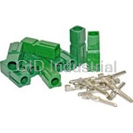
Conn Power PIN 1 POS Crimp ST Cable Mount 1 Terminal 1 Port 1201G1
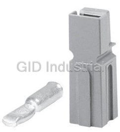
Conn Power SKT 1Power POS ST Cable Mount 1 Terminal 1 Port 1300
Conn Power SKT 1Power POS ST Cable Mount 1 Terminal 1 Port 1300G2
Conn Power SKT 1Power POS ST Cable Mount 1 Terminal 1 Port 1300G3
Conn Power SKT 1Power POS ST Cable Mount 1 Terminal 1 Port 1300G4
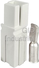
Conn Power SKT 1Power POS ST Cable Mount 1 Terminal 1 Port 1300G5
Request a Quote

The quote request has been received
Close

Facing challenges or have inquiries? Feel free to contact us!
Call Us +1-469-283-2440
What they say about us
FANTASTIC RESOURCE
One of our top priorities is maintaining our business with precision, and we are constantly looking for affiliates that can help us achieve our goal. With the aid of GID Industrial, our obsolete product management has never been more efficient. They have been a great resource to our company, and have quickly become a go-to supplier on our list!
Bucher Emhart Glass
EXCELLENT SERVICE
With our strict fundamentals and high expectations, we were surprised when we came across GID Industrial and their competitive pricing. When we approached them with our issue, they were incredibly confident in being able to provide us with a seamless solution at the best price for us. GID Industrial quickly understood our needs and provided us with excellent service, as well as fully tested product to ensure what we received would be the right fit for our company.
Fuji
HARD TO FIND A BETTER PROVIDER
Our company provides services to aid in the manufacture of technological products, such as semiconductors and flat panel displays, and often searching for distributors of obsolete product we require can waste time and money. Finding GID Industrial proved to be a great asset to our company, with cost effective solutions and superior knowledge on all of their materials, it’d be hard to find a better provider of obsolete or hard to find products.
Applied Materials
CONSISTENTLY DELIVERS QUALITY SOLUTIONS
Over the years, the equipment used in our company becomes discontinued, but they’re still of great use to us and our customers. Once these products are no longer available through the manufacturer, finding a reliable, quick supplier is a necessity, and luckily for us, GID Industrial has provided the most trustworthy, quality solutions to our obsolete component needs.
Nidec Vamco
TERRIFIC RESOURCE
This company has been a terrific help to us (I work for Trican Well Service) in sourcing the Micron Ram Memory we needed for our Siemens computers. Great service! And great pricing! I know when the product is shipping and when it will arrive, all the way through the ordering process.
Trican Well Service
GO TO SOURCE
When I can't find an obsolete part, I first call GID and they'll come up with my parts every time. Great customer service and follow up as well. Scott emails me from time to time to touch base and see if we're having trouble finding something.....which is often with our 25 yr old equipment.
ConAgra Foods