

 Manufacturers
ANDERSON POWER PRODUCTS SBS75GHDLRED

Description
Accessories for Connectors
Part Number
SBS75GHDLRED
Price
Request Quote
Manufacturer
ANDERSON POWER PRODUCTS
Lead Time
Request Quote
Category
Connectors » Connector Accessories
Specifications
Manufacturer
Anderson Power Products
Manufacturers Part #
SBS75GHDLRED
Industry Aliases
SBS75GHDLRED
Sub-Category
Connector Accessories
Packaging
Bag
Factory Pack Quantity
1
Datasheet

Extracted Text
Global Presence Anderson Power Products (Anderson) Has A Global Distribution Network In The Following Countries Along With Many Others: Argentina, Australia, Belgium, Brazil, Canada, Chile, China, Columbia, Denmark, France, Germany, Greece, Hong Kong, Ireland, Israel, Italy, Japan, Mexico, New Zealand, Norway, Peru, Poland, Portugal, Singapore, Slovenia, South Africa, South Korea, Spain, Switzerland, Thailand, Turkey, United Kingdom and United States. Our philosophy is to provide products and services within the trading markets of our customers. We currently serve our worldwide customer base from customer support and manufacturing facilities in Sterling, MA, U.S.A., Warrington UK for European customers, as well as three Asia Pacific facilities: Shenzhen, China, Shatin Hong Kong and Taichung City 407, Taiwan (R.O.C.). Today, as a result of innovative design and development, we have evolved into a valued supplier for a wide variety of markets including Back-up Power, Telecom / Datacom, Alternative Energy Generation & Distribution, Medical Equipment, Defense, and the Material Handling Industries. We have established a reputation for high quality products, on-time deliveries, and excellent customer service. As a result of modern manufacturing techniques and rigorous quality control measures, this assures our customers receive the quality products they deserve. As a global company dedicated to best environmental practice, we have taken steps to meet the RoHS directive for virtually all products. We look forward to the challenges posed by the new technologies of the future and will continue our century long tradition of design excellence and superior customer support to meet customers’ needs. © 2018 Anderson Power Products, Inc. All rights reserved. This catalog or it’s content may be downloaded only for your personal, non-commercial use. Anderson will use reasonable efforts to include accurate and up-to-date content in the catalog. All product information contained in the catalog including ordering information, illustrations, specifications, and dimensions, are believed to be reliable as of the date of publishing, but is subject to change without notice. Anderson makes no warranty or representation as to its accuracy. Content in the catalog may contain technical inaccuracies, typographical errors and may be changed or updated without notice. Anderson may also make improvements and/or changes to the products and/or to the programs described in the content at any time without notice. Current sales drawings and specifications are available upon request. Neither Anderson nor any party involved in creating, producing, or delivering this catalog shall be liable for any direct, incidental, consequential, indirect, or punitive damages arising out of your use of this catalog or any errors or omissions in its content. All product names, including, but not limited to A®, A in circle, Anderson Power Products®, APP®, Powerpole®, SB®, SBE®, SBO®, SBS®, SBX®, SPEC Pak®, Saf-D-Grid®, Power Clip®, Power Drawer®, PowerMod® and the APP Logo are registered trademarks of Anderson Power Products, Inc. Anderson™ is a trademark of Anderson Power Products, Inc. www.andersonpower.com ® SECTION 1 - SB 50 ................................................ 67 ® • Index & Product Selector .............................. 1 - SB120 .............................................. 72 ® • Technical Reference ..................................... 4 - SB 175 ............................................... 77 ® • Glossary ........................................................ 10 - SB350 ............................................... 82 ® ® • Engineering Reference ................................. 12 - SBE 80 / SBO 60 ............................... 87 ® ® - SBE 160 / SBX175 ........................... 92 ® ® SECTION 2 - SBE320 / SBX350 ........................... 98 ® • Powerpole Connectors ............................... 16 - PPMX Auxiliary Holder for ® ® ® - PP15 to PP45 ....................................... 20 SBO , SBE & SBX ..................... 90, 96, 102 ® ® - Powerpole Pak .................................... 23 - SB SMART ....................................... 105 ® - Powerpole PP75 ................................. 32 ® - Powerpole PP120 ............................... 39 SECTION 4 ® - Powerpole PP180 ............................... 43 • Tooling ......................................................... 109 SECTION 5 SECTION 3 • Part Number Page Reference ..................... 115 • Multipole Connectors ........................................ 48 ® - SBS Mini ............................................ 53 ® - SBS 50 & 75 ....................................... 57 ® Powerpole Connector Family Multipole Connector Family Page Number 16 48 Amps (UL) Per Pole Up to 350 Up to 500 Volts (UL) Per Pole Up to 600 Up to 600 Wire Gauge (AWG) 20 - 3/0 16 - 350 mcm Wire Gauge (mm²) 0.75 - 85.0 1.3 - 150 Number of Power Circuits 1 / Stackable 2 - 3 / Not Stackable Ground ● ● Auxiliary ● PCB Mount ● ● Bus Bar ● ● Panel Mount ● ● Blind Mate ● Hot Plug ● ● Touch Safe ● ● Strain Relief ● ● Polarized Housing ● ● Mechanically Keyed ● Latching ● Handle ● Air Supply System ● - 1 - All Data Subject To Change Without Notice www.andersonpower.com Custom Connector Capabilities We specialize in the design and manufacture of high current connection systems to meet specific customer needs. Our expertise in high amperage connections, multiple types of contact technology, and molded plastic insulators allow us to provide durable, high power connections that fulfill the project requirements of OEM’s. We look forward to working with OEM’s on their manufacturing scale projects to provide connector solutions which our current product portfolio may not satisfy. Marketing, Engineering, Quality, Safety Agency, and Manufacturing teams all contribute through the integrated product development process to create and deliver custom connectors that exceed our customers’ needs and meet our high standards. Contact your local customer service representative or regional sales manager to explore how our custom design and manufacturing capabilities can meet your high volume connection needs. | HOW TO USE THIS CATALOG | The information in this catalog is provided in layers to allow you to quickly find the information you are looking for. 1) Selection Guides are featured at the front of the catalog and at the beginning of each product section to enable quick connector selection by electrical attributes and other features. 2) A Technical Reference is provided to give important information common to all connectors in this catalog. Answers to common questions, definitions of terminology, and technical charts are all included. 3) Overviews at the beginning of each product main section describe the similarities and call out common features of products within that section. 4) Introductions to the features and benefits of each product are supplied at the beginning of each sub-product ® ® section (SB 50, SB120, etc). 5) Specifications and Temperature Charts are shown after the main connector components in each sub-product ® ® section to provide detailed technical information (SB 50, SB120, etc). ® ® 6) Tooling Charts are provided at the end of each connector family (SB , SBS etc) to quickly identify the correct tooling. - 2 - All Data Subject To Change Without Notice www.andersonpower.com SECTION 1 Index / Prod. Selector SECTION 1 Index / Prod. Selector | PRODUCT SELECTION WORKSHEET | Prior to selecting an interconnect solution, we recommend you gather the following information. This will aid you in quickly identifying the best product for your particular need. Amps Continuous ________________ max amps at ___________ volts Peak _____________________ max amps ___________ seconds Temperature Operating _____________ Storage ____________ Circuit Definition Number of Circuits: Wire Gauge: Power ____________________ ________________________ Ground ____________________ ________________________ Auxiliary ____________________ ________________________ Other ____________________ ________________________ Application □ PCB to PCB □ Wire to PCB □ Wire to Bus Bar □ Wire to Wire □ Wire to Panel □ Other _______________________________ Mounting Method (if applicable) □ PCB □ Panel □ Blind Mate Contacts □ Mating Cycles _____ □ Individual □ Reeled □ Tin □ Silver □ Gold □ Straight □ Right Angle Other Features □ Hot Plug □ Touch Safe per _______ □ Flame Resistance per ___________ □ IP rating of __________ □ Sequencing □ Strain Relief □ Polarized Housing □ Mechanical Housing Key □ Latching □ Handle □ Other _____________________________________________________________________________________ ____________________________________________________________________________________________ ____________________________________________________________________________________________ NOTES: - 3 - All Data Subject To Change Without Notice www.andersonpower.com | GENERAL APPLICATION NOTES | There are common considerations when using our connectors. Additional considerations may apply based on the particular connector being used, the application, and conditions in which it’s being used. This information is intended to provide a basic understanding and is provided for reference only. Connectors should be assembled and used ac- cording to the equipment and the manufacturer’s instructions, as well as in compliance with local and international electrical codes. The maximum amperage ratings provided in the specifications are based on use of our recommended assembly tooling and the maximum wire size for the connector being used. Amperage ratings are based on not exceeding the maximum operating temperature of the connector housing, factoring in an ambient temperature of 25°C or 77°F. A wire with an appropriate insulation temperature rating should be selected to meet or exceed the total connector temperature (heat rise + ambient). As an example: if the maximum operating temperature for a connector operation is 105°C and the ambient temperature is 25°C, the maximum heat rise attributable to the connector is 105°C - 25°C = 80°C. The expected heat rise based on the connector and wire size used can be estimated using the heat rise charts, but should be confirmed by testing in the specific application with the specific wire to be used. Connector devices are rated or derated by the wiring configuration and the environment. Factors to be considered include: enclosure characteristics, connector housing and wire insulation characteristics, number of wires in an enclosed area such as a raceway or conduit, as well as the ambient temperature. Underwriter Laboratories Inc. amperage ratings are based on not exceeding the maximum operating temperature of the connector housing. This means connectors can be extremely hot when used at the UL amperage ratings. For this reason UL amperage ratings should only be applied to connectors when they are used inside an enclosure not accessible to untrained persons. Canadian Standards Association ratings are based on not exceeding a 30°C temperature rise above ambient temperatures. For this reason CSA amp ratings are a good point of reference for connectors that are user operated. APP does not recommend exceeding a 30°C temperature rise above ambient temperatures for connections accessible during operation to untrained persons. | HOW TO READ TEMPERATURE CHARTS |Temperature rise charts are based on a 25°C ambient temperature. Temperature Rise at Constant Current Charts ® SB 50 Temperature Rise at Constant Current 60 Temperature Rise at Constant Current charts show the associated heat rise ® as a result of applied current to the connector. An example of the SB 50 con- 50 nector Temperature Rise chart is included to follow along with this explana- 40 tion. 30 The chart is based on an ambient temperature of 25°C (77°F room temperature). Accordingly if the temperature °C on the Y axis of the chart is at 20 30°C, the expected total connector temperature would be 55°C. 10 Separate curves are shown for #6, #8, #10, and #12 AWG wire. Interpreting 0 0 10 20 30 40 50 60 70 80 90 the curves, if 50 amps are applied continuously to the connector, the heat rise Amperes Applied will be 23°C for #6, 35°C for #8, 55°C for #10, and #12 wire is not suitable for 6 AWG 8 AWG this amperage. 10 AWG 12 AWG Where T = Temperature, heat rise is expressed as a ΔT°C. T ambient - T (ambient + heat from applied current) = ΔT°C. - 4 - All Data Subject To Change Without Notice www.andersonpower.com SECTION 1 Technical Reference Temperature Rise Above Ambient (°C) SECTION 1 Technical Reference Derating vs. Ambient Temperature Charts ® Derating vs. Ambient Temperature charts show the maximum amperage SB 50 Derating vs. Ambient Temperature capability of a connector at a given ambient temperature. An example of 125 ® the SB 50 connector chart is included to follow along with this explanation. 100 All data points are based on the maximum operating temperature of the connector, most often 105°C or 221°F. Accordingly if the temperature °C 75 on the Y axis of the chart is at 105°C, there is no amperage capability because the connector housing is already at the maximum operating temperature. 50 Separate curves are shown for #6, #8, #10, and #12 AWG wire. 25 Interpreting the curves, at a 75°C ambient temperature the maximum 0 10 20 30 40 50 60 70 80 90 100 amperage capability that can be applied continuously to the connector is: Amperes Applied 58A for #6, 46A for #8, 37A for #10, and 31A for #12 wire. 6 AWG 8 AWG 10 AWG 12 AWG Notes on Temperature Rise Charts Note that these charts are constructed using calculations based on actual test data. For this reason the chart information may vary slightly from the safety agency ratings. Safety agency ratings and compliance with electrical codes take precedent over these charts. The charts are designed to provide a guideline as to the connectors’ capability. Actual results can vary based on the specific wire used, crimp tooling and assembly, as well as the environment the connector is used in. CSA ratings are based on not exceeding a 30°C temperature rise above ambient or a total temperature of 55°C. This is considered the maximum temperature to safely handle a connector at. UL ratings can be based on the operating temperature limit of the connector. Often for our connectors this is 105°C or an 80°C temperature rise above an am- bient temperature of 25°C. To provide a margin of safety, the heat rise charts are limited to a 60°C temperature rise. | COMPATIBLE WIRES | Al Cu Our connectors are designed to be crimped and/or soldered to multi-stranded copper conductor wires only. Alternate conductor materials including aluminum should not be used. Aluminum conductors crimped into our contacts can result in a galvanic reaction occurring between the aluminum wire and the more cathodic metals used in our contacts including copper, tin, silver, and gold. Additionally softer metals like aluminum flow or loosen from crimps much easier than copper. Multi-stranded wire is recommended for all our connectors and is required when crimp terminating wires or when a ® ® connector with flat wiping contact technology is used (such as Powerpole and SB ). Solid wires do not adequately compress and retain in crimp barrels after being crimped. For this reason if solid wire is used, it should be with solder termination only. Solid wires also do not flex and bend as easily as multi-stranded equivalents and can act as a lever arm and impede or alter the natural state of a flat wiping contact in the housing. This impediment or alteration to the flat wiping contact’s natural state can cause intermittency and shorts as well as higher resistance and temperature at a given amperage than is shown in the specifications. Mating and unmating forces may also be impacted. - 5 - All Data Subject To Change Without Notice www.andersonpower.com Ambient Temperature (°C) | DIFFERENT CONTACT TECHNOLOGIES | Flat Wiping: • Same contacts on the “male” and “female” side reduce inventory costs and increase ease of assembly. • Low resistance connection has a large conducting surface and a high normal force in comparison to typical pin and socket contacts. • Sacrificial tip confines damage to non-conducting area when mating or breaking under load. • Raised surface on the mating side of the contacts secures the connector in the mated condition, limiting the need for latching on outer housings. • Over wiping design cleans the mating surface when mating and unmating. - VS - Solid line of electrical Select points of contact. electrical contact. Flat Wiping Technology Pin & Socket Technology Pin & Socket: • Different contacts on male and female sides. Female socket contacts are typically more expensive than the simple geometries of the pin contacts. • Often higher resistance than flat wiping connectors of the same wire size and plating due to the reduced mating surface area and lower normal force. Gold plating often used to compensate and minimize resistance. • Best for compact connection needs such as signal and low power due to static position in housings and symmetrical shape. • Socket contacts can catch and hold debris inside the socket body causing mating problems. | USE OF ANDERSON™ CONNECTORS IN APPLICATIONS EXCEEDING 600V | The approved voltage ratings for our connectors are usually limited by the category under which a safety agency such as UL approves our connector for use. UL typically defers to National Electric Code (NEC) on the voltage limitations for any given device our connector could be used in. For most common applications NEC restricts voltage to a maximum of 600V AC or DC which is what our connector voltage ratings are based on. To achieve UL 1977 approval for a 600V rating, we test our connectors for dielectric withstanding voltage. The connector is tested at 2 times the rated voltage of 600V plus 1000V or 2200VAC for 1 minute. For applications exceeding 600V, UL / NEC / IEC may require application specific review for creepage and clearance resistance. | FREQUENTLY ASKED QUESTIONS | Q: Can I cross mate low and high mating force contacts? A: Yes, however this would not be a connection solution we have tested for safety agency approval. Additionally the contacts may wear at an accelerated rate causing the mating cycle rating to be reduced. The mating and unmating force expected would be somewhere in between the high and low mating force specification. Q: Can I crimp multiple wires into 1 crimp barrel? A: Yes, however this would not be a connection solution we have tested for safety agency approval. Particular care should be used that the bundle of wires do not interfere with the movement of the contact in the housing during mating and unmating (see maximum wire O.D. specification). The total circular mils of all conductor stands should be within + or – 5% of the wire size the contact is intended for. Twist the conductor strands together and crimp using our tooling with range taking capabilities such as the 1368 series. To crimp with other Anderson™ recommended tools, contact customer service for the recommended setting or die and locator combination. - 6 - All Data Subject To Change Without Notice www.andersonpower.com SECTION 1 Technical Reference SECTION 1 Technical Reference Q: Will the crimp tool I have for standard color-coded lugs, Mil Spec contacts, or another connector manufacturer, work for crimping Anderson™ contacts? A: No. Our contacts generally do not conform to standard crimp barrel dimensions used for lugs, Mil Spec contacts, or other connector manufacturers. The tooling recommended by us must be used to ensure the performance designed by us is achieved. Alternate tooling will void our warranties and can affect safety agency approvals. In some instances Mil Spec tools are approved for crimping contacts with the dies and locators recommended by us. See tooling charts for specific instances, or contact customer service for more information. Q: Can metric sized wires be used with Anderson™ contacts? A: Yes. The majority of our crimp tooling recommendations are based on testing and verification we have performed with AWG sized cables. Metric cables of the same or slightly smaller circular mils equivalent to the AWG wire recommended can typically be successfully terminated in our contacts. There is a wire conversion chart at the end of this catalog section that can be used as a reference when converting AWG to mm² sizes. The 1368 series crimp tooling has a range taking capability that produces a reliable crimp with metric equivalents of AWG cables. Please contact customer service for metric tooling recommendations for other Anderson™ crimp tools. Q: Are Anderson™ connectors suitable for use in applications where the voltage exceeds 600V AC/DC? A: Possibly. See “Use of Anderson™ Connectors in Applications Exceeding 600V”, contact customer service with further questions. ® Q: How do Powerpole and Multipole connectors stay securely mated without latches? A: The proven flat wiping technology used in these connectors features a detent or bump in the contact surface along with powerful stainless steel springs that hold the connectors in the mated position. High mating force contacts have a detent that is raised higher than low mating force contacts. The higher the detent, the more force is required to mate and unmate the contacts. In many applications the detent and spring force is enough to securely hold the connectors in the mated position without the need for latches. Latching shells, clips, or other external devices can be used to secure flat wiping connectors in applications where shock, vibration, or cable strain may overcome the inherent force holding the connectors together. Q: How does Anderson’s genderless connector design work to make a mated pair. ® A: Genderless Powerpole and Multipole housings do not have a male(pin) and female(socket) side. For wire-to-wire applications the exact same housings and contacts are used on both sides of the mated pair. If your application calls for wire-to-PCB or wire-to-busbar connections then different contacts and possibly housings will be required on each half (similar to male and female connectors). ® To make a mated pair of Powerpole or Multipole connectors simply assemble the connectors closely following the assembly instructions. After each connector half is fully assembled take one half and flip it over. The two halves will ® mate together. Multi-row Powerpole assemblies will need to be stacked in mirror images of each other to properly ® mate the correct circuits. This information is detailed at the beginning of the Powerpole section. - 7 - All Data Subject To Change Without Notice www.andersonpower.com | TOUCH SAFETY & INGRESS PROTECTION (IP) | UL 1977 Section 10.2: Typically required for applications where the connector is external to the end device and operating over 30V or 200A, where wet conditions may be present (600V category). Testing is performed using a probe that mimics a child’s finger. All features of the connector are tested for live parts in the unmated state (no pressure applied). A smaller 3 mm probe is then applied in the mated state to test for live parts. Note that some applications may require the connector to not expose live parts to the 3 mm probe in the mating interface. IEC 60950: From the standard for Information Technology Equipment Safety, the requirements are harmonized with UL1950. Typically required for commercial and industrial applications where operators may need some degree of protection while accessing or servicing equipment. Testing is performed using a probe that mimics an adult finger. All features of the connector are tested for live parts in the unmated state with 30 N of force applied to the probe. IEC 60529: Standard for Degrees of Protection Provided by Enclosures is harmonized with EN 60529. Protection degree number is assigned to both solids and liquids in that order. For example: a connector with an IP20 rating is protected against fingers, but has no protection against ingress of liquids. We take a conservative approach in rating our connectors against liquid ingress and consider any meaningful water ingress to have a harmful effect. Solids (First Digit) Liquids (Second Digit) Protection Description Protected Against Description Protected Against Degree Not Protected Not Protected 0 Large body part such as Vertically dripping water Duration: 10 minute 1 > 50 mm back of hand (no harmful effect) Water: 1 mm / minute rainfall Pressure: N/A Adult fingers or similarly Tilted 15 degrees up Duration: 10 minute 2 > 12.5 mm sized objects dripping water Water: 3 mm / minute rainfall (no harmful effect) Pressure: N/A Typical screw drivers or Water spray up to 60 Duration: 5 minute 3 > 2.5 mm large wires degree angle Water: 0.7 liter / minute (no harmful effect) Pressure: 80-100 kN/m² Small pointy tools and Water splash from Duration: 5 minute small wires any direction Water: 10 liter / minute 4 > 1 mm (no harmful effect) Pressure: 80-100 kN/m² Complete physical Water jet from any Duration: 3+ minute 5 protection, no functional direction Dust protected Water: 12.5 liter / minute interference from dust (no harmful effect) Pressure: 30 kN/m² @ 3 m distance Complete physical Strong water jet from Duration: 3+ minute Dust sealed protection and sealed 6 any direction Water: 100 liter / minute from dust ingress (no harmful effect) Pressure: 100 kN/m² @ 3 m distance No ingress of water Duration: 30 minute in harmful quantity Water: Immersion 7 when immersed up Pressure: 1 m depth to 1 m depth N/A No ingress of water Duration: Mfg. specified in harmful quantity Water: Immersion 8 when subject to tests Pressure: 1+ m depth. Mfg. specified in excess of condition 7 - 8 - All Data Subject To Change Without Notice www.andersonpower.com SECTION 1 Technical Reference SECTION 1 Technical Reference | PREVENTIVE MAINTENANCE | Damaged connectors, contacts and cables may present hazards, resulting in inefficient battery and charger operation. To avoid these problems, conduct the following maintenance checks at least once annually. If you see any of the following problems, take corrective action immediately. 1. Dirty Connectors ® When engaged and disengaged, the contact surfaces of Anderson SB Connectors “over wipe,” thus providing a self cleaning action. To ensure the continued benefit of this feature, clean the contact surfaces and lubricate the connector. Use a “white” lithium grease, which may be obtained from hardware stores and automotive parts suppliers. 2. Melting Connectors Connector housings overheat and melt for many reasons. To prevent this: A. Examine the crimp between cable and contact. Ensure the crimp tooling recommended by us has been used. Improper crimping, corrosion, and broken wires result in unnecessary resistance causing the contact to heat up. B. Check contact surfaces for signs of “pitting” caused by dirt or disengaging connectors under load. One badly pitted contact, particularly in a connector attached to a battery charger, can lead to pitting on surfaces of other contacts. If not corrected, this can result in an epidemic of bad connectors throughout a fleet of electric vehicles and in chargers and batteries. C. Check to see if batteries are being disconnected while the charger is still on. This causes the contacts to arc at the tips, resulting with progressive pitting and silver removal from tip to crown. If this practice is occurring, discontinue it now to avoid major repairs in the future. 3. Other Conditions If any of the following conditions exist, the connector housing, contact and/or cable should be replaced immediately. A. Housing: Cracks, missing pieces, evidence of excessive heat, discoloration. You may consider replacing the existing housing with a Chemical Resistant equivalent for improved durability against UV rays and common solvents and hydrocarbons. B. Contacts: Pitting, burns, corrosion, excessive wear and cracked crimp barrels, as shown in image “B”. C. Cable: Exposed copper near housing, cracked cable, peeling or frayed insulation. D. Handles: Loose attachment and signs of damage as missing or loose hardware and cracked or broken plastic (Handles should be used for connectors that are hard to reach or move.) E. Cable Clamps: Loose attachments, signs of abraded cable jacket, missing or loose hardware. (Cable clamps should be used to relieve strain on unmounted cable.) Uncrimped Good Damaged Contact Contact B A Damaged Housing Good Condition - 9 - All Data Subject To Change Without Notice www.andersonpower.com Amp / Ampere: Measurement increment of electric current. Flammability: The measure of a material’s ability to support combustion. Abbreviated as “I”. Often tested per UL94. Applicator: A semi-automatic termination machine consisting of an Flat Wiping: The sliding action which occurs when contacts are mated. upper and lower half that is used to crimp contacts onto wire. Used in Wiping has the effect of removing small amounts of contamination from conjunction with an electrical/ mechanical press. the contact surfaces, thus establishing better conductivity. AWG: American Wire Gauge. A standard system for designating wire Genderless: See “Hermaphroditic” diameters. Heat Rise: Temperature rise associated with the electrical load applied Blindmate: To join two connector halves in a normal engaging mode to a mated connection. without visual orientation. Hermaphroditic (Genderless) Connector: A connector in which both Busbar: Three dimensional constructions enabling electrical distribution mating members are exactly alike at their mating face. There are no of current in power electronic modules. Typically constructed of cop- male or female members, but designs provide correct polarity. per, busbars are most frequently used in power dense applications where the busbar offers a cost or space savings over wire. Hot Plug / Hot Swap: Live connector insertion / extractions. Color Coding: A system of identification for terminals and related devices. IEC: International Electrotechnical Commission, a standard writing organization. Contact Resistance: The electrical resistance of metallic surfaces at their interface in the contact area under specified conditions when Insulation Resistance: Ratio of applied voltage to the total current carrying a specified test current. between the two electrodes in contact with a specific insulation. Contact Retention: Minimum axial load in either direction which a IP: Ingress Protection, a standard per IEC 60529 for measurement of contact must withstand while remaining firmly fixed in its normal position ingress for solids and liquids into an enclosure. within a housing. Locator / Positioner: Device for positioning contacts into crimping dies. Crimp Retention: The axial load which a contact can withstand without separation from the wire. Make-First / Break-Last (Premate): Sequencing of contact(s) so that they engage prior to the main power contacts. Typically used Crimp Termination: A connection in which a metal sleeve is secured for ground / positive earth / neutral positons as a protective measure to a conductor by mechanically deforming the sleeve with presses or against excess currents, short-circuits, and ground faults. automated crimping machines, eliminating the need for solder. Not suitable for solid (non-stranded wires). Make-Last / Break-First (Postmate): Sequencing of contact(s) so that they engage after the main power contacts. Typically used for signal or CSA: Canadian Standards Association, a safety standard writing and auxiliary power positions to ensure communications are not started or testing organization. power circuits switched on until the power contacts are fully engaged. Cycle Controlled: To determine if repetitive on/off conditions result Mating Force: Force required to join two connector halves in a normal in degrading the contact system which may lead to failures such as engaging mode. “thermal run away”. Modular: Refers to similar parts or modules used as building blocks. A Detent: A bump or raised section projecting from the surface of a contact modular connector is one in which similar or identical sections can be for keeping the contact in position relative to another and released by assembled together to provide the appropriate connector type or size greater force. for the application. Dielectric Strength (Withstanding Voltage): The highest potential Ohms: Measurement increment of resistance. difference (voltage) that an insulation material of given thickness can withstand for a specified time without occurrence of electrical breakdown Operating Temperature Range: Connector temperature rating through its bulk. established by materials used, plastic, finish, and the base metal. Applying an electrical load will result in a temperature rise that is Finger Proof: A connector intended for usage external to the end additive to the operating ambient. equipment shall have live parts protected against exposure to contact by persons when assembled, installed, and mated as intended, as PCB: Acronym for Printed Circuit Board. determined by UL Articulated probe. - 10 - All Data Subject To Change Without Notice www.andersonpower.com SECTION 1 Glossary SECTION 1 Glossary Spring Loaded: A means of providing contact normal force with the Polarization: A technique of eliminating symmetry so that parts may use of a mechanical spring. only be mated one way. Storage Battery: A voltaic battery consisting of two or more storage Pulse (Surge) Current: Highest instantaneous current that will run cells. Energy is accumulated by chemical activity in the charging through a system. process and released on demand in the form of electric current. REACH: The European Community Regulation on chemicals and their Strain Relief: A means of termination or installation that reduces the safe use. It deals with the Registration, Evaluation, Authorization and transfer of mechanical stress from the conductor. Restriction of Chemical substances. Termination: Means of joining contacts to a conductor. Reducing Bushing: Separate tubular sleeve used to downsize the diameter of a crimp barrel to accept a smaller size wire. Touch Safe: See “Finger Proof” Reeled Contacts: Contacts attached to a feeder strip for use in a high Turret / Positioner: See “Locator” volume crimping tool. TUV: The TÜV Rheinland Group is provider of technical services that Resistance: The opposition to the passage of an electric current certifies products to standards written by other organizations. through that element. Abbreviated as “R”. UL: Underwriters Laboratory, a safety standard writing and testing RoHS: Restriction of Hazardous Substances Directive. The European organization. directive on the restriction of the use of certain hazardous substances in electrical and electronic equipment. Volts: Measurement increment of electric potential. Abbreviated as “E”. Sacrificial Tip: An area of a contact system that absorbs electric arching VDE: A German standard writing and testing organization responsible to limit damage to the actual mating surface of the contacts. standards and safety specifications covering the areas of electrical engineering, electronics and information technology. Self-Wiping: The sliding action which occurs when contacts are mated. Wiping has the effect of removing small amounts of contamination Watt: Measurement increment of electric power. Abbreviated as “W”. from the contact surfaces, establishing better conductivity. - 11 - All Data Subject To Change Without Notice www.andersonpower.com | CONVERSION CHART FOR AMERICAN WIRE GAUGE TO METRIC SYSTEM | Approximate Approximate AWG Metric Circ. Equivalent Wire Diameter AWG Metric Circ. Equivalent Wire Diameter Size mm² Mils Circ.Mils in. mm Size mm² Mils Circ.Mils in. mm - 0.5 - 937 0.032 0.81 1/0 - 106mcm* - 0.373 9.46 20 - 1020 - 0.036 0.91 2/0 - 133mcm* - 0.419 10.60 - 0.75 - 1480 0.039 0.99 - 70 - 138.1mcm 0.430 10.90 18 - 1620 - 0.046 1.16 3/0 - 168mcm* - 0.471 12.00 - 1 - 1974 0.051 1.30 - 95 - 187.5mcm 0.504 12.80 16 - 2580 - 0.051 1.29 4/0 - 212mcm* - 0.528 13.40 - 1.5 - 2960 0.063 1.60 - 120 - 237.8mcm 0.567 14.40 14 - 4110 - 0.073 1.84 - - 250mcm - 0.575 14.60 - 2.5 - 4934 0.081 2.06 - 150 300mcm - 0.630 16.00 12 - 6530 - 0.092 2.32 - - 350mcm - 0.681 17.30 - 4 - 7894 0.102 2.59 - 185 - 365.1mcm 0.700 17.80 10 - 10380 - 0.116 2.93 - - 400mcm - 0.728 18.50 - 6 - 11840 0.126 3.21 - 240 - 473.6mcm 0.801 20.30 8 - 16510 - 0.146 3.70 - - 500mcm - 0.814 20.70 - 10 - 19740 0.162 4.12 - 300 - 592.1mcm 0.891 22.60 6 - 26240 - 0.184 4.66 - - 600mcm - 0.893 22.70 - 16 - 31580 0.204 5.18 - - 700mcm - 0.964 24.50 4 - 41740 - 0.232 5.88 - - 750mcm - 0.999 25.40 - 25 - 49340 0.260 6.60 400 - 789.4mcm 1.026 26.10 2 - 66360 - 0.292 7.42 - - 800mcm - 1.032 26.20 - 35 - 69070 0.305 7.75 - 500 986.8mcm 1.152 29.30 1 - 83690 - 0.332 9.43 - - 1000mcm - 1.153 29.30 - 50 - 98680 0.365 9.27 - 625 - 1233.7mcm 1.287 32.70 * Rounded for simplicity NOTE: The above wire diameters and circular mils are based on an average of the most commonly available wires. The wire manufacturer’s specification should be referenced for information specific to the wire being used. - 12 - All Data Subject To Change Without Notice www.andersonpower.com SECTION 1 Engineering Reference SECTION 1 Engineering Reference | VOLTS • AMPS • OHMS • WATTS CONVERSION | E E E I WR R I W W W I² R R I² I W E² E² IR E W R Volts = Watts x Ohms Ohms = Volts Watts = Volts x Amps Amperes = Volts Ohms Amps Watts Ohms = Watts ² Amperes = Watts Watts = Amps x Ohms Volts = Amps Amps² Ohms Amperes = Watts Ohms = Volts² Watts = Volts² Volts = Amps x Ohms Volts Watts Ohms Wattage Varies Directly as a Ratio of Voltages Squared. E² W² = W¹ x² E¹ Total Watts 3 Phase Amperes = Volts x 1.732 - 13 - All Data Subject To Change Without Notice www.andersonpower.com | STANDARD TO METRIC CONVERSIONS | Approximate Conversions Approximate Conversions From: SI / Metric Units From: Standard / US Customary To: Standard / US Customary To: SI / Metric Units When When You You Multiply Multiply Symbol Know To Find Symbol Symbol To Find Symbol By Know By LENGTH LENGTH in inches 25.4 millimeters mm mm millimeters 0.039 inches in ft feet 0.305 meters m m meters 3.28 feet ft AREA AREA 2 2 square square mm millimeters 0.0016 square in 2 2 in inches 645.2 millimeters mm inches 2 square 2 m square 10.764 square feet ft 2 2 ft square feet 0.093 meters m meters VOLUME VOLUME fluid mL milliliters 0.034 fluid fl oz fl oz ounces 29.57 milliliters mL ounces L liters 0.264 gallons gal gal gallons 3.785 liters L cubic 3 3 m cubic 35.314 cubic feet ft 3 3 ft cubic feet 0.028 meters m meters MASS MASS oz ounces 28.35 grams g g grams 0.035 ounces oz lb pounds 0.454 kilograms kg kg kilograms 2.202 pounds lb TEMPERATURE TEMPERATURE o o o o Fahrenheit (F-32) x 5 / Celsius F C C Celsius 1.8C + 32 Fahrenheit F 9 or (F-32) / 1.8 FORCE and PRESSURE or STRESS FORCE and PRESSURE or STRESS lbf poundforce 4.45 newtons N N newtons 0.225 poundforce lbf 2 2 lbf/in poundforce 6.89 kilopascals kPa kPa kilopascals 0.145 poundforce lbf/in per square per square inch inch - 14 - All Data Subject To Change Without Notice www.andersonpower.com SECTION 1 Engineering Reference SECTION 1 Engineering Reference | NOTES | - 15 - All Data Subject To Change Without Notice www.andersonpower.com ® ® Powerpole Connectors - PP15 to PP180 This versatile connector series invented by Anderson Power ® Products (APP ) meets a wide range of power connection ® needs. There are four basic housing sizes in the Powerpole product family that allow specific amperage or wire size needs ® to be filled in the most compact footprint. Powerpole can handle up to 350 amperes per pole and accommodate wire ranges of #20 AWG (0.75 mm²) to 3/0 (70 mm²). A wide range of colored housing options can be stacked together to create a proven reliable custom connector. These housings can be used with different contacts to create wire-to-wire, wire-to- ® board, or wire-to-busbar connections. The Powerpole connector combines high quality materials and a cost effective innovative design to allow powerful versatility. Stackable Modular Housings Available in four sizes to right size your connection need Color Coded Housings Help ensure that connectors are assembled and mated correctly Genderless Housings Provide simplified assembly and minimize the number of components Low Resistance Connection Silver or tin plated contacts inside housings that strongly force the contacts together Self Securing Design Stainless steel springs create a robust force between the contacts that holds the con- nector in the mated condition, Hot Plugging AC or DC but allows it to be quickly dis- Contacts feature a sacrificial connected tip that allow high current circuit interrupt Connection Versatility Contacts for wire, PCB, or busbar all fit into the same housings - 16 - All Data Subject To Change Without Notice www.andersonpower.com SECTION 2 ® Powerpole Family SECTION 2 ® Powerpole Family ® | POWERPOLE FAMILY SELECTION GUIDE | ® Powerpole Size PP15 to 45 Page # PP75 Page # PP120 Page # PP180 Page # Connector Types Standard 20 Standard 32 Standard 39 Standard 43 Finger Proof 20 Locking 32 Busbar 44 PCB 21 Busbar 33 Ground 20 PCB 33 Power Pak 23 Amps (UL) Per Pole 0 to 55 120 240 350 Volts (UL) Per Pole 600 600 600 600 Wire Gauge (AWG) 20 - 10 16 - 6 6 - 1/0 10 - 3/0 Wire Gauge (mm²) 0.75 - 6.0 1.3 - 13.3 13.3 - 53.5 5.3 - 85.0 Number of Power Circuits 1 / Stackable 1 / Stackable 1 / Stackable 1 / Stackable Ground ● PCB Mount ● ● Busbar ● ● Panel Mount ● ● ● ● ® Blind Mate Powerpole Pak Hot Plug ● ● ● ● Touch Safe ● Polarized Housing ● ● ● ● ® Latching Powerpole Pak ® Powerpole Pak Strain Relief Actual Size - Connector Half ® ............................................................... Powerpole Housings .......................................................... PP15/45 PP75 PP120 PP180 - 17 - All Data Subject To Change Without Notice www.andersonpower.com Column 3 Column 2 Column 1 Powerful Versatility - Create Your Own Custom Connector from Durable Proven Components ® Powerpole connectors can be easily customized to each power connection need. Choose from a wide range of colored housings and stack them together into a multiple position connection. Durable silver or tin plated contacts crimp and poke into housings and are available for a broad range of wire sizes. PCB and busbar contacts can also be simply snapped into place using the same housings. Pre-mate ground / power housings and contacts can be used for safety or sequencing and stack along with standard housings. ® How to Create Mating Blocks of Stacked Powerpole Connectors A Single Row Assembly such as the 1x3 shown below will mate to itself. If an assembly has more than one row such as the Two Row Assembly 2x1 shown below, then a different mirror image mating assembly is required. Single Row Assembly 1x3 Two Row Assembly 2x1 To Create a Mirror Image Mating Assembly: When mating blocks are viewed with their hoods in the respective orientation (down or up), the column position of connectors is unchanged. The rows themselves are mirror images of each other. So in the below example, what is column 1 on side A, is column 3 on side B. Side A Hood Down Side B Hood Up Hood Up C B A A B C Hood Down F E D D E F I H G G H I - 18 - All Data Subject To Change Without Notice www.andersonpower.com Column 1 Column 2 Column 3 SECTION 2 ® Powerpole Family SECTION 2 ® Powerpole Family Use the Same Housings for Wire, PCB, or Busbar Connections ® The Powerpole connection system allows the same housings to hold different contacts for terminating to wire, ® printed circuit boards, or busbars. See some of the many ways Powerpole components can be assembled to create a custom connection solution. Wire-to-Wire Wire-to-PCB Wire-to-Busbar - 19 - All Data Subject To Change Without Notice www.andersonpower.com ® Powerpole Connectors ® PP15-45 series are the smallest Powerpole housings. They can - PP15 to PP45 : be used for wire-to-wire or wire-to-board applications. Wire sizes up to 55 Amps from #20 AWG (0.75 mm²) to #10 (6 mm²) offer power capabilities up to 55 amps per pole. Finger proof housings and the ability to incorporate first-mate last-break ground connectors enhance the ® capabilities of this Powerpole series. High Power Density • Up to 55 amps in a compact footprint Wire-to Wire & Wire-to-Board Configurations • Wire & PCB contacts can be used in the same housings Finger Proof Housings Available • Protects against accidental contact with live circuits | PP15-45 ORDERING INFORMATION | PP15-45 Finger Proof Housings PP15-45 Finger Proof & Standard & Ground Improved on the original APP design by adding ribs to mating interface to Housing Dimensions protect against accidental contact with live circuits. Meets the requirements of UL1977 section 10.2 and is rated IP20. Will not mate with standard housings. Front View [ 7.9 ] 0.31 Description ------------ Part Numbers ------------ Mated Length [ 24.6 ] Finger Proof 0.97 Minimum Quantity ... 2,500 200 ..... Rib Feature Red 1327FP-BK 1327FP [ 7.9 ] [ 8.4 ] Green 1327G5FP-BK 1327G5FP 0.31 0.33 Black 1327G6FP-BK 1327G6FP [ 41.2 ] White 1327G7FP-BK 1327G7FP 1.62 Blue 1327G8FP-BK 1327G8FP Yellow 1327G16FP-BK 1327G16FP PP15-45 Standard Housings This original housing design has an open interface and is available in a wide array of colors. Will not mate with finger proof housings. Description ------- Part Numbers ------ Minimum Quantity ... 2,500 200 ... Red 1327-BK 1327 Green 1327G5-BK 1327G5 Black 1327G6-BK 1327G6 White 1327G7-BK 1327G7 Blue 1327G8-BK 1327G8 Yellow 1327G16-BK 1327G16 Orange 1327G17-BK 1327G17 Gray 1327G18-BK 1327G18 Brown 1327G21-BK 1327G21 Pink 1327G22-BK 1327G22 Purple 1327G23-BK 1327G23 45A Premate Ground Housings - (for use with ground contacts only) Green housings are keyed to prevent accidental mating with ® standard or finger proof Powerpole housings. Description ------ Part Numbers ----- Minimum Quantity ... 2,500 200 ... Green 1827G1-BK 1827G1 - 20 - All Data Subject To Change Without Notice www.andersonpower.com SECTION 2 ® Powerpole PP15 to 45 SECTION 2 ® Powerpole PP15 to 45 PP15-45 Tin Plated Power Contacts Open Barrel Contact Offer cost effective performance up to 1,500 mating cycles. See specifications and temperature charts for amperage ratings by wire size. Dimensions [ 3.6 ] [ 3.6 ] 0.14 Mating Loose Piece Reeled - A - 0.14 Barrel AWG mm² Force -------- Part Numbers ------- inches mm [ 17.2 ] Minimum Quantity ....................................... 200 5,000 ......................... [ 6.4 ] 0.68 Open 14 to 10 K* 2.1 to 5.3 High 269G3-LPBK 269G3 0.21 5.33 0.25 Open 14 to 10 K* 2.1 to 5.3 Low 261G2-LPBK 261G2 0.20 5.08 Open 14 to 10 SF* 2.1 to 6.0 High 201G1H-LPBK 201G1H 0.24 6.10 A Open 14 to 10 SF* 2.1 to 6.0 Low 200G1L-LPBK 200G1L 0.24 6.10 Open 16 to 12 1.3 to 3.3 High 269G1-LPBK 269G1 0.18 4.57 Open 16 to 12 1.3 to 3.3 Low 261G1-LPBK 261G1 0.18 4.57 Open 20 to 16 0.52 to 1.3 High 269G2-LPBK 269G2 0.16 4.06 Open 20 to 16 0.52 to 1.3 Low 262G1-LPBK 262G1 0.16 4.06 K* - For #10 AWG class K stranded wire or smaller. For larger wires use superflex contacts. SF*- Indicates wires with high stranding such as Super Flex. PP15-45 Silver Plated Power Contacts Open Barrel Contact Maximize performance by offering up to 10,000 mating cycles and are recommended for circuit interrupt or hot plug applications. See specifications and temperature charts for amperage ratings by wire size. Only closed [ 17.27 ] [ 6.35 ] barrel contacts are suitable for soldering. 0.68 0.25 Dimensions Mating Loose Piece Reeled - A - - B - [ 3.81 ] A 0.15 Barrel AWG mm² Force ------- Part Numbers -------- Part Numbers inches mm inches mm Minimum Quantity .......................................... 5,000 200 5,000 ................................................. Open 14 to 10 K* 2.1 to 5.3 Low - 261G3-LPBK 261G3 0.20 5.08 - - Open 14 to 10 SF* 2.1 to 6.0 Low - 200G3L-LPBK 200G3L 0.24 6.10 - - Closed Barrel Contact Open 20 to 16 0.52 to 1.3 Low - 262G2-LPBK 262G2 0.16 4.06 - - Closed 16 to 12 1.3 to 3.3 Low 1331-BK 1331 - 0.15 3.81 0.10 2.54 [ 16.26 ] [ 7.35 ] Closed 20 to 16 0.52 to 1.3 Low 1332-BK 1332 - 0.12 3.05 0.07 1.78 0.64 0.29 B K* - For #10 AWG class K stranded wire or smaller. For larger wires use superflex contacts. [ 3.81 ] A SF*- Indicates wires with high stranding such as Super Flex. 0.15 45A Premate Ground Wire Contacts - (for use with ground housing only) Tin or silver plated contacts are rated for ground or power. Hand tools are available for loose piece Open Barrel Premate Contact contacts. Reeled contacts can be used with high volume press and applicator tooling. Tin contacts are rated for up to 1,500 mating cycles. Silver contacts are rated up to 10,000 mating cycles. [ 3.6 ] [ 19.1 ] 0.14 0.75 Reeled [ 6.4 ] Mating Loose Piece Part 0.25 Type AWG mm² Force - Part Numbers - - Numbers - [ 6.1 ] Minimum Quantity ............................................. 200 5,000 ..... 0.24 Open, Tin 14 to 10 2.1 to 6.0 Low 1830G1-LPBK 1830G1 [ 6.1 ] Open, Silver 14 to 10 2.1 to 6.0 Low 1830G2-LPBK 1830G2 0.24 25A Right Angle PCB Contacts Tin Plated Suitable for right angle applications up to 25A per pole. Tin plating enhances solderability. Cannot be mixed with 45A PCB contacts. For mating with wire contacts only. Dimensions Mating Loose Piece - A - - B - Row Force ------- Part Numbers ------- inches mm inches mm A Minimum Quantity ... 1,000 100 ................................................... [ 9.9 ] Top Low 1377G1-BK 1377G1 0.59 14.80 1.52 38.60 0.39 High 1317G1-BK 1317G1 Bottom Low 1377G2-BK 1377G2 0.29 7.20 1.36 34.50 B High 1317G2-BK 1317G2 Top Low 1377G11-BK 1377G11 0.59 14.80 1.21 30.70 Use mounting staples with right angle contacts High 1317G11-BK 1317G11 (see accessories). Bottom Low 1377G12-BK 1377G12 0.29 7.20 1.01 25.70 See website for PCB layout drawing. High 1317G12-BK 1317G12 25A Vertical PCB Contacts Tin Plated For mating with wire contacts only. Suitable for vertical applications up to 25A per pole, tin plating enhances solderability. Dimensions Mating Loose Piece - A - Force ---------------- Part Numbers --------------- inches mm Minimum Quantity .... 1,000 100 ....................... Low 1377G3-BK 1377G3 2.22 56.40 [ 3.1 ] High 1317G3-BK 1317G3 2.22 56.40 0.12 A Low 1377G4-BK 1377G4 1.76 44.70 Housing end High 1317G4-BK 1317G4 1.76 44.70 Low 1377G13-BK 1377G13 1.17 29.70 High 1317G13-BK 1317G13 1.17 29.70 - 21 - All Data Subject To Change Without Notice www.andersonpower.com 45A Right Angle and Vertical PCB Contacts Tin Plated [ 36.5 ] Vertical Suitable for right angle or vertical applications up to 45A per pole. Tin plating 1.44 [ 28.6 ] enhances solderability. Right angle contacts cannot be mixed with 25A PCB 1.13 contacts. For mating with wire contacts only. [ 29.7 ] [ 5.8 ] [ 5.1 ] 1.17 [ 16.3 ] Loose Piece 0.23 0.20 REF 0.64 Description ----------- Part Numbers ----------- PP15/45 Housings [ 7.9 ] [ 7.9 ] Minimum Quantity ............. 1,000 100 .................... (1327 Series) 0.31 0.31 Vertical 3-5911P1 1335G1 TYP Right Angle Contact TYP Right Angle Bottom Row 3-5912P1 1336G1 Horizontal (bottom) Use mounting staples with right angle Cat.No. 1336G1 Right Angle Top Row 3-5913P1 1337G1 Right Angle Contact contacts (see accessories). Horizontal (top), Cat.No. 1337G1 45A Premate Ground PCB Contacts Right angle contacts are suitable for power or ground. Use to mate with 45A [ 45.3 ] [ 7.9 ] ground wire contacts. Tin plated contacts are rated up to 1,500 mating cycles. 1.78 0.31 TYP [ 41.2 ] [ 14.7 ] Can be used with other 45A PCB connectors in the bottom row. 1.62 [ 8.4 ] 0.578 0.33 TYP Mating Loose Piece [ 5.6 ] Pre-mate wire Force ------- Part Numbers ------- 0.22 connector [ 3.6 ] [ 7.9 ] Minimum Quantity ................... 1000 100 .... 0.14 0.31 [ 28.1 ] PCB, Bottom Row Low 3-5952P1 1836G1 1.11 Mated Pair | PP15-45 ULTRASONICALLY BONDED ASSEMBLIES | Assemblies feature housings that are ultrasonically welded to create a one piece connector unit using an APP special process. After welding, retaining pins are ® no longer required to secure the stacked housings to each other. This allows Powerpole 15-45 connectors to be used as a durable one piece connector header. Contact customer service for configurations not shown below. Single Row 1x2 Assemblies Housings with Housings with 45A Vertical 45A Right Angle Color & Type Circuit Description Housings Only PCB Contacts PCB Contacts Position Matrix Minimum Quantity ................................ 500 500 500 ..... 1 2 DC 2 Wire Standard Housings ASMPP30-1X2-RK ASMPV45-1X2-RK ASMPR45-1X2-RK RED / STD BLK / STD DC 2 Wire Reverse Standard Housings ASMPP30-1X2-KR ASMPV45-1X2-KR ASMPR45-1X2-KR BLK / STD RED / STD DC 2 Wire Finger Proof ASMFP30-1X2-RK ASMFV45-1X2-RK ASMFR45-1X2-RK RED / FP BLK / FP DC 2 Wire Finger Proof Reverse ASMFP30-1X2-KR ASMFV45-1X2-KR ASMFR45-1X2-KR BLK / FP RED / FP Single Row 1x3 Assemblies Housings with 45A Right Angle Color & Type Circuit Description Housings Only PCB Contacts Position Matrix Minimum Quantity ................................ 500 500 ..... 1 2 3 DC 2 Wire Finger Proof with Ground ASMFP30-1X3-KER ASMFR45-1X3-KER BLK / FP GRN / GND RED / FP AC Single Phase Finger Proof ASMFP30-1X3-KEW ASMFR45-1X3-KEW BLK / FP GRN / GND WHT / FP Two Row 2x1 Assemblies Housings with Housings with 45A Vertical 45A Right Angle Color & Type Circuit Description Housings Only PCB Contacts PCB Contacts Position Matrix Minimum Quantity ................................ 500 500 500 .... 1 2 DC 2 Wire Finger Proof ASMFP30-2X1-KR ASMFV45-2X1-KR ASMFR45-2X1-KR BLK / FP RED / FP DC 2 Wire Finger Proof Mate ASMFP30-2X1-RK ASMFV45-2X1-RK ASMFR45-2X1-RK RED / FP BLK / FP Two Row 2x2 Assemblies Housings with Housings with 45A Vertical 45A Right Angle Color & Type Circuit Description Housings Only PCB Contacts PCB Contacts Position Matrix Minimum Quantity ................................ 500 500 500 ..... 1 2 3 4 AC 3 Phase, 3 Wire Finger Proof ASMFP30-2X2-KRWE N/A N/A BLK / FP RED / FP WHT / FP GRN / GND AC 3 Phase, 3 Wire Finger Proof Mate ASMFP30-2X2-WEKR N/A ASMFR45-2X2-WEKR WHT / FP GRN / GND BLK / FP RED / FP 1 2 1 Hood Up 3 4 1 2 1 2 3 2 Single Row 1x2 Assembly Single Row 1x3 Assembly Two Row 2x1 Assembly Two Row 2x2 Assembly Type STD = Standard Housing FP = Finger Proof Housing GND = Ground Housing - 22 - All Data Subject To Change Without Notice www.andersonpower.com SECTION 2 ® Powerpole PP15 to 45 SECTION 2 ® Powerpole Pak ® Powerpole Pak Connectors - PP15 to PP45 ® Powerpole Pak connector shells enclose stacked groupings of PP15-45 sized housings in a durable black shell for a finished connector appearance and additional features. Inline, panel mount, and blindmate configurations Plug shell with latch are available. Plug shells offer the option of integral latches and strain relief to help secure your connection. Snap-in • Package Groupings of PP15-45 Connectors Provides a finished appearance while protecting the individual connectors with an outer shell Blindmate • Inline, Panel Mount, “T” or Blindmate Configurations Allows one connection system to meet multiple needs T-Pak Plug shell • Optional Latching and Strain Relief without latch Secures your connection and wires ® For environmentally sealed connector shells to hold Powerpole ® 15-180 connectors, see SPEC Pak product series on our website, www.andersonpower.com ® Powerpole housings and contacts are sold separately. ® | POWERPOLE PAK ORDERING INFORMATION | See page 20 for ordering information. Plug Shell without Latch Can mate inline with other plug shells with or without latches, or mate to a panel ® mount receptacle. For use with Powerpole wire connectors only. Cable Clamp [ 53.09 ] and Hardware Pak or Retaining Pins must be ordered separately. [ 21.59 ] 2.09 Dimensions 0.85 - A - A Description -------------- Part Numbers -------------- inches mm Minimum Quantity ... 1,000 500 25 ............................. [ 49.28 ] Black, 2-4 Poles 1461G1-BK - 1461G1 1.24 31.50 1.94 Retaining Pin Black, 5-6 Poles - 1461G2-BK 1461G2 1.56 39.62 Side View Top View Black, 7-8 Poles - 1461G3-BK 1461G3 1.87 47.50 NOTE: Retaining pins are used to secure and position ® Powerpole housings in one of three positions in plug shells. Max wire O.D. for 2-4 pole plug shells is 0.60 inches [15.2mm²]. Plug Shell with Latch For all other plug shells is 0.63 inches [ 16.0 mm²]. Can mate inline with other plug shells without latches, or mate to a panel mount receptacle. For use ® with Powerpole wire connectors only. Cable Clamp and Hardware Pak or Retaining Pins must be ordered seperately. Side View Dimensions [ 21.59 ] - B - - C - - D - 0.85 Description ------------- Part Numbers -------------- inches mm inches mm inches mm B Minimum Quantity ..... 1,000 500 25 ................................................................................ Black, 2-4 Poles 1460G1-BK - 1460G1 1.94 49.28 2.25 57.15 1.24 31.50 Black, 5-6 Poles - 1460G2-BK 1460G2 1.94 49.28 2.25 57.15 1.56 39.62 Top View Black, 7-8 Poles - 1460G3-BK 1460G3 1.94 49.28 2.25 57.15 1.87 47.50 C Black, 9-10 Poles - 1460G4-BK 1460G4 2.51 63.75 2.82 71.63 1.84 46.74 D Retaining Pin - 23 - All Data Subject To Change Without Notice www.andersonpower.com Plug Shell with Latch & Non-Conductive Strain Relief [ 21.5 ] ® New 2X3 Powerpole Pak offers an improved ergonomic shell for easier latch operation as 0.85 well as a plastic, non-conductive strain relief. The new strain relief can accommodate up to a 6 conductor #10 AWG cable. Can mate to a panel mount receptacle. For use with ® Powerpole wire connectors only. Cable Clamp and Hardware Pak or Retaining Pins [ 81.5 ] must be ordered separately. To be used with 115G23 cable clamp only. 3.21 [ 73.5 ] 2.90 Description -------- Part Numbers ------- Minimum Quantity .. 1,000 25 ... Black, 5-6 Poles 1460G23-BK 1460G23 NOTE: Max wire O.D. for 1460G23 is 0.80 inches [ 51.4 ] [ 26.1 ] [20.3 mm²]. 2.02 1.03 Snap-in Receptacle Shell Mate to plug shells with or without latches, or mate to another panel mount receptacle to create a bulkhead to ® bulkhead connection. For use with Powerpole wire or PCB connectors. Order the number of retaining pins for each receptacle as shown below separately. Number of Dimensions Knock Out Size Retaining Pins - E - - Width - [ 1.78 ] Description ---------------- Part Numbers ---------------- to Order inches mm inches mm [ 19.56 ] 0.07 Minimum Quantity ... 1,000 500 25 ............................................................................... [ 27.94 ] 0.77 Black, 2-4 Poles 1470G1-BK - 1470G1 1 1.50 38.10 1.25 31.75 1.10 Black, 5-6 Poles - 1470G2-BK 1470G2 2 1.88 47.75 1.62 41.15 E Black, 7-8 Poles - 1470G3-BK 1470G3 3 2.13 54.10 1.88 47.75 Black, 9-10 Poles - 1470G4-BK 1470G4 4 2.44 61.98 2.19 55.63 * Height = [25.4 mm] 1.0 in. Retaining Pin NOTE: Retaining pins are used to secure and ® position Powerpole housings in one of two Cable Clamp & Hardware Pak positions in receptacle shells. Includes cable clamp, 2 screws, and required amount of retaining pins for each configuration. Screw Head Cable Description Type Type ------------ Part Numbers ------------ Retaining Pin Minimum Quantity ................................... 1,000 500 25 ... 2-4 Poles Straight Slot Bundled 115G1-BK - 115G1 5-6 Poles Straight Slot Bundled 115G2-BK - 115G2 Cable Clamp 7-8 Poles Straight Slot Bundled 115G3-BK - 115G3 With Screws 9-10 Poles Straight Slot Bundled - 115G4-BK 115G4 2-4 Poles Philips Bundled 115G7-BK - 115G7 Plug Shell Without Latch Shown 5-6 Poles Philips Bundled 115G8-BK - 115G8 Shell, housing and contacts are sold separately. Cable Clamp & Hardware Pak Includes 2 cable clamp halves, 2 screws and 2 retaining pins. To be used with 1460G23 Plug Shell only. Screws Retaining Screw Head Cable Pins Description Type Type ------ Part Numbers ------ Minimum Quantity ............................…… 1,000 25 5-6 Poles Philips Bundled 115G23-BK 115G23 Clamp Retaining Pin Flexible Conduit Clamp & Hardware Pak Includes cable clamp, 2 screws, and need amount of retaining pins for each configuration. Conduit Clamp Description - Part Number - With Screws Minimum Quantity ...... 100 ...... 2-4 Poles 110G10 Plug Shell With Latch Shown Shell, housing and contacts are sold separately. Retaining Pin for Snap-in Receptacle Order the number of retaining pins for each receptacle shown in the Snap-in Receptacle Shell ordering information. Pins are also required for the plug side when the Cable Clamp & Hardware Pak is not ordered. Description ----- Part Number ------ Minimum Quantity ..... 1,000 100 ... Shell and housing are Retaining Pin 110G9-BK 110G9 sold separately. - 24 - All Data Subject To Change Without Notice www.andersonpower.com SECTION 2 ® Powerpole Pak SECTION 2 ® Powerpole Pak Blindmate Pak Connector [ 88.6 ] 3.49 [ 50.8 ] Ideal for panel to panel, bulkhead to bulkhead, or rack mount applications that require the [ 24.38 ] [ 36.7 ] [ 58.93 ] [ 76.4 ] 2.00 0.960 1.45 2.320 power connector to compensate for up to 0.45 in. [11.43 mm] of misalignment in either axis. 3.01 ® Eight positions can be filled with Powerpole 10-45 connectors. The receptacle side can be used with wire or PCB contacts. Hardware bag includes retaining pins. Description ---------- Part Numbers ---------- [47.24] [ 13.46 ] Minimum Quantity .................................................... 50 25 .......... [ 5.0 ] [ 38.6 ] [ 3.05 ] 1.860 0.530 2x4 Blindmate Plug Shell, Hardware & Pins - BMPP10-45P Ø 0.20 4 1.52 0.120 2x4 Blindmate Receptacle Shell, Hardware & Pins - BMPP10-45R 2x4 Blindmate Plug Shell BMHSG-P - Plug Outline Receptacle Outline 2x4 Blindmate Receptacle Shell BMHSG-R - Hardware Bag Plug Side - 110G50 [ 29.14 ] [ 30.2 ] Hardware Bag Receptacle Side - 110G51 1.147 1.19 [ 36.7 ] [ 0.64 ] [21.5] 1.45 0.025 0.85 [ 0.64 ] [4.4] 0.025 0.17 See our innovative MARC Connector that offers straight-on or rotational blindmate capability. MARC holds 6 PP15/45 power contacts and 2 PP15/45 premate ground contacts in a high temperature hous- ing. Visit our website, www.andersonpower.com to learn more. “T” Pak 2 Way Splitter ® The Powerpole “T” Pak connector is a 2 way electrical splitter that splits electrical current from one incoming circuit into two outgoing circuits. The standard configuration is pre-wired for AC 3 phase, 3 wire plus ground configurations. The “T” Pak can also be used for AC single phase plus ground or DC 2 wire plus ground applications by not using either the red or white power positions. “T” Pak is pre-wired from the factory allowing plug and play field installation of modular office and industrial equipment. UL recognition up to 20 amps and 600 volts is ® achieved when mating Powerpole Pak plugs with #12 AWG wire. [ 86.2 ] For OEM manufacturing scale applications, the “T” Pak can be loaded with custom 3.39 [ 102.2 ] configurations of any of our finger proof, standard, or ground housings and contacts 4.03 in the PP15-45 series. Contact sales or customer service for additional information. Description - Part Numbers - [ 85.8 ] Minimum Quantity ............................ 80 ........ 3.38 Assembled “T” Pak 20-01 [ 53 ] Mating Plug Shell with Latch 2x2 26-01 2.09 Mating Plug Shell without Latch 2x2 27-01 [ 43.2 ] Standard configuration for each side of the T includes (1) each Red, Black, and White Standard 1.70 PP 15-45 Housings & 261G2-LPBK contacts with (1) 45A Green Premate Ground Housing and [ 51.1 ] 1830G1-LPBK contact. 2.01 Mating plug shells include (1) each Red, Black, and White Standard PP 15-45 Housings & (3) 261G2-LPBK contacts with (1) 45A Green Premate Ground Housing and 1830G1-LPBK contact. Cable clamp & hardware pak also included. A 27 - 01 26 - 01 Mates With B Mates With A & C C B - 25 - All Data Subject To Change Without Notice www.andersonpower.com ® | PP15-45 & POWERPOLE PAK SPECIFICATIONS | Mechanical Electrical Wire Size Range AWG mm² Current Rating Amperes ¹ UL 1977 CSA/TUV 20 to 10 0.75 to 6.0 Singlepole Wire to Wire (10 AWG) 55 40 Singlepole Ground Wire to Wire or PCB (10 AWG) 45 35 3x3 Block Wire to Wire (10 AWG) 40 27 Max. Wire Insulation Diameter in. mm Singlepole 25A PCB to Wire (12 AWG) 25 - 0.175 4.450 2x3 Block 25A PCB to Wire (12 AWG) 25 22 * Singlepole 45A PCB to Wire (10 AWG) 45 40 * Operating Temperature ² °F °C 2x3 Block 45A PCB to Wire (10 AWG) 45 25 * ® ® Powerpole Housings & Powerpole Pak Shells -4° to 221° -20° to 105° Voltage Rating AC/DC Mating Cycles No Load by Plating Silver (Ag) Tin (Sn) UL 1977 600 PCB to Wire - 1,500 Wire to Wire 10,000 1,500 Dielectric Withstanding Voltage Volts AC 2,200 Avg. Mating / Unmating Force Lbf. N Low Force Wire, High Force PCB, & Ground 3 13 Avg. Mated Contact Resistance Milliohms ¹ High Force Wire 5 22 15A Wire Contact with 5/8” of #16 AWG 0.875 Low Force PCB 2 9 30A Wire Contact with 5/8” of #12 AWG 0.600 45A Wire Contact with 5/8” of #10 AWG 0.525 45A PCB Contact to Contact 0.500 Min. Contact / Spring Retention Force Lbf. N 25A PCB Contact to Contact 0.600 20 90 5 ® UL Hot Plug Current Rating Amperes Powerpole Pak Latch Avg. Defeat Force Lbf. N 250 cycles at 72V DC 45A 150 667 250 cycles at 120V DC 30A PCB Specifications UL Ground Short Time Current Test - 45A Premate Ground Mounting Style Plated Through Hole 750 Amps, #10 AWG Wire 4 Seconds PCB Thickness- in. [mm] 0.090 - 0.150 (2.3-3.8) 470 Amps, #12 AWG Wire 4 Seconds 25A PCB Recommended Traces #12 AWG Cross Section 45A PCB Recommended Traces #10 AWG Cross Section Materials 4 Mechanical Shock Housing MIL-STD-202 213 Condition A 50g’s Plastic Resin Polycarbonate Contact Retention Spring Stainless Steel 4 Vibration High Frequency MIL-STD-202 204 Condition A 10g’s Housing Flammability Rating UL94 V-0 Glow Wire 825°C (GWFI) / 800°C (GWIT) Contact Base Copper Alloy Plating Tin or Silver Contact Termination Methods Crimp ³ Wire Contacts Hand Solder 1331, 1332 & PCB Contacts Solder Dip PCB Contacts Wave Solder PCB Contacts NOTE 1: See IEC 60664-1 for working voltage. NOTE 2: Amp ratings are stated per position and based on all positions being fully loaded. * No TUV Recognition 1 Based on: 105°C rated or better cable of the largest size, Properly calibrated APP recommended tooling, and a 25°C ambient temperature. UL rating not to exceed the maximum operating temperature. CSA rating below a 30°C temperature rise. 2 Limited by the thermal properties of the connector plastic housing. 3 Use APP recommended tooling only. Alternate tools may adversely affect the performance of our connectors along with UL and CSA recognition. 4 Tested with contact part number 261G2. 5 Based on 2 housings blocked together. - 26 - All Data Subject To Change Without Notice www.andersonpower.com SECTION 2 SECTION 2 ® ® Powerpole Powerpole PP15 to 45 Pak SECTION 2 SECTION 2 ® ® Powerpole Powerpole Pak PP15 to 45 | IEC INFORMATION | Creepage / Creepage / Connector Connector Material Material Clearance Clearance Series Series Configurations Group Configurations Group per IEC 60950-1 per IEC 60950-1 Unmated 1.64 mm Unmated 1.64 mm Single Pole Single Pole Mated 1.64 mm Mated 4.20 mm Unmated 1.64 mm Unmated 1.64 mm ® ® Stacked Powerpole Stacked Powerpole PP15/45 PP15/45 IIIa IIIa Mated 1.64 mm Mated 4.20 mm Standard Finger Proof Unmated 1.64 mm Unmated 1.64 mm PCB - 25A PCB - 25A Mated 1.64 mm Mated 2.90 mm Unmated 1.39 mm Unmated 1.39 mm PCB - 45A PCB - 45A Mated 1.39 mm Mated 1.39 mm Attributes * PP45 PP45 FP AMP Rating AC/DC 45 45 Amp Voltage Rating AC/DC (Steady State) 160 V AC/DC ( Operational) 400 V AC/DC ( Operational) Breaking Capacity -AMP Rating /Cycles 30 Amp / 10 Cycles 30 Amp / 10 Cycles Voltage Rating (Breaking Capacity) 220 VDC 220 VDC FINGER Safety - Mated only IEC 60529 - IP20 IEC 60529 - IP20 * Wire Size tested 6 mm² 6 mm² (10AWG) Contact Series Tested 200G3L 200G3L Climatic Testing (Cold,Heat & MFG) IEC 60512 Test -11j, 11i & 11g, IEC 60512 Test -11j, 11i & 11g Cycle Life IEC 60512 Test 9a - 5000 Cycles IEC 60512 Test 9a - 5000 Cycles Mechanical Strength Impact IEC 60512-5 @ 29.5 Inches - dropped 8 times IEC 60512-5 @ 29.5 Inches - dropped 8 times Temperature Range -20 °C to 105 °C -20 °C to 105 °C -4 °F to 221 °F -4 °F to 221 °F * In mated and unmated condition Protection Touch Safety with Finger Proof Housings & Wire Contacts or PCB Mating Interface UL1977 Sec. 10.2 Pass IEC 60950 Pass IEC 60529 IP20 Touch Safety With Standard Housings IEC 60529 IP10 NOTE 3: Refer to the Constructional Data form for additional information on our website., www.andersonpower.com - 27 - All Data Subject To Change Without Notice www.andersonpower.com | PP15-45 TEMPERATURE CHARTS |Temperature rise charts are based on a 25°C ambient temperature. For Temperature Rise Above 60°C, Consult the Extended Temperature Rise Charts in the Appropriate Product Section on the Website. PP15-45 Multipole PP25 PCB PP15-45 Singlepole Temperature Rise at Constant Current Temperature Rise at Constant Current Temperature Rise at Constant Current 60 60 60 50 50 50 40 40 40 30 30 30 20 20 20 10 10 10 0 0 0 0 10 20 30 40 0 5 10 15 20 25 30 35 40 0 10 20 30 40 50 60 Amperes Applied Amperes Applied Amperes Applied 10 AWG 12 AWG 14 AWG 10 AWG 12 AWG 14 AWG Singlepole 2-Pole Multipole 16 AWG 18 AWG 20 AWG 16 AWG 18 AWG 20 AWG Current - Temperature Derating per IEC 60512-5-2 Test 5B PP15-45 Singlepole PP15-45 Multipole PP25 PCB Derating vs. Ambient Temperature Derating vs. Ambient Temperature Derating vs. Ambient Temperature 125 125 125 100 100 100 75 75 75 50 50 50 25 25 25 0 10 20 30 40 50 60 70 0 5 10 15 20 25 30 35 40 0 10 20 30 40 50 Amperes Applied Amperes Applied Amperes Applied 10 AWG 12 AWG 14 AWG Singlepole 2-Pole Multipole 10 AWG 12 AWG 14 AWG 16 AWG 18 AWG 20 AWG 16 AWG 18 AWG 20 AWG For Temperature Rise Above 60°C, Consult the Extended Temperature Rise Charts in the Appropriate Product Section on the Website. Current - Temperature Derating per IEC 60512-5-2 Test 5B PP45 PCB PP45 PCB Temperature Rise at Constant Current Derating vs. Ambient Temperature 60 125 50 100 40 30 75 20 50 10 0 25 0 10 20 30 40 50 60 0 10 20 30 40 50 60 70 Amperes Applied Amperes Applied Singlepole 2-Pole Multipole Singlepole 2-Pole Multipole NOTE: PP25 PCB charts based on 0.002 in² foil on board side, mated to #12 AWG conductor on wire side. PP45 PCB charts based on #10 AWG equivalent copper foil on board side, mated to #10 AWG conductor on wire side. - 28 - All Data Subject To Change Without Notice www.andersonpower.com SECTION 2 ® Powerpole PP15 to 45 Temperature Rise Ambient Temperature (°C) Temperature Rise Above Ambient (°C) Above Ambient (°C) Temperature Rise Ambient Temperature (°C) Above Ambient (°C) Ambient Temperature (°C) Temperature Rise Ambient Temperature (°C) Above Ambient (°C) SECTION 2 ® Powerpole PP15 to 45 ® | POWERPOLE 15-45 ACCESSORIES | Mounting Wing ® Secure dovetailed Powerpole 15-45 series housings by passing fasteners through the wings in either a horizontal or vertical orientation. Useful for sheet metal panels, printed circuit boards, and many other mounting surfaces. Fasteners not included. Mounting Wings Description ------- Part Numbers ------- [ 4.6 ] Minimum Quantity ... 2,500 100 .... 0.18 SQ Red 1399G9-BK 1399G9 [ 7.9 ] Blue 1399G8-BK 1399G8 0.31 [ 16.7 ] 0.66 Spacer Used to separate housings under high power to minimize derating. They are ® recommended for squaring off a block of Powerpole 15-45 housings for use in connector shells and mounting clamps. Use a combination of long and short spacers opposite each other in a mated block to add keying features or use two short spacers to avoid interference. Spacers with holes can also be used to fasten the blocked housings to a surface with a fastener. Description ------ Part Numbers ------- Minimum Quantity ..... 2,500 100 ..... Red, Short w/ Hole 1399G1-BK 1399G1 Red, Long 1399G2-BK 1399G2 [ 7.9 ] Red, Short 1399G6-BK 1399G6 [ 7.9 ] [ 7.9 ] 0.312 0.312 Black, Long 1399G10-BK 1399G10 0.312 Blue, Short 1399G13-BK 1399G13 [ 24.6 ] [ 16.6 ] [ 16.6 ] White, Short w/ Hole 1399G14-BK 1399G14 0.968 0.655 0.655 White, Long 1399G17-BK 1399G17 Short with Hole Short without Hole Long Retaining Pins ® Keep stacked Powerpole 15-45 series housings from separating. Retaining pins are inserted in the circular opening between two housings stacked side by side. Dimensions - A - - B - Description ----- Part Numbers ----- inches mm inches mm Minimum Quantity ... 1,000 100 ............................................................................ 1 Block High H1507P38 110G16 0.093 / 0.103 2.360 / 2.62 0.250 6.350 2 Block High 111812P5 110G17 0.093 / 0.103 2.360 / 2.62 0.440 11.180 B A Mounting Clamp ® Mounting clamps can be used for fastening a block of Powerpole 15-45 series housings to a panel. Connector blocks must be a complete square for the clamps to work properly. Fastening hardware not included. Description -- Part Numbers -- Minimum Quantity ... 100 sets of 2 ..... 2 or 4 Pole 1462G1 3 or 6 Pole 1462G2 4 or 8 Pole 1462G3 2 or 4 Pole 3 or 6 Pole 4 or 8 Pole - 29 - All Data Subject To Change Without Notice www.andersonpower.com PCB Mounting Staples ® PCB staples are soldered into place to secure Powerpole 15-45 series housings in a horizontal configuration to the board. Reduce strain on soldering joints during mating and unmating. Dimensions A Part - A - - B - Numbers H x W Length inches mm inches mm Minimum Quantity 100 ................................................................................ 114555P1 1 x 1 Short 0.47 12.0 0.28 7.0 B 114555P2 1 x 2 Short 0.47 12.0 0.57 14.5 114555P3 1 x 3 Short 0.47 12.0 0.89 22.5 114555P7 1 x 4 Short 0.47 12.0 1.20 30.5 114555P10 2 x 1 Short 0.79 20.0 0.28 7.0 114555P6 2 x 2 Short 0.79 20.0 0.57 14.5 114555P9 2 x 2 Long 0.91 23.0 0.57 14.5 Retention Clip ® Retention clips prevent Powerpole 15-45 blocks from unintended disconnects. They feature a tab for easy insertion and removal. Description -- Part Number -- Minimum Quantity ........ 100 ......... 1 Block High 110G68 Block Lok ® Block locks secure mated Powerpole 15-45 series housings together. For use in high vibration or shock applications where connectors are unmated infrequently. Description - Part Numbers - Minimum Quantity .......... 100 ......... 2 Pole 4 Pole 2 Pole, Black 110G21 4 Pole, Black 110G12 Shown without Powerpoles Shown with Powerpoles Splash Boot ® Splash boots protect a 2x2 block of any combination of Powerpole 15-45 series housings and feature snip off sealed ends for flexibility in wire O.D. Designed for through panel or inline applications. Not a hermetic seal. Description - Part Numbers - Minimum Quantity ........ 25 ........... Female, Black 1441G1 Male, Black 1442G1 ® For environmentally sealed connector shells to hold Powerpole ® 15-180 connectors, see SPEC Pak product series on our website, www.andersonpower.com - 30 - All Data Subject To Change Without Notice www.andersonpower.com SECTION 2 ® Powerpole PP15 to 45 SECTION 2 ® Powerpole PP15 to 45 | NOTES | - 31 - All Data Subject To Change Without Notice www.andersonpower.com ® Powerpole Connectors - PP75: up to 120 Amps ® PP75 series Powerpole housings can be used for wire-to-wire, wire-to-board, and wire-to-busbar applications. Wire sizes from #16 AWG (1.3 mm²) to #6 (13.3 mm²) offer power capabilities up to 120 amps per pole. Locking housings offer ® the capability to secure Powerpole housings to each other and to mounting pads. Housings made from chemical resistant (CR) resin withstand industrial solvents better than PP75 with Mounting Wings standard housings. • Large Wire Range Accommodates up to #6 (10mm²) Wire Reducing bushings allow as small as #16 (1.5 mm²) wire to be used • Wire, PCB, and Busbar Contacts Allows one connection system to meet multiple needs • Mini-Powerclaw PCB Contacts Minimize PCB Footprint Removes the PP75 housing from the board side | PP75 ORDERING INFORMATION | PP75 Standard Housings ® The second smallest Powerpole housing can be used with wire contacts up to 6 AWG [10mm²] as well as PCB and busbar contacts. Description ------- Part Numbers -------- [ 15.9 ] Minimum Quantity ... 1,000 100 ...... 0.62 [ 47.9 ] Red 5916G7-BK 5916G7 1.88 Green 5916G6-BK 5916G6 [ 15.9 ] [ 17.0 ] Black 5916G4-BK 5916G4 0.62 0.67 White 5916G5-BK 5916G5 [ 81.3 ] Blue 5916-BK 5916 3.20 Yellow 5916G15-BK 5916G15 Front View Mated Length Orange 5916G14-BK 5916G14 Gray 5916G16-BK 5916G16 PP75 Chemical Resistant (CR) Housings Has the same form and dimensions of the standard PP75 housing in a chemical resistant PBT/ PC blend Material ID V0 = Standard housing. Suitable for use to -40°C. Located Here P = Chemical Resistant Description - Part Numbers - Minimum Quantity ... 1,000 ....... Red P5916G7-BK Black P5916G4-BK White P5916G5-BK Blue P5916-BK PP75 Locking Dovetail Housings Offers dovetails for stacking housings that have a locking feature to prevent housings separating. Can mate to standard and chemical resistant housings, but cannot be stacked with them. Description ---------- Part Numbers ----------- Minimum Quantity .... 1,000 100 ..... Red 75LOKRED-BK 75LOKRED [ 47.9 ] Green 75LOKGRN-BK 75LOKGRN 1.88 Black 75LOKBLK-BK 75LOKBLK White 75LOKWHT-BK 75LOKWHT Blue 75LOKBLU-BK 75LOKBLU Gray 75LOKGRA-BK 75LOKGRA - 32 - All Data Subject To Change Without Notice www.andersonpower.com SECTION 2 ® Powerpole PP75 SECTION 2 ® Powerpole PP75 PP75 Premate Ground Housings Offers a first-mate, last-break connection when stacked together with PP75 Mated Length housings. Stacks together with PP75 standard and chemical resistant housings. Housings are mechanically keyed to prevent cross mating with power positions. [ 83.1 ] Description ------- Part Numbers ------- 3.20 Minimum Quantity.... 1,000 100 ... Green 5927G6-BK 5927G6 PP75 Silver Plated Wire Contacts Silver plated contacts offer the best electrical performance and durability up to 10,000 mating cycles. See reducing bushings in accessory section for smaller wires. Dimensions Mating Loose Piece - A - [ 11.1 ] AWG mm² Force -- Part Numbers -- inches mm [ 30.0 ] 0.44 1.18 Minimum Quantity ........................ 1,000 100 ........................ A 6 13.3 Low 1307-BK 1307 0.22 5.59 6 13.3 High 5900-BK 5900 0.22 5.59 [ 7.2 ] [ 7.1 ] 8 8.4 High 5952-BK 5952 0.19 4.83 0.28 0.28 12 to 10 3.3 to 5.3 Low 5953-BK 5953 0.14 3.56 12 to 10 3.3 to 5.3 High 5915-BK 5915 0.14 3.56 PP75 Premate Ground Wire Contacts Silver plated contacts for use with the PP75 Premate Ground Housing. Rated to [ 32.0 ] 1.26 10,000 mating cycles. "A" Dimensions [ 11.9 ] Loose Piece - A - 0.47 Type AWG mm² ----- Part Numbers ----- inches mm Minimum Quantity ........................ 1,000 100 ........................ Individual 6 13.3 1875G1-BK 1875G1 0.22 5.59 [ 7.2 ] [ 7.1 ] Ø 0.28 0.28 Individual 8 8.4 1875G2-BK 1875G2 0.19 4.83 Individual 12 to 10 3.3 to 5.3 1875G3-BK 1875G3 0.14 3.56 PP75 Silver Plated Busbar Contacts Provide a quick disconnect input or output busbar connection. Busbar contacts are for mating with wire contacts only. Part number 75BBS includes lock nuts. Locknuts must be ordered separately for B01915P1. See Busbar contact drawing on [ 17.1 ] Mating 0.68 website for further detail. Type Thread Force ------------- Part Numbers -------------- Minimum Quantity ................. 1,000 20 10 ... Busbar #10-24 High B01915P1 - 75BBS [ 2.0 ] Lock Nut #10-24 - H1216P8 110G54 - 0.08 [ 69.1 ] 2.72 55A Right Angle Standard Powerclaw PCB Contacts Standard Powerclaw contacts are for use inside a PP75 housing and provide a color coded right angle connection to the PCB. Description --- Loose Piece Part Numbers -- [ 5.2 ] PP75 Housing [ 17.0 ] 0.20 Minimum Quantity .. 500 100 ........ 0.67 Tin Plated PC5930T-BK PC5930T [ 22.2 ] Silver Plated PC5930S-BK PC5930S 0.87 [ 48.0 ] Standard 1.89 See PCB contact [ 66.0 ] Powerclaw drawing on website 2.60 Contact [ 32.8 ] for further detail. 1.29 Second housing and contact in two pole version only. - 33 - All Data Subject To Change Without Notice www.andersonpower.com 55A Right Angle Mini Powerclaw PCB Contacts [ 8.1 ] [ 12.19 ] Right angle Mini Powerclaw contacts can be used on the PCB edge 0.32 [ 24.6 ] 0.480 [ 58.4 ] without a PP75 housing on the PCB side. A self polarizing design only 0.97 2.30 [ 15.6 ] allow PP75 wire housings to mate to PCB contacts one way. [ 7.6 ] 0.61 0.30 Loose Piece [ 25.4 ] [ 2.42 ] 1.00 Description -------- Part Numbers -------- 0.095 [ 17.5 ] Minimum Quantity ... 1,000 100 ...... [ 6.10 ] 0.69 [ 1.27 ] 0.240 Tin Plated PC5934T-BK PC5934T 0.050 Silver Plated PC5934S-BK PC5934S [ 6.25 ] 55A Vertical Mini Powerclaw PCB Contacts [ 12.2 ] 0.246 Vertical Mini Powerclaw contacts save space by not 0.48 requiring a PP75 housing on the PCB side. The guide [ 24.3 ] housing is required for 2 pole applications to provide a 0.96 polarized connection. (See PP75 accessories). [ 9.7 ] [2.32] Loose Piece [ 1.27 ] 0.38 0.091 Description --------- Part Numbers ------- 0.050 Minimum Quantity ... 1,500 100 ...... [ 4.98 ] [ 10.29 ] Tin Plated PC5933T-BK PC5933T 0.196 0.405 Silver Plated PC5933S-BK PC5933S See PCB contact drawing on website for further detail. | PP75 TEMPERATURE CHARTS | Temperature rise charts are based on a 25°C ambient temperature. Current - Temperature Derating per IEC 60512-5-2 Test 5B PP75 Singlepole PP75 Multipole Mini Powerclaw Derating vs. Ambient Temperature Derating vs. Ambient Temperature Derating vs. Ambient Temperature 125 125 125 100 100 100 75 75 75 50 50 50 25 25 25 0 10 20 30 40 50 60 70 80 90 100 0 20 40 60 80 100 120 0 10 20 30 40 50 60 70 80 90 100110 Amperes Applied Amperes Applied Amperes Applied 6 AWG 8 AWG 6 AWG 8 AWG Singlepole 2-Pole 10 AWG 12 AWG 10 AWG 12 AWG For Temperature Rise Above 60°C, Consult the Extended Temperature Rise Charts in the Appropriate Product Section on the Website. PP75 Singlepole Loose Piece Contact PP75 Multipole Loose Piece Contact Mini Powerclaw Temperature Rise at Constant Current Temperature Rise at Constant Current Temperature Rise at Constant Current 60 60 60 50 50 50 40 40 40 30 30 30 20 20 20 10 10 10 0 0 0 0 10 20 30 40 50 60 70 80 90 0 10 20 30 40 50 60 70 80 90100 110 120 0 10 20 30 40 50 60 70 80 90 Amperes Applied Amperes Applied Amperes Applied 6 AWG 8 AWG 6 AWG 8 AWG Singlepole 2-Pole 10 AWG 12 AWG 10 AWG 12 AWG NOTE: Powerclaw charts are based on #8 AWG equivalent copper foil on board side, mated to #6 AWG conductor on wire side. - 34 - All Data Subject To Change Without Notice www.andersonpower.com SECTION 2 ® Powerpole PP75 Temperature Rise Ambient Temperature (°C) Above Ambient (°C) Ambient Temperature (°C) Temperature Rise Above Ambient (°C) Temperature Rise Ambient Temperature (°C) Above Ambient (°C) SECTION 2 ® Powerpole PP75 | PP75 SPECIFICATIONS | Electrical Mechanical Current Rating Amperes ¹ UL 1977 CSA Wire Size Range AWG mm² Wire to Wire (6 AWG) 120 70 Wire Contacts with Bushings 16 to 6 1.3 to 13.3 Wire to PCB (6-AWG) 55 50 Wire to Busbar (6 AWG) 75 Max. Wire Insulation Diameter in. mm 0.437 11.100 Voltage Rating AC/DC UL 1977 600 Operating Temperature ² °F °C Standard & Ground -4° to 221° -20° to 105° 3 PCB Connector Recommended Voltage Chemical Resistant* -40 to 221° -40° to 105° 2 per IEC 60950-1 Table 2L Pollution Degree *Chemical resistant material not available for PCB guide housings Mini Vert. Contact Adjacent Poles 220 Mini Horiz. Contact Adjacent Poles 200 Mating Cycles No Load by Plating Silver (Ag) Tin (Sn) Standard Contact Adjacent Poles 635 Wire and PCB Contacts 10,000 1,500 Dielectric Withstanding Voltage Avg. Mating / Unmating Force Lbf. N Volts AC 2,200 Wire to Wire Low Force Contacts 5 22 Wire to Wire High Force Contacts 7 31 Avg. Mated Contact Resistance Milliohms ¹ Standard Powerclaw to Wire 7 31 Wire Contact with 1 1/4” of #6 AWG 0.200 Mini Powerclaw to Wire 4 17 PCB Contact to Contact 0.500 PCB Specifications 6 UL Hot Plug Current Rating Amperes - 250 cycles at 120V DC Mounting Style Plated Through Hole Wire- wire 50A Max PCB Thickness- in. [mm] Standard: 0.15 [0.381] PCB- wire (Vertical Mini Powerclaw) 40A Mini: 0.25 [0.635] Recommended Traces #8 AWG Cross Section UL Ground Short Time Current Test - 75A Premate Ground 1530 Amps, #6 AWG Wire 6 Seconds Min. Contact / Spring Retention Force Lbf. N Wire Housing 50 222 Materials Min. Creepage / Clearance Distance PCB in. mm Housing Standard Powerclaw Adjacent Poles 0.260 6.6 Standard Plastic Resin Polycarbonate Mini Vert. Powerclaw Adjacent Poles 0.087 2.2 Chem. Resistant Resin Polycarbonate / PBT blend Mini Horz. Powerclaw Adjacent Poles 0.079 2.0 Contact Retention Spring Stainless Steel 5 Mechanical Shock Housing Flammability Rating MIL-STD-202 213 Condition A 50g’s UL94 V-0 Glow Wire 960°C (GWFI) / 800°C (GWIT) 5 Vibration High Frequency MIL-STD-202 204 Condition A 10g’s Contact Base Copper Alloy Wire Plating Silver PCB Plating Sn or Ag over Ni Contact Termination Methods 4 Crimp Wire Contacts Hand Solder Wire and PCB Contacts Solder Dip* PCB Contacts Wave Solder* PCB Contacts Wrench / Socket Busbar Contacts NOTE 1: See IEC 60664-1 for working voltage. NOTE 2: Amp ratings are stated per position and based on all positions being fully loaded. ¹ Based on: 105°C rated or better cable of the largest size, Properly calibrated APP recommended tooling, and a 25°C ambient temperature. UL rating not to exceed the maximum operating temperature. CSA rating below a 30°C temperature rise. ² Limited by the thermal properties of the connector plastic housing. ³ Without use of spacers to increase creepage and clearance distances. 4 Use APP recommended tooling only. Alternate tools may adversely affect the performance of our connectors along with UL and CSA recognition. 5 Tested with contact part number 5900. 6 Based on 2 housings blocked together. - 35 - All Data Subject To Change Without Notice www.andersonpower.com | IEC INFORMATION | Creepage / Connector Material Clearance Series Configurations per IEC 60950-1 Group 2.97 mm Unmated Single Pole Mated 2.97 mm IIIa PP75 Unmated 2.97 mm ® Stacked Powerpole Mated 2.97 mm Attributes PP75 AMP Rating AC/DC 75 Voltage Rating AC/DC (Steady State) 250 V AC/DC ( Operational) Breaking Capacity -AMP Rating /Cycles 75 Amp / 10 Cycles Voltage Rating (Breaking Capacity) 220 VDC FINGER Safety - Mated only IEC 60529 - IP20 Wire Size tested 16 mm² Contact Series Tested 5900 Climatic Testing (Cold,Heat & MFG) IEC 60512 Test -11j, 11i & 11g, Cycle Life IEC 60512 Test 9a - 5000 Cycles Mechanical Strength Impact IEC 60512-5 @ 29.5 Inches - dropped 8 times Temperature Range -20 °C to 105 °C -4 °F to 221 °F Protection Touch Safety with Wire Contacts IEC 60529 IP10 NOTE 3: Refer to the Constructional Data form for additional information on our website., www.andersonpower.com - 36 - All Data Subject To Change Without Notice www.andersonpower.com SECTION 2 ® Powerpole PP75 SECTION 2 ® Powerpole PP75 ® | POWERPOLE PP75 ACCESSORIES | Strain Relief Grommets Use for strain relief in the back side of a PP75 housing. Wire gauge given for reference only, use grommet ID and wire OD to determine suitability in the end application. Dimensions - A - A Description - Part Numbers - inches mm Minimum Quantity ... 100 ....................... #6 AWG, Black 114411P2 0.35 8.89 #8 AWG, Black 114411P1 0.25 6.35 #10 - 12 AWG, Black 114411P3 0.17 4.32 [ 27.4 ] [ 27.4 ] Mounting Wing for Standard or CR Housings 1.08 1.08 ® Mounting wings can be used to secure dovetailed Powerpole 75 series housings by passing fasteners through the wings in either a horizontal or vertical orientation. [ 15.9 ] [ 15.9 ] Useful for sheet metal panels, printed circuit boards, and many other mounting 0.63 0.63 surfaces. Fasteners not included. [ 15.9 ] [ 15.9 ] 0.63 0.63 Description ------- Part Numbers ------- Minimum Quantity ... 1,000 100 ... Blue, Round Hole 1399G20-BK 1399G20 Blue, Oval Hole 1399G7-BK 1399G7 Mounting Wing for Locking Housings ® [ 5.1 ] Mounting wings can be used to secure Powerpole 75 series housings with [ 2.6 ] Ø 0.20 R 0.10 locking dovetails by passing fasteners through the wings in either a horizontal or [ 15.9 ] [ 6.9 ] vertical orientation. Useful for sheet metal panels, printed circuit boards, and 0.63 0.27 Oval Hole Round Hole many other mounting surfaces. Fasteners not included. [ 15.9 ] - Mounting Wing Top - Mounting Wing Top 0.63 Description --------------------- Part Numbers --------------------- Minimum Quantity ... 1,000 100 ... Blue, Oval Hole 75LOKWNGBLU-BK 75LOKWNGBLU [ 5.1 ] Blue, Round Hole 75LOKWNGBLU-R-BK 75LOKWNGBLU-R Ø .20 [ 27.4 ] 1.08 Left Side View Right Side View - Both Versions - Both Versions Surface Mount for Locking Housings ® Use to secure Powerpole 75 series housings with locking dovetails to a flat [ 2.8 ] [ 15.7 ] surface. Useful for sheet metal panels, printed circuit boards, and many other 0.11 0.62 mounting surfaces. Fasteners not included. [ 43.2 ] [ 4.9 ] Description ----------------- Part Numbers ---------------- [ 7.9 ] 1.70 0.19 0.31 Minimum Quantity ... 1,000 100 ... [ 3.6 ] 0.14 Blue 75LOKSMTBLU-BK 75LOKSMTBLU Top View Side View Spacer Use to separate housings under high power to minimize power capability derating ® [ 17.0 ] [ 17.0 ] due to heat rise. They are recommended for squaring off a block of Powerpole 75 0.67 0.67 housings to enable mounting accessories or retaining pins to be used. Combining long and short spacers opposite each other in a mated block adds keying features, or use two short spacers to avoid interference. Description ------------- Part Numbers ------------- [ 33.3] [ 47.6 ] Minimum Quantity… 1000 100 .... 1.31 1.87 Red, Short 1399G23-BK 1399G23 Short Long Red, Long 1399G21-BK 1399G21 - 37 - All Data Subject To Change Without Notice www.andersonpower.com Guide Housings for Vertical Mini Powerclaw Contacts Prevents polarity being reversed when a two pole PP75 block is mated to vertical mini Powerclaw contacts. Fastening hardware not included. Description ----------- Part Numbers ------------ Minimum Quantity ... 1,000 100 ... PP75 Connector Black Guide Housing PC-HSG-PP-BK PC-HSG-PP Mini Vertical Powerclaw Contact Guide Housing PCB Mounting Clamp ® Mounting clamps can be used for fastening a block of Powerpole 75 series housings to a panel. Connector blocks must be a complete square for the clamps to work properly. Fastening hardware not included. Description - Part Numbers - Minimum Quantity ... 50 sets of 2 ... 2 or 4 Pole 1463G1 Mounting Clamp 3 or 6 Pole 1463G2 Panel 2 Pole 3 Pole Retaining Pins ® Retaining pins are used to keep stacked Powerpole 75 series housings from separating. Retaining pins are inserted in the circular opening between two housings stacked side by side. Dimension B is +/- 0.015 in or 0.38 mm. Dimensions - A - - B - Description ------ Part Numbers ------ inches mm inches mm Minimum Quantity ... 1,000 100 ................................................................................ 1 Block High 111812P7 110G19 0.196 / 0.207 4.98 / 5.26 0.560 14.220 2 Block High 111812P6 110G18 0.196 / 0.207 4.98 / 5.26 1.000 25.400 B A PCB Mounting Staples Reduce strain on solder joints during mating and unmating. Staples bend over the underside of the PCB board to lock the housings in place. Staples are an interference fit with housings. Number of Staple ® Stacked Powerpoles Housings ---- Part Numbers ---- H x W PCB Minimum Quantity ..... 100 ...... Fasten the staple by PCSTAPLE-2 1 x 2 bending the leads on the bottom of the board. Slide staple over housings and into the holes in the board. Reducing Bushings Use with contact part number 5900-BK or 1307-BK to allow a smaller wire to be used with the connector. Electrical capability is derated with smaller wire. Dimensions - ID - - Length - Contact Barrel Size Wire Size ------------------ Part Numbers ------------ inches mm Inches mm Minimum Quantity .................................................... 3,000 1,000 100 ........................................................ ID Length #6 AWG [13.3 mm²] #8 AWG [8.4 mm²] - 5912-BK 5912 0.18 4.57 0.45 11.43 #6 AWG [13.3 mm²] #12- 10 AWG [3.3- 5.3 mm²] 5910-BK - 5910 0.14 3.56 0.47 11.94 #6 AWG [13.3 mm²] #16- 14 AWG [1.3- 2.1 mm²] 5913-BK - 5913 0.09 2.29 0.47 11.94 Wire Entrance ® For environmentally sealed connector shells to hold Powerpole ® 15-180 connectors, see SPEC Pak product series on our website, www.andersonpower.com - 38 - All Data Subject To Change Without Notice www.andersonpower.com SECTION 2 ® Powerpole PP75 SECTION 2 ® Powerpole PP120 ® Powerpole Connectors - PP120: up to 240 Amps ® PP120 series Powerpole housings are designed to accommodate up to 1/0 (50 mm²) wires and handle high currents up to 240 amps. Reducing bushings allow PP120 to accept down to #8 (10 mm²) wires. Multiple colors of stackable housings combine with low resistance flat wiping technology to offer powerful connection capability. • Large Wire Range Accommodates up to 1/0 (50mm²) Wire Reducing bushings allow as small as #8 (10 mm²) wire to be used • Low Resistance Silver Plated Copper Contacts Allows currents up to 240 amps • UL Rated for Hot Plugging up to 60 Amps Great for battery or other applications where the ability to interrupt circuits is required | PP120 ORDERING INFORMATION | PP120 Housings ® The second to largest Powerpole housing can be used with wire contacts for up to 1/0 AWG [50mm²] or busbar contacts. Description -------- Part Numbers -------- [ 22.2 ] Minimum Quantity ... 500 50 ....... 0.88 [ 69.9 ] 2.75 Red 1321G3-BK 1321G3 Green 1321G4-BK 1321G4 [ 22.2 ] [ 23.7 ] Black 1321G1-BK 1321G1 0.88 0.93 White 1321G2-BK 1321G2 [ 117.5 ] Blue 1321-BK 1321 4.63 Gray 1321G8-BK 1321G8 PP120 Silver Plated Wire Contacts Silver plated contacts offer superior electrical performance and durability up to 10,000 mating cycles. New contacts for #1 to 1/0 AWG (35 to 50 mm²) offer extended capability in the same housings. See reducing bushings in accessory section for smaller wires. Mating - A - - B - AWG mm² Force -------- Loose Piece Part Numbers -------- inches mm inches mm Minimum Quantity ........ 600 500 50 .................................................... 1/0 53.5 Low 1323G2-BK - 1323G2 0.52 13.21 0.44 11.18 1 42.4 Low 1323G1-BK - 1323G1 0.47 11.94 0.39 9.91 2 33.6 High - 1319-BK 1319 0.44 11.18 0.34 8.64 [ 21.3 ] [ 50.8 ] 4 21.1 High - 1319G4-BK 1319G4 0.44 11.18 0.29 7.37 0.84 2.0 6 13.3 High - 1319G6-BK 1319G6 0.44 11.18 0.22 5.59 B A [ 10.4 ] 0.41 - 39 - All Data Subject To Change Without Notice www.andersonpower.com | PP120 SPECIFICATIONS | Electrical Mechanical Current Rating Amperes ¹ UL 1977 CSA Wire Size Range AWG mm² Singlepole UL 1977 (1/0 AWG) 240 155 Wire Contacts with Bushings 10 to 1/0 5.3 to 53.5 2x2 Block UL 1977 (1/0 AWG) 200 110 Max. Wire Insulation Diameter in. mm Voltage Rating AC/DC 0.600 15.240 UL 1977 600 Operating Temperature ² °F °C Dielectric Withstanding Voltage -4° to 221° -20° to 105° Volts AC 2,200 Mating Cycles No Load by Plating Silver (Ag) Avg. Mated Contact Resistance Milliohms ¹ Wire Contacts 10,000 5 1/2” of #2 AWG wire 0.136 Avg. Mating / Unmating Force Lbf. N 4 UL Hot Plug Current Rating Amperes 8 36 250 cycles at 120V DC 60A Min. Contact / Spring Retention Force Lbf. N 60 267 Materials Housing Plastic Resin Polycarbonate Contact Retention Spring Stainless Steel NOTE 1: See IEC 60664-1 for working voltage. Housing Flammability Rating NOTE 2: Amp ratings are stated per position and based on all positions being fully loaded. UL94 V-0 ¹ Based on: 105°C rated or better cable of the largest size, Properly calibrated APP Glow Wire 960°C (GWFI) / 850°C (GWIT) recommended tooling, and a 25°C ambient temperature. UL rating not to exceed the maximum operating temperature. CSA rating below a 30°C temperature rise. Contact ² Limited by the thermal properties of the connector plastic housing. Base Copper Alloy ³ Use APP recommended tooling only. Alternate tools may adversely affect the performance Plating Silver of our connectors along with UL and CSA recognition. 4 Based on 2 housings blocked together. Contact Termination Methods Crimp ³ Wire Contacts Hand Solder Wire Contacts | IEC INFORMATION | Creepage / Connector Material Clearance Series Configurations per IEC 60950-1 Group 4.36 mm Unmated Single Pole Mated 4.36 mm PP120 IIIa Unmated 4.36 mm ® Stacked Powerpole Mated 4.36 mm Attributes PP120 Protection Touch Safety with Wire Contacts AMP Rating AC/DC 120 IEC 60529 IP10 Voltage Rating AC/DC (Steady State) 400 V AC/DC ( Operational) Breaking Capacity -AMP Rating /Cycles 120 Amp / 10 Cycles Voltage Rating (Breaking Capacity) 220 VDC FINGER Safety - Mated only IEC 60529 - IP20 Wire Size tested 50 mm² Contact Series Tested 1323G2 Climatic Testing (Cold,Heat & MFG) IEC 60512 Test -11j, 11i & 11g, Cycle Life IEC 60512 Test 9a - 5000 Cycles Mechanical Strength Impact IEC 60512-5 @ 29.5 Inches - dropped 8 times Temperature Range -20 °C to 105 °C -4 °F to 221 °F NOTE 3: Refer to the Constructional Data form for additional information on our website., www.andersonpower.com - 40 - All Data Subject To Change Without Notice www.andersonpower.com SECTION 2 ® Powerpole PP120 SECTION 2 ® Powerpole PP120 Temperature rise charts are based on a 25°C ambient temperature. | PP120 TEMPERATURE CHARTS | For Temperature Rise Above 60°C, Consult the Extended Temperature Rise Charts in the Appropriate Product Section on the Website. PP120 Singlepole PP120 Multipole Temperature Rise at Constant Current Temperature Rise at Constant Current 60 60 50 50 40 40 30 30 20 20 10 10 0 0 0 50 100 150 200 250 0 50 100 150 200 250 Amperes Applied Amperes Applied 1/0 AWG 1 AWG 2 AWG 1/0 AWG 1 AWG 2 AWG 4 AWG 6 AWG 4 AWG 6 AWG Current - Temperature Derating per IEC 60512-5-2 Test 5B PP120 Singlepole PP120 Multipole Derating vs. Ambient Temperature Derating vs. Ambient Temperature 125 125 100 100 75 75 50 50 25 25 0 50 100 150 200 250 300 0 50 100 150 200 250 300 Amperes Applied Amperes Applied 1/0 AWG 1 AWG 2 AWG 1/0 AWG 1 AWG 2 AWG 4 AWG 6 AWG 4 AWG 6 AWG - 41 - All Data Subject To Change Without Notice www.andersonpower.com Ambient Temperature (°C) Temperature Rise Above Ambient (°C) Ambient Temperature (°C) Temperature Rise Above Ambient (°C) ® | POWERPOLE PP120 ACCESSORIES | Mounting Clamp ® Mounting clamps can be used for fastening a block of Powerpole 120 series housings to a panel. Connector blocks must be a complete square for the clamps to work properly. Fastening hardware not included. Description - Part Numbers - Mounting Clamp Minimum Quantity ... 20 sets of 2 ...... 2 Pole 1464G1 3 Pole 1464G2 Panel 2 Pole 3 Pole Retaining Pins ® Retaining pins are used to keep stacked Powerpole 120 series housings from separating. Retaining pins are inserted in the circular opening between two housings stacked side by side. Dimension B is +/- 0.015 in or 0.38 mm. Dimensions - A - - B - Description ----- Part Numbers ----- inches mm inches mm Minimum Quantity ... 1,000 100 ......................................................................... 1 Block High 111812P7 110G19 0.196 / 0.207 4.98 / 5.26 0.560 14.220 2 Block High 111812P8 110G20 0.196 / 0.207 4.98 / 5.26 1.500 38.100 B A Reducing Bushings Use with contact part number 1319-BK to allow a smaller wire to be used with the connector. Electrical capability is derated with smaller wire. Dimensions - ID - Contact Barrel Size Wire Size --------- Part Numbers --------- inches mm [ 21.4 ] Minimum Quantity ................................................... 2,000 1,000 100 ........................ 0.84 #2 AWG [33.6 mm²] #4 AWG [21.2 mm²] 5919-BK - 5919 0.28 7.11 #2 AWG [33.6 mm²] #6 AWG [16 mm²] - 5920-BK 5920 0.23 5.84 [ 8.4 ] ID #2 AWG [33.6 mm²] #10 - 8 AWG [5.3 - 8.4 mm²] 5921-BK 5921 0.18 4.57 0.33 ® For environmentally sealed connector shells to hold Powerpole ® 15-180 connectors, see SPEC Pak product series on our website, www.andersonpower.com - 42 - All Data Subject To Change Without Notice www.andersonpower.com SECTION 2 ® Powerpole PP120 SECTION 2 ® Powerpole PP180 ® Powerpole Connectors - PP180: up to 350 Amps ® PP180 are the largest of the Powerpole series housings. They are designed to accommodate up to 3/0 (70 mm²) wires and handle high currents up to 350 amps. Busbar contacts are also available for power inputs and takeoffs. Color-coded housings minimize user confusion and the potential of cross mating circuits. Low Resistance Silver Plated Copper Contacts • Allows currents up to 350 amps UL Rated for Hot Plugging up to 75 Amps Wire to Busbar • Great for battery or other applications where the ability to interrupt circuits is required Busbar Contacts Work with Standard Housings • Provides a hot swappable quick disconnect system for busbar power distribution | PP180 ORDERING INFORMATION | PP180 Housings ® The largest Powerpole housing can be used with wire contacts for up to 3/0 AWG [85mm²] or busbar contacts. Description -------- Part Numbers -------- [ 28.6 ] Minimum Quantity ... 250 50 ....... 1.13 [ 82.6 ] Red 1381G3-BK 1381G3 3.25 Green 1381G4-BK 1381G4 Black 1381G1-BK 1381G1 [ 28.6 ] [ 30.0 ] 1.13 1.18 White 1381G2-BK 1381G2 [ 129.7 ] Blue 1381-BK 1381 5.5 Front View Mated Length PP180 Silver Plated Wire Contacts Silver plated contacts offer superior electrical performance and durability up to 10,000 mating cycles. New contacts for 2/0 to 3/0 AWG (70 to 85 mm²) offer extended capability in the same housings. See Reducing bushings in accessory section for smaller wires. Dimensions Mating - A - - B - - C - - D - AWG mm² Force ---------- Loose Piece Part Numbers ----------- inches mm inches mm inches mm inches mm Minimum Quantity ........ 500 300 250 50 ....................................................................................................................... 3/0 85 Low - - 1328G2-BK 1328G2 2.35 59.69 0.70 17.78 0.58 14.73 1.04 26.42 2/0 67.4 Low - 1328G1-BK - 1328G1 2.35 59.69 0.64 16.26 0.49 12.45 1.04 26.42 1/0 53.5 High 1382-BK - - 1382 2.35 59.69 0.52 13.21 0.44 11.18 1.04 26.42 1 42.4 High 1347-BK - - 1347 2.35 59.69 0.52 13.21 0.39 9.91 1.04 26.42 2 33.6 High 1383-BK - - 1383 2.35 59.69 0.52 13.21 0.35 8.89 1.04 26.42 4 21.1 High 1384-BK - - 1384 2.35 59.69 0.52 13.21 0.30 7.62 1.04 26.42 6 13.3 High 1348-BK - - 1348 2.10 53.34 0.37 9.40 0.22 5.59 0.80 20.32 A D C [ 12.70 ] B 050 - 43 - All Data Subject To Change Without Notice www.andersonpower.com PP180 Silver Plated Busbar Contacts Use 2 busbar contacts per housing to provide a quick disconnect input or See Busbar contact drawing on output busbar connection. Busbar contacts are for mating with wire contacts website for further detail. [ N/A ] only. Part number 180BBS includes lock nuts. Locknuts must be ordered 1/4-20 [ 109.7 ] separately for 180BBS-BK. [ 25.4 ] 4.3 [ 2.7 ] Mating 0.50 1.0 Thread Force ------ Loose Piece Part Numbers ------ Minimum Quantity ................ 1,000 120 10 ..... Busbar 1/4-20 High 180BBS-BK 180BBS - Lock Nut 1/4-20 N/A H1216P7 110G56 110G55 [ 4.6 ] 0.18 | PP180 SPECIFICATIONS | Mechanical Electrical Wire Size Range AWG mm² Current Rating Amperes ¹ UL 1977 CSA Wire Contacts with Bushings 10 to 3/0 5.3 to 85 Singlepole (wire-wire) (3/0 AWG) 350 230 2x2 Block (wire-wire) (3/0 AWG) 350 Max. Wire Insulation Diameter in. mm Singlepole (wire-busbar) (1/0 AWG) 180 0.900 22.860 Voltage Rating AC/DC Operating Temperature ² °F °C UL 1977 600 -4° to 221° -20° to 105° Dielectric Withstanding Voltage Mating Cycles No Load by Plating Silver (Ag) Volts AC 2,200 Wire and Busbar Contacts 10,000 Avg. Mated Contact Resistance Milliohms ¹ Avg. Mating / Unmating Force Lbf. N 6” of 1/0 AWG wire 0.100 Wire & Busbar Contacts 10 44 4 UL Hot Plug Current Rating Amperes Min. Contact / Spring Retention Force Lbf. N 250 cycles at 120V DC 75A 120 534 Materials Housing Plastic Resin Polycarbonate Contact Retention Spring Stainless Steel Housing Flammability Rating UL94 V-0 Glow Wire 960°C (GWFI) / 850°C (GWIT) Contact Base Copper Alloy Plating Silver Contact Termination Methods Crimp ³ Hand Solder Wrench / Socket* *Busbar Contacts Only NOTE 1: See IEC 60664-1 for working voltage. NOTE 2: Amp ratings are stated per position and based on all positions being fully loaded. ¹ Based on: 105°C rated or better cable of the largest size, Properly calibrated APP recommended tooling, and a 25°C ambient temperature. UL rating not to exceed the maximum operating temperature. CSA rating below a 30°C temperature rise. ² Limited by the thermal properties of the connector plastic housing. ³ Use APP recommended tooling only. Alternate tools may adversely affect the performance of our connectors along with UL and CSA recognition. 4 Based on 2 housings blocked together. - 44 - All Data Subject To Change Without Notice www.andersonpower.com SECTION 2 ® Powerpole PP180 SECTION 2 ® Powerpole PP180 | IEC INFORMATION | Creepage / Connector Material Clearance Series Configurations per IEC 60950-1 Group Unmated 6.02 mm Single Pole Mated 6.02 mm PP180 IIIa Unmated 6.02 mm ® Stacked Powerpole Mated 6.02 mm Attributes PP180 Protection Touch Safety with Wire Contacts AMP Rating AC/DC 180 IEC 60529 IP10 Voltage Rating AC/DC (Steady State) 500 V AC/DC ( Operational) Breaking Capacity -AMP Rating /Cycles 180 Amp / 10 Cycles Voltage Rating (Breaking Capacity) 220 VDC FINGER Safety - Mated only IEC 60529 - IP20 Wire Size tested 70 mm² Contact Series Tested 1382G2 Climatic Testing (Cold,Heat & MFG) IEC 60512 Test -11j, 11i & 11g, NOTE 3: Refer to the Constructional Data form for additional Cycle Life IEC 60512 Test 9a - 5000 Cycles information on our website., www.andersonpower.com Mechanical Strength Impact IEC 60512-5 @ 29.5 Inches - dropped 8 times Temperature Range -20 °C to 105 °C -4 °F to 221 °F Temperature rise charts are based on a 25°C ambient temperature. | PP180 TEMPERATURE CHARTS | For Temperature Rise Above 60°C, Consult the Extended Temperature Rise Charts in the Appropriate Product Section on the Website. PP180 Multipole PP180 Singlepole Temperature Rise at Constant Current Temperature Rise at Constant Current 60 60 50 50 40 40 30 30 20 20 10 10 0 0 0 50 100 150 200 250 300 350 0 50 100 150 200 250 300 350 Amperes Applied Amperes Applied 3/0 AWG 2/0 AWG 1/0 AWG 3/0 AWG 2/0 AWG 1/0 AWG 1 AWG 2 AWG 4 AWG 1 AWG 2 AWG 4 AWG Current - Temperature Derating per IEC 60512-5-2 Test 5B PP180 Singlepole PP180 Multipole Derating vs. Ambient Temperature Derating vs. Ambient Temperature 125 125 100 100 75 75 50 50 25 25 0 50 100 150 200 250 300 350 400 0 50 100 150 200 250 300 350 400 Amperes Applied Amperes Applied 3/0 AWG 2/0 AWG 1/0 AWG 3/0 AWG 2/0 AWG 1/0 AWG 1 AWG 2 AWG 4 AWG 1 AWG 2 AWG 4 AWG - 45 - All Data Subject To Change Without Notice www.andersonpower.com Ambient Temperature (°C) Temperature Rise Above Ambient (°C) Ambient Temperature (°C) Temperature Rise Above Ambient (°C) ® | POWERPOLE PP180 ACCESSORIES | Mounting Clamp Mounting clamps can be used for fastening a block of ® Mounting Clamp Powerpole 180 series housings to a panel. Connector blocks must be a complete square for the clamps to work properly. Fastening hardware not included. Panel Description - Part Numbers - Minimum Quantity ... 20 sets of 2 ..... 2 Pole 3 Pole 2 Pole 1465G1 3 Pole 1465G2 Retaining Pins ® Retaining pins are used to keep stacked Powerpole 180 series housings from separating. Retaining pins are inserted in the circular opening between two housings stacked side by side. Dimension “B” is +/- .015 in or .38 mm. Dimensions - A - - B - Description ----- Part Numbers ----- inches mm Minimum Quantity ... 1,000 100 .................................................................................. 1 Block High 111812P6 110G18 0.196 / 0.207 4.98 / 5.26 1.000 25.400 2 Block High 111812P8 110G20 0.196 / 0.207 4.98 / 5.26 1.500 38.100 B A Reducing Bushings Use with contact part number 1382-BK to allow a smaller wire to be used with the connector. Electrical capability is derated with smaller wire. Dimensions - ID - Contact Barrel Size Wire Size ----------------- Part Numbers ---------------- inches mm Minimum Quantity ..................................................... 1,500 1,000 500 100 ............................ 1/0 AWG [53.5 mm²] #1 AWG [42.4 mm²] - - 5687-BK 5687 0.39 9.91 [ 25.4 ] ID 1/0 AWG [53.5 mm²] #2 AWG [33.6 mm²] 5690-BK - - 5690 0.34 8.64 1.0 1/0 AWG [53.5 mm²] #4 AWG [21.2 mm²] - 5693-BK - 5693 0.27 6.86 1/0 AWG [53.5 mm²] #6 AWG [13.3 mm²] - 5663-BK - 5663 0.22 5.59 1/0 AWG [53.5 mm²] #10 - 8 AWG [5.3 - 8.4 mm²] 5648-BK - - 5648 0.19 4.83 Wire Entrance ® For environmentally sealed connector shells to hold Powerpole ® 15-180 connectors, see SPEC Pak product series on our website, www.andersonpower.com - 46 - All Data Subject To Change Without Notice www.andersonpower.com SECTION 2 ® Powerpole PP180 SECTION 2 ® Powerpole Tooling ® Powerpole - Tooling Information Wire Size Reeled Part Numbers Reeled Contact Crimp Tool Tin Silver APP AWG mm² Plating Plating APP Press Applicator PP15 / 45 Flat Wiping Power & Ground #16 / 20 1.3 / 0.52 262G1 262G2 #16 / 20 1.3 / 0.52 269G2 N/A #12 / 16 3.3 / 1.3 261G1 N/A TD0101 #10 / 14 5.3 / 2.1 261G2 261G3 115V= TE0101 #12 / 16 3.3 / 1.3 269G1 N/A 230V = TE0102 #10 / 14 5.3 / 2.1 269G3 N/A #10 / 14 5.3 / 2.1 200G1L 200G3L #10 / 14 5.3 / 2.1 201G1H N/A TD0102 #10 / 14 5.3 / 2.1 1830G1 1830G2 NOTE: Insertion / Extraction tool for PP15/45 contacts = 111038G2 * APP applicators are mechanical feed style and do not require an air feed kit. Wire Size Loose Piece Part Numbers Loose Piece Contact Crimp Tool Pneumatic Tin Silver Hand Bench Number AWG mm² Plating Plating Tool or Tool + Die + Locator of Crimps or PP15 / 45 Flat Wiping Power & Ground #16 / 20 1.3 / 0.52 N/A 1332 1309G2 #12 / 16 N/A 3.3 / 1.3 1331 or #16 / 20 1.3 / 0.52 262G1-LPBK 262G2-LPBK 1309G8 1.3 / 0.52 #16 / 20 269G2-LPBK N/A #12 / 16 3.3 / 1.3 261G1-LPBK N/A 1309G3 N/A N/A N/A Single #10 / 14 5.3 / 2.1 261G2-LPBK 261G3-LPBK or #12 / 16 3.3 / 1.3 269G1-LPBK N/A 1309G8 #10 / 14 5.3 / 2.1 269G3-LPBK N/A #10 / 14 5.3 / 2.1 200G1L-LPBK 200G3L-LPBK 1309G6 or #10 / 14 5.3 / 2.1 201G1H-LPBK N/A 1309G8 310 / 14 5.3 / 2.1 1830G1-LPBK 1830G2-LPBK PP75 1307 #6 13.3 1389G6 5900 1875G1 1388G6 1389G21 #8 8.4 5952 1389G6 1387G1 Single N/A 1309G4 1875G2 1389G21 #10 / 12 5.3 / 3.3 5953 1389G6 5915 1388G7 1389G21 1875G3 PP120 1/0 53.5 1323G2 1388G3 #1 42.4 1323G1 #2 33.6 N/A 1368 1387G1 1389G4 Single 1319 Series 1388G4 #4 21.2 1319G4 #6 13.3 1319G6 PP180 3/0 85 1328G2 1303G12 2/0 53.5 1328G1 1/0 53.5 1382 N/A 1368 1387G2 1303G13 1304G32 Double #1 42.4 1347 Series #2 33.6 1383 #4 21.1 1384 #6 13.3 1348 1387G1 1388G4 1389G3 Single 1. NOTE: See website for the most current information. 2. NOTE: Insertion / Extraction fool for PP15/45 contacts = 111038G2 - 47 - All Data Subject To Change Without Notice www.andersonpower.com ® ® ® ® Overview of SBS , SB & SBX / SBO - Main Differentiating Features ® SBS : The “Storage Battery Safety” connector provides a compact connection with a touch safe interface. The newest series of the Multipole connector family continues to add new features and capabilities. ® SB : Based on the original “Storage Battery” connector that pioneered flat wiping contact technology over a half century ago. Two to three positions in a genderless mechanically-keyed housing are suitable for a wide array of power connection applications. ® ® SBX : The addition of auxiliary positions to the SB cre- ated the “Storage Battery Auxiliary” connector. Up to 8 aux- iliary positions allow expanded capabilities for the Multipole family by allowing intelligent power switching, monitoring of battery charge status, and other signal functions to be inte- grated into a single connector. ® ® SBE : By modifying the SBX housing the “Storage Battery ® European” connector was created. The SBE housings are ® molded from a chemical resistant PBT resin and the SBE320 ® features improved touch safety over the SBX350 design. ® SBO : Designed to meet the needs of connecting office equipment, the “Storage Battery Office” connector is molded ® out of durable PC like the original SB but incorporates the ® auxiliary positions of the SBX in a housing similar to the ® SBE 80. ® SB Smart: Designed for applications where storage batter- ies intelligently interact with the system. Two primary power positions are combined with sixteen auxiliary power / signal positions. This allows one connection to be used to route high power lines, low power lines, and signal circuits. Hot Plugging AC or DC Contacts feature a sacrificial tip that allow high current circuit interrupt Genderless Housings Provide simplified assembly and minimize the number of components Keyed & Color Coded Housings Prevents accidental cross mating of circuits Low Resistance Connection Silver or tin plated contacts Compact Power to Size Ratio Maximizes valuable PCB edge inside housings that strongly force the contacts together real estate with a compact high power design Self Securing Design Stainless steel springs create a robust force between the contacts that holds the connector in the mated condition Auxiliary or Ground Positions For signal transmission or the added safety of a premate ground - 48 - All Data Subject To Change Without Notice www.andersonpower.com SECTION 3 Multipole Family SECTION 3 Multipole Family | MULTIPOLE FAMILY SELECTION GUIDE | ® ® ® ® ® ® ® SBS Mini SBS SB SBX / SBE / SBO SB Smart Page Number 53 57 67 87 105 Amps Per Pole 52 50 - 110 50 - 500 60 - 350 230 Volts (UL) Per Pole 600 600 600 600 600 Wire Gauge (AWG) 10 - 20 16 - 6 16 - 350 6 - 300 10 to 1/0 Wire Gauge (mm²) 4 - 0.75 1.3 - 13.3 1.3 - 150 24 - 152 5.3 to 53.5 Number of Power Circuits 2 2 - 3 2 - 3 2 2 Number of Auxiliary Circuits 0 4 0 8 16 PCB Mount ● ● ● Bus Bar ● ● Panel Mount ● ● Hot Plug ● ● ● ● ● Touch Safe ● ● ● Mechanically Keyed ● ● ● ● ● Handle ● ● ● Air Supply System ● Environmental Protection ● Actual Size - Connector Half ® ® ® SB 50 SB 120 SB 175 - 2 Pole ® Protect your SB 50, 120 & 175 connectors from water, dirt, chemicals ® ® and UV light with the SB Environmental Boot. It protects the SB connectors in both the mated and unmated condition. More information ® in the SB accessory section. - 49 - All Data Subject To Change Without Notice www.andersonpower.com Actual Size - Connector Half ® ® SB 175 - 3 Pole SB 350 ® ® ® ® SBE 60 - SBO 80 SBE 160 - SBX 175 - 50 - All Data Subject To Change Without Notice www.andersonpower.com SECTION 3 Multipole Family SECTION 3 Multipole Family ® ® SBS 50 SBS Mini ® ® ® ® SBE 320 - SBX 350 SBS 75X & SBS 75G Explanation of Mechanical Voltage Keys Features molded into the mating interface of the connector housing prevent accidental cross mating of circuits. This molded feature mechanically keys the connection so that only housings with the same mating interface can be mated together. Different mechanical keys can be easily recognized by the color of the housing. This color coding corresponds to a voltage that industrial trucks, batteries, and chargers have adopted as a standard to prevent incompatible voltages from cross mating. The same mechanical keying and color coding that is so successful for industrial trucks, is also widely used in power electronics applications. UPS systems, power supplies, personal mobility, and alternative energy applications have all used this feature to ensure user safety. ® ® ® Note: Some housings in the SB 50, SB 175, and SB350 series have different colored housings with a shared mechanical keying feature. Please see the specific data sheet for details. Recommended Voltage Key Color Code Voltage 12V 18V 24V 36V 48V 72V 80V 96V 120V 144V Color Yellow Orange Red Gray Blue Green Black Brown Purple White - 51 - All Data Subject To Change Without Notice www.andersonpower.com | NOTES | - 52 - All Data Subject To Change Without Notice www.andersonpower.com SECTION 3 Multipole Family SECTION 3 ® SBS Mini ® SBS Mini Connectors - up to 52 amps ® SBS Mini Connector series is our smallest DC ® ® power connector in the SB group. The SBS Mini securely holds two crimp and poke contacts with sacrificial tips to enable hot swap capabilities on DC circuits. The low resistance contacts accept 20 to 10 AWG (0.75 to 4.0 mm²) wires allowing up to 52 amps of UL rated performance per position. • Touch Safe Housing Minimizes potential contact with live circuits • Color-Coded Mechanical Key Prevents accidental mating of connectors operating at different voltage levels • Compact & Ergonomic Housing Is “user friendly” during connection and disconnection of the system • UL Hot Plug Rated to 45 Amps @ 72 Volts Good for applications where the ability to interrupt circuits is required ® | SBS MINI ORDERING INFORMATION | ® SBS Mini Housing Actual Size ® The smallest SBS connector has 2 finger proof positions in [ 10.7 ] [ 10.1 ] a polycarbonate housing with an ergonomic grip. The housing 0.42 0.40 securely holds crimp and poke contacts from the popular T op View [ 2.4 ] ® Powerpole 15-45 series connectors. Ø 0.09 (2) [ 22.0 ] Description - Part Numbers - 0.87 Minimum Quantity ... 100 Red B02265G1 Gray B02265G4 Blue B02265G3 Black B02265G2 Side View [ 11.7 ] [ 8.5 ] 0.46 0.33 [7.9] 0.31 [ 28.7 ] 1.13 Blue Black Red Gray Mated Side View [ 49.4 ] 1.95 - 53 - All Data Subject To Change Without Notice www.andersonpower.com PP15-45 Tin Plated Power Contacts Offer cost effective performance up to 200 mating cycles. See specifications and temperature charts for amperage ratings by wire size. Dimensions Loose Piece Reeled - A - Barrel AWG mm² -------- Part Numbers ------- inches mm Minimum Quantity ........................ 200 5,000 ......................... Open 14 to 10 K* 2.1 to 5.3 261G2-LPBK 261G2 0.20 5.08 [ 17.27 ] [ 6.35 ] 0.68 Open 16 to 12 1.3 to 3.3 261G1-LPBK 261G1 0.18 4.57 0.25 Open 20 to 16 0.52 to 1.3 262G1-LPBK 262G1 0.16 4.06 [ 3.81 ] K* - For #10 AWG class K stranded wire or smaller. A 0.15 PP15-45 Silver Plated Power Contacts Maximize performance by offering up to 1,500 mating cycles. Recommended for circuit interrupt or hot plug applications. See specifications and temperature charts for amperage ratings by wire size. Only closed barrel contacts are suitable for soldering. Dimensions Loose Piece Reeled - A - - B - Barrel AWG mm² ----- Part Numbers ------ - Part Numbers - inches mm inches mm Minimum Quantity ........................... 5,000 200 5,000 ............................................................ Open 14 to 10 K* 2.1 to 5.3 - 261G3-LPBK 261G3 0.20 5.08 - - Open 20 to 16 0.52 to 1.3 - 262G2-LPBK 262G2 0.16 4.06 - - Closed 16 to 12 1.3 to 3.3 1331-BK 1331 - 0.15 3.81 0.10 2.54 Closed 20 to 16 0.52 to 1.3 1332-BK 1332 - 0.12 3.05 0.07 1.78 K* - For #10 AWG class K stranded wire or smaller. Open Barrel Contact Closed Barrel Contact [ 17.27 ] [ 6.35 ] [ 16.26 ] [ 7.35 ] 0.68 0.25 0.64 0.29 B [ 3.81 ] [ 3.81 ] A A 0.15 0.15 ® SBS Mini - Tooling Information Wire Size Loose Piece Part Numbers Reeled Part Numbers Reeled Contact Crimp Tools Tin Silver Hand Tin Silver APP APP ATS ATS Air Feed AWG mm² Plating Plating Tool Plating Plating Applicator Press Applicator Press Kit* or 16 / 20 1.3 / 0.52 N/A 1332 1309G2 N/A N/A N/A N/A N/A N/A N/A 12 / 16 N/A 3.3 / 1.3 1331 or 1309G8 16 / 20 1.3 / 0.52 262G1-LPBK 262G2-LPBK 262G1 262G2 1385519-1 115V = TE0101 12 / 16 3.3 / 1.3 261G1-LPBK N/A 1309G3 261G1 N/A 1385520-1 1725900-2 1424266-1 TD0101 or 230V = TE0102 10 / 14 5.3 / 2.1 261G2-LPBK 261G3-LPBK 261G2 261G3 1385458-1 1309G8 Need More Than 2 Positions? See the stackable Powerpole® 15 to 45 connectors. These single position ® connectors use the same contact system as SBS Mini and can be stacked together to create custom multiple position configurations. - 54 - All Data Subject To Change Without Notice www.andersonpower.com SECTION 3 ® SBS Mini SECTION 3 ® SBS Mini ® | SBS MINI SPECIFICATIONS | Electrical Mechanical Current Rating Amperes ¹ UL 1977 CSA Wire Size Range AWG mm² 10 AWG 52 35 20 to 10 0.75 to 4.0 12 AWG 41 28 14 AWG 31 23 Max. Wire Insulation Diameter in. mm 16 AWG 24 16 0.183 4.65 18 AWG 20 15 Operating Temperature ˚F ˚C Voltage Rating AC/DC -4˚ to 221˚ -20˚ to 105˚ UL 1977 600 Mating Cycles No Load by Plating Silver (Ag) Tin (Sn) Dielectric Withstanding Voltage 10 - 12 AWG 1,500 200 Volts AC 2,200 14 - 18 AWG 8,000 200 2 4 Avg. Mated Contact Resistance Milliohms Avg. Mating / Unmating Force Lbf. N Wire Contact with 5/8” of #16 AWG 0.875 10 AWG 10 to 11 45 to 49 Wire Contact with 5/8” of #12 AWG 0.600 12 to 18 AWG 4 to 7 17 to 31 Wire Contact with 5/8” of #10 AWG 0.525 Min Contact / Spring Retention Force Lbf. N 3 UL Hot Plug Current Rating Amperes 20 90 250 cycles at 72V DC 45A Materials Housing NOTE 1: See IEC 60664-1 for working voltage. Plastic Resin Polycarbonate ¹ Based on: 105°C rated or better cable of the largest size, Properly calibrated APP Contact Retention Spring Stainless Steel recommended tooling, and a 25°C ambient temperature. UL rating not to exceed the maximum operating temperature. CSA rating below a 30°C temperature rise. Housing Flammability Rating 2 Use APP recommended tooling only. Alternate tools may adversely affect the UL94 V-0 performance of our connectors along with UL and CSA recognition. Glow Wire 960°C (GWFI) / 800°C (GWIT) 3 Based on 261G3 with 10 AWG wire. 4 Contact customer service for contacts with a higher disconnect force. Contact Base Copper Alloy Plating Tin or Silver Contact Termination Methods Crimp ³ Wire Contacts Inquire with Customer Service Hand Solder 1331 & 1332 for IEC / EN Approvals | IEC INFORMATION | Connector Creepage/Clearance Material Series Configurations per IEC 60950-1 Group Unmated 1.47 mm SBS®Mini IIIa Mated 2.40 mm Protection Touch Safety UL 1977 Sec. 10.2 Pass IEC 60950 Pass IEC 60529 IP20 NOTE 2: Refer to the Constructional Data form for additional information on our website., www.andersonpower.com - 55 - All Data Subject To Change Without Notice www.andersonpower.com | TEMPERATURE CHARTS | Temperature rise charts are based on a 25°C ambient temperature. For Temperature Rise Above 60°C, Consult the Extended Temperature Rise Charts in the Appropriate Product Section on the Website. Current - Temperature Derating per IEC 60512-5-2 Test 5B ® ® SBS Mini SBS Mini Temperature Rise at Constant Current Derating vs. Ambient Temperature 125 60 50 100 40 75 30 20 50 10 25 0 0 10 20 30 40 50 60 0 10 20 30 40 50 60 70 Amperes Applied Amperes Maximum 10 AWG 12 AWG 14 AWG 10 AWG 12 AWG 14 AWG 16 AWG 18 AWG 16 AWG 18 AWG - 56 - All Data Subject To Change Without Notice www.andersonpower.com SECTION 3 ® SBS Mini Temperature Rise Above Ambient (°C) Ambient Temperature (°C) SECTION 3 ® SBS 50 & 75 ® SBS Connectors - up to 110 amps ® The patented SBS connector family is designed to provide high power in a compact ergonomic housing with protection against accidental contact with live circuits. ® This is of particular importance in applications where SBS 75G DC voltages exceed 30 volts and can be health threatening. ® SBS 75X Wire to Wire Wire-to-wire and wire-to-board configurations both provide power contacts rated up to 110 amps. The ® SBS75X offers up to 4 mate-last break-first auxiliary power / signal contacts rated up to 20 amps. The ® SBS75G features a third first-mate last-break ground or power contact. All contact positions are rated for circuit interruption (hot plugging). • Touch Safe Interface - Can safely be used in through panel applications - Minimizes potential contact with live circuits per IEC 60950 • Wire-to-Wire and Wire-to-Board Configurations Allows one connector to meet multiple needs ® SBS 50 • Ground or Auxiliary Positions Integrated into the One Piece Housing Meets all connection requirements in one compact connector housing ® | SBS ORDERING INFORMATION | ® SBS 50 Standard Housings Polycarbonate housings feature 2 positions all finger proof. Genderless design mates with itself. Mechanical keys are color coded. Description ----------- Part Numbers ----------- [ 19.1 ] [ 6.3 ] [ 3.6 ] Minimum Quantity ...... 500 50 ... 0.75 0.25 0.14 (2) Red SBS50RED-BK SBS50RED Gray SBS50GRA-BK SBS50GRA Blue SBS50BLU-BK SBS50BLU Black SBS50BLK-BK SBS50BLK Brown SBS50BRN-BK SBS50BRN [ 36.1 ] White SBS50WHT-BK SBS50WHT 1.42 [ 18.0 ] 0.71 ® SBS 50 Chemical Resistant (CR) Housings Material ID Same features as the standard housings, but molded out of a P = Chemical Resistant chemical resistant PBT/ PC blend. Suitable for use to -40°C. [ 55.8 ] Description ------------ Part Numbers ------------- 2.20 Minimum Quantity ...... 500 50 ... Red PSBS50RED-BK PSBS50RED [ 16.5 ] Gray PSBS50GRA-BK PSBS50GRA 0.65 Blue PSBS50BLU-BK PSBS50BLU Green PSBS50GRN-BK PSBS50GRN [84.8] Black PSBS50BLK-BK PSBS50BLK 3.34 Brown PSBS50BRN-BK PSBS50BRN - 57 - All Data Subject To Change Without Notice www.andersonpower.com ® SBS 75X Standard Housings Polycarbonate housings feature 4 auxiliary and 2 primary positions Front View all finger proof. Genderless design mates with itself, or the PCB Primary Power Contacts connector. Mechanical keys are color coded. Description ------------ Part Numbers ------------- [ 15.2 ] 0.60 Minimum Quantity ..... 250 50 ... Black SBS75XBLK-BK SBS75XBLK Socket Pin Brown SBS75XBRN-BK SBS75XBRN [ 46.0 ] 1.81 ® Bottom View SBS 75X Chemical Resistant (CR) Housings [ 28.9 ] Same features as the standard housings, but molded out of a 1.14 chemical resistant PBT/ PC blend. Suitable for use to -40°C. [ 32.5 ] 1.28 Description ------------ Part Numbers -------------- [ 55.9 ] [ 84.8 ] 2.20 3.34 Minimum Quantity ..... 250 50 .... Mated Length [ 32.5 ± 0.13 ] Green PSBS75XGRN-BK - 0.750 ± 0.005 Black PSBS75XBLK-BK PSBS75XBLK Material ID P = Chemical Resistant ® SBS 75X Assembled PCB Connector ® Fully assembled PCB connector is designed to mate with SBS 75X Mated Length Wire connector. All positions are preloaded with contacts including Side View [ 74.9 ] standard mating length auxiliary positions. Press fit board locks 2.95 Back View [ 46.1 ] [ 15.7 ] help secure the connector to the PCB before and after soldering. 1.81 0.62 Description ---- Part Number ----- [ 26.92 ] Minimum Quantity ..... 100 ..... 1.06 [ 56.8 ] Black SBS75XPRBLK-BK [ 41.00 ] [ 4.0 ] 2.24 [ 4.1 ] 0.16 (4) 1.614 0.16 (4) See PCB connector drawing on website for further detail. ® SBS 75G Wire Housings Polycarbonate housings feature three finger proof positions. The [ 46.0 ] center position can be used for pre-mate power or ground. Genderless 1.81 design mates with itself, or the PCB connector. Mechanical keys are color coded. Inquire with customer service for chemical resistant housings. [ 15.2 ] 0.60 Description ----------- Part Numbers ------------- [ 41.4 ] Premate Ground / Power 1.63 Minimum Quantity ..... 250 50 ..... [ 59.4 ] [ 28.9 ] 2.34 Blue SBS75GBLU-BK SBS75GBLU 1.14 Black SBS75GBLK-BK SBS75GBLK Brown SBS75GBRN-BK SBS75GBRN [ 14.5 ] White SBS75GWHT-BK SBS75GWHT [ 84.8 ] 0.57 3.34 Mated Length Material ID P = Chemical Resistant ® SBS 75G Assembled PCB Connector ® Fully assembled PCB connector is designed to mate with SBS 75G Mated Length Wire connector. Has press fit board locks to help secure the connector Back View Side View [ 74.9 ] to the PCB before and after soldering. [ 56.8 ] 2.95 [ 49.6] 2.24 [ 5.7 ] 1.95 0.62 Description ---- Part Number ---- Minimum Quantity ..... 100 ...... [ 4.0 ] [ 3.4 ] Black SBS75GPRBLK-BK [ 19.1 ] 0.16 0.13 0.75 TYP TYP See PCB connector drawing on website for further detail. - 58 - All Data Subject To Change Without Notice www.andersonpower.com SECTION 3 ® SBS 50 & 75 SECTION 3 ® SBS 50 & 75 ® SBS Silver Plated Primary Power Wire Contacts Use two silver plated contacts per housing for the best electrical performance and durability up to 10,000 mating cycles. Standard contacts are for use in all [ 7.6 ] ® primary power positions for SBS 50, 75X, & 75G wire housings. See reducing 0.30 bushings in accessory section for smaller wires. See reducing busings in accessory section for smaller wires. [ 39.4 ] 1.55 Dimensions [ 12.4 ] 0.49 Loose Piece - A - Type AWG mm² ------ Part Numbers ------ inches mm Minimum Quantity .................. 1,000 100 ................... A Standard 6 16 1339G2-BK 1339G2* 0.22 5.59 [ 7.3 ] Standard 8 10 1339G5-BK 1339G5* 0.19 4.83 Ø 0.29 Standard 12 to 10 2.5 to 6 1339G3-BK 1339G3* 0.14 3.56 * Are sold as pairs. 2 contacts ship for every 1 ordered. ® SBS 75G Silver Plated Pre-Mate Wire Contacts ® Pre-Mate contacts are for the center Pre-Mate position on the SBS 75G wire Ground Indicator housings. See reducing bushings in accessory section for smaller wires. [ 7.6 ] 0.30 Dimensions Loose Piece - A - Type AWG mm² ------ Part Numbers ------ inches mm + [ 41.9 1.5 ] - + Minimum Quantity .................. 500 50 ..................... 1.65 0.06 - [ 12.4 ] 0.49 Pre-Mate 6 16 1340G1-BK 1340G1 0.22 5.59 Pre-Mate 8 10 1340G2-BK 1340G2 0.19 4.83 Pre-Mate 12 to 10 2.5 to 6 1340G3-BK 1340G3 0.14 3.56 A [ 7.3 ] Ø 0.29 ® Pin Contacts for SBS 75X Auxiliary Gold plated contacts are available in 3 lengths to allow sequencing of circuits. Retention Clip Description AWG mm² ----------------- Part Numbers ---------------- [ 1.60 ] Minimum Quantity .................................................... 500 50 ........... Ø 0.06 ID Standard Length 7.7mm 12 2.5 PM16P12S30 PM16P12S30-50 16 to 14 1.0 to 1.5 PM16P1416S30 PM16P1416S30-50 20 to 16 0.75 to 1.0 PM16P1620S30 PM16P1620S30-50 24 to 20 0.50 to 0.75 PM16P2024S30 PM16P2024S30-50 L1 Pre-Mate 9.3mm 12 2.5 PM16P12A30 - L 16 to 14 1.0 to 1.5 PM16P1416A30 - 20 to 16 0.75 to 1.0 PM16P1620A30 - 24 to 20 0.50 to 0.75 PM16P2024A30 - Auxiliary Pin - L - - L1 - Post-Mate 6.4mm 12 2.5 PM16P12C30 - Contact Lengths in. mm in. mm 16 to 14 1.0 to 1.5 PM16P1416C30 - Standard Length 7.7mm 0.77 19.6 0.30 7.7 20 to 16 0.75 to 1.0 PM16P1620C30 - Pre-Mate 9.3mm 0.83 21.2 0.37 9.3 24 to 20 0.50 to 0.75 PM16P2024C30 - Post-Mate 6.4mm 0.72 18.3 0.25 6.4 ® Socket Contacts for SBS 75X Auxiliary Selectively gold plated contacts offer low resistance and durability up to 10,000 mating cycles. [ 19.6 ] 0.77 Description AWG mm² -------------------- Part Numbers ------------------- Minimum Quantity .................................. 500 50 ............. Socket Contact 12 2.5 PM16S12S32 PM16S12S32-50 ID 16 to 14 1.0 to 1.5 PM16S1416S32 PM16S1416S32-50 [ 2.6 ] Retention 0.10 Socket 20 to 16 0.75 to 1.0 PM16S1620S32 PM16S1620S32-50 Clip Insert 24 to 20 0.50 to 0.75 PM16S2024S32 PM16S2024S32-50 Auxiliary Socket Contacts Crimp Barrel ID Wire Gauge in. mm. #24 / 20 0.04 1.1 #20 / 16 0.07 1.7 #16 / 14 0.08 2.1 #12 0.10 2.6 - 59 - All Data Subject To Change Without Notice www.andersonpower.com ® | SBS CONNECTOR SPECIFICATIONS | Electrical Mechanical Current Rating Amperes ¹ UL 1977 CSA/TUV Wire Size Range AWG mm² Power Contacts (with bushings) 16 to 6 1.3 to 13.3 Primary Power (6 AWG) 110 75 Auxiliary Contacts 24 to 12 0.25 to 3.3 Auxiliary (12 AWG) 20 10 Max. Wire Insulation Diameter in. mm Voltage Rating AC/DC ® SBS75G Power & Ground 0.380 9.652 UL 1977 600 ® ® SBS 50 & SBS 75X Power Contacts 0.410 10.414 ® SBS75X Auxiliary Contacts 0.140 3.600 Dielectric Withstanding Voltage Volts AC 2,200 Operating Temperature ² °F °C Standard -4° to 221° -20° to 105° Avg. Mated Contact Resistance Milliohms ¹ Chemical Resistant -40 to 221° -40° to 105° Power & Ground: 1 1/4” of #6 AWG wire 0.200 Auxiliary: Wire & PCB 3.000 Mating Cycles No Load by Plating Silver (Ag) Tin (Sn) Gold (Au) Power & Ground Contacts Wire 10,000 UL Hot Plug Current Rating Amperes - 250 cycles at 120V DC Power & Ground Contacts PCB 1,500 Wire & PCB Power 50A Auxiliary Contacts 10,000 Wire & PCB Auxiliary 5A Avg. Mating / Unmating Force Lbf. N UL Ground Short Time Current Test - SBS75G Wire & PCB ® ® SBS 75X and SBS 75G Wire to Wire 16 70 1530 Amps, #6 AWG Wire 6 seconds ® SBS50 Wire to Wire 8 36 ® ® SBS 75X and SBS75G Wire to PCB 8 36 Min. Contact / Spring Retention Force Lbf. N Materials Power, Standard Housing 50 222 Housing Power, Chem. Resistant Housing 30 133 Standard Plastic Resin Polycarbonate Aux. Standard Housing 15 67 Chem. Resistant Resin Polycarbonate / PBT blend Aux. Chem. Resistant Housing 10 44 Contact Retention Spring Stainless Steel PCB Specifications Housing Flammability Rating Mounting Style Plated Through Hole UL94 V-0 Max PCB Thickness- in. [mm] 0.093 [2.4] Glow Wire - SBS50 825°C (GWFI) / 800°C (GWIT) Recommended Traces Power & Ground #6 AWG Cross Section - SBS75G 960°C (GWFI) / 800°C (GWIT) Recommended Traces Auxiliary #12 AWG Cross Section - SBS75X 960°C (GWFI) / 800°C (GWIT) Min. Creepage / Clearance Distance PCB in. mm ® Wire Power & Ground Contact Silver Plated Copper Alloy Power to Aux. Creepage SBS75X 0.41 10.4 ® Power to Aux. Clearance SBS75X 0.24 6.1 ® PCB Power & Ground Contact Tin Plated Copper Alloy Power to Ground Creepage SBS75G 0.35 8.9 ® Power to Ground Clearance SBS75G 0.26 6.7 ® SBS75X Auxiliary Contacts Auxiliary Creepage SBS75X 0.12 3.0 ® Pin Copper alloy, Au over Ni Auxiliary Clearance SBS75X 0.12 3.0 Socket BeCu, Au over Ni Socket Body Copper alloy, Sn bright over Ni Retention Clip Stainless Steel PCB Press Fit Retainers Brass - Tin Plated Contact Termination Methods Crimp ³ Wire Contacts Hand Solder Wire and PCB Contacts Solder Dip PCB Contacts Wave Solder PCB Contacts ® Auxiliary contacts are available for SBS 75X only. ® ® SBS 75X and SBS 75G PCB connectors are designed to mate only with the wire connector of the same series. NOTE 1: See IEC 60664-1 for working voltage. NOTE 2: Amp ratings are stated per position and based on all positions being fully loaded. ¹ Based on: 105°C rated or better cable of the largest size, Properly calibrated APP recommended tooling, and a 25°C ambient temperature. UL rating not to exceed the maximum operating temperature. CSA rating below a 30°C temperature rise. ² Limited by the thermal properties of the connector plastic housing. ³ Use APP recommended tooling only. Alternate tools may adversely affect the performance of our connectors along with UL and CSA recognition. - 60 - All Data Subject To Change Without Notice www.andersonpower.com SECTION 3 ® SBS 50 & 75 SECTION 3 ® SBS 50 & 75 | IEC INFORMATION | Connector Connector Creepage/Clearance Material Creepage/Clearance Material Series Series Configurations per IEC 60950-1 Group Configurations per IEC 60950-1 Group Unmated 3.33 mm Unmated 3.33 mm IIIa IIIa SBS®75G SBS®75X Mated 4.64 mm Mated 4.64 mm Connector Creepage/Clearance Material Protection Series Configurations per IEC 60950-1 Group Touch Safety with Wire Contacts & PCB Mating Interface IEC 60950 Pass Unmated 3.85 mm IEC 60529 IP20 SBS®50 IIIa Mated 4.64 mm Attributes SBS50 AMP Rating AC/DC - Power only 6 AWGg-75a, 8 AWG 65A - 10 AWG - 45A, 12 AWG -35a Power Contacts and Aux contacts ( Aux contacts at 15 A) 6 AWGg-75a, 8 AWG 60A - 10 AWG - 35A, 12 AWG -30a - Aux Contacts 12 AWG - 15A Voltage Rating AC/DC (Steady State) 600 AC/DC (Operational) - Aux Contacts NA Breaking Capacity -AMP Rating /Cycles - Power Contacts 6 AWG -50 Amp, 120 VDC / 250 Cycles Breaking Capacity - Aux Contacts NA Voltage Rating (Breaking Capacity) 120 VDC Finger Safety - Mated only IEC 60529 - IP20 Wire Size tested Power 12, 10, 8, 6 AWG Contact Series Tested 1339G2, 1339G3, 1339G5 - Aux contacts NA Climatic Testing (Cold,Heat & MFG) IEC 60512 Test -11j, 11i & 11g, Cycle Life IEC 60512 Test 9a - 5000 Cycles Mechanical Strength Impact IEC 60512-5 @ 29.5 Inches - dropped 8 times Temperature Range -20 °C to 105 °C -4 °F to 221 °F Attributes SBS75x AMP Rating AC/DC - Power only 6 AWGg-75a, 8 AWG 65A - 10 AWG - 45A, 12 AWG -35a Power Contacts and Aux contacts ( Aux contacts at 15 A) 6 AWGg-75a, 8 AWG 60A - 10 AWG - 35A, 12 AWG -30a - Aux Contacts 12 AWG - 15A Voltage Rating AC/DC (Steady State) 600V AC/DC ( Operational) - Aux Contacts 12 AWG - 15A Breaking Capacity -AMP Rating /Cycles - Power Contacts 6 AWG- 50 Amp, 120 VDC / 250 Cycles Breaking Capacity - Aux Contacts 12 AWG -5A, 120 VDC / 250 Cycles Voltage Rating (Breaking Capacity) 120 VDC Finger Safety - Mated only IEC 60529 - IP20 Wire Size tested Power 12 AWG, 10 AWG , 8 AWG, 6AWG / signal 12 awg Contact Series Tested Power 1339G2, 1339G3, 1339G5 - Aux contacts PM16P12S30, PM16S12S32 Climatic Testing (Cold,Heat & MFG) IEC 60512 Test -11j, 11i & 11g, Cycle Life IEC 60512 Test 9a - 5000 Cycles Mechanical Strength Impact IEC 60512-5 @ 29.5 Inches - dropped 8 times Temperature Range -20 °C to 105 °C -4 °F to 221 °F NOTE 3: Refer to the Constructional Data form for additional information on our website., www.andersonpower.com - 61 - All Data Subject To Change Without Notice www.andersonpower.com Attributes SBS75G AMP Rating AC/DC - Power only 110 Power Contacts and Aux contacts ( Aux contacts at 15 A) NA - Aux Contacts NA Voltage Rating AC/DC (Steady State) 600V AC/DC ( Operational) - Aux Contacts NA Breaking Capacity -AMP Rating /Cycles - Power Contacts 6 AWG- 50 A, 120 VDC / 250 Cycles Breaking Capacity - Aux Contacts NA Voltage Rating (Breaking Capacity) 120 VDC Finger Safety - Mated only IEC 60529 - IP10, IP20 Wire Size tested 6 AWG Contact Series Tested Power 1339G2, 1339G3, 1339G5 / Ground 1340G1 - Aux contacts NA Climatic Testing (Cold,Heat & MFG) IEC 60512 Test -11j, 11i & 11g, Cycle Life IEC 60512 Test 9a - 1500 Cycles Mechanical Strength Impact IEC 60512-5 @ 29.5 Inches - dropped 8 times Temperature Range -20 °C to 105 °C -4 °F to 221 °F Attributes SBS75G and GPR (PCB) AMP Rating AC/DC - Power only 110 Power Contacts and Aux contacts ( Aux contacts at 15 A) NA - Aux Contacts NA Voltage Rating AC/DC (Steady State) 600V AC/DC (Operational) - Aux Contacts NA Breaking Capacity -AMP Rating /Cycles - Power Contacts 6 AWG- 50 A,120 VDC / 250 Cycles Breaking Capacity - Aux Contacts NA Voltage Rating (Breaking Capacity) 120 VDC Finger Safety - Mated only IEC 60529 - IP20 Wire Size tested 6 AWG Contact Series Tested Power B02075P1 / Ground B02114P1 - Aux contacts NA Climatic Testing (Cold,Heat & MFG) IEC 60512 Test -11j, 11i & 11g, Cycle Life IEC 60512 Test 9a - 1500 Cycles Mechanical Strength Impact NA Temperature Range -20 °C to 105 °C -4 °F to 221 °F NOTE 3: Refer to the Constructional Data form for additional information on our website., www.andersonpower.com - 62 - All Data Subject To Change Without Notice www.andersonpower.com SECTION 3 ® SBS 50 & 75 SECTION 3 ® SBS 50 & 75 ® | SBS CONNECTOR TEMPERATURE CHARTS | Temperature rise charts are based on a 25°C ambient temperature. For Temperature Rise Above 60°C, Consult the Extended Temperature Rise Charts in the Appropriate Product Section on the Website. Current - Temperature Derating per IEC 60512-5-2 Test 5B ® ® ® SBS 75x Primary Contacts Only SBS 75x Primary Contacts Only SBS 50 Derating vs. Ambient Temperature Temperature Rise at Constant Current Temperature Rise at Constant Current 60 125.0 60 50 50 100.0 40 40 30 75.0 30 20 20 50.0 10 10 0 0 25.0 0 10 20 30 40 50 60 70 80 90 100 110 120 0 20 40 60 80 100 120 0 20 40 60 80 100 120 140 Amperes Applied Amperes Applied Amperes Applied 6 AWG 8 AWG 6 AWG 10 AWG 12 AWG 6 AWG 8 AWG 10 AWG 12 AWG 10 AWG 12 AWG ® ® ® SBS 50 SBS 75x Auxiliary Contacts @ 10A SBS 75x Auxiliary Contacts @ 10A Derating vs. Ambient Temperature Temperature Rise at Constant Current Derating vs. Ambient Temperature 60 125 125.0 50 100.0 100 40 30 75 75.0 20 50 50.0 10 0 25 25.0 0 10 20 30 40 50 60 70 80 90 100 110 0 20 40 60 80 100 120 140 0 10 20 30 40 50 60 70 80 90 100 110 Amperes Applied Amperes Applied Amperes Applied 6 AWG 8 AWG 6 AWG 8 AWG 6 AWG 10 AWG 12 AWG 10 AWG 12 AWG 10 AWG 12 AWG ® ® SBS 75x Auxiliary Contacts @ 20A SBS 75x Auxiliary Contacts @ 20A Temperature Rise at Constant Current Derating vs. Ambient Temperature 60 125.0 50 100.0 40 30 75.0 20 50.0 10 0 25.0 0 10 20 30 40 50 60 70 80 90 100 110 0 10 20 30 40 50 60 70 80 90 100110 Amperes Applied Amperes Applied 6 AWG 8 AWG 6 AWG 8 AWG 10 AWG 12 AWG 10 AWG 12 AWG - 63 - All Data Subject To Change Without Notice www.andersonpower.com Temperature Rise Temperature Rise Temperature Rise Above Ambient (°C) Above Ambient (°C) Above Ambient (°C) Ambient Temperature (°C) Ambient Temperature (°C) Ambient Temperature (°C) Ambient Temperature (°C) Temperature Rise Above Ambient (°C) For Temperature Rise Above 60°C, Consult the Extended Temperature Rise Charts in the Appropriate Product Section on the Website. ® SBS 75G Primary Contacts Only ® ® SBS 75G All Contacts Powered SBS 75GPR All Contacts Powered No Power Center Contact Temperature Rise at Constant Current Temperature Rise at Constant Current Temperature Rise at Constant Current 60 60 60 50 50 50 40 40 40 30 30 30 20 20 20 10 10 10 0 0 0 0 20 40 60 80 100 120 0 10 20 30 40 50 60 70 80 90 100 0 10 20 30 40 50 60 70 80 90 100 110 120 Amperes Applied Amperes Applied Amperes Applied 6 AWG 8 AWG 6 AWG 8 AWG 6 AWG 8 AWG 10 AWG 12 AWG 10 AWG 12 AWG 10 AWG 12 AWG Current - Temperature Derating per IEC 60512-5-2 Test 5B ® SBS 75G Primary Contacts Only ® ® SBS 75G All Contacts Powered SBS 75GPR All Contacts Powered No Power Center Contact Derating vs. Ambient Temperature Derating vs. Ambient Temperature Derating vs. Ambient Temperature 125 125 125 100 100 100 75 75 75 50 50 50 25 25 25 0 20 40 60 80 100 120 140 0 20 40 60 80 100 120 0 20 40 60 80 100 120 140 Amperes Applied Amperes Applied Amperes Applied 6 AWG 8 AWG 6 AWG 8 AWG 6 AWG 8 AWG 10 AWG 12 AWG 10 AWG 12 AWG 10 AWG 12 AWG ® | SBS ACCESSORIES | ® Mounting Clamp for SBS50 [ 20.8 ] [ 20.8 ] [ 20.8 ] ® Mounting clamps can be used for fastening a SBS 50 series 0.82 0.82 0.82 [ 4.6 ] [ 1.5 ] Ø 0.18 TYP 0.06 housings to a panel. Fastening hardware not included. [ 26.4 ] 1.04 Description --- Part Number --- Minimum Quantity .......................... 20 sets of 2 ..... [ 25.1 ] [ 33.5 ] ® Panel Mount Bracket for SBS 50 1466G1 0.99 1.32 [ 28.2 ] 1.11 [ 50.0 ] 1.97 ® ® T-Handle for SBS 50 and SBS 75X The “T” handle makes mating and unmating the connector easier. The non-conductive red plastic material is strong and safe. (2) Self tapping screws are used to secure the handle to the connector housing. Description ---------- Part Numbers ---------- Minimum Quantity ............................... 1,000 50 .......... Red “T” Handle + Hardware Bag - SBS50-HDL-RED Hardware Bag (2 Screws) - 104G17 Red “T” Handle Only 113899P1 - #8 x 5/8” Screw (Order 2 Per Handle) H1120P55 - - 64 - All Data Subject To Change Without Notice www.andersonpower.com SECTION 3 ® SBS 50 & 75 Temperature Rise Ambient Temperature (°C) Above Ambient (°C) Temperature Rise Ambient Temperature (°C) Above Ambient (°C) Ambient Temperature (°C) Temperature Rise Above Ambient (°C) SECTION 3 ® SBS 50 & 75 ® ® “A” frame handle for SBS 50 and SBS 75X Handle makes mating and unmating the connector easier. The non-conductive gray plastic material is strong and safe. Machine screws and locknuts included. Screws Description - Part Number - Connector Minimum Quantity ..................... 200 ....... Handle Housing Gray “A” Handle & Hardware 997G1 Locknuts ® T-Handle for SBS75G The “T” handle makes mating and unmating the connector easier. The non-conductive red plastic material is strong and safe. (2) Machine screws and lock nuts. Description - Part Number - Minimum Quantity .............................. 50 .... Red “T” Handle + Hardware Bag SBS75GHDLRED ® Dust Cover SBS50 Prevents dust and dirt from entering the mating interface of the connector when unmated. NOTE: Not a Hermetic Seal. ® Shown with the SB 50 Description ---- Part Number ---- Minimum Quantity ............................. 500 50 ... Slide cover over Dust Cover with Lanyard Strap, Red 113890P1 134G1 mating end. ® Cable Clamps for SBS50 Durable metal cable clamps securely hold cables to prevent accidental strain or pulls from dislodging wire or contacts from the housing. Cable clamps are recommended for solder terminated wires. Cable Size 5905 AWG or mm² or Description (Inches O.D.) (mm O.D.) ----- Part Numbers ----- Minimum Quantity ......................................................................................... 500 50 ... ® Shown with the SB 50 Self Attaching for Discrete Conductor 8 to 6 10 990-BK 990 Self Attaching for Discrete Conductor 12 to 10 2.5 to 4 990G2-BK 990G2 Bolt on bundled Bolt On for Discrete Conductor 12 to 6 2.5 to 10 990G1-BK 990G1 conductors. Bolt On for Bundled Conductor (0.320 to 0.450) (4.27 to 11.43) 5905-BK 5905 990 The given wire O.D. information is an estimate. Cable clamps should be evaluated for Self attaching performance with the actual wire to be used. discrete conductor. ® Cable Clamps for SBS 75X with Integral Handle Rugged chemical resistant PBT/ PC plastic cable clamps securely hold cables to prevent accidental strain or pulls from dislodging wire or contacts from the housing. Cable clamps are recommended for solder terminated wires. Cable Size AWG or mm² or Description (Inches O.D.) (mm O.D.) ------------------ Part Numbers ------------------- Minimum Quantity ..................................................................................................... 100 25 ....... Large Wire Clamp Kit w/ Hardware 12 to 6 (0.39 to 0.60) 4 to 10 (9.9 to 15.2) PSBS75XCLP1-BK PSBS75XCLP1 Small Wire Clamp Kit w/ Hardware 12 to 6 (0.34 to 0.55) 4 to 10 (8.6 to 14.0) PSBS75XCLP2-BK PSBS75XCLP2 [ 21.8 ] [ 36.4 ] 0.86 1.44 The given wire O.D. information is an estimate. Cable clamps should [ 45.9 ] [ 48.3 ] [ 55.5 ] be evaluated for performance with 1.81 1.90 2.18 the actual wire to be used. Clamp hardware requires phillips or flat blade screwdriver to assemble. - 65 - All Data Subject To Change Without Notice www.andersonpower.com Reducing Bushings Use with contact part number 1339G2-BK or 1340G1-BK to allow a smaller wire to be used with the connector. Electrical capability is derated with smaller wire. Dimensions - ID - - Length - Contact Barrel Size Wire Size -------- Part Numbers -------- inches mm inches mm Minimum Quantity ...................................................... 3,000 1,000 100 ..................................................... ID Length #6 AWG [13.3 mm²] #8 AWG [8.4 mm²] - 5912-BK 5912 0.18 4.57 0.45 11.43 #6 AWG [13.3 mm²] #12- 10 AWG [3.3- 5.3 mm²] 5910-BK - 5910 0.14 3.56 0.47 11.94 #6 AWG [13.3 mm²] #16- 14 AWG [1.3- 2.1 mm²] 5913-BK - 5913 0.09 2.29 0.47 11.94 Wire Entrance ® SBS - Tooling Information Wire Size Power / Ground Contacts Power Contact Pneumatic Bench Number of AWG mm² Part Number Tool Die Locator Crimps Hand Tool #6 13.3 1339G2 1388G6 #8 1389G9 8.4 1339G5 #10 / 12 5.3 / 3.3 1388G7 1339G3 1387G1 Single 1309G4 #6 13.3 1340G1 1388G6 1389G20 #8 8.4 1340G2 1388G7 #10 / 12 5.3 / 3.3 1340G3 ® Wire Size SBS 75X Auxiliary Contacts Mil Std. Hand Locator for: Auxiliary Contact APP Hand Tool w/ Tool* Pneumatic Number TM0001 & of Crimps AWG mm² Part Number Integral Locator M22520/1-01 Tool* TP0001 TL0001 All Crimp Pins #12 / 24 2.5 / 0.25 PM1000G1 TM0001 TP0001 Single TL0002 All Crimp Sockets * TP0001 and TM0001 tools require locators TL0001 for Pins and TL0002 for Sockets. NOTE: See website for the most current information. ® SBS75X Auxiliary Contact Insertion Tool: PM1002G1 ® SBS75X Auxiliary Contact Extraction Tool: PM1003G1 ® SBS75X Auxiliary Contact Insertion Inspection Tool: PM1003GX The auxiliary contacts used with wire sizes #16 - #24 AWG cannot be properly inserted without the insertion tool. Properly installed auxiliary contact of al wire gauges cannot be removed from the hosing without the extraction tool. - 66 - All Data Subject To Change Without Notice www.andersonpower.com SECTION 3 ® SBS 50 & 75 SECTION 3 ® SB 50 ® SB 50 Connectors - up to 120 amps Based off the design pioneered by Anderson in 1953, the ® two pole SB connectors set the standard for DC power ® distribution and battery connections. SB 50 connectors feature a one piece plastic housing using stainless steel springs to hold low resistance contacts in place. Wires sizes from #16 (1.5 mm²) to #6 (13.3 mm²) are held in ® the smallest of the SB series housings. • Low Resistance Silver or Tin Plated Copper Contacts Allows UL rated currents up to 120 amps • UL Rated for Hot Plugging up to 50 Amps Great for battery or other applications where the ability to interrupt circuits is required • Wire, PCB, and Busbar Contacts Allows one connection system to meet multiple needs ® | SB50 ORDERING INFORMATION | ® SB 50 Standard Housings ® The smallest SB housings work with wire contacts up to 6 AWG [10 mm²] as well as PCB, and busbar contacts. Genderless design mates with itself. Mechanical keys are color coded. Description ---- Part Numbers ---- Minimum Quantity .... 500 100 ... Bottom View Yellow 992G5-BK 992G5 [ 3.7 ] Orange 992G7-BK 992G7 Ø 0.14 Red 992G1-BK 992G1 (2) PLC’S Gray 992-BK 992 [ 35.1 ] Blue 992G4-BK 992G4 1.38 Material ID Green 992G6-BK 992G6 P = Chemical Resistant Black 992G2-BK 992G2 ® NOTE: SB 50 Black and Gray housings have the [ 22.5 ] [ 6.4 ] [ 19.1 ] same keying features and can be intermated. 0.89 0.25 0.75 [ 81.3 ] ® SB 50 Chemical Resistant Housings 3.20 ® Same features as the Standard SB 50 but molded in a chemical resistant PBT/ PC blend. Suitable for use to -40°C. [ 15.9 ] Description ---- Part Numbers ---- 0.63 Minimum Quantity .... 500 100 ... Mated Length Red P992G1-BK P992G1 Gray P992-BK P992 Black P992G2-BK P992G2 ® NOTE: SB 50 Black and Gray housings have the same keying features and can be intermated. - 67 - All Data Subject To Change Without Notice www.andersonpower.com ® SB 50 Silver Plated Wire Contacts Use two silver plated contacts per housing for the best electrical performance and durability up to 10,000 mating cycles. See redushing bushings in accessory section for smaller wires. Dimensions Mating Loose Piece - A - [ 11.1 ] [ 30.0 ] AWG mm² Force --- Part Numbers --- inches mm 0.44 1.18 Minimum Quantity ................... 1,000 100 ......................... A 6 13.3 Low 1307-BK 1307 0.22 5.59 6 13.3 High 5900-BK 5900 0.22 5.59 [ 7.2 ] [ 7.1 ] 0.28 8 8.4 High 5952-BK 5952 0.19 4.83 0.28 12 to 10 3.3 to 5.3 Low 5953-BK 5953 0.14 3.56 12 to 10 3.3 to 5.3 High 5915-BK 5915 0.14 3.56 ® SB 50 Silver Plated Busbar Contacts See Busbar contact drawing on Use 2 busbar contacts per housing to provide a quick disconnect input or output [ 17.1 ] website for further detail. busbar connection. Busbar contacts are for mating with wire contacts only. Part number 0.68 75BBS includes lock nuts. Locknuts must be ordered separately for B01915P1. Mating [ 2.0 ] Type Thread Force ---- Loose Piece Part Numbers ---- 0.08 Minimum Quantity ................. 1,000 20 10 ... [ 69.1 ] Busbar #10-24 High B01915P1 - 75BBS 2.72 Lock Nut #10-24 - H1216P8 110G54 - Top View 55A Right Angle Standard Powerclaw PCB Contacts Side View ® Standard Powerclaw contacts are for use inside a SB 50 housing [ 21.6 ] [ 19.05 ] [ 22.6 ] and provide a color coded right angle connection to the PCB. [ 23.7 ] 0.85 0.750 0.89 [ 8.0 ] [ x ] 0.93 Description - Loose Piece Part Numbers - [ 15.6 ] 0.32 x 0.62 Minimum Quantity .... 500 100 ....... Tin Plated PC5930T-BK PC5930T [ 35.0 ] [ 27.4 ] Silver Plated PC5930S-BK PC5930S 1.380 1.08 [ 63.6 ] 2.51 [ 11.4 ] [ 3.7 ] 0.45 Ø 0.14 (2) See PCB contact drawing on website for further detail. 55A Right Angle Mini Powerclaw PCB Contacts Right angle Mini Powerclaw contacts can be used on the PCB edge [ 8.1 ] [ 12.19 ] ® without a SB 50 housing on the PCB side. A self polarizing design only 0.32 [ 24.6 ] 0.480 ® 0.97 allow SB 50 wire housings to mate to PCB contacts one way. [ 7.6 ] Description - Loose Piece Part Numbers - 0.30 [ 25.4 ] Minimum Quantity .... 1,000 100 ....... [ 2.42 ] 1.00 0.095 [ 17.5 ] Tin Plated PC5934T-BK PC5934T 0.69 [ 6.10 ] Silver Plated PC5934S-BK PC5934S [ 1.27 ] 0.240 0.050 55A Vertical Mini Powerclaw PCB Contacts ® Vertical Mini Powerclaw contacts save space by not requiring a SB 50 [ 6.25 ] [ 12.2 ] 0.246 housing on the PCB side. The guide housing is required for to provide a 0.48 ® polarized connection. (See SB 50 accessories). [ 24.3 ] 0.96 Description - Loose Piece Part Numbers - Minimum Quantity .... 1,500 100 ......... [ 9.7 ] [2.32] [ 1.27 ] 0.38 0.091 Tin Plated PC5933T-BK PC5933T 0.050 Silver Plated PC5933S-BK PC5933S [ 4.98 ] [ 10.29 ] 0.196 0.405 - 68 - All Data Subject To Change Without Notice www.andersonpower.com SECTION 3 ® SB 50 SECTION 3 ® SB 50 ® | SB 50 CONNECTOR SPECIFICATIONS | Electrical Mechanical Current Rating Amperes ¹ UL 1977 CSA Wire Size Range AWG mm² Wire to Wire UL 1977 (6 AWG) 120 50 Wire Contacts with Bushings 16 to 6 1.3 to 13.3 Wire to PCB UL 1977 (6 AWG) 50 Max. Wire Insulation Diameter in. mm Voltage Rating AC/DC 0.440 11.200 UL 1977 600 Operating Temperature ² °F °C PCB Connector Recommended Voltage Standard -4° to 221° -20° to 105° 2 per IEC 60950-1 Table 2L Pollution Degree Chemical Resistant* -40 to 221° -40° to 105° Mini Vert. Contact 522 *Chemical resistant material not available for PCB guide housings Mini Horiz. Contact 504 Standard Contact 950 Mating Cycles No Load by Plating Silver (Ag) Tin (Sn) Wire and PCB Contacts 10,000 1,500 Dielectric Withstanding Voltage Volts AC 2,200 Avg. Mating / Unmating Force Lbf. N Wire to Wire Low Force Contacts 10 44 Avg. Mated Contact Resistance Milliohms ¹ Wire to Wire High Force Contacts 15 67 1 1/4” of #6 AWG wire 0.200 Standard Powerclaw to Wire 15 66 PCB Contact to Contact 0.500 Mini Powerclaw to Wire 8 36 UL Hot Plug Current Rating Amperes - 250 cycles at 120V DC PCB Specifications Wire- wire 50A Mounting Style Plated Through Hole PCB- wire 40A Max PCB Thickness- in. [mm] Standard: 0.15 [0.381] (Vertical Mini Powerclaw) Mini: 0.25 [0.635] Recommended Traces #8 AWG Cross Section Materials Min. Contact / Spring Retention Force Lbf. N Housing Wire Housing 50 222 Standard Plastic Resin Polycarbonate Min. Creepage / [Clearance] Distance in. mm Chem. Resistant Resin Polycarbonate / PBT blend Standard Powerclaw 0.374 9.5 Contact Retention Spring Stainless Steel Mini Vert. Powerclaw 0.213 5.4 Mini Horz. Powerclaw 0.205 5.2 Housing Flammability Rating UL94 V-0 4 Mechanical Shock Glow Wire 960°C (GWFI) / 800°C (GWIT) MIL-STD-202 213 Condition A 50g’s Contact 4 Vibration High Frequency Base Copper Alloy MIL-STD-202 204 Condition A 10g’s Wire Plating Silver PCB Plating Sn or Ag over Ni NOTE 1: See IEC 60664-1 for working voltage. Contact Termination Methods NOTE 2: Amp ratings are stated per position and based on all Crimp ³ Wire Contacts positions being fully loaded. Hand Solder Wire and PCB Contacts Solder Dip* PCB Contacts ¹ Based on: 105°C rated or better cable of the largest size, Properly Wave Solder* PCB Contacts calibrated APP recommended tooling, and a 25°C ambient Wrench / Socket Busbar Contacts temperature. UL rating not to exceed the maximum operating temperature. CSA rating below a 30°C temperature rise. ² Limited by the thermal properties of the connector plastic housing. ³ Use APP recommended tooling only. Alternate tools may adversely affect the performance of our connectors along with UL and CSA recognition. 4 Tested with contact part number 5900. | IEC INFORMATION | Connector Creepage/Clearance Material Series Configurations per IEC 60950-1 Group Unmated 2.99 mm IIIa SB®50 Mated 2.99 mm Attributes SB50 Protection Touch Safety with Wire Contacts AMP Rating AC/DC 50 IEC 60529 IP10 Voltage Rating AC/DC (Steady State) 250 Breaking Capacity -AMP Rating /Cycles 50 / 10 Cycles Environmental Sealing with Boots Voltage Rating (Breaking Capacity) 220 VDC IEC 60529 IP64 Finger Safety - Mated only IEC 60529 - IP20 Wire Size tested 16 mm² Contact Series Tested 5900/1307 Climatic Testing (Cold,Heat & MFG) IEC 60512 Test -11j, 11i & 11g, NOTE 3: Refer to the Constructional Data form for additional Cycle Life IEC 60512 Test 9a - 5000 Cycles information on our website., www.andersonpower.com Mechanical Strength Impact IEC 60512-5 @ 29.5 Inches - dropped 8 times Temperature Range -20 °C to 105 °C -4 °F to 221 °F - 69 - All Data Subject To Change Without Notice www.andersonpower.com Temperature rise charts are based on a ® | SB 50 CONNECTOR TEMPERATURE CHARTS | 25°C ambient temperature. For Temperature Rise Above 60°C, Consult the Extended Temperature Rise Charts in the Appropriate Product Section on the Website. ® SB 50 Mini Powerclaw Temperature Rise at Constant Current Temperature Rise at Constant Current 60 60 50 50 40 40 30 30 20 20 10 10 0 0 0 10 20 30 40 50 60 70 80 90 0 10 20 30 40 50 60 70 80 90 Amperes Applied Amperes Applied SB®50 6 AWG 8 AWG 10 AWG 12 AWG Current - Temperature Derating per IEC 60512-5-2 Test 5B ® SB 50 Mini Powerclaw Derating vs. Ambient Temperature Derating vs. Ambient Temperature 125 125 100 100 75 75 50 50 25 25 0 10 20 30 40 50 60 70 80 90 100 0 10 20 30 40 50 60 70 80 90 100110 Amperes Applied Amperes Applied 6 AWG 8 AWG SB®50 10 AWG 12 AWG NOTE: Powerclaw charts are based on #8 AWG equivalent copper foil on board side, mated to #6 AWG conductor on wire side. ® | SB Accessories | “T” Handle The “T” handle makes mating and unmating the connector easier. The (2) Self-tapping Screws non-conductive red plastic material is strong and safe. (2) Self tapping screws are used to secure the handle to the connector housing. Handle Description --------- Part Numbers --------- Connector Minimum Quantity ............................... 1,000 50 ........ Housing Red “T” Handle + Hardware Bag - SB50-HDL-RED Hardware Bag (2 Screws) - 104G17 Red “T” Handle Only 113899P1 - #8 x 5/8” Screw (Order 2 Per Handle) H1120P55 - ® “A” frame handle for SB 50 Handle makes mating and unmating the connector easier. The non-conductive gray plastic material is strong and safe. Screws Machine screws and locknuts included. Connector Handle Description - Part Number - Housing Minimum Quantity ...................... 200 ....... Gray “A” Handle & Hardware 997G1 Locknuts - 70 - All Data Subject To Change Without Notice www.andersonpower.com SECTION 3 ® SB 50 Temperature Rise Above Ambient (°C) Ambient Temperature (°C) Temperature Rise Ambient Temperature (°C) Above Ambient (°C) SECTION 3 ® SB 50 Dust Cover Prevents dust and dirt from entering the mating interface of the connector when unmated. NOTE: Not a Hermetic Seal. Description ---- Part Numbers ---- Slide cover over Minimum Quantity .............................. 500 50 ... mating end. Dust Cover with Lanyard Strap, Red 113890P1 134G1 ® SB Environmental Boots ® ® SB Environmental Boots provide water, dirt, chemical and UV protection for SB 50 connectors. The durable boots shield the connectors from water and dirt to IP64 in both the mated and unmated condition. Description ---------- Part Numbers -------- Minimum Quantity ...................................... 250 25 ... ® Dimensions SB50 Environmental Boot with Cover, Load 3-6054P2-BK 3-6054P2 ® - A - - B - - C - SB50 Environmental Boot with Cover, Source 3-6055P2-BK 3-6055P2 in mm in mm in mm ® SB50 Environmental Boot (no cover), Load 3-6054P1-BK 3-6054P1 ® 5.9 151.4 1.8 45.1 6.3 160 SB50 Environmental Boot (no cover), Source 3-6055P1-BK 3-6055P1 A C B SB®50 Connector Guide Housings for Vertical Mini Powerclaw Contacts ® Prevents polarity being reversed when a SB 50 is mated Mini-vertical to vertical mini Powerclaw contacts. Powerclaw Description ------------ Part Numbers ----------- Contacts Minimum Quantity .... 1,000 50 ...... Guide Black Guide Housing PC-HSG-SB-BK PC-HSG-SB Housing PCB Cable Clamps Durable metal cable clamps securely hold cables to prevent accidental strain or pulls from dislodging wire or contacts from the housing. Cable clamps are recommended for solder terminated wires. Cable Size AWG or mm² or Description (Inches O.D.) (mm O.D.) ---- Part Numbers ---- Minimum Quantity ........................................................................................... 500 50 ... Self Attaching for Discrete Conductor 8 to 6 10 990-BK 990 Self Attaching for Discrete Conductor 12 to 10 4 to 6 990G2-BK 990G2 Bolt on for Discrete Conductor 12 to 6 4 to 10 990G1-BK 990G1 Bolt on for Bundled Conductor (0.320 to 0.450) (4.27 to 11.43) 5905-BK 5905 990 990G1 5905 Self attaching discrete conductor. Bolt on discrete conductor. Bolt on bundled conductors. The given wire O.D. information is an estimate. Cable clamps should be evaluated for performance with the actual wire to be used. Reducing Bushings Use with contact part number 5900-BK or 1307-BK to allow a smaller wire to be used with the connector. Electrical capability is derated with smaller wire. Dimensions - ID - - Length - Contact Barrel Size Wire Size -------- Part Numbers -------- inches mm inches mm ID Minimum Quantity ...................................................... 3,000 1,000 100 ................................................... Length #6 AWG [13.3 mm²] #8 AWG [8.4 mm²] - 5912-BK 5912 0.18 4.57 0.45 11.43 #6 AWG [13.3 mm²] #12- 10 AWG [3.3- 5.3 mm²] 5910-BK - 5910 0.14 3.56 0.47 11.94 #6 AWG [13.3 mm²] #16- 14 AWG [1.3- 2.1 mm²] 5913-BK - 5913 0.09 2.29 0.47 11.94 Wire Entrance - 71 - All Data Subject To Change Without Notice www.andersonpower.com ® SB 120 Connectors - up to 240 Amps ® Like the other Multipole connectors, the SB120 offers color-coded mechanically keyed housings. Keys can be used to identify and separate different circuits, or prevent users from accidentally cross mating different voltages. Wires sizes from #10 (5.3 mm²) to #1 (42.4 mm²) are held ® in the second smallest SB housing. • New extended range contacts expand wire size up to #1 AWG (42.4 mm²) Allows UL rated currents up to 240 amps • Chemical resistant housing option Extends temperature range down to -40°C, while offering enhanced UV and chemical resistance • Panel mounting grooves With use of mounting clamps, can be easily mounted through panels ® | SB 120 ORDERING INFORMATION | ® SB 120 Standard Housings ® The second to smallest SB housings work with wire contacts up to 1 AWG [35 mm²] as well as busbar contacts. Genderless design mates with itself. Bottom View Mechanical keys are color coded. [ 63.5 ] Description ----- Part Numbers ----- 2.50 [ 37.6 ] [ 2.5 ] Minimum Quantity ...... 250 50 .... 1.48 0.10 Red 6810G3-BK 6810G3 Gray 6810G1-BK 6810G1 [ 5.1 ] Blue 6810G2-BK 6810G2 Ø 0.20 (2) PLC’S [ 46.4 ] 1.83 Material ID ® SB 120 Chemical Resistant (CR) Housings P = Chemical Resistant ® Same features as the Standard SB120 but molded in a chemical [ 19.1 ] [ 8.6 ] 0.75 resistant PBT/ PC blend. Suitable for use to -40°C. 0.34 Description ------- Part Numbers ------- [ 104.6 ] Minimum Quantity ...... 250 50 ..... 4.12 Red P6810G3-BK P6810G3 Gray P6810G1-BK P6810G1 [ 20.6 ] 0.81 Mated Length - 72 - All Data Subject To Change Without Notice www.andersonpower.com SECTION 3 ® SB 120 SECTION 3 ® SB 120 ® SB 120 Silver Plated Wire Contacts Silver plated contacts offer superior electrical performance and durability up to 10,000 mating cycles. See reducing bushings in accessory section for smaller wires. Dimensions Mating - A - - B - AWG mm² Force ------- Loose Piece Part Numbers ------- inches mm inches mm Minimum Quantity ........... 600 500 50 ............................................... 1 42.4 Low 1323G1-BK - 1323G1 0.47 11.94 0.39 9.91 2 33.6 High - 1319-BK 1319 0.44 11.18 0.34 8.64 4 21.1 High - 1319G4-BK 1319G4 0.44 11.18 0.29 7.37 6 13.3 High - 1319G6-BK 1319G6 0.44 11.18 0.22 5.59 [ 21.3 ] [ 50.8 ] 0.84 2.0 B [ 10.4 ] A 0.41 ® SB 120 Silver Plated Busbar Contacts Use 2 busbar contacts per housing to provide a quick disconnect input or output busbar connection. Busbar contacts are for mating with wire contacts only. Part number 120BBS includes lock nuts. Locknuts must be ordered separately for B01997P1. Mating Type Thread Force ------------ Loose Piece Part Numbers ------------ Minimum Quantity ............... 1,000 300 20 10 .... See Busbar contact drawing on Busbar #10-24 High - B01997P1 - 120BBS website for further detail. Lock Nut #10-24 - H1216P8 - 110G54 - [ 77.0 ] #10 - 24 THD 3.03 [ 11.1 ] [ 9.5 ] 0.44 0.38 [ 2.5 ] 0.10 - 73 - All Data Subject To Change Without Notice www.andersonpower.com ® | SB 120 CONNECTOR SPECIFICATIONS | Electrical Mechanical Current Rating Amperes ¹ UL 1977 CSA Wire Size Range AWG mm² Wire to Wire (1 AWG) 240 130 Wire Contacts with Bushings 10 - 1 5.3 - 42.4 Wire to Busbar (2 AWG) 120 Max. Wire Insulation Diameter in. mm Voltage Rating AC/DC 0.600 15.240 UL 1977 600 Operating Temperature ² °F °C Dielectric Withstanding Voltage Standard -4° to 221° -20° to 105° Volts AC 2,200 Chemical Resistant* -40 to 221° -40° to 105° Avg. Mated Contact Resistance Milliohms ¹ Mating Cycles No Load by Plating Silver (Ag) 5 1/2” of #2 AWG wire 0.136 Wire and Busbar Contacts 10,000 Hot Plug Current Rating Amperes - Wire & Busbar Avg. Mating / Unmating Force Lbf. N 250 cycles at 120V DC 60A Wire to Wire 20 89 Min. Contact / Spring Retention Force lbf 75 Materials N 333.6 Housing Standard Plastic Resin Polycarbonate NOTE 1: See IEC 60664-1 for working voltage. Chem. Resistant Resin Polycarbonate / PBT blend NOTE 2: Amp ratings are stated per position and based on all positions being fully loaded. Contact Retention Spring Stainless Steel ¹ Based on: 105°C rated or better cable of the largest size, Properly calibrated APP recommended tooling, and a 25°C ambient temperature. UL rating not to exceed Housing Flammability Rating UL94 V-0 the maximum operating temperature. CSA rating below a 30°C temperature rise. Glow Wire 960°C (GWFI) / 800°C (GWIT) ² Limited by the thermal properties of the connector plastic housing. ³ Use APP recommended tooling only. Alternate tools may adversely affect the Wire & Busbar Contacts performance of our connectors along with UL and CSA recognition. Base Copper Alloy Plating Silver Contact Termination Methods Crimp ³ Wire Contacts Hand Solder Wire Contacts Wrench / Socket Busbar Contacts Only | IEC INFORMATION | Connector Creepage/Clearance Material Series Configurations per IEC 60950-1 Group Unmated 4.10 mm SB®120 IIIa Mated 4.10 mm Attributes SB120 Protection Touch Safety with Wire Contacts AMP Rating AC/DC 120 IEC 60529 IP10 Voltage Rating AC/DC (Steady State) 400 V AC/DC ( Operational) Environmental Sealing with Boots Breaking Capacity -AMP Rating /Cycles 120 Amp/ 10 Cycles IEC 60529 IP64 Voltage Rating (Breaking Capacity) 220 VDC Finger Safety - Mated only IEC 60529 - IP20 Wire Size tested 50 mm² Contact Series Tested 1323 Climatic Testing (Cold,Heat & MFG) IEC 60512 Test -11j, 11i & 11g, NOTE 3: Refer to the Constructional Data form for additional Cycle Life IEC 60512 Test 9a - 5000 Cycles information on our website., www.andersonpower.com Mechanical Strength Impact IEC 60512-5 @ 29.5 Inches - dropped 8 times Temperature Range -20 °C to 105 °C -4 °F to 221 °F - 74 - All Data Subject To Change Without Notice www.andersonpower.com SECTION 3 ® SB 120 SECTION 3 ® SB 120 Temperature rise charts are based on a ® | SB 120 CONNECTOR TEMPERATURE CHARTS | 25°C ambient temperature. For Temperature Rise Above 60°C, Consult the Extended Temperature Rise Charts in the Appropriate Product Section on the Website. Current - Temperature Derating per IEC 60512-5-2 Test 5B ® ® SB 120 SB 120 Temperature Rise at Constant Current Derating vs. Ambient Temperature 125 60 50 100 40 30 75 20 50 10 0 25 0 25 50 75 100 125 150 175 200 225 0 25 50 75 100 125 150 175 200 225 250 Amperes Applied 1 AWG 2 AWG Amperes Applied 4 AWG 6 AWG 1 AWG 2 AWG 4 AWG 6 AWG ® | SB 120 ACCESSORIES | ® Mounting Clamp for SB 120 2.38 ® Mounting clamps can be used for fastening a SB120 series housings to a panel. 1.75 Fastening hardware not included. Description --- Part Number --- Minimum Quantity ............................ 20 sets of 2 .... 1.82 1.44 Panel Mount Bracket 1467G1 0.16 DIA. 0.88 High X 1.88 Wide 4 Places Panel Cutout Cable Clamps Durable metal cable clamps securely hold cables to prevent accidental strain or pulls The given wire O.D. information is an estimate. from dislodging wire or contacts from the housing. Cable clamps are recommended Cable clamps should be evaluated for for solder terminated wires. performance with the actual wire to Cable Size be used. Min / Max Min / Max Description Inches O.D. mm O.D. - Part Numbers - Minimum Quantity .......................................................................... 50 .......... 981G1 Bolt on for Discrete Conductor 0.70 to 0.23 17.7 to 5.8 981G1 Bolt on for Bundled Conductor 0.73 to 0.29 18.5 to 7.3 981G2 981G2 - 75 - All Data Subject To Change Without Notice www.andersonpower.com Temperature Rise Above Ambient (°C) Ambient Temperature (°C) ® “A” Frame Handle for SB 120 Handle makes mating and unmating the connector easier. The non-conductive gray plastic material is strong and safe. Machine screws and locknuts included. Screws Description - Part Number - Connector Minimum Quantity ...................... 200 ....... Handle Housing Gray “A” Handle & Hardware 997G1 Locknuts “T” Handle The “T” handle makes mating and unmating the connector easier. The non-conductive red plastic material is strong and safe. (2) Self tapping screws are used to secure the handle to the connector housing. Description ----------- Part Numbers ----------- Minimum Quantity .................................. 1,000 50 ......... Red “T” Handle + Hardware Bag - SB120-HDL-RED Red “T” Handle Only 113899P1 - #8 x 7/8” Screw (Order 2 Per Handle) H1120P43 - Dust Cover Prevents dust and dirt from entering the mating interface of the connector when unmated. NOTE: Not a Hermetic Seal. Slide cover over Description ----- Part Numbers ------ mating end. Minimum Quantity ................................... 100 50 .... Dust Cover with Lanyard Strap, Black B02019P1 134G4 ® SB Environmental Boots ® ® SB Environmental Boots provide water, dirt, chemical and UV protection for SB120 connectors. The durable boots shield the connectors from water and dirt to IP64 in both the mated and unmated condition. Description --------------- Part Number -------------- Dimensions - A - - B - - C - Minimum Quantity ...................................... 250 25 ... in mm in mm in mm ® SB120 Environmental Boot, Load 3-6035P1-BK 3-6035P1 7.9 201 2.8 71 8.0 203 ® SB120 Environmental Boot, Source 3-6034P1-BK 3-6034P1 A C Reducing Bushings B Use with contact part number 1319-BK to allow a smaller wire to be used with the connector. Electrical capability is derated with smaller wire. Dimensions - ID - Contact Barrel Size Wire Size ---------- Part Numbers ---------- inches mm Minimum Quantity ....................................................... 2,000 1,000 100 ....................... #2 AWG [33.6 mm²] #4 AWG [21.2 mm²] 5919-BK - 5919 0.28 7.11 #2 AWG [33.6 mm²] #6 AWG [16 mm²] - 5920-BK 5920 0.23 5.84 [ 21.4 ] ID 0.84 #2 AWG [33.6 mm²] #10 - 8 AWG [5.3 - 8.4 mm²] 5921-BK 5921 0.18 4.57 Wire Entrance - 76 - All Data Subject To Change Without Notice www.andersonpower.com SECTION 3 ® SB 120 SECTION 3 ® SB 175 ® SB 175 Connectors - up to 280 Amps Wires sizes from #10 (5.3 mm²) to 1/0 (50 mm²) fit in ® the second to largest connector in the SB series. The ® 3 pole SB 175 adds an additional position for power or grounding. All Multipole wire connector housings are genderless and mate to themselves minimizing inven- tory and assembly complexity. 2 Pole 3 Pole • Silver Plated Wire Contacts up to 1/0 (50 mm²) Allows UL rated currents up to 280 amps • Chemical Resistant Housing Option Extends temperature range down to -40°C, while offering enhanced UV and chemical resistance • UL Rated for Hot Plugging up to 100 Amps Great for battery or other applications where the ability to interrupt circuits is required ® | SB 175 ORDERING INFORMATION | ® SB 175 Standard Housings ® The second to largest SB housings work with wire contacts up to 1/0 AWG [50 mm²] as well as busbar contacts. Genderless design mates with ® itself. Mechanical keys are color coded. NOTE: SB 175 black housing is keyless and can be mated with all other colors. Description --- Part Numbers --- Minimum Quantity .......... 200 50 ... Bottom View Yellow 943-BK 943 Orange 942-BK 942 [ 79.6 ] Red 949-BK 949 3.13 Gray 940-BK 940 [ 6.5 ] Ø 0.26 Blue 941-BK 941 (2) PLC’S Black (Keyless) 2-7252G11 - [ 55.6] 2.19 Material ID P = Chemical Resistant [ 11.3 ] [ 28.6 ] 0.45 1.13 Mated Length [ 133.4 ] ® SB 175 Chemical Resistant Housings 5.25 ® Same features as the Standard SB 175 but molded in a chemical resistant PBT/ PC blend. Suitable for use to -40°C. [ 25.4 ] Description ---- Part Numbers ---- 1.00 Minimum Quantity .... 200 50 ... Red P949-BK P949 Gray P940-BK P940 - 77 - All Data Subject To Change Without Notice www.andersonpower.com ® Top View SB 175 3 Pole Housings & Hardware [ 11.7 ] [ 79.4 ] ® A three pole version of the standard SB 175 housing has [28.6] 0.46 3.13 [ 6.7 ] 1.13 a two piece housing with springs and hardware. Useful for Ø 0.27 (4) DC 2 wire plus ground and AC single phase applications. Description --- Part Numbers --- Minimum Quantity .......................... 100 25 .... [ 28.6 ] Gray Housing and Hardware Kit - 902 1.13 Side View Gray Housing Top Half 2-5048 - [ 82.6 ] Gray Housing Bottom Half 2-5049 - 3.25 Hardware Kit - 110G34 [ 25.4 ] [ 26.2 ] 1.00 1.03 ® SB 175 Silver Plated Wire Contacts Silver plated contacts offer superior electrical performance and durability up to 10,000 mating cycles. See reducing bushings in accessory section for smaller wires. Dimensions Mating Loose Piece - A - - B - - C - - D - AWG mm² Force - Part Numbers - inches mm inches mm inches mm inches mm Minimum Quantity ........... 500 50 .......................................................................................................... 1/0 53.5 High 1382-BK 1382 2.35 59.69 0.52 13.21 0.44 11.18 1.04 26.42 1 42.4 High 1347-BK 1347 2.35 59.69 0.52 13.21 0.39 9.91 1.04 26.42 2 33.6 High 1383-BK 1383 2.35 59.69 0.52 13.21 0.35 8.89 1.04 26.42 4 21.1 High 1384-BK 1384 2.35 59.69 0.52 13.21 0.30 7.62 1.04 26.42 6 13.3 High 1348-BK 1348 2.10 53.34 0.37 9.40 0.22 5.59 0.80 20.32 A D C [ 12.7 ] B 0.50 ® SB 175 Silver Plated Busbar Contacts Provides a quick disconnect input or output busbar connection. Busbar contacts are for mating with wire contacts only. Part number 180BBS includes lock nuts. Locknuts must be ordered separately for 180BBS-BK. Mating See Busbar contact drawing on Type Thread Force ------ Loose Piece Part Numbers ------ website for further detail. Minimum Quantity ................... 1,000 120 10 .... [ 109.0 ] #¼- 20 THD Busbar 1/4-20 High - 180BBS-BK 180BBS 4.29 Lock Nut 1/4-20 - H1216P7 110G56 110G55 [ 25.4 ] B 1.0 [ 12.7 ] 0.5 [ 4.57 ] 0.18 - 78 - All Data Subject To Change Without Notice www.andersonpower.com SECTION 3 ® SB 175 SECTION 3 ® SB 175 ® | SB 175 CONNECTOR SPECIFICATIONS | Electrical Mechanical Current Rating Amperes ¹ UL 1977 CSA Wire Size Range AWG mm² Wire to Wire (1/0 AWG) 280 175 Wire Contacts with Bushings 10 to 1/0 5.3 to 53.5 Wire to Busbar (1/0 AWG) 200 3 Pole Wire to Wire (1/0 AWG) 175 Max. Wire Insulation Diameter in. mm 0.600 15.240 Voltage Rating AC/DC UL 1977 600 Operating Temperature² °F °C Standard -4° to 221° -20° to 105° Dielectric Withstanding Voltage Chemical Resistant* -40 to 221° -40° to 105° Volts AC 2,200 Mating Cycles No Load by Plating Silver (Ag) Avg. Mated Contact Resistance Milliohms ¹ Wire and Busbar Contacts 10,000 6” of 1/0 AWG wire 0.100 Avg. Mating / Unmating Force Lbf. N UL Hot Plug Current Rating Amperes - Wire & Busbar 2 Pole 25 111 250 cycles at 120V DC 1/0 wire 100A 3 Pole 35 156 Materials Min. Contact / Spring Retention Force lbf 150 Housing N 667 Standard Plastic Resin Polycarbonate Chem. Resistant Resin Polycarbonate / PBT blend 4 Mechanical Shock Contact Retention Spring Stainless Steel MIL-STD-202 213 Condition A 50g’s Housing Flammability Rating 4 Vibration High Frequency UL94 V-0 MIL-STD-202 204 Condition A 10g’s Glow Wire 960°C (GWFI) / 850°C (GWIT) Wire & Busbar Contacts NOTE 1: See IEC 60664-1 for working voltage. Base Copper Alloy NOTE 2: Amp ratings are stated per position and based on all positions being fully loaded. Plating Silver ¹ Based on: 105°C rated or better cable of the largest size, Properly calibrated APP recommended tooling, and a 25°C Contact Termination Methods ambient temperature. UL rating not to exceed the maximum operating temperature. CSA rating Crimp ³ Wire Contacts below a 30°C temperature rise. Hand Solder Wire Contacts Wrench / Socket Busbar Contacts ² Limited by the thermal properties of the connector plastic housing. ³ Use APP recommended tooling only. Alternate tools may adversely affect the performance of our connectors along with UL and CSA recognition. 4 Tested with contact part number 1382. | IEC INFORMATION | Connector Creepage/Clearance Material Series Configurations per IEC 60950-1 Group Unmated 5.73 mm SB®175 IIIa Mated 5.73 mm Attributes SB175 Protection Touch Safety with Wire Contacts AMP Rating AC/DC 175 IEC 60529 IP10 Voltage Rating AC/DC (Steady State) 500 V AC/DC ( Operational) Environmental Sealing with Boots Breaking Capacity - AMP Rating /Cycles 175 Amp / 10 Cycles IEC 60529 IP64 Voltage Rating (Breaking Capacity) 220 VDC Finger Safety - Mated Only IEC 60529 - IP20 Wire Size Tested 50 mm² Contact Series Tested 1382 Climatic Testing (Cold, Heat & MFG) IEC 60512 Test -11j, 11i & 11g, NOTE 3: Refer to the Constructional Data form for additional Cycle Life IEC 60512 Test 9a - 5000 Cycles information on our website., www.andersonpower.com Mechanical Strength Impact IEC 60512-5 @ 29.5 Inches - dropped 8 times Temperature Range -20 °C to 105 °C -4 °F to 221 °F - 79 - All Data Subject To Change Without Notice www.andersonpower.com ® Temperature rise charts are based on a | SB 175 CONNECTOR TEMPERATURE CHARTS | 25°C ambient temperature. For Temperature Rise Above 60°C, Consult the Extended Temperature Rise Charts in the Appropriate Product Section on the Website. Current - Temperature Derating per IEC 60512-5-2 Test 5B ® SB 175 ® SB 175 Temperature Rise at Constant Current Derating vs. Ambient Temperature 60 125 50 100 40 30 75 20 50 10 0 25 0 25 50 75 100 125 150 175 200 225 250 0 25 50 75 100 125 150 175 200 225 250 275 300 Amperes Applied Amperes Applied 1/0 AWG 1 AWG 1/0 AWG 1 AWG 2 AWG 4 AWG 2 AWG 4 AWG ® | SB 175 ACCESSORIES | Cable Clamps Durable metal cable clamps securely hold cables to prevent accidental strain or pulls from dislodging wire or contacts from the housing. Only Bolt On type clamps can be used with the handles. Cable clamps are recommended for solder terminated wires. Not for use with 3 pole housing. Cable Size Max / Min In. Max / Min mm Description Inches O.D. mm O.D. ---- Part Numbers ---- Minimum Quantity ................................................................................... 100 50 .... 945G3 Self Attaching for Discrete Conductor 0.55 to 0.24 14 to 6 105G3 945 Bolt On for Discrete Conductor 0.66 to 0.24 16.7 to 6.2 945G3-BK 945G3 "A" Frame Handle Bolt On for Bundled Conductor 0.75 to 0.29 18.3 to 7.3 946G1-BK 946G1 (not included). "A" Frame Handle 946G1 (not included). The given wire O.D. information is an estimate. Cable clamps should be 945 evaluated for performance with the actual wire to be used. Handles Handles are made out of durable PC plastic. Hardware to attach to connector body included in kits. Not for use with 3 pole housing. Description ----- Part Numbers ----- Minimum Quantity .... 100 25 ... 995G1 Gray Handle Kit - 995G1 Red Handle Kit - 995G3 Handle Only, Gray 3-5074P1 - Handle Only, Red 3-5074P3 - Handle Only, Black 3-5074P5 - Hardware Bag - 105G8 - 80 - All Data Subject To Change Without Notice www.andersonpower.com SECTION 3 ® SB 175 Temperature Rise Above Ambient (°C) Ambient Temperature (°C) SECTION 3 ® SB 175 Dust Cover Prevents dust and dirt from entering the mating interface of the connector when unmated. NOTE: Not a Hermetic Seal. Not for use with 3 pole housing. Description ----- Part Numbers ---- Slide cover over Minimum Quantity ............................. 500 50 ... mating end. Dust Cover with Lanyard Strap, Red 113890P2 134G2 ® SB Environmental Boots ® ® SB Environmental Boots provide water, dirt, chemical and UV protection for SB 175 connectors. The durable boots shield the connectors from water and dirt to IP64* in both the mated and unmated condition. Dimensions Description --------------- Part Number -------------- - A - - B - - C - Minimum Quantity ...................................... 250 25 ... in mm in mm in mm ® SB 175 Environmental Boot, Load 3-6037P1-BK 3-6037P1 9.5 241 3.2 80 9.3 236 ® SB 175 Environmental Boot, Source 3-6036P1-BK 3-6036P1 A *IP64 test pending C B ® SB 175 Lockout Works with standard lockout - tagout equipment to prevent access to the mating interface of the connector. Made from durable PC plastic. Can be used with 3 pole housing to lockout positive and negative positions only. ® Description ---- Part Number ---- SB 175 Connector not included. Minimum Quantity .......... 25 ... Red Lockout - Tagout Kit SB175-LOCKOUT Manual Release Bracket - Mounting Side Works with the Locking Side to ease mating and unmating connectors. Not for use with 3 pole housing. Description - Part Number - Minimum Quantity ............ 10 ... Mounting Plate Bracket and Hardware Kit 924G1 Locking Plate Manual Release Bracket - Locking Side Works with the Mounting Side to ease mating and unmating Handle connectors. Not for use with 3 pole housing. Cable Size Max / Min Max / Min Description Inches O.D. mm O.D. - Part Number - Minimum Quantity ............................................................................ 10 .... Bracket and Hardware Kit w/ Clamp 0.50 to 0.21 12.6 to 5.4 923G1 Cable Clamp The given wire O.D. information is an estimate. Cable clamps should be evaluated for performance with the actual wire to be used. Reducing Bushings: for Use with Contact # 1382 Use with contact part number 1382-BK to allow a smaller wire to be used with the connector. Electrical capability is derated with smaller wire. Dimensions - ID - Contact Barrel Size Wire Size ----------------- Part Numbers ------------------ inches mm Minimum Quantity ....................................................... 1,500 1,000 500 100 ...................... [ 25.4 ] ID 1/0 AWG [53.5 mm²] #1 AWG [42.4 mm²] - - 5687-BK 5687 0.39 9.91 1.00 1/0 AWG [53.5 mm²] #2 AWG [33.6 mm²] 5690-BK - - 5690 0.34 8.64 1/0 AWG [53.5 mm²] #4 AWG [21.2 mm²] - 5693-BK - 5693 0.27 6.86 1/0 AWG [53.5 mm²] #6 AWG [13.3 mm²] - 5663-BK - 5663 0.22 5.59 Wire Entrance 1/0 AWG [53.5 mm²] #10 - 8 AWG [5.3 - 8.4 mm²] 5648-BK - - 5648 0.19 4.83 - 81 - All Data Subject To Change Without Notice www.andersonpower.com ® SB 350 Connectors - up to 500 Amps ® The SB350 is the largest connector in the series with power capabilities up to 450 amps with 4/0 AWG wire and 500 amps with a 350 mcm wire. Wires ranging from #1/0 (53.5 mm²) to 350 mcm (150 mm²) fit into the one piece housing available in standard PC or a chemical resistant PBT/PC blend. Silver plated wire or busbar contacts minimize electrical resistance while offering supreme durability and reliability. • Up to 350 mcm (150 mm²) Wires Allows UL rated currents up to 500 amps • Chemical Resistant Housing Option Extends temperature range down to -40°C, while offering enhanced UV and chemical resistance • Same Housings Used for Wire and Busbar Contacts Enables color-coded mechanically keyed wire to busbar connections ® | SB 350 ORDERING INFORMATION | ® SB 350 Standard Housings ® The largest SB housings work with wire contacts up to 350 mcm [150 mm²] as well as busbar contacts. Gen- Bottom View ® derless design mates with itself. Mechanical keys are color coded. NOTE: SB350 Black and Blue Housings have the same keying features and can be intermated. Description --- Part Numbers --- [ 107.9 ] Minimum Quantity ...... 50 25 ... 4.25 Yellow 914-BK 914 [ 6.6 ] Ø 0.26 Orange 932-BK 932 (2) PLC’S Red 913-BK 913 [ 69.9 ] Gray 906-BK 906 2.75 Blue 912-BK 912 Green 931-BK 931 Black 2-7250G8 - [ 28.6 ] [ 34.9 ] MATERIAL ID P = Chemical Resistant 1.13 1.38 ® SB 350 Chemical Resistant Housings ® [ 182.6 ] Same features as the Standard SB350 but molded in a 7.19 chemical resistant PBT/ PC blend. Suitable for use to -40°C. Description --- Part Numbers --- Minimum Quantity ...... 50 25 .... Red P913-BK P913 [ 33.3 ] Gray P906-BK P906 1.31 Mated Length ® SB 350 Silver Plated Wire Contacts Silver plated contacts offer superior electrical performance and durability up to 10,000 mating cycles. See reducing bushings in accessory section for smaller wires. [ 32.8 ] [ C ± 2.0 ] 1.29 MIN C ± 0.08 Dimensions Mating - A - - B - - C - A AWG mm² Force - Loose Piece Part Numbers - inches mm inches mm inches mm B Minimum Quantity .............. 200 150 50 ............................................................................. 300mcm 152 High - 910-BK 910 * 0.75 19.05 0.87 22.10 3.04 77.2 4/0 107.2 High 908-BK - 908 * 0.64 16.26 0.75 19.05 3.03 77.0 3/0 85 High 916-BK - 916 * 0.58 14.73 0.70 17.78 3.00 76.2 [ 20.6 ] 2/0 67.4 High 907-BK - 907 * 0.49 12.45 0.64 16.26 2.96 75.2 0.81 1/0 53.5 High 917-BK - 917 * 0.44 11.18 0.51 12.95 2.91 73.9 * Sold as pairs. 2 parts shipped for every 1 part ordered. - 82 - All Data Subject To Change Without Notice www.andersonpower.com SECTION 3 ® SB 350 SECTION 3 ® SB 350 ® SB 350 Silver Plated Busbar Contacts [ 131.7 ] # 3/8 - 16 THD Use 2 busbar contacts per housing to provide a quick disconnect input or output busbar 5.19 connection. Busbar contacts are for mating with wire contacts only. Part number 350BBS [ 22.3 ] B includes lock nuts. Locknuts must be ordered separately for B01998P1. 0.88 [ 17.0 ] 0.67 Mating Type Thread Force - Loose Piece Part Numbers - Minimum Quantity .................. 50 10 ............. See Busbar contact drawing on [ 2.5 ] Busbar 3/8-16 High B01998P1 350BBS website for further detail. 0.10 Lock Nut 3/8-16 - H1216P9 110G73 NOTE: Has not been tested by UL. ® | SB 350 CONNECTOR SPECIFICATIONS | Electrical Mechanical 1 Current Rating Amperes UL 1977 CSA Wire Size Range AWG mm² Wire to Wire (4/0 AWG) 450 Wire Contacts with Bushings 1/0 to 350 mcm 53.5 to 150 Wire to Wire (350 mcm) 500 325 Max. Wire Insulation Diameter in. mm Voltage Rating AC/DC 1.100 27.900 UL 1977 600 Operating Temperature ² °F °C Dielectric Withstanding Voltage Standard -4° to 221° -20° to 105° Volts AC 2,200 Chemical Resistant -40 to 221° -40° to 105° 1 Avg. Mated Contact Resistance Milliohms Mating Cycles No Load by Plating Silver (Ag) 2 1/2” of 300mcm wire 0.050 Wire and Busbar Contacts 10,000 Hot Plug Current Rating Amperes - Wire & Busbar Avg. Mating / Unmating Force Lbf. N 2 Pole 30 133 250 cycles at 120V DC 100A Min. Contact / Spring Retention Force Materials lbf 150 N 667 Housing Standard Plastic Resin Polycarbonate Chem. Resistant Resin Polycarbonate / PBT blend NOTE 1: See IEC 60664-1 for working voltage. Contact Retention Spring Stainless Steel ¹ Based on: 105°C rated or better cable of the largest size, Properly calibrated APP recommended tooling, and a 25°C ambient temperature. UL rating not to exceed the Housing Flammability Rating UL94 V-0 maximum operating temperature. CSA rating below a 30°C temperature rise. Glow Wire 960°C (GWFI) / 800°C (GWIT) ² Limited by the thermal properties of the connector plastic housing. ³ Use APP recommended tooling only. Alternate tools may adversely affect the 4 Wire & Busbar Contacts performance of our connectors along with UL and CSA recognition. Base Copper Alloy 4 Plating Silver Has not been tested by UL. Contact Termination Methods Crimp ³ Wire Contacts Hand Solder Wire Contacts Wrench / Socket Busbar Contacts | IEC INFORMATION | Connector Creepage/Clearance Material Series Configurations per IEC 60950-1 Group Unmated 5.66 mm IIIa SB®350 Mated 5.66 mm Protection Attributes SB350 Touch Safety with Wire Contacts AMP Rating AC/DC 350 IEC 60529 IP10 Voltage Rating AC/DC (Steady State) 500 V AC/DC (Operational) Breaking Capacity - AMP Rating /Cycles 100 Amp / 10 cycles Voltage Rating (Breaking Capacity) 125 VDC Finger Safety - Mated only IEC 60529 - IP20 Wire Size tested 120 mm² Contact Series Tested 908 Climatic Testing (Cold,Heat & MFG) IEC 60512 Test -11j, 11i & 11g, NOTE 2: Refer to the Constructional Data form for additional Cycle Life IEC 60512 Test 9a - 5000 Cycles information on our website., www.andersonpower.com Mechanical Strength Impact IEC 60512-5 @ 29.5 Inches - dropped 8 times Temperature Range -20 °C to 105 °C -4 °F to 221 °F - 83 - All Data Subject To Change Without Notice www.andersonpower.com Temperature rise charts are based on a ® | SB 350 CONNECTOR TEMPERATURE CHARTS| 25°C ambient temperature. For Temperature Rise Above 60°C, Consult the Extended Temperature Rise Charts in the Appropriate Product Section on the Website. Current - Temperature Derating per IEC 60512-5-2 Test 5B ® ® SB 350 SB 350 Derating vs. Ambient Temperature Temperature Rise at Constant Current 125 60 50 100 40 30 75 20 50 10 0 25 0 50 100 150 200 250 300 350 400 450 500 0 50 100 150 200 250 300 350 400 450 500 550 Amperes Applied Amperes Applied 350 MCM 300 MCM 4/0 AWG 350 MCM 300 MCM 4/0 AWG 3/0 AWG 2/0 AWG 1/0 AWG 3/0 AWG 2/0 AWG 1/0 AWG ® | SB 350 ACCESSORIES | Cable Clamps Durable metal cable clamps securely hold cables to prevent accidental strain or pulls from dislodging wire or contacts from the housing. Cable clamps are recommended for solder terminated wires. “A” frame handle 996G1 Cable Size (not included). Min / Max Min / Max Description Inches O.D. mm O.D. - Part Numbers - Minimum Quantity ............................................................................... 10 ..... Bolt On for Discrete Conductor 1.00 to 0.35 25.4 to 8.8 996G1 Discrete Conductor w/ Integral Handle 0.76 to 0.32 19.3 to 8.2 911 The given wire O.D. information is an estimate. Cable clamps should be evaluated for performance with the actual wire to be used. 911 Handles Handle Handles are made out of durable PC plastic. Hardware to attach to connector body included in kits. Description ----- Part Numbers ----- Minimum Quantity .... 100 25 ... Clamp Gray Handle Kit - 995G2 Red Handle Kit - 995G4 Handle Only, Gray 3-5074P1 - Handle Only, Red 3-5074P3 - Handle Only, Black 3-5074P5 - Hardware Bag - 106G7 Dust Cover Prevents dust and dirt from entering the mating interface of the connector when unmated. NOTE: Not a Hermetic Seal. Description ----- Part Numbers ----- Minimum Quantity .............................. 500 50 ... Dust Cover with Lanyard Strap, Red 113890P3 134G3 Slide cover over mating end. ® SB 350 Lockout - 84 - All Data Subject To Change Without Notice www.andersonpower.com SECTION 3 ® SB 350 Temperature Rise Above Ambient (°C) Ambient Temperature (°C) SECTION 3 ® SB 350 Works with standard lockout - tagout equipment to prevent access to the mating interface of the connector. Made from durable PC plastic. Description --- Part Number --- Minimum Quantity ........... 25 ..... Red Lockout - Tagout Kit SB350-LOCKOUT SB350 Connector not included. Manual Release Bracket - Mounting Side Works with the Locking Side to ease mating and unmating connectors. Description ----------- Part Numbers ---------- Minimum Quantity ........... 66 25 10 ... Mounting Half Bracket and Hardware Kit - - 922G1 (charger). Bracket Only B00229P1 - - Hardware Bag - 106G6 - Manual Release Bracket - Locking Side with Cable Clamp Works with the Mounting Side to ease mating and unmating connectors. Locking Half Cable Size Components Min / Max Min / Max Description Inches O.D. mm O.D. - Part Numbers - Minimum Quantity ............................................................................... 10 .......... Bracket and Hardware Kit w/ Clamp Kit 0.94 to 0.61 23.7 to 15.5 919 The given wire O.D. information is an estimate. Cable clamps should be evaluated for performance with the actual wire to be used. Mounting Half Manual Release Bracket - Locking Side no Cable Clamp Works with the Battery side to ease mating and unmating connectors. Description - Part Numbers - Minimum Quantity ................................... 10 ............. Bracket and Hardware Kit No Clamp Kit 919G1 Mounting Half Reducing Bushings: for Use with Contact # 907 Use with contact part number 907-BK to allow a smaller wire to be used with the connector. Electrical capability is derated with smaller wire. [ 28.4 ] [ 11.1 ] Contact Barrel Size Wire Size --- Part Numbers --- 1.12 0.44 Minimum Quantity ......................................... 500 100 ... 2/0 AWG [67.4 mm²] 1/0 AWG [53.5 mm²] 5918-BK 5918 Wire Entrance - 85 - All Data Subject To Change Without Notice www.andersonpower.com ® SB - Tooling Information Loose Piece Wire Size Part Numbers Loose Piece Contact Crimp Tools Number Silver Pneumatic of Hand AWG mm² Plating Bench Tool Die Locator Crimps Tool SB®50 1307 #6 13.3 1388G6 1389G6 5900 1309G4 1387G1 Single #8 8.4 5952 5953 #10 / 12 5.3 / 3.3 1388G7 1389G7 5915 SB®120 1388G3 #1 42.4 1323G1 #2 33.6 1319 1368 1387G1 1389G4 Single 1388G4 #4 21.2 1319G4 Series #6 13.3 1319G6 SB®175 1/0 53.5 1382 #1 42.4 1347 1368 1387G2 1303G13 1304G32 Double #2 33.6 1383 Series #4 21.1 1384 1387G1 1388G4 1389G3 Single #6 13.3 1348 SB®350 N/A 300mcm 152 910 4/0 107.2 908 1303G3 1368 Double 3/0 85 916 Series 1387G2 1304G31 1303G12 2/0 67.4 907 1/0 53.5 917 NOTE: See website for the most current information. - 86 - All Data Subject To Change Without Notice www.andersonpower.com SECTION 3 ® SB SECTION 3 ® ® SBE 80 / SBO 60 ® ® SBE 80 / SBO 60 Connectors - up to 80 Amps ® ® SBE and SBO connectors build on the capability of ® the two pole SB connectors by offering up to 8 auxiliary power / signal contacts along with an IEC 60950 touch safe housing. The center of the main connector features a connector holder for either: two PP15-45, two PPMX, or APP’s innovative 1x4 auxiliary connector. • Touch Safe Interface Minimizes potential contact with live circuits per IEC 60950 • Up to 8 Last Mate / First Break Auxiliaries Enables intelligent power switching, CAN and interlock loop circuitry, as well as power up to 20 amps per pole • Silver Plated Wire Contacts up to #4 (25 mm²) Allows UL rated currents up to 80 amps per pole ® ® | SBE 80 / SBO 60 ORDERING INFORMATION | ® ® SBE 80 / SBO60 Housings Mated Length ® ® ® The smallest size of SBE , X, O style housing. SBE 80 and SBO 60 housings of the same [ 112.2 ] Voltage Color Code can be mated but is not recommended as it invalidates UL approvals for ® ® 4.42 SBO 60. SBO 60 housings do not meet EN1175-1 requirements for industrial trucks. ® ® Description ----- SBE 80 Part Numbers ----- ----- SBO 60 Part Numbers ----- Minimum Quantity .... 400 25 400 25 ...... Yellow SBE80YEL-BK SBE80YEL SBO60YEL-BK SBO60YEL Orange SBE80ORN-BK SBE80ORN SBO60ORN-BK SBO60ORN Side View Red SBE80RED-BK SBE80RED SBO60RED-BK SBO60RED Gray SBE80GRA-BK SBE80GRA N/A N/A [ 26.3 ] Top View 1.03 White N/A N/A SBO60WHT-BK SBO60WHT [ 58.9 ] [ 46.0 ] 2.32 1.81 [ 69.6 ] ® ® 2.74 SBE 80 / SBO 60 Silver Plated Primary Power Wire Contacts [ 5.1 ] Use two silver plated contacts per housing for the best electrical performance and 0.20 durability up to 10,000 mating cycles. See reducing bushings in accessory [ 14.6 ] 0.58 section for smaller wire size [ 49.5 ] 1.95 Dimensions Mating - A - - B - AWG mm² Force - Loose Piece Part Numbers - inches mm inches mm Minimum Quantity ........... 1,000 100 ................................................... 4 25 Low 1339G4-BK 1339G4 * 0.28 7.11 0.35 9.0 6 16 High 1339G1-BK 1339G1 * 0.22 5.59 0.29 7.3 * Sold as pairs. 2 parts shipped for every 1 part ordered. [ 39.4 ] 1.55 [ 13.0 ] 0.51 B [ 7.6 ] 0.30 A - 87 - All Data Subject To Change Without Notice www.andersonpower.com ® ® | SBE 80 / SBO 60 CONNECTOR SPECIFICATIONS | Mechanical Electrical Wire Size Range AWG mm² Current Rating Amperes ¹ SBO60 SBE80 Power Contacts 6 to 4 16 to 25 Primary Power (6 AWG) 70 80 ® Auxiliary Contacts 24 to 10 0.25 to 5.3 Powerpole Auxiliary (12 AWG) 20 20 1x4 Auxiliary (12 AWG) 20 20 Max. Wire Insulation Diameter in. mm PPMX Auxiliary (20 AWG) 7 UL 5 CSA Power Contacts 0.440 11.200 ® Powerpole Auxiliary 0.175 4.450 Voltage Rating AC/DC UL 1977 EN1175-1 4 1x4 Auxiliary 0.140 3.600 Primary Power 600 150 4 ® Powerpole Auxiliary 600 150 Operating Temperature ² °F °C 1x4 Auxiliary 200 ® ® SBO and SBE Housings -4° to 221° -20° to 105° PPMX Auxiliary 300 Mating Cycles No Load by Plating Silver (Ag) Gold (Au) Dielectric Withstanding Voltage Primary Power Power Contacts 10,000 Volts AC 2,200 ® Powerpole Auxiliary 10,000 1x4 Auxiliary 10,000 Avg. Mated Contact Resistance Milliohms ¹ PPMX Auxiliary 5,000 1 1/4” of #6 AWG wire 0.200 Hot Plug Current Rating Amperes - 250 cycles at 120V DC Avg. Mating / Unmating Force Lbf. N Power 60A ® Main Connector Housing 16 70 Powerpole Auxiliary 30A ® Per Powerpole Connector 5 22 1x4 Auxiliary 5A Per Contact in 1x4 Auxiliary 0.7 3.0 Per PPMX Housing 4.50 20.00 Materials Housing Min. Contact / Spring Retention Force Lbf. N ® ® SBE / SBO & 1x4 Auxiliary Housing Polycarbonate / PBT blend Power Standard Housing 50 222 ® Powerpole Plastic Resin Polycarbonate ® Powerpole Housing 25 111 Contact Retention Spring Stainless Steel 1x4 Auxiliary Housing 10 44.5 PPMX Housing 12 53 Housing Flammability Rating UL94 V-0 NOTE 1: See IEC 60664-1 for working voltage. Glow Wire - SBE80 Only 960°C (GWFI) / 800°C (GWIT) NOTE 2: Amp ratings are stated per position and based on all positions being fully loaded. ® Power & Powerpole Contact Silver Plated Copper Alloy ¹ Based on: 105°C rated or better cable of the largest size, Properly calibrated APP recommended tooling, and a 25°C ambient temperature. UL rating not to exceed 1x4 Auxiliary Contacts the maximum operating temperature. CSA rating below a 30°C temperature rise. Pin Copper alloy, Au over Ni ® Only SBO60 has UL recognition. Socket BeCu, Au over Ni ² Limited by the thermal properties of the connector plastic housing. Socket Body Copper alloy, Sn bright over Ni ³ Use APP recommended tooling only. Alternate tools may adversely affect the Retention Clip Stainless Steel performance of our connectors along with UL and CSA recognition. 4 ® ® Voltage capability of SBE housings is identical to SBO , but derated to meet PPMX Contacts Gold Plated Copper Alloy EN1175-1 requirements. Contact Termination Methods Crimp ³ Hand Solder | IEC INFORMATION | Connector Creepage/Clearance Material Series Configurations per IEC 60950-1 Group Unmated 4.23 mm SBE®80 IIIa Mated 7.9 mm NOTE 3: Refer to the Constructional Data form for additional Protection information on our website., www.andersonpower.com Touch Safety Main Connector Housing IEC 60950 Pass IEC 60529 IP20 - 88 - All Data Subject To Change Without Notice www.andersonpower.com SECTION 3 ® ® SBE 80 / SBO 60 SECTION 3 ® ® SBE 80 / SBO 60 ® ® | SBE 80 / SBO 60 CONNECTOR TEMPERATURE CHARTS| Temperature rise charts are based on a 25°C ambient temperature. For Temperature Rise Above 60°C, Consult the Extended Temperature Rise Charts in the Appropriate Product Section on the Website. Current - Temperature Derating per IEC 60512-5-2 Test 5B ® ® ® ® SBE 80 / SBO 60 SBE 80 / SBO 60 Temperature Rise at Constant Current Derating vs. Ambient Temperature 125 60 50 100 40 30 75 20 50 10 25 0 0 10 20 30 40 50 60 70 80 90 0 10 20 30 40 50 60 70 80 90 100 Amperes Applied Amperes Applied 6 AWG 8 AWG 6 AWG 8 AWG 10 AWG 12 AWG 10 AWG 12 AWG ® ® | SBE 80 / SBO 60 ACCESSORIES | Cable Clamps ® Clamps are made out the same chemical resistant PBT material that is used in the SBE housings. Cable Clamp Clamp holds the cable between the clamp piece and the connector housing. Screws must be ordered separately for part numbers starting with “113”. Description -------------------------------- Part Numbers -------------------------------- Minimum Quantity ................... 100 25 ..................... Red Clamp and Hardware Kit - SBE80CLPRED or SBO60CLPRED Red Clamp Only 113953P1 - Screws (2 per clamp) H1120P42 (Individual) - “T” Handle ® Handles are made out the same chemical resistant PBT material that is used in the SBE housings. (2) Handle screws and (2) nuts are required to attach each handle. Description -------------------------------------- Part Numbers -------------------------------------- Minimum Quantity .................... 500 100 25 ..................... Red Handle and Hardware Kit - - SBE80HDLRED or SBO60HDLRED Red Handle Only 113952P1 - - Hardware Bag - - 105G13 M5 x 35mm Screws - 113715P4 - M5 Nut - 113716P3 - ® Powerpole Auxiliary ® Powerpole auxiliary connectors are rated up to 30 amps 600 volts and can be used for auxiliary power, control or sensing. The auxiliary kit includes (1) each black and ® red Standard Powerpole housing, (2) contacts, (2) zip cable straps, and (2) retaining pins. Description ---- Part Numbers ---- Minimum Quantity ............ 200 25 ... ® Powerpole Auxiliary Kit - 6344 ® Black Powerpole Housing 1327G6 - ® Red Powerpole Housing 1327 - #16 to #12 Contact 1331 - Retaining Pin - - - 89 - All Data Subject To Change Without Notice www.andersonpower.com Temperature Rise Above Ambient (°C) Ambient Temperature (°C) 1x4 Auxiliary Connector The unique 1x4 auxiliary connector allows up to 4 auxiliary circuits up to 20 amps 200 volts [ 8.4 ] Socket ® ® ® 0.33 each in SBE , SBO , & SBX housings. The genderless design holds two each of the gold plated Locations pin & socket contacts. This innovation allows the very durable and cost effective design ® of SBE,O,X connectors to substitute for DIN 43589-1 applications where 4 auxiliary contacts [ 10.9 ] are required. Multiple pin lengths allow the further benefit of sequencing between circuits. 0.43 (2) Retaining pins are required to hold the auxiliary housing in place. Auxiliary Kits include [ 41.3 ] (1) Auxiliary Housing, (2) Standard Length Pin Contacts, and (2) Socket Contacts, 1.62 [ 3.8 ] (2) Retaining Pins and (1) Retaining Clip. 0.15 Description AWG mm² ---------------- Part Numbers ---------------- Minimum Quantity ............................................ 1,000 250 25 ... 1x4 Auxiliary Kit 12 4 - - 441G3 1x4 Auxiliary Kit 16 to 14 1.5 to 2.5 - - 441G1 1x4 Auxiliary Kit 20 to 16 0.75 to 1.5 - - 441G2 1x4 Auxiliary Housing Contacts Sold Separately 3-5956P1 444G1 - Pin Contacts for 1x4 Auxiliary Connector Retention Clip Gold plated contacts are available in 4 lengths to allow sequencing of circuits. [ 1.60 ] Ø 0.06 Description AWG mm² ----------------- Part Numbers ---------------- ID Minimum Quantity .................................................... 500 50 ........... Standard Length 7.7mm 12 2.5 PM16P12S30 PM16P12S30-50 16 to 14 1.0 to 1.5 PM16P1416S30 PM16P1416S30-50 L1 20 to 16 0.75 to 1.0 PM16P1620S30 PM16P1620S30-50 L 24 to 20 0.50 to 0.75 PM16P2024S30 PM16P2024S30-50 Pre-Mate 9.3mm 12 2.5 PM16P12A30 - 16 to 14 1.0 to 1.5 PM16P1416A30 - 20 to 16 0.75 to 1.0 PM16P1620A30 - Auxiliary Pin - L - - L1 - 24 to 20 0.50 to 0.75 PM16P2024A30 - Contact Lengths in. mm in. mm Post-Mate 6.4mm 12 2.5 PM16P12C30 - Standard Length 7.7mm 0.77 19.6 0.30 7.7 16 to 14 1.0 to 1.5 PM16P1416C30 - Pre-Mate 9.3mm 0.83 21.2 0.37 9.3 20 to 16 0.75 to 1.0 PM16P1620C30 - Post-Mate 6.4mm 0.72 18.3 0.25 6.4 24 to 20 0.50 to 0.75 PM16P2024C30 - Socket Contacts for 1x4 Auxiliary Connector Selectively gold plated contacts offer low resistance and durability up to 10,000 mating cycles. [ 19.6 ] Auxiliary Socket Contacts Description AWG mm² -------------------- Part Numbers ------------------- 0.77 Crimp Barrel ID Minimum Quantity .................................. 500 50 ............. Wire Gauge in. mm. Socket Contact 12 2.5 PM16S12S32 PM16S12S32-50 ID #24 / 20 0.04 1.1 16 to 14 1.0 to 1.5 PM16S1416S32 PM16S1416S32-50 [ 2.6 ] #20 / 16 0.07 1.7 20 to 16 0.75 to 1.0 PM16S1620S32 PM16S1620S32-50 0.10 Retention Socket Insert #16 / 14 0.08 2.1 Clip 24 to 20 0.50 to 0.75 PM16S2024S32 PM16S2024S32-50 #12 0.10 2.6 PPMX Auxiliary Connector ® ® ® The PPMX auxiliary connector allows up to 8 auxiliary circuits to be used in the SBE , SBO , & SBX housings. There are 4 auxiliary circuits per PPMX connector and two PPMX housings fit into the 4803G3 auxiliary port in the main connector housing. Rated up to 7 amps 300 volts per contact, the genderless design holds two each gold plated pin & socket contacts. This innovation allows the very ® durable and cost effective equipment design of SBE , O, X connectors to be used for applications 4827G6 requiring up to 8 battery monitoring or vehicle communication circuits. (2) Retaining pins or (1) Retaining clip is required to hold the auxiliary housing in place. Auxiliary Kits include (1) Auxiliary Housing, (2) Pin Contacts, and (2) Socket Contacts. 4802G3 Description AWG mm² ------------- Part Numbers ------------- Minimum Quantity ................................................. 1,000 100 25 ..... PPMX Auxiliary Kit 24 to 20 0.50 to 0.25 - 4850G6 - Socket Locations 1x4 Auxiliary Housing Contacts Sold Separately 4827G6-BK - 4827G6 * No extraction tool required for contact removal. - 90 - All Data Subject To Change Without Notice www.andersonpower.com SECTION 3 ® ® SBE 80 / SBO 60 SECTION 3 ® ® SBE 80 / SBO 60 Pin & Socket Contacts for PPMX Auxiliary Connector Gold plated contacts are ideal for signal or low power use with durability up to 5,000 mating cycles. Description AWG mm² ------ Part Numbers ------ 4802G3 4803G3 Minimum Quantity ............................................... 2,000 50 ... Pin Contacts 24 to 20 0.50 to 0.25 4803G3-BK 4803G3 Socket Contacts 24 to 20 0.50 to 0.25 4802G3-BK 4802G3 NOTE: Contacts sold individually, not sold as a set of two. ® SBE Air Tubes ® Air tubes fit into SBE housings to allow electrolyte circulation while charging the battery. Genderless tube design allows the same part to be used on both sides. (2) Retaining pins are required to hold the air tube in place. Retaining pins are included in Air Tube Kit. Description ------ Part Numbers ----- Minimum Quantity .... 500 25 ....... Air Tube Kit, Black - 6396G1 Air Tube Only 3-5798P1 - Retaining Pins ® ® ® Retaining pins are used to hold accessories in the auxiliary port in SBE , SBO , & SBX housings. Dimension “B” is +/- 0.015 in or 0.38 mm. Dimensions - A - - B - Description --- Part Numbers --- inches mm inches mm B Minimum Quantity ............ 1,000 100 .............................................................................. ® ® A For SBE 80 & SB060 110G9-BK 110G9 0.093 / 0.099 2.36 / 2.51 0.85 21.59 Use cable ties to secure auxiliary Zip Cable Straps contact leads to one of the main cables. Zip cable straps are used to secure auxiliary wires to the side of the main power cables. Description -- Part Number -- Retaining Pins Minimum Quantity .... 1,000 ...... White H1835P3 Male Dovetail ® Powerpole Housings With Crimped Contacts. Reducing Bushings Use with contact part number 1339G1 to allow a smaller wire to be used with the connector. Electrical capability is derated with smaller wire. Dimensions - ID - - Length - Contact Barrel Size Wire Size --------- Part Numbers -------- inches mm Inches mm Minimum Quantity ..................................................... 3,000 1,000 100 .................................................. #6 AWG [13.3 mm²] #8 AWG [8.4 mm²] - 5912-BK 5912 0.18 4.57 0.45 11.43 #6 AWG [13.3 mm²] #12- 10 AWG [3.3- 5.3 mm²] 5910-BK - 5910 0.14 3.56 0.47 11.94 ID Length #6 AWG [13.3 mm²] #16- 14 AWG [1.3- 2.1 mm²] 5913-BK - 5913 0.09 2.29 0.47 11.94 Wire Entrance - 91 - All Data Subject To Change Without Notice www.andersonpower.com ® ® SBE 160 / SBX 175 Connectors - up to 175 Amps ® ® SBX and SBE connectors can integrate up to 8 auxiliary power / signal contacts along with the two ® primary power circuits. SBE connectors feature an IEC 60950 touch safe housing molded from a ® chemical resistant PBT/PC blend resin. SBX are molded from a rugged PC resin and are rated IP20 per IEC 60529. • Touch Safe Interface Minimizes potential contact with live circuits per IEC 60950 & IEC 60529 • Up to 8 Last Mate / First Break Auxiliaries Enables intelligent power switching, CAN and interlock loop circuitry, as well as power up to 20 amps per pole • Color-coded Mechanical Voltage Keys ® ® Like all Multipole connectors, the SBE and SBX offer an easy way to identify circuits and protect against cross mating ® ® | SBE 160 / SBX 175 ORDERING INFORMATION | ® ® SBE 160 / SBX 175 Housings ® ® Top View The middle size of SBE , X, O style housing. SBE housings are molded from a chemical ® ® ® resistant PBT. SBX housings are molded from PC. SBE 160 and SBX 175 housings of the [ 28.6 ] same Voltage Color Code can be mated (except yellow) but is not recommended as it [ 49.2 ] 1.13 Ø [ 6.7 ] ® 1.94 invalidates UL approvals. SBX 175 housings do not meet EN1175-1 requirements for 0.27 industrial trucks. ® ® Description - SBE 160 Part Numbers - - SBX 175 Part Numbers - [ 71.2 ] Minimum Quantity .... 100 25 100 25 ...... 2.80 Yellow 2-8170G4 E6383G1 2-7251G4 6383G1 [ 15.9 ] Orange 2-8170G3 E6382G1 2-7251G3 6382G1 0.63 Red 2-8170G5 E6385G1 2-7251G5 6385G1 [ 92.1 ] Gray 2-8170G1 E6380G1 2-7251G1 6380G1 3.63 Blue 2-8170G2 E6381G1 2-7251G2 6381G1 Green 2-8170G7 E6390G1 2-7251G7 6390G1 Black 2-8170G14 E6392G1 N/A N/A [ 146.0 ] ® ® * Yellow SBE 160 and SBX 175 housings are NOT intermateable. 5.75 [ 25.4 ] 1.00 ® ® SBE 160 / SBX 175 Silver Plated Primary Power Wire Contacts Mated Length Use two silver plated contacts per housing for the best electrical performance and durability up to 10,000 mating cycles. See reducing bushings in accessory section for smaller wires. Dimensions - A - AWG mm² - Loose Piece Part Numbers - inches mm Minimum Quantity.. 500 50 ....................................... 1/0 50 6384G1-BK 6384G1 * 0.44 11.1 2 35 6384G2-BK 6384G2 * 0.38 9.7 [ 59.2 ] [ 21.3 ] 2.33 0.84 * Sold as pairs. 2 parts shipped for every 1 part ordered. A [ 13.0 ] [ 12.7 ] 0.51 0.50 - 92 - All Data Subject To Change Without Notice www.andersonpower.com SECTION 3 ® ® SBE 160 / SBX 175 SECTION 3 ® ® SBE 160 / SBX 175 ® ® | SBE 160 / SBX 175 CONNECTOR SPECIFICATIONS | Electrical Mechanical Current Rating Amperes ¹ SBX175 SBE160 Wire Size Range AWG mm² Primary Power (1/0 AWG) 175 160 Power Contacts 10 to 1/0 5.3 to 53.5 ® Powerpole Auxiliary (12 AWG) 20 20 Auxiliary Contacts 24 to 10 0.25 to 5.3 1x4 Auxiliary (12 AWG) 20 20 Max. Wire Insulation Diameter in. mm PPMX Auxiliary (20 AWG) 7 UL 5 CSA Power Contacts 0.600 15.200 ® Powerpole Auxiliary 0.175 4.450 1x4 Auxiliary 0.140 3.600 Voltage Rating AC/DC UL 1977 EN1175-1 4 Primary Power 600 150 Operating Temperature ² °F °C ® 4 ® ® Powerpole Auxiliary 600 150 SBX and SBE Housings -4° to 221° -20° to 105° 1x4 Auxiliary 200 Mating Cycles No Load by Plating Silver (Ag) Gold (Au) PPMX Auxiliary 300 Power Contacts 10,000 ® Powerpole Auxiliary 10,000 Dielectric Withstanding Voltage Primary Power 1x4 Auxiliary 10,000 Volts AC 2,200 PPMX Auxiliary 5,000 Avg. Mated Contact Resistance Milliohms ¹ Avg. Mating / Unmating Force Lbf. N 6” of 1/0 AWG wire 0.100 Main Connector Housing 30 134 ® Per Powerpole Connector 5.00 22.00 Per Contact in 1x4 Auxiliary 0.70 3.00 UL Hot Plug Current Rating Amperes - 250 cycles at 120V DC Per PPMX Housing 4.50 20.00 Power 75A ® Powerpole Auxiliary 30A Min. Contact / Spring Retention Force Lbf. N 1x4 Auxiliary 5A Power Standard Housing 120 533.7 ® Powerpole Housing 25 111 1x4 Auxiliary Housing 10 44.5 Materials PPMX Housing 12 53 Housing ® ® SBX and Powerpole Plastic Resin Polycarbonate NOTE 1: See IEC 60664-1 for working voltage. ® SBE and 1x4 Auxiliary Housing Polycarbonate / PBT blend NOTE 2: Amp ratings are stated per position and based on all positions Contact Retention Spring Stainless Steel being fully loaded. Housing Flammability Rating ¹ Based on: 105°C rated or better cable of the largest size, Properly UL94 V-0 calibrated APP recommended tooling, and a 25°C ambient temperature. Glow Wire - SBE160 Only 960°C (GWFI) / 850°C (GWIT) UL rating not to exceed the maximum operating temperature. CSA ® rating below a 30°C temperature rise. Power & Powerpole Contact Silver Plated Copper Alloy ² Limited by the thermal properties of the connector plastic housing. 1x4 Auxiliary Contacts ³ Use APP recommended tooling only. Alternate tools may adversely Pin Copper alloy, Au over Ni affect the performance of our connectors along with UL and CSA Socket BeCu, Au over Ni recognition. Socket Body Copper alloy, Sn bright over Ni 4 ® ® Retention Clip Stainless Steel Voltage capability of SBE housing is identical to SBX , but derated to meet EN1175-1 requirements. PPMX Contacts Gold Plated Copper Alloy Contact Termination Methods Crimp ³ Hand Solder | IEC INFORMATION | Connector Creepage/Clearance Material Series Configurations per IEC 60950-1 Group Unmated 6.1 mm SBE®160 IIIa Mated 11.6 mm Protection Attributes SBE160 Touch Safety Main Connector Housing AMP Rating AC/DC 160 Amp ® IEC 60950 SBE 160 Only Pass Voltage Rating AC/DC (Steady State) 600 V AC/DC ( Operational) ® IEC 60529 SBX175 Only IP20 Breaking Capacity -AMP Rating /Cycles 160 Amp / 10 Cycles Voltage Rating (Breaking Capacity) 220 VDC FINGER Safety - Mated/Unmated IEC 60529 - IP20 Wire Size tested 50 mm² Contact Series Tested 6384G1 Climatic Testing (Cold,Heat & MFG) IEC 60512 Test -11j, 11i & 11g, NOTE 3: Refer to the Constructional Data form for additional Cycle Life IEC 60512 Test 9a - 5000 Cycles information on our website., www.andersonpower.com Mechanical Strenght Impact IEC 60512-5 @ 29.5 Inches - dropped 8 times Temperature Range -20 °C to 105 °C -4 °F to 221 °F - 93 - All Data Subject To Change Without Notice www.andersonpower.com ® ® | SBE 160 / SBX 175 CONNECTOR TEMPERATURE CHARTS| Temperature rise charts are based on a 25°C ambient temperature. For Temperature Rise Above 60°C, Consult the Extended Temperature Rise Charts in the Appropriate Product Section on the Website. Current - Temperature Derating per IEC 60512-5-2 Test 5B ® ® ® ® SBE 160 / SBX 175 SBE 160 / SBX 175 Temperature Rise at Constant Current Derating vs. Ambient Temperature 60 125 50 100 40 30 75 20 50 10 0 25 0 50 100 150 200 250 0 50 100 150 200 250 Amperes Applied Amperes Applied 1/0 AWG 1 AWG 1/0 AWG 1 AWG 2 AWG 4 AWG 2 AWG 4 AWG ® ® | SBE 160 / SBX 175 ACCESSORIES | Cable Clamps Durable metal clamps adapt to a wide range of cable sizes. Cable Size Min / Max Min / Max Description Inches O.D. mm O.D. - Part Number - Minimum Quantity ................................................. 25 ...... Cable Clamp Kit 0.62 to 0.22 15.7 to 5.6 945G2 The given wire O.D. information is an estimate. Cable clamps should be evaluated for performance with the actual wire to be used. Handles Handles are made out of durable PC plastic. Hardware to attach to connector body included in kits. Description ----- Part Numbers ----- Minimum Quantity... 100 25 .. Gray Handle Kit 995G1-APP 995G1 Red Handle Kit 995G3-APP 995G3 Handle Only, Gray 3-5074P1 - Handle Only, Red 3-5074P3 - Handle Only, Black 3-5074P5 - Hardware Bag - 105G8 - 94 - All Data Subject To Change Without Notice www.andersonpower.com SECTION 3 ® ® SBE 160 / SBX 175 Temperature Rise Above Ambient (°C) Ambient Temperature (°C) SECTION 3 ® ® SBE 160 / SBX 175 ® Powerpole Auxiliary ® Powerpole auxiliary connectors are rated up to 30 amps 600 volts and can be used for auxiliary power, control or sensing. The auxiliary kit includes (1) each ® black and red Standard Powerpole housing, (2) contacts, (2) zip cable straps, and (2) retaining pins. (1) Retaining clip can be Substituted for (2) retaining pins. Description --- Part Numbers --- Minimum Quantity ............. 200 25 .... ® Powerpole Auxiliary Kit - 6344 ® Black Powerpole Housing 1327G6 - ® Red Powerpole Housing 1327 - #16 to #12 Contact 1331 - 1x4 Auxiliary Connector The unique 1x4 auxiliary connector allows up to 4 auxiliary circuits up to 20 amps ® ® ® 150 volts each in SBE , SBO , & SBX housings. The genderless design holds two each of the gold plated pin & socket contacts. This innovation allows the very durable [ 8.4 ] ® and cost effective design of SBE, O, X connectors to substitute for DIN 43589-1 0.33 Socket applications where 4 auxiliary contacts are required. Multiple pin lengths allow the Locations further benefit of sequencing between circuits. (2) Retaining pins or (1) Retaining clip is required to hold the auxiliary housing in place. Auxiliary Kits include (1) Auxiliary [ 10.9 ] 0.43 Housing, (2) Standard Length Pin Contacts, (2) Socket Contacts, (2) Retaining Pins and (1) Retaining Clip. [ 41.3 ] 1.62 [ 3.8 ] Description AWG mm² ---------- Part Numbers --------- 0.15 Minimum Quantity .................................................... 1,000 250 25 ... 1x4 Auxiliary Kit 12 4 - - 441G3 1x4 Auxiliary Kit 16 to 14 1.5 to 2.5 - - 441G1 1x4 Auxiliary Kit 20 to 16 0.75 to 1.5 - - 441G2 1x4 Auxiliary Housing Contacts Sold Separately 3-5956P1 444G1 - Pin Contacts for 1x4 Auxiliary Connector Gold plated contacts are available in 4 lengths to allow sequencing of circuits. Description AWG mm² ----------------- Part Numbers ---------------- Minimum Quantity .................................................... 500 50 ........... Retention Clip Standard Length 7.7mm 12 2.5 PM16P12S30 PM16P12S30-50 [ 1.60 ] 16 to 14 1.0 to 1.5 PM16P1416S30 PM16P1416S30-50 Ø 0.06 ID 20 to 16 0.75 to 1.0 PM16P1620S30 PM16P1620S30-50 24 to 20 0.50 to 0.75 PM16P2024S30 PM16P2024S30-50 Pre-Mate 9.3mm 12 2.5 PM16P12A30 - 16 to 14 1.0 to 1.5 PM16P1416A30 - L1 20 to 16 0.75 to 1.0 PM16P1620A30 - L 24 to 20 0.50 to 0.75 PM16P2024A30 - Post-Mate 6.4mm 12 2.5 PM16P12C30 - 16 to 14 1.0 to 1.5 PM16P1416C30 - 20 to 16 0.75 to 1.0 PM16P1620C30 - Auxiliary Pin - L - - L1 - 24 to 20 0.50 to 0.75 PM16P2024C30 - Contact Lengths in. mm in. mm Standard Length 7.7mm 0.77 19.6 0.30 7.7 Pre-Mate 9.3mm 0.83 21.2 0.37 9.3 Post-Mate 6.4mm 0.72 18.3 0.25 6.4 - 95 - All Data Subject To Change Without Notice www.andersonpower.com Socket Contacts for 1x4 Auxiliary Connector Selectively gold plated contacts offer low resistance and durability up to 10,000 mating cycles. [ 19.6 ] Description AWG mm² -------------------- Part Numbers ------------------- Auxiliary Socket Contacts 0.77 Minimum Quantity .................................. 500 50 ............. Crimp Barrel ID Socket Contact 12 2.5 PM16S12S32 PM16S12S32-50 Wire Gauge in. mm. 16 to 14 1.0 to 1.5 PM16S1416S32 PM16S1416S32-50 ID #24 / 20 0.04 1.1 [ 2.6 ] 20 to 16 0.75 to 1.0 PM16S1620S32 PM16S1620S32-50 0.10 Retention Socket #20 / 16 0.07 1.7 24 to 20 0.50 to 0.75 PM16S2024S32 PM16S2024S32-50 Insert Clip #16 / 14 0.08 2.1 #12 0.10 2.6 PPMX Auxiliary Connector ® ® ® The PPMX auxiliary connector allows up to 8 auxiliary circuits to be used in the SBE , SBO , & SBX housings. There are 4 auxiliary circuits per PPMX connector and two PPMX housings fit into the auxiliary port in the main connector housing. Rated up to 7 amps 300 volts per contact, the genderless design holds two each gold plated pin & Socket contacts. This innovation allows the very durable ® and cost effective design of SBE , O, X connectors to be used for applications requiring up to 8 battery monitoring or equipment vehicle communication circuits. (2) Retaining pins or (1) Retaining 4803G3 clip is required to hold the auxiliary housing in place. Auxiliary Kits includes: (1) Auxiliary Housing, (2) Pin Contacts, and (2) Socket Contacts. 4827G6 Description AWG mm² ----------- Part Numbers ------------- Minimum Quantity ................................................. 1,000 100 25 ..... PPMX Auxiliary Kit 24 to 20 0.50 to 0.25 - 4850G6 - 1x4 Auxiliary Housing Contacts Sold Separately 4827G6-BK - 4827G6 4802G3 * No extraction tool required for contact removal. Socket Locations Pin & Socket Contacts for PPMX Auxiliary Connector Gold plated contacts are ideal for signal or low power use with durability up to 5,000 mating cycles. Description AWG mm² ------ Part Numbers ------ Minimum Quantity ............................................... 2,000 50 ... Pin Contacts 24 to 20 0.50 to 0.25 4803G3-BK 4803G3 Socket Contacts 24 to 20 0.50 to 0.25 4802G3-BK 4802G3 ® SBE Air Tubes ® Air tubes fit into SBE housings to allow electrolyte circulation while charging the battery. Genderless tube design allows the same part to be used on both sides. (2) Retaining pins or (1) Retaining clip is required to hold the air tube in place. Retaining pins are included in Air Tube Kit. Description ---- Part Numbers ---- Minimum Quantity .... 500 25 ... Air Tube Kit, Black - 6396G1 Air Tube Only 3-5798P1 - Retaining Clip Retaining clips can be used in place of two retaining pins to hold auxiliary connectors or air tubes. Allows easier removal of auxiliary modules. Description - Part Number - Minimum Quantity ........... 100 ..... ® ® For SBE 160 & SBX175 2-8675P2 - 96 - All Data Subject To Change Without Notice www.andersonpower.com SECTION 3 ® ® SBE 160 / SBX 175 SECTION 3 ® ® SBE 160 / SBX 175 Retaining Pins ® ® ® Retaining pins are used to hold accessories in the auxiliary port in SBE , SBO , & SBX housings. Dimension “B” is +/- 0.015 in or 0.38 mm. Dimensions - A - - B - Description --- Part Numbers --- inches mm inches mm B Minimum Quantity ................ 1,000 100 ............................................................................. ® ® A For SBE 160 & SBX175 110G9-BK 110G9 0.093 / 0.099 2.36 / 2.51 0.85 21.59 Zip Cable Straps Zip cable straps are used to secure auxiliary wires to the side of the main power cables. Use cable ties to secure auxiliary Description - Part Number - contact leads to one of the main cables. Minimum Quantity .. 1,000 ..... White H1835P3 Retaining Pins Male Dovetail Manual Release - Battery Side Works with the Charger / Truck side to ease mating and unmating connectors. ® Powerpole Description ---- Part Numbers ---- Housings With Crimped Contacts. Minimum Quantity ............. 88 25 ... Bracket and Hardware Kit - 993G2 Battery Bracket Only 111961P2 - Hardware Bag - 105G1 Battery Bracket Manual Release - Charger / Truck Side Works with the Battery side to ease mating and unmating connectors. Description ------ Part Numbers ------ Minimum Quantity ............. 60 25 ... Bracket and Hardware Kit - 994G2 Bracket / Lever Only B00511G2 - Hardware Bag - 105G1 Charger / Truck Open Position Bracket & Handle Reducing Bushings: for Use with Contact # 6384G1 Use with contact part number 6384G1-BK to allow a smaller wire to be used with the connector. Electrical capability is derated with smaller wire. Dimensions - ID - Contacts Barrel Size Wire Size ---------------- Part Numbers ---------------- inches mm Minimum Quantity .................................................. 1,500 1,000 500 100 ........................ 1/0 AWG [53.5 mm²] #1 AWG [42.4 mm²] - - 5687-BK 5687 0.39 9.91 [ 25.4 ] ID 1.00 1/0 AWG [53.5 mm²] #2 AWG [33.6 mm²] 5690-BK - - 5690 0.34 8.64 1/0 AWG [53.5 mm²] #4 AWG [21.2 mm²] - 5693-BK - 5693 0.27 6.86 1/0 AWG [53.5 mm²] #6 AWG [13.3 mm²] - 5663-BK - 5663 0.22 5.59 Wire Entrance 1/0 AWG [53.5 mm²] #10 - 8 AWG [5.3 - 8.4 mm²] 5648-BK - - 5648 0.19 4.83 Reducing Bushings: for Use with Contact # 6384G2 Use with contact part number 6384G2-BK to allow a smaller wire to be used with the connector. Electrical capability is derated with smaller wire. [ 21.3 ] [ 5.8 ] Contact Barrel Size Wire Size ------ Part Numbers ------- 0.84 0.23 Minimum Quantity ........................ 1,000 100 ........... 35 mm² 16 mm² 5920-BK 5920 Wire Entrance - 97 - All Data Subject To Change Without Notice www.andersonpower.com ® ® SBE 320 / SBX 350 Connectors - up to 350 Amps ® ® SBX and SBE connectors can integrate up to 8 auxiliary power / signal contacts along with the two primary power circuits. Sequencing within auxiliary positions is possible using the 4 pin lengths available in the 1x4 auxiliary ® connector. The SBE touch safety rating is equivalent to ® that of the SBS connector line. • Silver Plated Wire Contacts up to 300 mcm (152 mm²) Allows low resistance UL rated currents up to 350 amps per pole • Up to 8 Last-mate / First-break Auxiliaries Enables intelligent power switching, CAN and interlock loop circuitry, as well as power up to 20 amps per pole • Durable Housings and Contacts Like all Multipole connectors, the silver plated power contacts are rated up to 10,000 mating cycles ® ® | SBE 320 / SBX 350 ORDERING INFORMATION | ® ® SBE 320 / SBX 350 Housings ® ® The largest size of SBE , X, O style housing. SBE housings are molded from a chemical ® ® ® resistant PBT. SBX housings are molded from PC. SBE320 and SBX350 housings of [ 61.9 ] ® the same Voltage Color Code cannot be mated. SBX350 housings do not meet [ 28.6 ] 2.44 1.13 Ø [ 6.7 ] EN1175-1 requirements for industrial trucks. 0.27 ® ® Top View Description - SBE320 Part Numbers - - SBX350 Part Numbers - Minimum Quantity .......... 100 25 100 25 ........... Yellow 2-8171G6 E6362 2-7249G6 6362 Orange 2-8171G7 E6339 2-7249G7 6339 [ 83.4 ] Red 2-8171G3 E6352 2-7249G3 6352 3.28 Gray 2-8171G1 E6350 2-7249G1 6350 [ 15.9 ] Blue 2-8171G2 E6351 2-7249G2 6351 0.63 Green 2-8171G4 E6353 2-7249G4 6353 Black 2-8171G5 E6361 2-7249G5 6361 [ 125.4 ] Brown 2-8171G8 E6336 N/A N/A 4.94 Purple 2-8171G9 E6349 N/A N/A [ 200.0 ] 7.88 Mated Length [ 33.3 ] 1.31 ® ® SBE 320 / SBX 350 Silver Plated Primary Power Wire Contacts Silver plated contacts offer superior electrical performance and durability up to 10,000 mating cycles. See reducing bushings in accessory section for smaller wires. Dimensions - A - - B - - C - - D - AWG mm² - Loose Piece Part Numbers - inches mm inches mm inches mm inches mm Minimum Quantity .... 200 150 50 ............................................................................................................. 300 mcm 150 - 6358-BK 6358 * 3.03 76.96 0.88 22.20 0.75 19.05 1.25 31.80 4/0 120 6356-BK - 6356 * 3.10 78.74 0.75 19.05 0.64 16.26 1.25 31.80 3/0 95 6355-BK - 6355 * 3.10 78.74 0.70 17.78 0.58 14.73 1.25 31.80 2/0 70 6354-BK - 6354 * 3.10 78.74 0.64 16.26 0.49 12.45 1.25 31.80 2 35 6394-BK - 6394 * 3.10 78.74 0.51 12.95 0.38 9.50 1.25 31.80 A D * Sold as pairs. 2 parts shipped for every 1 part ordered. C [ 20.6 ] B 0.81 - 98 - All Data Subject To Change Without Notice www.andersonpower.com SECTION 3 ® ® SBE 320 / SBX 350 SECTION 3 ® ® SBE 320 / SBX 350 ® SBE 320 DIN Standard Silver Plated Primary Power Wire Contacts ® A Crimp barrel O.D. are compliant with DIN standard tooling. Will also fit into SBX350 housings. Not recommended D ® ® for cross mating with above typical contacts for SBE & SBX . C Dimensions Loose Piece - A - - B - - C - - D - B AWG mm² ----- Part Numbers ----- inches mm inches mm inches mm inches mm Minimum Quantity ... 200 50 ............................................................................................................... 3/0 95 1341G3-BK 1341G3 * 2.89 73.41 0.78 19.81 0.59 14.99 0.94 23.88 2/0 70 1341G2-BK 1341G2 * 2.74 69.60 0.68 17.27 0.51 12.95 0.79 20.07 [ 20.6 ] 1/0 50 1341G1-BK 1341G1 * 2.65 67.31 0.57 14.48 0.43 10.92 0.79 20.07 0.81 * Sold as pairs. 2 parts shipped for every 1 part ordered. ® ® | SBE 320 / SBX 350 CONNECTOR SPECIFICATIONS | Electrical Mechanical Current Rating Amperes ¹ SBX350 SBE320 Wire Size Range AWG mm² Primary Power (300 mcm) 350 320 Power Contacts 1/0 to 300 mcm 53.5 to 152 ® Powerpole Auxiliary (12 AWG) 20 20 Auxiliary Contacts 24 to 10 0.25 to 5.3 1x4 Auxiliary (12 AWG) 20 20 PPMX Auxiliary (20 AWG) 7 UL 5 CSA Max. Wire Insulation Diameter in. mm Power Contacts 0.440 11.200 ® Voltage Rating AC/DC UL 1977 EN1175-1 Powerpole Auxiliary 0.175 4.450 4 Primary Power 600 150 1x4 Auxiliary 0.140 3.600 ® 4 Powerpole Auxiliary 600 150 1x4 Auxiliary 200 Operating Temperature ² °F °C PPMX Auxiliary 300 SBX Housing and SBX With Auxiliary -4° to 221° -20° to 105° SBE Housing -40° to 221° -40° to 105° Dielectric Withstanding Voltage Primary Power SBE Housing With Powerpole Auxiliary -4° to 221° -20° to 105° Volts AC 2,200 SBE Housing With 1x4 and PPMX Auxiliary -40° to 221° -40° to 105° Avg. Mated Contact Resistance Milliohms ¹ Mating Cycles No Load by Plating Silver (Ag) Gold (Au) 2 1/2” of 300mcm wire 0.050 Power Contacts 10,000 ® Powerpole Auxiliary 10,000 1x4 Auxiliary 10,000 Materials PPMX Auxiliary 5,000 Housing ® ® SBX and Powerpole Plastic Resin Polycarbonate Avg. Mating / Unmating Force Lbf. N ® SBE , PPMX Auxiliary and 1x4 Main Connector Housing 45 200 Auxiliary Housing Polycarbonate / PBT blend ® Per Powerpole Connector 5.00 22.00 Contact Retention Spring Stainless Steel Per Contact in 1x4 Auxiliary 0.70 3.00 Per PPMX Housing 4.50 20.00 Housing Flammability Rating UL94 V-0 Min. Contact / Spring Retention Force Lbf. N Glow Wire - SBE320 Only 960°C (GWFI) / 850°C (GWIT) Power Standard Housing 150 667.2 ® Powerpole Housing 25 111 ® Power & Powerpole Contact Silver Plated Copper Alloy 1x4 Auxiliary Housing 10 44.5 PPMX Housing 12 53 1x4 Auxiliary Contacts Pin Copper alloy, Au over Ni Socket BeCu, Au over Ni Socket Body Copper alloy, Sn bright over Ni Retention Clip Stainless Steel PPMX Contacts Gold Plated Copper Alloy Contact Termination Methods Crimp ³ Hand Solder NOTE 1: See IEC 60664-1 for working voltage. NOTE 2: Amp ratings are stated per position and based on all positions being fully loaded. ¹ Based on: 105°C rated or better cable of the largest size, Properly calibrated APP recommended tooling, and a 25°C ambient temperature. UL rating not to exceed the maximum operating temperature. CSA rating below a 30°C temperature rise. ² Limited by the thermal properties of the connector plastic housing. ³ Use APP recommended tooling only. Alternate tools may adversely affect the performance of our connectors along with UL and CSA recognition. ® ® 4 Voltage capability of SBE housings is identical to SBX , but derated to meet EN1175-1 requirements. - 99 - All Data Subject To Change Without Notice www.andersonpower.com | IEC INFORMATION | Connector Creepage/Clearance Material Series Configurations per IEC 60950-1 Group Unmated 5.6 mm SBE®320 IIIa Mated 24.7 mm Attributes SBE320 Protection Touch Safety Main Connector Housing AMP Rating AC/DC 320 Amp ® IEC 60950 SBE320 Only Pass Voltage Rating AC/DC (Steady State) 600 V AC/DC ( Operational) ® ® IEC 60529 SBE320 & SBX350 IP20 Breaking Capacity -AMP Rating /Cycles 275 Amp / 10 Cycles Voltage Rating (Breaking Capacity) 220 VDC FINGER Safety - Mated/Unmated IEC 60529 - IP20 Wire Size tested 120 mm² Contact Series Tested 6356 Climatic Testing (Cold,Heat & MFG) IEC 60512 Test -11j, 11i & 11g, Cycle Life IEC 60512 Test 9a - 5000 Cycles NOTE 3: Refer to the Constructional Data form for additional Mechanical Strenght Impact IEC 60512-5 @ 29.5 Inches dropped 8 times information on our website., www.andersonpower.com Temperature Range -20 °C to 105 °C -4 °F to 221 °F ® ® | SBE 320 / SBX 350 CONNECTOR TEMPERATURE CHARTS| Temperature rise charts are based on a 25°C ambient temperature. For Temperature Rise Above 60°C, Consult the Extended Temperature Rise Charts in the Appropriate Product Section on the Website. Current - Temperature Derating per IEC 60512-5-2 Test 5B ® ® SBE 320 / SBX 350 ® ® SBE 320 / SBX 350 Derating vs. Ambient Temperature Temperature Rise at Constant Current 125 60 50 100 40 75 30 20 50 10 25 0 0 50 100 150 200 250 300 350 400 450 0 100 200 300 400 500 Amperes Applied Amperes Applied 300 MCM 4/0 AWG 3/0 AWG 300 MCM 4/0 AWG 3/0 AWG 2/0 AWG 1/0 AWG 2/0 AWG 1/0 AWG ® ® | SBE 320 / SBX 350 ACCESSORIES | Cable Clamps Durable metal clamps adapt to a wide range of cable sizes. Cable clamp kit includes Clamp Top and Bottom as well as the Hardware Bag. Cable Size Min / Max Min / Max Description Inches O.D. mm O.D. - Part Number - Minimum Quantity ................................................... 25 ...... Cable Clamp Kit 0.85 to 0.67 21.6 to 17.1 911G2 The given wire O.D. information is an estimate. Cable clamps should be evaluated for performance with the actual wire to be used. - 100 - All Data Subject To Change Without Notice www.andersonpower.com SECTION 3 ® ® SBE 320 / SBX 350 Temperature Rise Above Ambient (°C) Ambient Temperature (°C) SECTION 3 ® ® SBE 320 / SBX 350 Handles Handles are made out of durable PC plastic. Hardware to attach to connector body included in kits. Description ----- Part Numbers ------ Minimum Quantity .... 100 25 ... Gray Handle Kit 995G2-APP 995G2 Red Handle Kit 995G4-APP 995G4 Handle Only, Gray 3-5074P1 - Handle Only, Red 3-5074P3 - Handle Only, Black 3-5074P5 - Hardware Bag - 106G7 ® Powerpole Auxiliary ® Powerpole auxiliary connectors are rated up to 30 amps 600 volts and can be used for auxiliary ® power, control or sensing. The auxiliary kit includes (1) each black and red Standard Powerpole housing, (2) contacts, (2) zip cable straps, and (2) retaining pins. (1) Retaining clip can be substituted for (2) retaining pins. Description ---- Part Numbers ---- Minimum Quantity ......................................... 200 25 ... ® Powerpole Auxiliary Kit #16 to #12 Contact - 6305G1 ® Powerpole Auxiliary Kit #20 to #16 Contact - 6310G1 ® Black Powerpole Housing 1327G6 - ® Red Powerpole Housing 1327 - #16 to #12 Contact 1331 - #20 to #16 Contact 1332 - 1x4 Auxiliary Connector The unique 1x4 auxiliary connector allows up to 4 auxiliary circuits up to 20 amps 150 volts ® ® ® [ 8.4 ] Socket each in SBE , SBO , & SBX housings. The genderless design holds two each of the gold 0.33 Locations plated pin & socket contacts. This innovation allows the very durable and cost effective design ® of SBE,O,X connectors to substitute for DIN 43589-1 applications where 4 auxiliary contacts are required. Multiple pin lengths allow the further benefit of sequencing between circuits. (2) [ 10.9 ] Retaining pins or (1) Retaining clip is required to hold the auxiliary housing in place. Auxiliary 0.43 Kits include (1) Auxiliary Housing, (2) Standard Length Pin Contacts, (2) Socket Contacts, (2) [ 41.3 ] Retaining Pins and (1) Retaining Clip. 1.62 [ 3.8 ] 0.15 Description AWG mm² ----------- Part Numbers ----------- Minimum Quantity .................................................. 1,000 250 25 .... 1x4 Auxiliary Kit 12 4 - - 440G3 1x4 Auxiliary Kit 16 to 14 1.5 to 2.5 - - 440G1 1x4 Auxiliary Kit 20 to 16 0.75 to 1.5 - - 440G2 1x4 Auxiliary Housing Contacts Sold Seperately 3-5956P1 444G1 - Pin Contacts for 1x4 Auxiliary Connector Gold plated contacts are available in 4 lengths to allow sequencing of circuits. Description AWG mm² ----------------- Part Numbers ---------------- Retention Clip [ 1.60 ] Minimum Quantity .................................................... 500 50 ........... Ø 0.06 Standard Length 7.7mm 12 2.5 PM16P12S30 PM16P12S30-50 ID 16 to 14 1.0 to 1.5 PM16P1416S30 PM16P1416S30-50 20 to 16 0.75 to 1.0 PM16P1620S30 PM16P1620S30-50 24 to 20 0.50 to 0.75 PM16P2024S30 PM16P2024S30-50 L1 Pre-Mate 9.3mm 12 2.5 PM16P12A30 PM16P12A30-50 L 16 to 14 1.0 to 1.5 PM16P1416A30 PM16P1416A30-50 20 to 16 0.75 to 1.0 PM16P1620A30 PM16P1620A30-50 Auxiliary Pin - L - - L1 - 24 to 20 0.50 to 0.75 PM16P2024A30 PM16P2024A30-50 Contact Lengths in. mm in. mm Post-Mate 6.4mm 12 2.5 PM16P12C30 PM16P12C30-50 Standard Length 7.7mm 0.77 19.6 0.30 7.7 16 to 14 1.0 to 1.5 PM16P1416C30 PM16P1416C30-50 Pre-Mate 9.3mm 0.83 21.2 0.37 9.3 20 to 16 0.75 to 1.0 PM16P1620C30 PM16P1620C30-50 Post-Mate 6.4mm 0.72 18.3 0.25 6.4 24 to 20 0.50 to 0.75 PM16P2024C30 PM16P2024C30-50 - 101 - All Data Subject To Change Without Notice www.andersonpower.com Socket Contacts for 1x4 Auxiliary Connector Selectively gold plated contacts offer low resistance and durability up to 10,000 mating cycles. [ 19.6 ] Auxiliary Socket Contacts 0.77 Description AWG mm² -------------------- Part Numbers ------------------- Crimp Barrel ID Minimum Quantity .................................. 500 50 ............. Wire Gauge in. mm. Socket Contact 12 2.5 PM16S12S32 PM16S12S32-50 ID #24 / 20 0.04 1.1 16 to 14 1.0 to 1.5 PM16S1416S32 PM16S1416S32-50 [ 2.6 ] #20 / 16 0.07 1.7 Retention 0.10 20 to 16 0.75 to 1.0 PM16S1620S32 PM16S1620S32-50 Socket Clip Insert #16 / 14 0.08 2.1 24 to 20 0.50 to 0.75 PM16S2024S32 PM16S2024S32-50 #12 0.10 2.6 ® SBE Air Tubes ® Air tubes fit into SBE housings to allow electrolyte circulation while charging the battery. Genderless tube design allows the same part to be used on both sides. (2) Retaining pins or (1) Retaining clip is required to hold the air tube in place. Retaining pins are included in Air Tube Kit. Description ---- Part Numbers ---- Minimum Quantity .... 500 25 ... Air Tube Kit, Black - 6396G1 Air Tube Only 3-5798P1 - PPMX Auxiliary Connector ® ® The PPMX auxiliary connector allows up to 8 auxiliary circuits to be used in the SBE , SBO , & ® SBX housings. There are 4 auxiliary circuits per PPMX connector and two PPMX housings fit into the auxiliary port in the main connector housing. Rated up to 7 amps 300 volts per contact, the genderless design holds two each gold plated pin & socket contacts. This innovation allows the very ® durable and cost effective design of SBE , O, X connectors to be used for applications requiring up to 8 battery monitoring or equipment vehicle communication circuits. (2) Retaining pins or (1) 4803G3 Retaining clip is required to hold the auxiliary housing in place. Auxiliary Kits includes: (1) Auxiliary Housing, (2) Pin Contacts, and (2) Socket Contacts. 4827G6 Description AWG mm² ----------- Part Numbers ------------- Minimum Quantity ................................................. 1,000 100 25 ..... PPMX Auxiliary Kit 24 to 20 0.50 to 0.25 - 4850G6 - 1x4 Auxiliary Housing Contacts Sold Separately 4827G6-BK - 4827G6 4802G3 * No extraction tool required for contact removal. Socket Locations Pin & Socket Contacts for PPMX Auxiliary Connector Gold plated contacts are ideal for signal or low power use with durability up to 5,000 mating cycles. Description AWG mm² ------ Part Numbers ------ Minimum Quantity ............................................... 2,000 50 ... Pin Contacts 24 to 20 0.50 to 0.25 4803G3-BK 4803G3 Socket Contacts 24 to 20 0.50 to 0.25 4802G3-BK 4802G3 Retaining Clip Retaining clips can be used in place of two retaining pins to hold auxiliary connectors or air tubes. Allows easier removal of auxiliary modules. Description -- Part Number -- Minimum Quantity ............. 100 ....... ® ® For SBE320 & SBX350 2-8675P1 Retaining Pins ® ® ® Retaining pins are used to hold accessories in the auxiliary port in SBE , SBO , & SBX housings. Dimension “B” is +/- 0.015 in or 0.38 mm. Dimensions - A - - B - B Description - Part Number - inches mm inches mm A Minimum Quantity ............... 1,000 ............................................................................... ® ® For SBE320 & SBX350 110G59-BK 0.093 / 0.103 2.36 / 2.62 1.000 25.40 - 102 - All Data Subject To Change Without Notice www.andersonpower.com SECTION 3 ® ® SBE 320 / SBX 350 SECTION 3 ® ® SBE 320 / SBX 350 Zip Cable Straps Use cable ties to secure auxiliary Zip cable straps are used to secure auxiliary wires contact leads to one of the main cables. to the side of the main power cables. Retaining Pins Description --- Part Number --- Minimum Quantity... 1,000 ....... White H1835P3 Male Dovetail ® Powerpole Housings With Crimped Contacts. Manual Release - Battery Side Works with the Charger / Truck side to ease mating and unmating connectors. Description ---- Part Numbers --- Minimum Quantity ........... 72 25 .... Battery Bracket Bracket and Hardware Kit - 993G1 Charger / Truck Battery Bracket Only 111961P1 - & Handle Bracket Assembly Hardware Bag - 106G6 Manual Release - Charger/ Truck Side Works with the Battery side to ease mating and unmating connectors. Description - Part Numbers - Minimum Quantity ............. 25 .......... Bracket and Hardware Kit 994G1 Bracket / Lever Only B00511G4 Hardware Bag 106G6 Reducing Bushings: for Use with Contact # 6354 and Bushing # 5918 Use with contact part number 6354-BK and bushing part number 5918-BK to allow a smaller wire to be used with the connector. Electrical capability is derated with smaller wire. Dimensions - ID - Bushing # 5918 Barrel Size Wire Size ---------------- Part Numbers --------------- inches mm Minimum Quantity ................................................ 1,500 1,000 500 100 ...................... 1/0 AWG [53.5 mm²] #1 AWG [42.4 mm²] - - 5687-BK 5687 0.39 9.91 [ 25.4 ] ID 1/0 AWG [53.5 mm²] #2 AWG [33.6 mm²] 5690-BK - - 5690 0.34 8.64 1.00 1/0 AWG [53.5 mm²] #4 AWG [21.2 mm²] - 5693-BK - 5693 0.27 6.86 1/0 AWG [53.5 mm²] #6 AWG [13.3 mm²] - 5663-BK - 5663 0.22 5.59 1/0 AWG [53.5 mm²] #10 - 8 AWG [5.3 - 8.4 mm²] 5648-BK - - 5648 0.19 4.83 Wire Entrance Reducing Bushings: for Use with Contact # 6354 Use with contact part number 6354-BK to allow a smaller wire to be used with the connector. Electrical capability is derated with [ 28.4 ] [ 11.1 ] smaller wire. 1.12 0.44 Contact Barrel Size Wire Size --- Part Number --- Minimum Quantity ................................... 500 100 ... 2/0 AWG [67.4 mm²] 1/0 AWG [53.5 mm²] 5918-BK 5918 Wire Entrance Reducing Bushings: for Use with Contact # 6394 Use with contact part number 6394-BK to allow a smaller wire to be used with the connector. Electrical capability is derated with smaller wire. Dimensions [ 21.4 ] ID 0.84 - ID - Contact Barrel Size Wire Size -- Part Numbers -- inches mm Minimum Quantity ...................... 1,000 100 ............................. Wire Entrance 35 mm² 16 mm² 5920-BK 5920 0.23 5.8 - 103 - All Data Subject To Change Without Notice www.andersonpower.com ® ® ® SBO / SBE / SBX - Tooling Information Loose Piece Wire Size Part Numbers Loose Piece Contact Crimp Tool Number Pneumatic of AWG mm² Contacts Bench Tool Die Locator Crimps Hand Tool SBE® 320 / SBX® 350 N/A N/A N/A N/A 300 MCM 152 6358 4/0 AWG 107.2 6356 1387G2 1303G12 1304G28 Double 3/0 AWG 85 6355 1368 2/0 AWG 67.4 6354 Series #2 N/A 6394 1304G28 1303G2 1304G35 N/A 95 mm² 1341G3 1303G17 Double N/A 70 mm² 1341G2 1387G2 1303G12 1304G34 N/A 50 mm² 1341G1 1303G8 1304G36 SBE® 160 / SBX® 175 1387G2 1303G2 1304G13 1/0 AWG 53.5 6384G1 1368 1387G1 1388G3 1389G3 Single Series #2 35 mm² 6384G2 1387G2 1303G2 1304G13 SBO® 60 / SBE® 80 #4 25 1339G4 1388G7 N/A 1387G1 1389G9 Single #6 16 1339G1 1309G4 1388G6 Powerpole® 15/45 Auxiliary Contacts ** #16 / 20 1.3 / .52 1332 1309G2 or N/A N/A N/A Single 1309G8 #12 / 16 3.3 / 1.3 1331 PowerMod® 1x4 Auxiliary Contacts TM0001* TL0001 All Crimp Pins #12 / 24 2.5 / .25 TP0001* N/A Single PM1000G1 TL0002 All Crimp Sockets PPMX Auxiliary Contacts TM0001* or 4803G3 #20 / 24 0.50 / 0.25 TP0001* N/A TL0005 Single PM1000G1 4802G3 * TP0001 and TM0001 tools require locators to properly position contacts. ® ® ** See Powerpole family tooling chart for other Powerpole contacts NOTE: See website for the most current information. Insertion / Extraction Tool for PP15/45 Contacts = 111038G2 ® ® SBE Insertion 160 / SBX Tool for 1x4 175 Power Auxiliary Contacts = PM1002G1 Contact Extraction Tool: 969P1 ®3 ® Extraction Tool for 1x4 Auxiliary Contacts = PM1003G1 SBE 320 / SBX350 Power Contact Extraction Tool: 970P1 ® ® Extraction Tool for SBE 160 & SBX 175 Power Contacts = 969P1 1 x 4 Auxiliary contact Insertion Tool: PM1002G1 ® ® Extraction Tool for SBE 320 & SBX 350 Power Contacts = 970P1 1 x 4 Auxiliary Contact Extraction Tool: PM1003G1 The auxiliary contacts used with wire sizes #16 - #24 AWG cannot be properly inserted without the insertion tool. Properly installed auxiliary contact of al wire gauges cannot be removed from the housing without the extraction tool. - 104 - All Data Subject To Change Without Notice www.andersonpower.com SECTION 3 ® ® ® SBO / SBE / SBX SECTION 3 ® SB Smart ® SB Smart Connector - up to 230 Amps ® The SB Smart is designed for applications where storage batteries intelligently interact with the system. Two primary power positions (up to 230 amps each) are combined with sixteen auxiliary power / signal positions (up to 15 amps each) into a single interconnect solution. This allows one connection to be used to route high power lines, low power lines, and signal circuits. ® Unique to the SB Smart is it’s selective keyed housings that allow only mating between select connector halves. This prevents motors from mating with chargers, chargers from mating with chargers, or other undesirable connection scenarios. Battery • Selective Keyed Housings Unique keying feature only allows intended connector halves to mate • Power and Auxiliary Contacts Provides power up to 230 amps plus signal & low power in a single connector • 16 Last-Mate First-Break Auxiliary Power / Signal Poles Enables the power connector to also transmit signals for intelligent power switching, battery monitoring, CAN communication, loop circuitry, and Vehicle Device other signal or power circuits up to 15 amps • Sequencing of Auxiliary Contacts Male auxiliary contacts available in 3 lengths • Wire and Busbar Connections Satisfies multiple interconnect needs with one connection solution • Low Resistance Connection - Silver plated power contacts are strongly forced together by stainless steel springs - Gold plated auxiliary contacts ensure signal quality or reliable power Charger • Hot Plug Capable Contacts - Power contacts are hot plug capable up to 60A at 120VDC - Auxiliary contacts are hot plug capable up to 5A at 120VDC | ORDERING INFORMATION | ® SB Smart Housings (Auxiliary Module Sold Separately) Color Housing Type / Marking Mates With --- Part Numbers --- Minimum Quantity ……………......................….............….... 100 ......... Black Battery BAT-G1 VEH-G2 & CHRG-G4 115158G1 Black Vehicle / Device VEH-G2 BAT-G1 115158G2 Black Charger CHRG-G4 BAT-G1 115158G4 Top View Side View Mated Pairings Illustrations + 0.012 0.174 115158G2 - 0.005 [ 2.39 ] + 0.30 [ 3.15 ] [ 0.16 ] 60.7 Ø 4.43 - 0.13 80.0 2X Ø 4.0 115158G1 [ 0.60 ] [ 0.97 ] [ 1.181 ± .005 ] [ 0.039 ± 0.005 ] 15.3 24.7 30.00 ± 0.13 1.00 ± 0.13 [ 1.53 ] [ 0.087 ± 0.005 ] [ 0.28 ] 38.8 2.20 ± 0.13 Ø 7.2 [ 0.66 ] [ 1.32 ] [ 1.67 ] 16.7 33.5 42.5 115158G4 - 105 - All Data Subject To Change Without Notice www.andersonpower.com ® SB Smart Silver Plated Wire Contacts Silver plated contacts offer superior electrical performance and durability up to 10,000 mating cycles. New contacts for #1 to 1/0 AWG (35 to 50 mm²) offer extended capability in the same housings. Mating - A - - B - AWG mm² Force -------- Loose Piece Part Numbers -------- inches mm inches mm Minimum Quantity ...... 600 500 50 .................................................. 1/0 53.5 Low 1323G2-BK - 1323G2 0.52 13.21 0.44 11.18 [ 21.3 ] [ 50.8 ] 1 42.4 Low 1323G1-BK - 1323G1 0.47 11.94 0.39 9.91 0.84 2.0 2 33.6 High - 1319-BK 1319 0.44 11.18 0.34 8.64 4 21.1 High - 1319G4-BK 1319G4 0.44 11.18 0.29 7.37 B 6 13.3 High - 1319G6-BK 1319G6 0.44 11.18 0.22 5.59 A [ 10.4 ] ® SB Smart Silver Plated Busbar Contacts 0.41 Use 2 busbar contacts per housing to provide a quick disconnect input or output busbar connection. Busbar contacts are for mating with wire contacts only. Part number 120BBS includes lock nuts. Locknuts must be ordered separately See Busbar contact drawing on for B01997P1. website for further detail. Mating [ 77.0 ] #10 - 24 THD Type Thread Force ------------ Loose Piece Part Numbers ------------ 3.03 Minimum Quantity .............. 1,000 300 20 10 ..... [ 11.1 ] Busbar #10-24 High - B01997P1 - 120BBS [ 9.5 ] 0.44 Lock Nut #10-24 - H1216P8 - 110G54 - 0.38 [ 2.5 ] 0.10 Reducing Bushings Use with contact part number 1319-BK or 6811G6-BK to allow a smaller wire to be used with the connector. Electrical capability is derated with smaller wire. Dimensions - ID - [ 21.4 ] Contact Barrel Size Wire Size --------- Part Numbers --------- inches mm ID 0.84 Minimum Quantity ................................................... 2,000 1,000 100 ...................... #2 AWG [33.6 mm²] #4 AWG [21.2 mm²] 5919-BK - 5919 0.28 7.11 #2 AWG [33.6 mm²] #6 AWG [16 mm²] - 5920-BK 5920 0.23 5.84 Wire Entrance #2 AWG [33.6 mm²] #10 - 8 AWG [5.3 - 8.4 mm²] 5921-BK - 5921 0.18 4.57 ® SB Smart Auxiliary Module Color Number of Positions - Part Number - Top View Side View Minimum Quantity …………….. 100 ...... Black 8 Pins + 8 Sockets 3-6018P1 [ 1.00 ] [ 0.66 ] 25.3 16.8 Roll Pin Pins Part Number: 111812P16 (Sold Separately) Sockets [ 0.88 ] [ 1.03 ] 22.3 26.2 Auxiliary Contact Housing Part Number: 3-6018P1 (Sold Separately) Retaining Pins ® Retaining pins are used to hold the auxiliary module in the SB Smart housings. Dimension “B” is +/- 0.01 in or 0.25 mm. Dimensions Description - Part Number - - A - - B- Minimum Quantity ... 100 ........ inches mm B ® For SB Smart A Auxiliary Module 111812P16 0.099 / 0.106 2.51 / 2.69 1.125 28.58 - 106 - All Data Subject To Change Without Notice www.andersonpower.com SECTION 3 ® SB Smart SECTION 3 ® SB Smart Pin Contacts for 1x4 Auxiliary Connector Gold plated contacts are available in 3 lengths to allow sequencing of circuits. Description AWG mm² --------------- Part Numbers ----------------- Minimum Quantity ............................................... 500 50 ........... Standard Length 7.7mm 12 2.5 PM16P12S30 PM16P12S30-50 Retention Clip 16 to 14 1.0 to 1.5 PM16P1416S30 PM16P1416S30-50 [ 1.60 ] 20 to 16 0.75 to 1.0 PM16P1620S30 PM16P1620S30-50 Ø 0.06 ID 24 to 20 0.50 to 0.75 PM16P2024S30 PM16P2024S30-50 Pre-Mate 9.3mm 12 2.5 PM16P12A30 PM16P12A30-50 16 to 14 1.0 to 1.5 PM16P1416A30 PM16P1416A30-50 20 to 16 0.75 to 1.0 PM16P1620A30 PM16P1620A30-50 L1 24 to 20 0.50 to 0.75 PM16P2024A30 PM16P2024A30-50 L Post-Mate 6.4mm 12 2.5 PM16P12C30 PM16P12C30-50 16 to 14 1.0 to 1.5 PM16P1416C30 PM16P1416C30-50 Auxiliary Pin - L - - L1 - 20 to 16 0.75 to 1.0 PM16P1620C30 PM16P1620C30-50 Contact Lengths in. mm in. mm 24 to 20 0.50 to 0.75 PM16P2024C30 PM16P2024C30-50 Standard Length 7.7mm 0.77 19.6 0.30 7.7 Pre-Mate 9.3mm 0.83 21.2 0.37 9.3 Post-Mate 6.6mm 0.72 18.3 0.25 6.4 Socket Contacts for 1x4 Auxiliary Connector Selectively gold plated contacts offer low resistance and durability up to 10,000 mating cycles. [ 19.6 ] 0.77 Description AWG mm² -------------------- Part Numbers ------------------- Minimum Quantity ......................................... 500 50 ............. Socket Contact 12 2.5 PM16S12S32 PM16S12S32-50 ID 16 to 14 1.0 to 1.5 PM16S1416S32 PM16S1416S32-50 [ 2.6 ] 20 to 16 0.75 to 1.0 PM16S1620S32 PM16S1620S32-50 Retention 0.10 Socket 24 to 20 0.50 to 0.75 PM16S2024S32 PM16S2024S32-50 Clip Insert Auxiliary Socket Contacts Crimp Barrel ID Wire Gauge in. mm. #24 / 20 0.04 1.1 #20 / 16 0.07 1.7 #16 / 14 0.08 2.1 #12 0.10 2.6 | SPECIFICATIONS | Mechanical Electrical 1 Current Rating (Amperes) Primary Power Auxiliary Power Primary Contacts 230 Contact Wire Range (AWG) 10 to 1/0 #24 to #12*** Auxiliary Contacts 15 (mm²) 5.3 to 53.5 0.25 to 3.3*** 2 Operating Temperature °C °F MAX Wire Insulation Diameter (in) 0.65 0.12 PC Housing -20° to 105° -4° to 221° (mm) 16.25 3.2 3 Voltage Rating (AC/DC) 600 AVG Contact Resistance (milli-ohms) 0.136 3.00 Dielectric Withstanding Voltage (AC) 2,200 AVG Contact Retention Force (lbf) 60 18 (N) 267 80 Mating Cycles (no load) 10,000 10,000 Materials Standard Housing PC Mating Cycles (hot plug @ 120V) 250 @ 50A 250@ 5A Flammability Rating UL94 V-0 Wire Power Contact Copper alloy, silver plate Connector AVG Connect / Disconnect (lbf) 82 PCB Power Contact Copper alloy, tin plate (N) 365 Auxiliary Pin Copper alloy, Au over Ni Auxiliary Socket BeCu, Au over Ni ¹ Based on: 105°C rated or better cable of the largest size, Properly calibrated APP Auxiliary Socket Body Copper alloy, Sn Bright over NI recommended tooling, and a 25°C ambient temperature. ² Limited by the thermal properties of the connector plastic housing. ³ Use APP recommended tooling only. Alternate tools may adversely affect the performance of our connectors. - 107 - All Data Subject To Change Without Notice www.andersonpower.com Temperature rise charts are based on a 25°C ambient temperature. | TEMPERATURE CHARTS | For Temperature Rise Above 60°C, Consult the Extended Temperature Rise Charts in the Appropriate Product Section on the Website. ® SB Smart ® ® SB Smart SB Smart Temperature Rise at Constant Current Temperature Rise at Constant Current In-Rush Current with 5 Amps Auxiliary Current 3250 60 60 3000 2750 50 50 2500 2250 40 40 2000 1750 30 30 1500 1250 20 20 1000 750 10 500 10 250 0 0 0 0 50 100 150 200 250 0 2 4 6 8 10 12 0 50 100 150 200 250 Amperes Applied Time (Seconds) Amperes Applied 1/0 AWG 1 AWG 2 AWG 2 AWG 4 AWG 6 AWG 1/0 AWG 1 AWG 2 AWG 4 AWG 6 AWG Based on a 40°C temperature rise. ................................................................................................................................................................................................................................................................................ Current - Temperature Derating per IEC 60512-5-2 Test 5B ® SB Smart Derating vs. Ambient Temperature ® SB Smart with 5 Amp Auxiliary Current Derating vs. Ambient Temperature 125 125 100 100 75 75 50 50 25 25 0 50 100 150 200 250 300 0 50 100 150 200 250 Amperes Applied Amperes Applied 1/0 AWG 1 AWG 2 AWG 1/0 AWG 1 AWG 2 AWG 4 AWG 6 AWG | TOOLING INFORMATION | Wire Size Loose Piece Part Numbers Loose Piece Contact Crimp Tool Pneumatic Tin Silver Hand Bench Number AWG mm² Plating Plating Tool Tool Locator of Crimps or + Die + PP120 1/0 53.5 1323G2 1388G3 #1 42.4 1323G1 N/A 1368 1387G1 1389G4 Single #2 33.6 1319 #4 21.2 1388G4 1319G4 #6 13.3 1319G6 NOTE: See website for the most current information. Wire Size Mil Std. Hand Locator for: Auxiliary Contact APP Hand Tool w/ Tool* Pneumatic TM0001 & AWG mm² Part Number Integral Locator M22520/1-01 Tool* Number of Crimps TP0001 TL0001 All Crimp Pins O O #12 / 24 2.5 / 0.25 PM1000G1 TM0001 TP0001 Single + R R TL0002 All Crimp Sockets * TP0001 and TM0001 tools require locators TL0001 for Pins and TL0002 for Sockets. NOTE: See website for the most current information. - 108 - All Data Subject To Change Without Notice www.andersonpower.com SECTION 3 ® SB Smart Temperature Rise Ambient Temperature (°C) Above Ambient (°C) Temperature Rise Above Ambient (°C) Ambient Temperature (°C) Amperers SECTION 4 Tooling Why Use of Anderson™ Recommended Crimp Tooling is so Important Our connectors are designed to achieve the highest levels of durability, reliability, and performance as shown on the connector data sheets. Crimp tooling is a critical link between the designed performance of a connector and the realization of that performance by our customers. As part of the connector design and testing process, we recommend a number of crimp solutions that have proven to deliver the intended connector performance in a process that is repeatable. Only these solutions tested by us are listed in the conditions of acceptability from safety agencies such as UL, CSA, and TUV. Use of tooling solutions not tested by us can affect not only performance but safety agency approvals. Problems attributable to use of non approved tools include: Mechanical Electrical and Thermal • Contacts not able to fit inside connector housings. • High electrical resistance • Contacts not seated properly in connector housings • Failure to realize designed current and ................................................................................................................................................................................................................................................................................ causing: shorts, intermittent circuits, abnormally high voltage carrying capability or low mating and unmating force, & low retention • Overheating force of the contact in the housing. • Melting of connector housings ® ® SBS PP120, PP180, SB , ® ® ® ® ® PP15-45 SB 50 & PP75 Mini SBS SBE , SBX & SBO Detail tooling charts are available at the end of each connector family ® ® (Powerpole , SB , etc.). Press & ® ® SBE , SBX & Applicators ® SBO Auxiliary ® ® 1309 SBE , SBX & ® Series SBO Auxiliary ® ® SBE , SBX & PM1000G1 ® ® SBS 75 Auxiliary SBO Auxiliary ® ® SBE , SBX & TM0001 ® ® SBS 75 Auxiliary SBO Auxiliary ® ® SBE , SBX & ® SBS 75 Auxiliary ® SBO Auxiliary TP0001 1387G1 & 1387G2 1368 1368-NL - 109 - All Data Subject To Change Without Notice www.andersonpower.com | 1387G1 & G2 PNEUMATIC BENCH TOOLS | Versatile & heavy duty tools manufactured by Pico Tools, use fixed depth dies and spring bottom locators designed specifically to crimp our contacts. Dies and locators are not interchangeable between the 1387G1 and the 1387G2. These pneumatic full cycle tools operate on clean and dry shop air pressures of 80 – 125 psi (5 – 8.6 BAR). See connector family tooling charts at the end of each section for the specific dies and locators recommended for crimping each contact. Dies and locators are available from Pico Tools for a variety of other terminal types including lugs, insulated terminals, and a variety of turned pin and socket contacts. 1387G1: #12 – 2/0 (4 – 70 mm²) Pico Tools Model 400-BHD Compatible with M22520/23 dies and locators 1387G2: #12 – 250 mcm (4 – 120 mm²) Die Pico Tools Model: 500-D Die Locator Locator 1387G1 1387G2 1391G1: Foot Pedal Control TA0002: Air regulator / filter for pneumatic tools. Keeps air clean and dry for long lasting tool performance. Dial knob adjusts air pressure going to the tool. 1391G1 TA0002 | 1368 SERIES HYDRAULIC TOOLS| The dieless 4 indent head crimps full cycle until a minimum hydraulic pressure is reached. Good for crimping nearly all our contacts for wire sizes #4 – 4/0, 300mcm. The dieless system offers a highly flexible crimping system that does not require the purchase of separate dies and locators. Pressure based crimp depth allows these tools to be adapted to a broad range of large wire crimping needs including lugs, ring terminals, and splices. 1368: Hubbell VC7-SP dieless 4 indent tool with attached manual hydraulic pump. Tool includes a custom turret locator for positioning ® ® ® the PP120, PP180, SB120, SB 175, SB350 contacts. The innovative design provides two separate crimp positions for the ® ® PP180, SB 175 and SB350 contacts. Both the tool and locator 1368 ship in black plastic carrying cases. 1368-NL: Manufactured by DMC to our specifications, this 4 indent head with attached manual hydraulic pump offers the same crimping performance as the 1368, but with the cost savings of not having a custom turret locator. Includes black plastic carrying case. 1368-NL - 110 - All Data Subject To Change Without Notice www.andersonpower.com SECTION 4 Tooling SECTION 4 Tooling | 1309 SERIES HAND TOOLS| ® ® ® ® High quality hand tools are designed for crimping #6 – 20 AWG (13.3 – 0.52 mm²) wires for Powerpole , SB , SBS , and SBE ® / SBO connectors. The extra long bright yellow handles provide significant crimping force while minimizing operator fatigue. Full cycle ratchet mechanism makes sure every crimp is fully completed. All tools except 1309G4 include a plastic locator piece that ensures proper positioning of the contacts for crimping. 1309G2: For crimping PP15/45 loose piece Die & Locator strip contacts and individual contacts. Replacement Kits Upper Die #16 – 20 AWG (1.3 – 0.5 mm²) Tool Kit #12 – 20 AWG (3.3 – 1.3 mm²) 1309G2 1310G2 Locator 1309G3 1310G3 Lower Die 1309G3: For crimping PP15/45 loose piece strip 1309G6 1310G6 contacts from #10 – 16 AWG (5.3 – 1.3 mm²) 1309G8 1310G8 1309G4 1310G4 1309G6: For crimping PP15/45 loose piece strip contacts from #10 – 14 AWG (6.0 – 2.1 mm²) including high strand count superflex wires. 1309G8: Includes 1 tool frame with the appropriate dies and locators to make the 1309G2, 1309G3, and Open Barrel Contact Closed Barrel Contact 1309G6 tools. Dies and locators are color coded for To far out End of locator. To far out easy identification and pairing. This combination End of locator. from locator. from locator. allows the entire PP15/45 contact range to be crimped with one tool kit. ® ® ® 1309G4: For crimping PP75, SB 50, SBE 80, SBO 60, ® and SBS 50-75 power contacts. No locator included, follow crimp positioning specifications in assembly instructions. Tool is also used for crimping EBC auxiliary contacts. Correct Not Correct Correct Not Correct | PM1000G1 HAND TOOL | Versatile 4 indent hand tool with built in multi-position turret locator. Adjustable indenter depth features 0.01 mm adjustment increments to define the perfect crimp depth for wire sizes 10 – 26 AWG (6 – 0.14 ® mm²). Full cycle ratchet mechanism makes sure every crimp is fully completed. Use to crimp PowerMod ® contacts used as auxiliaries in SBS 75X and the 1x4 Auxiliary Connector as well as a wide range of ® other turned contacts including those for Power Drawer and PPMX. | MIL-SPEC HAND & BENCH TOOLS | Manual hand tools and pneumatic bench tools are available in this tool series. The hand and pneumatic tools both use ® the same turret locators designed specifically for APP contacts. The interchangeable nature of the turret locators allow easy upgrades from prototyping to production volumes. All tools feature adjustable indenter depths to cover #12 through 26 AWG (3.3 – 0.25 mm²) capability. Full cycle mechanism makes sure every crimp is fully completed. See tooling charts at the end of each connector section for the appropriate turret locator part numbers. TM0001: Rugged hand tool is qualified to MIL-DTL-22520/1. DMC Model AF8. Accessories shown are purchased separately. TP0001: Pneumatic full cycle bench tool operates on clean and dry shop air pressures of 80 – 120 psi (5 – 8.3 BAR). This DMC TA0001 model WA27F is compatible with optional bench mount and foot pedal control to increase operator speed and efficiency. TA0002 TP0001 TA0001: Foot pedal control for TP0001 TA0002: Air regulator / filter for pneumatic tools. Keeps air clean and dry for long lasting tool performance. Dial knob adjusts air TA0003 pressure going to the tool. TA0003: Adjustable bench mount for TP0001 TM0001 - 111 - All Data Subject To Change Without Notice www.andersonpower.com | PRESS & APPLICATOR TOOLS | Press and Applicator tooling is available for high volume automated or semi-automated crimp termination of our reeled contacts for up to #10 AWG or 6 mm². All applicators have been designed to meet or exceed UL requirements. See connector family tooling charts at the end of each section for the specific press, air feed kit, and applicator recommended for crimping each contact. APP Part Number Description TD0101 Applicator for PP15/45 #10-20 AWG Contacts TD0102 Applicator for PP15/45 #10-14 AWG Super Flex Contacts TE0102 Press for Mini-Style Applicators 230V “TD” part numbers TE0101 Press for Mini-Style Applicators 115V “TE” Part numbers | CRIMPING TECHNICAL REFERENCE | Crimping, Soldering, and Assembly Best Practices. Instructions for proper assembly are available for each connector and should be followed. These best practices are for reference only. Stripping Wire Insulation Problems with cable harness and connector systems often begin with improper or accidental cutting of wire strands when stripping wire insulation. Each strand is important, and all of them must be included in the contact barrel to avoid unnecessary hot spots during later operation. When removing insulation, position a sharp blade at a right angle and apply a steady controlled pressure cutting only the cable insulation and not the copper wire strands. Wires should be stripped to the lengths specified in the specific connector assembly instruction. Cleaning Copper Wire Copper oxide, a non-conductive material accumulates on copper wires exposed to oxygen and moisture. Aged and badly tarnished copper wire needs to be thoroughly cleaned to realize the rated performance of the connector and wire. Heavy oxidation can be scraped off with a stiff wire brush that penetrates the entire bundle and cleans every strand. For light surface oxidation a 3M Scotch Bright™ pad is recommended. The wires are ready for insertion into the contact barrel when they are burnished to their original bright copper finish. Contact barrels are lined with silver or tin plating to assure consistently high conductivity which will be reduced if the barrel is crimped around aged or tarnished wire. Crimping Our connectors are designed to achieve the highest levels of durability, reliability, and performance as shown on the connector data sheets. Crimp tooling is a critical link between the designed performance of a connector and the realization of that performance by our customers. As part of the connector design and testing process, we recommend a limited number of crimp solutions that have proven to deliver the intended connector performance in a process that is repeatable. Only these solutions tested by us are listed in the conditions of acceptability from safety agencies such as UL, CSA, and TUV. Use of tooling solutions not tested by us can affect not only performance but also safety agency approvals. Problems attributable to use of tools not recommended include: Electrical and Thermal • High electrical resistance • Failure to realize designed current and voltage carrying capability • Overheating • Melting of connector housings Mechanical • Contacts not able to fit inside connector housings. • Contacts not seated properly in connector housings causing: shorts, intermittent circuits, abnormally high or low mating and unmating force, & low retention force of the contact in the housing Soldering The alternative to crimping is to solder all cable strands within the contact barrel. When using an open flame, make sure that you are not in an area where explosive gasses are present. The right proportion of solder is essential if this procedure is employed. - 112 - All Data Subject To Change Without Notice www.andersonpower.com SECTION 4 Tooling SECTION 4 Tooling Use a quality 60/40 solder (60 percent tin, 40 percent lead) in wire form with a rosin flux core. Cable strands should be separately fluxed with rosin paste, and the contact should be held in a vise with the barrel end facing up. Apply heat to the outside of the barrel while the solder flows in beside the wire strands. Here are some things to avoid when soldering: A. Don’t use too much solder, to the point that it flows out of the contact barrel. B. Don’t allow flux or solder on the outside of the contact. This will interfere with contact mounting within the installation or with the contact connection to a mating connector. C. Don’t overheat and cause excessive solder to “wick” up into the cable and stiffen it. This could interfere with contact flexibility when connectors are mated. D. Don’t solder when contact is in the connector housing. Solder away from the housing and then insert the contact into the housing after it has cooled. NOTE: Underwriters Laboratories (UL) requires the use of a cable clamp for soldered connections to unsupported wires. | DETERMINING IF A GOOD CRIMP HAS BEEN MADE | 1. Assure the correct wire size and type is used for kgf Lbf the specific contact being crimped. Wire Size Contact Retention Contact Retention AWG or MCM Force Range Force Range 2. Follow the assembly instructions for the connector. Special attention should be paid to wire preparation 22 8-12 3.6 -5.4 and stripping. 20 13 - 16 5.9 - 7.3 3. Use the correct application tooling we recommend 18 20 - 30 9.1 - 13.6 (tool, die, & locator). 16 30 - 40 13.6 - 18.1 4. Make several crimps for testing, and record crimp 14 50 - 60 22.7 - 27.2 dimensions in both “x” and “y” planes. 12 70 - 85 31.8 - 38.6 5. Test the electrical resistance across a mated pair 10 80 - 125 36.3 - 56.7 of connectors to the standard of the information 8 90 - 180 40.8 - 81.6 provided on the data sheet. 6 100 - 200 45.4 - 90.7 a. The electrical resistance values should be similar to (or less than) what we publish for 4 140 -280 63.5 - 127 that connector in our catalogs. Please 3 160 - 320 72.3 - 145.1 see the “Avg. Mated Contact Resistance” 2 180 - 360 81.6 - 163.3 on the data sheet for the specific connector. 1 200 - 400 90.7 - 181.4 1/0 250 - 500 113.4 - 226.8 6. Test the pull out strength per the table to the right. a. To achieve the electrical performance 2/0 300 - 600 136.1 - 272.2 published in our literature the pull out values 3/0 350 - 700 158.8 - 317.5 at minimum should meet the UL 486A values for the wire size being used. The first column 4/0 450 - 775 204.1 - 351.5 (lower value) pull out is the minimum per 250 500 - 800 226.8 - 362.9 UL486A. The second column is what APP 300 550 - 800 249.5 - 362.9 tries to achieve when designing our crimp solutions. Any force within this range is acceptable. 7. If crimps are within electrical and mechanical specifications then the crimp dimensions are suitable to be used as a secondary inspection criteria. - 113 - All Data Subject To Change Without Notice www.andersonpower.com | WHY CRIMP DIMENSIONS ARE NOT SUITABLE AS PRIMARY INSPECTION CRITERIA | Crimp dimensions are not an adequate or reliable means to evaluate if a good crimp has been made. For this reason they should not be relied upon as a primary inspection method. When you crimp a contact, the material is forced down to the size of the fully closed die. This die closure on most tools is a fixed dimension. When the die is released, the material (contact and wire) will expand back out when they are no longer restrained by the die. The amount that it expands outwards or “bounces back” is dependant on the resistance or force that the material in the contact and wire places against the crimp die. The resistance of the material to being formed by the crimp will vary with wire type and stranding, hardness of the metal (both contact and wire), as well as the temperature. It is for this reason that the crimp height is a variable and cannot be relied upon solely to determine if a crimp is good or not. | CRIMP DIMENSIONS AS SECONDARY INSPECTION CRITERIA | Crimp dimensions should only be used as secondary inspection criteria due to the above variables. These variables make it is impossible for us to determine what the correct crimp dimension should be without evaluation of the specific instance. Accordingly harness manufacturers are responsible for determining the appropriate crimp dimensions to be used and only as a secondary inspection method. Crimp dimensions are an acceptable means of short interval inspection for determining homogeneity within a batch provided: 1. Electrical resistance and pull out strength are tested on samples from the batch to ensure the crimp dimensions are indicative of a good crimp. 2. The same tooling is used throughout the batch and operated in the same manner, at the same calibration level. 3. The same wire is used throughout the batch. (Wire can vary significantly by factors ranging from class to manufacturer). 4. Assembly instructions are closely followed, especially wire stripping and preparation. | OTHER CRITICAL CRIMP DIMENSIONS | There are other critical crimp dimensions that impact if a crimp is good or not. All contacts are designed to work with a specific crimping solution to minimize the distortion of crimping force on the critical geometries of the contact. If the incorrect crimp solution is used or the correct crimp solution is improperly used, then this will distort the intended geometries of the contact. The geometry of the contact blade and its relative angle to the crimp barrel must be maintained after the contact is crimped. If these dimensions are not maintained the contact will not latch properly in the housing. This can impact how well the contact is secured in the housing as well as the normal force (measurement of the opposing force that pushes the contacts together) between the mating blades of two mating contacts. The normal force is directly related to the electrical properties of the connector and poor normal force can lead to higher electrical resistance, overheating, and reduced current capability. These geometries can only be assured by using the correct crimp tool, with proper die and locator. Nose Up OK Nose Down - 114 - All Data Subject To Change Without Notice www.andersonpower.com SECTION 4 Tooling SECTION 5 P/N Page Reference P/N Page # P/N Page # P/N Page # 902 78 6358 98, 104 115G23-BK 24 906 82 6361 98 115G2-BK 24 907 82, 86 6362 98 115G3 24 908 82, 86 6394 98, 104 115G3-BK 24 910 82, 86 104G17 64, 70 115G4 24 911 84 105G1 97 115G4-BK 24 912 82 105G13 89 115G7 24 913 82 105G3 80 115G7-BK 24 914 82 105G8 80, 94 115G8 24 916 82, 86 106G6 85, 103 115G8-BK 24 917 82, 86 106G7 84, 101 120BBS 73, 106 919 85 110G10 24 1303G12 47, 86, 104 931 82 110G12 30 1303G13 47, 86 932 82 110G16 29 1303G17 104 940 77 110G17 29 1303G2 104 941 77 110G18 38, 46 1303G3 86 942 77 110G19 38, 42 1303G8 104 943 77 110G20 42, 46 1304G13 104 945 80 110G21 30 1304G28 104 949 77 110G34 78 1304G31 86 990 65, 71 110G50 25 1304G32 47, 86 992 67 110G51 25 1304G34 104 1307 33, 47, 68, 86 110G54 33, 68, 73, 106 1304G35 104 1309 109 110G55 44, 78 1304G36 104 1319 39, 47, 73, 86, 106, 108 110G56 44, 78 1307-BK 33, 68 1321 39 110G59-BK 102 1309G2 47, 54, 104, 111 1327 20, 89, 95, 101 110G68 30 1309G3 47, 54, 111 1331 21, 47, 54, 89, 95, 101, 104 110G73 83 1309G4 47, 66, 86, 104, 111 1332 21, 47, 54, 101, 104 110G9 24, 21, 97 1309G6 47, 111 1347 43, 47, 78, 86 110G9-BK 24, 21, 97 1309G8 47, 54, 104, 111 1348 43, 47, 78, 86 111038G2 47 1310G2 111 1368 47, 86, 104, 108, 109, 110 111812P16 106 1310G3 111 1381 43 111812P5 29 1310G4 111 1382 43, 47, 78, 86 111812P6 38, 46 1310G6 111 1383 43, 47, 78, 86 111812P7 38, 42 1310G8 111 1384 43, 47, 78, 86 111812P8 42, 46 1317G1 21 5648 46, 81, 97, 103 111961P1 103 1317G11 21 5663 46, 81, 97, 103 111961P2 97 1317G11-BK 21 5687 46, 81, 97, 103 113715P4 89 1317G12 21 5690 46, 81, 97, 103 113716P3 89 1317G12-BK 21 5693 46, 81, 97, 103 113890P1 65, 71 1317G13 21 5900 33, 47, 68, 86 113890P2 81 1317G13-BK 21 5905 65, 71 113890P3 84 1317G1-BK 21 5910 38, 66, 71, 91 113899P1 64, 70, 76 1317G2 21 5912 38, 66, 71, 91 113952P1 89 1317G2-BK 21 5913 38, 66, 71, 91 113953P1 89 1317G3 21 5915 33, 47, 68, 86 114411P1 37 1317G3-BK 21 5916 32 114411P2 37 1317G4 21 5918 85, 103 114411P3 37 1317G4-BK 21 5919 42, 76, 106 114555P1 30 1319-BK 39, 73, 106 5920 42, 76, 97, 103, 106 114555P10 30 1319G4 39, 47, 73, 106, 108 5921 42, 76, 106 114555P2 30 1319G4-BK 39, 73, 106 5952 33, 47, 68, 86 114555P3 30 1319G6 39, 47, 73, 86, 106, 108 5953 33, 47, 68, 86 114555P6 30 1319G6-BK 39, 73, 106 6339 98 114555P7 30 1321-BK 39 6344 89, 95 114555P9 30 1321G1 39 6350 98 115158G1 105 1321G1-BK 39 6351 98 115158G2 105 1321G2 39 6352 98 115158G4 105 1321G2-BK 39 6353 98 115G1 24 1321G3 39 6354 98, 104 115G1-BK 24 1321G3-BK 39 6355 98, 104 115G2 24 1321G4 39 6356 98, 104 115G23 24 1321G4-BK 39 - 115 - All Data Subject To Change Without Notice www.andersonpower.com P/N Page # P/N Page # P/N Page # 1321G8 39 1340G3-BK 59 1399G1-BK 29 1321G8-BK 39 1341G1 99, 104 1399G2 29 1323G1 39, 47, 73, 86, 106, 108 1341G1-BK 99 1399G20 37 1323G1-BK 39, 73, 106 1341G2 99, 104 1399G20-BK 37 1323G2 39, 47, 106, 108 1341G2-BK 99 1399G21 37 1323G2-BK 39, 106 1341G3 99, 104 1399G21-BK 37 1327-BK 20 1341G3-BK 99 1399G23 37 1327FP 20 1347-BK 43, 78 1399G23-BK 37 1327FP-BK 20 1348-BK 43, 78 1399G2-BK 29 1327G16 20 134G1 65, 71 1399G6 29 1327G16-BK 20 134G2 81, 84, 76 1399G6-BK 29 1327G16FP 20 1368-NL 109, 110 1399G7 37 1327G16FP-BK 20 1377G1 21 1399G7-BK 37 1327G17 20 1377G11 21 1399G8 29 1327G17-BK 20 1377G11-BK 21 1399G8-BK 29 1327G18 20 1377G12 21 1399G9 29 1327G18-BK 20 1377G12-BK 21 1399G9-BK 29 1327G21 20 1377G13 21 1424266-1 54 1327G21-BK 20 1377G13-BK 21 1441G1 30 1327G22 20 1377G1-BK 21 1442G1 30 1327G22-BK 20 1377G2 21 1460G1 23 1327G23 20 1377G2-BK 21 1460G1-BK 23 1327G23-BK 20 1377G3 21 1460G2 23 1327G5 20 1377G3-BK 21 1460G23 24 1327G5-BK 20 1377G4 21 1460G23-BK 24 1327G5FP 20 1377G4-BK 21 1460G2-BK 23 1327G5FP-BK 20 1381-BK 43 1460G3 23 1327G6 20, 89, 95, 101 1381G1 43 1460G3-BK 23 1327G6-BK 20 1381G1-BK 43 1460G4 23 1327G6FP 20 1381G2 43 1460G4-BK 23 1327G6FP-BK 20 1381G2-BK 43 1461G1 23 1327G7 20 1381G3 43 1461G1-BK 23 1327G7-BK 20 1381G3-BK 43 1461G2 23 1327G7FP 20 1381G4 43 1461G2-BK 23 1327G7FP-BK 20 1381G4-BK 43 1461G3 23 1327G8 20 1382-BK 43, 78 1461G3-BK 23 1327G8-BK 20 1383-BK 43, 78 1462G1 29 1327G8FP 20 1384-BK 43, 78 1462G2 29 1327G8FP-BK 20 1385458-1 54 1462G3 29 1328G1 43, 47 1385519-1 54 1463G1 38 1328G1-BK 43 1385520-1 54 1463G2 38 1328G2 43, 47 1387G1 47, 66, 86, 104, 108, 109, 110 1464G1 42 1328G2-BK 43 1387G2 47, 86, 104, 109, 110 1464G2 42 1331-BK 21, 54 1388G3 47, 86, 104, 108 1465G1 46 1332-BK 21, 54 1388G4 47, 86, 108 1465G2 46 1335G1 22 1388G6 47, 66, 86, 104 1466G1 64 1336G1 22 1388G7 47, 66, 86, 104 1467G1 75 1337G1 22 1389G20 66 1470G1 24 1339G1 87, 104 1389G21 47 1470G1-BK 24 1339G1-BK 87 1389G3 47, 86, 104 1470G2 24 1339G2 59, 66 1389G4 47, 86, 104 1470G2-BK 24 1339G2-BK 59 1389G6 47, 86 1470G3 24 1339G3 59, 66 1470G3-BK 24 1389G7 86 1339G3-BK 59 1470G4 24 1389G9 66, 104 1339G4 87, 104 1470G4-BK 24 1391G1 29, 110 1339G4-BK 87 1725900-2 54 1399G10 29 1339G5 59, 66 180BBS 44, 78 1399G10-BK 29 1339G5-BK 59 180BBS-BK 44, 78 1399G13 29 1340G1 59, 66 1827G1 20 1399G13-BK 29 1340G1-BK 59 1827G1-BK 20 1399G14 29 1340G2 59, 66 1830G1 21 1399G14-BK 29 1340G2-BK 59 1830G1-LPBK 21, 47 1399G17 29 1340G3 59, 66 1830G2 21 1399G17-BK 29 - 116 - All Data Subject To Change Without Notice www.andersonpower.com SECTION 5 P/N Page Reference SECTION 5 P/N Page Reference P/N Page # P/N Page # P/N Page # 5916G16-BK 32 1830G2-LPBK 21, 47 2-8171G7 98 5916G4 32 1836G1 22 2-8171G8 98 5916G4-BK 32 1875G1 33, 47 2-8171G9 98 5916G5 32 1875G1-BK 33 2-8675P1 102 5916G5-BK 32 1875G2 33, 47 2-8675P2 96 5916G6 32 1875G2-BK 33 3-5074P1 80, 84, 94, 101 5916G6-BK 32 1875G3 33, 47 3-5074P3 80, 84, 94, 101 5916G7 32 1875G3-BK 33 3-5074P5 80, 84, 94, 101 5916G7-BK 32 20-01 25 350BBS 83 5918-BK 85, 103 200G1L 21 3-5798P1 91, 96, 102 5919-BK 42, 76, 106 200G1L-LPBK 21, 47 3-5911P1 22 5920-BK 42, 76, 97, 103, 106 200G3L 21 3-5912P1 22 5921-BK 42, 76, 106 200G3L-LPBK 21, 47 3-5913P1 22 5927G6 33 201G1H 21 3-5952P1 22 5927G6-BK 33 201G1H-LPBK 21, 47 3-5956P1 90, 95, 101 5952-BK 33, 68 2-5048 78 3-6018P1 106 5953-BK 33, 68 2-5049 78 3-6034P1 76 6305G1 101 26-01 25 3-6034P1-BK 76 6310G1 101 261G1 21, 54 3-6035P1 76 6354-BK 98 261G1-LPBK 21, 47, 54 3-6035P1-BK 76 6355-BK 98 261G2 21, 54 3-6036P1 81 6356-BK 98 261G2-LPBK 21, 47, 54 3-6036P1-BK 81 6358-BK 98 261G3 21, 54 3-6037P1 81 6380G1 92 261G3-LPBK 21, 47, 54 3-6037P1-BK 81 6381G1 92 262G1 21, 54 3-6054P1 71 6382G1 92 262G1-LPBK 21, 47, 54 3-6054P1-BK 71 6383G1 92 262G2 21, 54 3-6054P2 71 6384G1 92, 104 262G2-LPBK 21, 47, 54 3-6054P2-BK 71 6384G1-BK 92 269G1 21 3-6055P1 71 6384G2 92, 104 269G1-LPBK 21, 47 3-6055P1-BK 71 6384G2-BK 92 269G2 21 3-6055P2 71 6385G1 92 269G2-LPBK 21, 47 3-6055P2-BK 71 6390G1 92 269G3 21 440G1 101 6394-BK 98 269G3-LPBK 21, 47 440G2 101 6396G1 91, 96, 102 27-01 25 440G3 101 6810G1 72 2-7249G1 98 441G1 90, 95 6810G1-BK 72 2-7249G2 98 441G2 90, 95 6810G2 72 2-7249G3 98 441G3 90, 95 6810G2-BK 72 2-7249G4 98 444G1 90, 95, 101 6810G3 72 2-7249G5 98 4802G3 90, 91, 96, 102, 104 6810G3-BK 72 2-7249G6 98 4802G3-BK 91, 96, 102 75BBS 33, 68 2-7249G7 98 4803G3 90, 91, 96, 102, 104 75LOKBLK 32 2-7250G8 82 4803G3-BK 91, 96, 102 75LOKBLK-BK 32 2-7251G1 92 4827G6 90, 96, 102 75LOKBLU 32 2-7251G2 92 4827G6-BK 90, 96, 102 75LOKBLU-BK 32 2-7251G3 92 4850G6 90, 96, 102 75LOKGRA 32 2-7251G4 92 5648-BK 46, 81, 97, 103 75LOKGRA-BK 32 2-7251G5 92 5663-BK 46, 81, 97, 103 75LOKGRN 32 2-7251G7 92 5687-BK 46, 81, 97, 103 75LOKGRN-BK 32 2-7252G11 77 5690-BK 46, 81, 97, 103 75LOKRED 32 2-8170G1 92 5693-BK 46, 81, 97, 103 75LOKRED-BK 32 2-8170G14 92 5900-BK 33, 68 75LOKSMTBLU 37 2-8170G2 92 5905-BK 65, 71 75LOKSMTBLU-BK 37 2-8170G3 92 5910-BK 38, 66, 71, 91 75LOKWHT 32 2-8170G4 92 5912-BK 38, 66, 71, 91 75LOKWHT-BK 32 2-8170G5 92 5913-BK 38, 66, 71, 91 75LOKWNGBLU 37 2-8170G7 92 5915-BK 33, 68 75LOKWNGBLU-BK 37 2-8171G1 98 5916-BK 32 75LOKWNGBLU-R 37 2-8171G2 98 5916G14 32 75LOKWNGBLU-R-BK 37 2-8171G3 98 5916G14-BK 32 906-BK 82 2-8171G4 98 5916G15 32 907-BK 82 2-8171G5 98 5916G15-BK 32 908-BK 82 2-8171G6 98 5916G16 32 - 117 - All Data Subject To Change Without Notice www.andersonpower.com P/N Page # P/N Page # P/N Page # ASMFP30-2X1-KR 22 910-BK 82 P5916G5-BK 32 ASMFP30-2X1-RK 22 911G2 100 P5916G7-BK 32 ASMFP30-2X2-KRWE 22 912-BK 82 P6810G1 72 ASMFP30-2X2-WEKR 22 913-BK 82 P6810G1-BK 72 ASMFR45-1X2-KR 22 914-BK 82 P6810G3 72 ASMFR45-1X2-RK 22 916-BK 82 P6810G3-BK 72 ASMFR45-1X3-KER 22 917-BK 82 P906 82 ASMFR45-1X3-KEW 22 919G1 85 P906-BK 82 ASMFR45-2X1-KR 22 922G1 85 P913 82 ASMFR45-2X1-RK 22 923G1 81 P913-BK 82 ASMFR45-2X2-WEKR 22 924G1 81 P940 77 ASMFV45-1X2-KR 22 931-BK 82 P940-BK 77 ASMFV45-1X2-RK 22 932-BK 82 P949 77 ASMFV45-2X1-KR 22 940-BK 77 P949-BK 77 ASMFV45-2X1-RK 22 941-BK 77 P992 67 ASMPP30-1X2-KR 22 942-BK 77 P992-BK 67 943-BK 77 ASMPP30-1X2-RK 22 P992G1 67 945G2 94 ASMPR45-1X2-KR 22 P992G1-BK 67 945G3 80 ASMPR45-1X2-RK 22 P992G2 67 945G3-BK 80 ASMPV45-1X2-KR 22 P992G2-BK 67 946G1 80 ASMPV45-1X2-RK 22 PC5930S 33, 68 946G1-BK 80 B00229P1 85 PC5930S-BK 33, 68 949-BK 77 B00511G2 97 PC5930T 33, 68 969P1 104 B00511G4 103 PC5930T-BK 33, 68 970P1 104 B01915P1 33, 68 PC5933S 34, 68 981G1 75 B01997P1 73, 106 PC5933S-BK 34, 68 981G2 75 B01998P1 83 PC5933T 34, 68 990-BK 65, 71 B02019P1 76 PC5933T-BK 34, 68 990G1 65, 71 B02265G1 53 PC5934S 34, 68 990G1-BK 65, 71 B02265G2 53 PC5934S-BK 34, 68 990G2 65, 71 B02265G3 53 PC5934T 34, 68 990G2-BK 65, 71 B02265G4 53 PC5934T-BK 34, 68 992-BK 67 BAT-G1 105 PC-HSG-PP 38 992G1 67 BMHSG-P 25 PC-HSG-PP-BK 38 992G1-BK 67 BMHSG-R 25 PC-HSG-SB 71 992G2 67 BMPP10-45R 25 PC-HSG-SB-BK 71 992G2-BK 67 CHRG-G4 105 PCSTAPLE-2 38 992G4 67 E6336 98 PM1000G1 66, 104, 108, 109, 111 992G4-BK 67 E6339 98 PM1002G1 66, 104 992G5 67 E6349 98 PM1003G1 66, 104 992G5-BK 67 E6350 98 PM1003GX 66 992G6 67 E6351 98 PM16P12A30 59, 90, 95, 101, 107 992G6-BK 67 E6352 98 PM16P12A30-50 101, 107 992G7 67 E6353 98 PM16P12C30 59, 90, 95, 101, 107 992G7-BK 67 E6361 98 PM16P12C30-50 101, 107 993G1 103 E6362 98 PM16P12S30 59, 90, 95, 101, 107 993G2 97 E6380G1 92 PM16P12S30-50 59, 90, 95, 101, 107 994G1 103 E6381G1 92 PM16P1416A30 59, 90, 95, 101, 107 994G2 97 E6382G1 92 PM16P1416A30-50 101, 107 995G1 80, 94 E6383G1 92 PM16P1416C30 59, 90, 95, 101, 107 995G1-APP 94 E6385G1 92 PM16P1416C30-50 101, 107 995G2 84, 101 E6390G1 92 PM16P1416S30 59, 90, 95, 101, 107 995G2-APP 101 E6392G1 92 PM16P1416S30-50 59, 90, 95, 101, 107 995G3 80, 94 H1120P42 89 PM16P1620A30 59, 90, 95, 101, 107 995G3-APP 94 H1120P43 76 PM16P1620A30-50 101, 107 995G4 84, 101 H1120P55 64, 70 PM16P1620C30 59, 90, 95, 101, 107 995G4-APP 101 H1216P7 44, 78 PM16P1620C30-50 101, 107 996G1 84 H1216P8 33, 68, 73, 106 PM16P1620S30 59, 90, 95, 101, 107 997G1 65, 70, 76 H1216P9 83 PM16P1620S30-50 59, 90, 95, 101, 107 ASMFP30-1X2-KR 22 H1507P38 29 PM16P2024A30 59, 90, 95, 101, 107 ASMFP30-1X2-RK 22 H1835P3 91, 97, 103 PM16P2024A30-50 101, 107 ASMFP30-1X3-KER 22 P5916-BK 32 PM16P2024C30 59, 90, 95, 101, 107 ASMFP30-1X3-KEW 22 P5916G4-BK 32 PM16P2024C30-50 101, 107 - 118 - All Data Subject To Change Without Notice www.andersonpower.com SECTION 5 P/N Page Reference SECTION 5 P/N Page Reference P/N Page # P/N Page # PM16P2024S30 59, 90, 95, 101, 107 SBS50RED-BK 57 PM16P2024S30-50 59, 90, 95, 101, 107 SBS50WHT 57 PM16S12S32 59, 90, 96, 102, 107 SBS50WHT-BK 57 PM16S12S32-50 59, 90, 96, 102, 107 SBS75GBLK 58 PM16S1416S32 59, 90, 96, 102, 107 SBS75GBLK-BK 58 PM16S1416S32-50 59, 90, 96, 102, 107 SBS75GBLU 58 PM16S1620S32 59, 90, 96, 102, 107 SBS75GBLU-BK 58 PM16S1620S32-50 59, 90, 96, 102, 107 SBS75GBRN 58 PM16S2024S32 59, 90, 96, 102, 107 SBS75GBRN-BK 58 PM16S2024S32-50 59, 90, 96, 102, 107 SBS75GHDLRED 65 PSBS50BLK 57 SBS75GPRBLK-BK 58 PSBS50BLK-BK 57 SBS75GWHT 58 PSBS50BLU 57 SBS75GWHT-BK 58 PSBS50BLU-BK 57 SBS75XBLK 58 PSBS50BRN 57 SBS75XBLK-BK 58 PSBS50BRN-BK 57 SBS75XBRN 58 PSBS50GRA 57 SBS75XBRN-BK 58 PSBS50GRA-BK 57 SBS75XPRBLK-BK 58 PSBS50GRN 57 TA0001 111 PSBS50GRN-BK 57 TA0002 110, 111 PSBS50RED 57 TA0003 111 PSBS50RED-BK 57 TD0101 54, 112 PSBS75XBLK 58 TD0102 112 PSBS75XBLK-BK 58 TE0101 54, 112 PSBS75XCLP1 65 TE0102 54, 112 PSBS75XCLP1-BK 65 TL0001 66, 104, 108 PSBS75XCLP2 65 TL0002 66, 104, 108 PSBS75XCLP2-BK 65 TL0005 104 PSBS75XGRN-BK 58 TM0001 66, 104, 108, 109, 111 SB120-HDL-RED 76 TP0001 66, 104, 108, 109, 111 SB175-LOCKOUT 81 VEH-G2 105 SB350-LOCKOUT 85 SB50-HDL-RED 70 SBE80CLPRED 89 SBE80GRA 87 SBE80GRA-BK 87 SBE80HDLRED 89 SBE80ORN 87 SBE80ORN-BK 87 SBE80RED 87 SBE80RED-BK 87 SBE80YEL 87 SBE80YEL-BK 87 SBO60CLPRED 89 SBO60HDLRED 89 SBO60ORN 87 SBO60ORN-BK 87 SBO60RED 87 SBO60RED-BK 87 SBO60WHT 87 SBO60WHT-BK 87 SBO60YEL 87 SBO60YEL-BK 87 SBS50BLK 57 SBS50BLK-BK 57 SBS50BLU 57 SBS50BLU-BK 57 SBS50BRN 57 SBS50BRN-BK 57 SBS50GRA 57 SBS50GRA-BK 57 SBS50-HDL-RED 64 SBS50RED 57 - 119 - All Data Subject To Change Without Notice www.andersonpower.com | NOTES | - 120 - All Data Subject To Change Without Notice www.andersonpower.com
Frequently asked questions
How does Electronics Finder differ from its competitors?

Is there a warranty for the SBS75GHDLRED?
Which carrier will Electronics Finder use to ship my parts?
Can I buy parts from Electronics Finder if I am outside the USA?
Which payment methods does Electronics Finder accept?
Why buy from GID?

Quality
We are industry veterans who take pride in our work

Protection
Avoid the dangers of risky trading in the gray market

Access
Our network of suppliers is ready and at your disposal

Savings
Maintain legacy systems to prevent costly downtime

Speed
Time is of the essence, and we are respectful of yours
Related Products
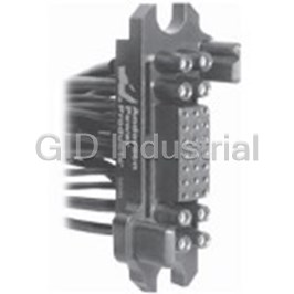
Connector Accessories Power Drawer Pin Housing 8/21 POS 035LDAP
Connector Accessories Power Drawer Socket Housing 8/21 POS 035LDAS
Connector Accessories Power Drawer Pin Housing 4/4/21 POS 035LDBP
Connector Accessories Power Drawer Socket Housing 4/4/21 POS 035LDBS
Connector Accessories Power Drawer Pin Housing 8/21 POS 035LDCP
Connector Accessories Power Drawer Socket Housing 8/21 POS 035LDCS
Request a Quote

The quote request has been received
Close

Facing challenges or have inquiries? Feel free to contact us!
Call Us +1-469-283-2440
What they say about us
FANTASTIC RESOURCE
One of our top priorities is maintaining our business with precision, and we are constantly looking for affiliates that can help us achieve our goal. With the aid of GID Industrial, our obsolete product management has never been more efficient. They have been a great resource to our company, and have quickly become a go-to supplier on our list!
Bucher Emhart Glass
EXCELLENT SERVICE
With our strict fundamentals and high expectations, we were surprised when we came across GID Industrial and their competitive pricing. When we approached them with our issue, they were incredibly confident in being able to provide us with a seamless solution at the best price for us. GID Industrial quickly understood our needs and provided us with excellent service, as well as fully tested product to ensure what we received would be the right fit for our company.
Fuji
HARD TO FIND A BETTER PROVIDER
Our company provides services to aid in the manufacture of technological products, such as semiconductors and flat panel displays, and often searching for distributors of obsolete product we require can waste time and money. Finding GID Industrial proved to be a great asset to our company, with cost effective solutions and superior knowledge on all of their materials, it’d be hard to find a better provider of obsolete or hard to find products.
Applied Materials
CONSISTENTLY DELIVERS QUALITY SOLUTIONS
Over the years, the equipment used in our company becomes discontinued, but they’re still of great use to us and our customers. Once these products are no longer available through the manufacturer, finding a reliable, quick supplier is a necessity, and luckily for us, GID Industrial has provided the most trustworthy, quality solutions to our obsolete component needs.
Nidec Vamco
TERRIFIC RESOURCE
This company has been a terrific help to us (I work for Trican Well Service) in sourcing the Micron Ram Memory we needed for our Siemens computers. Great service! And great pricing! I know when the product is shipping and when it will arrive, all the way through the ordering process.
Trican Well Service
GO TO SOURCE
When I can't find an obsolete part, I first call GID and they'll come up with my parts every time. Great customer service and follow up as well. Scott emails me from time to time to touch base and see if we're having trouble finding something.....which is often with our 25 yr old equipment.
ConAgra Foods