

 Manufacturers
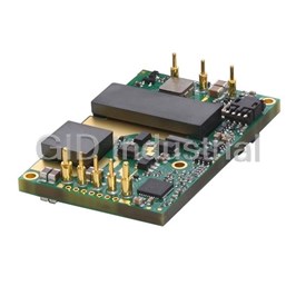
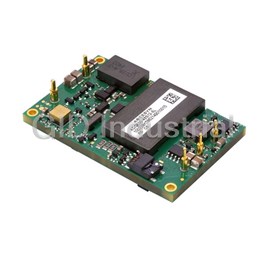
ARTESYN AVQ100-36S3V3B-6L

Description
83 W, 18 -60 VDC Vin, Single Output, 3.3 V@25 A Datacom/Industrial/OEM/Commercial DC-DC Converter in standard 1/4 Brick
Part Number
AVQ100-36S3V3B-6L
Price
Request Quote
Manufacturer
ARTESYN
Lead Time
Request Quote
Category
Capacitors » DC-DC Converter
Specifications
Manufacturer
Artesyn
Manufacturers Part #
AVQ100-36S3V3B-6L
Brand
Artesyn Embedded Technologies
Series
AVQ100-36S3V3
Factory Pack Quantity
1
Application
General Purpose
Connection Type
Through Hole
Dimensions
2.28 x 1.45 x 0.50"
Efficiency
92%
Environmental Conditions
General Purpose
Industry
Datacom, Industrial, OEM/Commercial
Input Type
4:1
Input Voltage Nominal
24, 48
Isolation
1500 VDC
Mechanical Style
Isolated
Mounting
PCB Mount
Number of Outputs
1
Operating Temperature
-40 to +85°C (ambient)
Output Amps 1
25 A
Output Voltage V1 Nominal
3.3 V
Power
83 W
Standard Packaging Size
1/4 Brick
Subcategory
DC-DC Converter
Datasheet

Extracted Text
Technical Reference Note Rev.10.13.14_#1.1 AVQ100-36S3V3 Page 1 AVQ100-36S3V3 82.5 Watts Quarter-brick Converter Total Power: 82.5 Watts Input Voltage: 18 to 60 Vdc # of Outputs: Single Special Features • Delivering up to 25A output • Ultra-high efficiency: 90% (typ., full load,48V).92% (typ.,hald load,24V) Product Descriptions • Wide input range: 18V ~ 60V The AVQ100-36S3V3 is a single output DC/DC converter with standard quarter- • Excellent thermal performance brick outline and pin configuration. It delivers up to 25A output current with 3.3V • No minimum load requirement output voltage. Above 90% ultra-high efficiency and excellent thermal • Start-up and shut-down performance makes it an ideal choice to used in telecom and datacom monotonically into any normal and O applications and can operate under an ambient temperature range of -40 C ~ pre-biased loads, internal pre-bias O +85 C. function circuit prevents back negative current drawn from external load • RoHS5/ 6,RoHS6/6compliant • Remote control function • Remote output sense Applications • Trim function:80%~110% Telecom/ Datacom • Input under voltage lockout • Output over current protection • Output over voltage protection • Over temperature protection • Industry standard quarter-brick pin- out outline • Open frame or baseplate optional • Pin length optional Safety IEC/EN/UL/ 60950-1 CSA-C22.2 CE Mark UL/TUV GB4943 EN55022 Class A T Te ec ch hn niic ca all R Re ef fe er re en nc ce e N No ot te e Rev.10.13.14_#1.1 AVQ100-36S3V3 Model Numbers Page 2 Standard Output Voltage Structure Remote ON/OFF logic RoHS Status AVQ100-36S3V3-6L 3.3Vdc Open frame Negative R6 AVQ100-36S3V3B-6L 3.3Vdc Baseplated Negative R6 Ordering information AVQ100 - 36 S 3V3 P B - 6 L ① ② ③ ④ ⑤ ⑥ ⑦ ⑧ ① Model series AVQ100: high efficiency quarter-brick series ② Input voltage 36: 18V ~ 60V input range, rated input voltage 48V ③ Output number S: single output ④ Rated output voltage 3V3: 3.3V output ⑤ Remote ON/OFF logic Default: negative logic; P: positive logic ⑥ Baseplated B: baseplated; default:open frame ⑦ Pin length 6: 3.8mm ⑧ RoHS status L: RoHS, R6; Y: RoHS, R5 Options None Artesyn Embedded Technologies T Te ec ch hn niic ca all R Re ef fe er re en nc ce e N No ot te e Rev.10.13.14_#1.1 AVQ100-36S3V3 Electrical Specifications Page 3 Absolute Maximum Ratings Stress in excess of those listed in the “Absolute Maximum Ratings” may cause permanent damage to the power supply. These are stress ratings only and functional operation of the unit is not implied at these or any other conditions above those given in the operational sections of this TRN. Exposure to any absolute maximum rated condition for extended periods may adversely affect the power supply’s reliability. Table 1. Absolute Maximum Ratings: Parameter Model Symbol Min Typ Max Unit Input Voltage Operating -Continuous All - - 60 Vdc V IN,DC Non-operating -100mS All - - 80 Vdc Maximum Output Power All P - - 82.5 W O,max 1 Isolation Voltage Input to output Open frame module 1500 - - Vdc Input to baseplate Baseplate module 1500 - - Vdc Output to baseplate Baseplate module 1500 - - Vdc O Ambient Operating Temperature All T -40 - +85 C A O Storage Temperature All T -55 - +125 C STG Voltage at remote ON/OFF pin All -0.7 - 12 Vdc Humidity (non-condensing) Operating All - - 95 % Non-operating - - 95 Note 1 - 1mA for 60s, slew rate of 1500V/10s Artesyn Embedded Technologies T Te ec ch hn niic ca all R Re ef fe er re en nc ce e N No ot te e Rev.10.13.14_#1.1 AVQ100-36S3V3 Input Specifications Page 4 Table 2. Input Specifications: 1 Parameter Conditions Symbol Min Typ Max Unit Operating Input Voltage, DC All V 18 48 60 Vdc IN,DC Turn-on Voltage Threshold I = I V 16.2 16.7 17.2 Vdc O O,max IN,ON Turn-off Voltage Threshold I = I V 14.6 15.1 15.6 Vdc O O, max IN,OFF Lockout Voltage Hysteresis I = I 1.1 1.6 2.1 V O O, max Maximum Input Current V =18V IN,DC I - - 6 A IN,max (I = I ) I = I O O,max O O, max No-load input current I = 0A I - - 0.1 A O IN Standby Input current Remote OFF I - 0.005 0.01 A IN 2 Inrush current transient rating Power ON - - 0.5 A s Fast blow external Recommended Input Fuse - - 15 A fuse recommended Input filter component values (C\L) Internal values - 7.6\2.2 - μF\μH Low ESR capacitor Recommended External Input Capacitance C - 100 - uF IN recommended Through 12uH Input Reflected Ripple Current - 10 20 mA inductor O T =25 C Vin=24V A DC I = I η - 90 - % O O,max I = 50%I - 92 - % O O,max Operating Efficiency O T =25 C Vin=48V A DC I = I η - 90.5 - % O O,max I = 50%I - 90 - % O O,max O Note 1 - Ta = 25 C, airflow rate = 400 LFM, Vin = 48Vdc, nominal Vout unless otherwise noted. Artesyn Embedded Technologies T Te ec ch hn niic ca all R Re ef fe er re en nc ce e N No ot te e Rev.10.13.14_#1.1 AVQ100-36S3V3 Output Specifications Page 5 Table 3. Output Specifications: 1 Parameter Condition Symbol Min Typ Max Unit V = 48V IN,DC DC Factory Set Voltage V 3.267 3.300 3.333 Vdc O I =I O O,max Output Voltage Line Regulation All %V - 0.05 -0.15 % O Output Voltage Load Regulation All %V - 0.05 0.15 % O O Output Voltage Temperature Regulation All %V - 0.02 - %/ C O Total output voltage range All V 3.25 3.30 3.35 V O (Over sample, line, load, temperature & life) Output Voltage Trim Range All V 2.64 - 3.63 V O Output Ripple, pk-pk 20MHz bandwidth V - 40 70 mV O PK-PK Output Current All I 0 - 25 A O 2 Output DC current-limit inception All I 27.5 - 35 A O 3 Reverse current-limit while enabled All 0.5 1.0 2.0 A 4 Reverse current-limit while disabled All 0 10 50 mA Vout pre-bias level All %V - - 90 % O 5 V Load Capacitance All C 470 470 10000 uF O O 50% ~75%~50% ±V - 150 - mV O slew rate = 0.1A/us V Dynamic Response O T - 100 - uSec s Peak Deviation Settling Time 50% ~75%~50% ±V O - 180 - mV slew rate = 1A/us T s - 200 - uSec Rise time I = I T - 10 30 mS O max rise Turn-on delay T turn-on I = I - 5 10 mS O max time Turn-on transient Output voltage I = 0 %V - 0 - % O O overshoot Switching frequency All f 295 300 305 KHz SW O Note 1 - Ta = 25 C, airflow rate = 400 LFM, Vin = 48Vdc, nominal Vout unless otherwise noted. Note 2 - Hiccup: auto-restart when over-current condition is removed. Note 3 - Negative current drawn from output Note 4 - Negative current drawn from output Note 5 - High frequency and low ESR is recommended. Artesyn Embedded Technologies T Te ec ch hn niic ca all R Re ef fe er re en nc ce e N No ot te e Rev.10.13.14_#1.1 AVQ100-36S3V3 Output Specifications Page 6 Table 3. Output Specifications, con’t: 1 Parameter Condition Symbol Min Typ Max Unit Off-state voltage All -0.7 - 1.2 V Remote ON/OFF control (positive logic) On-state voltage All 3.5 - 12 V Off-state voltage All 3.5 - 12 V Remote ON/OFF control (negative logic) On-state voltage All -0.7 - 1.2 V 6 Output over-voltage protection All V 3.8 4.2 5.0 mV O O No baseplate - 118 - C 7 Output over-temperature protection T O Baseplate - 100 - C O Over-temperature hysteresis All T - 5 - C Output voltage remote sense range All ±V - - 0.5 V O Telcordia SR-332- 6 MTBF 2006; 80% load, - 2.5 - 10 h O 300LFM, 40 C Ta Note 6 - Hiccup: auto-restart when over-voltage condition is removed. Note 7 - Auto recovery. Artesyn Embedded Technologies T Te ec ch hn niic ca all R Re ef fe er re en nc ce e N No ot te e Rev.10.13.14_#1.1 AVQ100-36S3V3 AVQ100-36S3V3 Performance Curves Page 7 Figure 1: AVQ100-36S3V3 Input Reflected Ripple Current Waveform Figure2: AVQ100-36S3V3 Ripple and Noise Measurement (2uS/div, 5mA/div) (2uS/div, 20mV/div) Figure 3: AVQ100-36S3V3 Output Voltage Startup Characteristic (5mS/div) Figure 4: AVQ100-36S3V3 Turn Off Characteristic (2mS/div) Ch 1: Vo (1V/div) Ch 2: Vi (20V/div) Ch 1: Vo (1V/div) Ch 2: Vi (20V/div) Figure 5: AVQ100-36S3V3 Remote ON Waveform (5mS/div) Figure 6: AVQ100-36S3V3 Remote OFF Waveform (5mS/div) Ch 1: Vo (1V/div) Ch 2: Remote ON (2V/div) Ch 1: Vo (1V/div) CH 2: Remote OFF (2V/div) Artesyn Embedded Technologies T Te ec ch hn niic ca all R Re ef fe er re en nc ce e N No ot te e Rev.10.13.14_#1.1 AVQ100-36S3V3 AVQ100-36S3V3 Performance Curves Page 8 Figure 8: AVQ100-36S3V3 Transient Response (1mS/div) Figure 7: AVQ100-36S3V3 Transient Response (1mS/div) 50%~75%~50% load change, 1A/uS slew rate 50%~75%~50% load change, 0.1A/uS slew rate Ch 1: Vo (100mV/div) Ch 2: Io (2A/div) Ch 1: Vo (50mV/div) Ch 2: Io (2A/div) 95 90 85 80 75 Vin=24V 70 Vin=48V 65 Vin=60V 60 2.5 5 7.5 10 12.5 15 17.5 20 22.5 25 Output current (A) O Figure 9: AVQ100-36S3V3 Efficiency Curves @ 25 C, Vo=3.3V Artesyn Embedded Technologies Efficiency (%) T Te ec ch hn niic ca all R Re ef fe er re en nc ce e N No ot te e Rev.10.13.14_#1.1 AVQ100-36S3V3 Mechanical Specifications Page 9 Mechanical Outlines – No baseplate Module 57.9 [2.280] 50.83 [2.001] Bottom view 3 4 5 2 6 7 1 8 Side view 6-Φ2.0±0.1 2-Φ1.5±0.1 6-Φ1.0±0.1 Load board Unit: mm[inch] Bottom view: pin on upside Tolerance: X.Xmm±0.5mm[X.X in.±0.02in.] X.XXmm±0.25mm[X.XX in.±0.01in.] Figure 10 Mechanical diagram Artesyn Embedded Technologies 36.8 [1.449] 12.7[0.500]Max. 15.24 [0.600] L 0.3[0.012]Min. 7.62[0.300] 15.24 [0.600] T Te ec ch hn niic ca all R Re ef fe er re en nc ce e N No ot te e Rev.10.13.14_#1.1 AVQ100-36S3V3 Page 10 Mechanical Outlines – Baseplate Module 57.9 [2.280] 50.83 [2.001] BOTTOM VIEW 3 4 5 2 6 7 8 1 SIDE VIEW 6-Ø1.0±0.1 2-Ø1.5±0.1 LOAD BOARD 6-Ø2.0±0.1 TOP VIEW 4-M3 3-M2 47.2 [1.858] 53.5 [2.106] UNIT: mm[inch] BOTTOM VIEW: pin on upside TOLERANCE: X.Xmm±0.5mm[X.X in.±0.02in.] X.XXmm±0.25mm[X.XX in.±0.01in.] Figure 11 Mechanical diagram Artesyn Embedded Technologies 12.7[0.500] 36.8 [1.449] L 15.24 [0.600] 26.2 [1.031] 7.62[0.300] 2.0[0.079] 32.41 [1.276] 0.3[0.012]MIN 15.24 [0.600] 2.8[0.110] T Te ec ch hn niic ca all R Re ef fe er re en nc ce e N No ot te e Rev.10.13.14_#1.1 AVQ100-36S3V3 Pin Length Option Page 11 Device code suffix L -4 4.8mm±0.2 mm -6 3.8mm±0.2 mm -8 2.8mm±0.2 mm None 5.8mm±0.2 mm Pin Designations Pin No Name Function 1 Vin+ Positive input voltage 2 Remote ON/OFF Remote control 3 Vin- Negative input voltage 4 Vo- Negative output voltage 5 S- Negative remote sense 6 Trim Output voltage trim 7 S+ Positive remote sense 8 Vo+ Positive output voltage Artesyn Embedded Technologies T Te ec ch hn niic ca all R Re ef fe er re en nc ce e N No ot te e Rev.10.13.14_#1.1 AVQ100-36S3V3 Environmental Specifications Page 12 EMC Immunity AVQ100-36S3V3 Series power supply is designed to meet the following EMC immunity specifications: Document Description Criteria EN55022, Class A Limits Conducted and Radiated EMI Limits / Electromagnetic Compatibility (EMC) - Testing and measurement IEC/EN 61000-4-2, Level 3 B techniques - Electrostatic discharge immunity test. Enclosure Port Electromagnetic Compatibility (EMC) - Testing and measurement IEC/EN 61000-4-4, Level 3 B techniques, Electrical Fast Transient. DC input port. Electromagnetic Compatibility (EMC) - Testing and measurement IEC/EN 61000-4-5 techniques, Immunity to surges - 600V common mode and 600V B differential mode for DC ports Electromagnetic Compatibility (EMC) - Testing and measurement IEC/EN 61000-4-6, Level 2 A techniques, Continuous Conducted Interference. DC input port Electromagnetic Compatibility (EMC) - Testing and measurement B EN61000-4-29 techniques, Voltage Dips and short interruptions and voltage variations. DC input port Criterion A: Normal performance during and after test. Criterion B: For EFT and surges, low-voltage protection or reset is not allowed. Temporary output voltage fluctuation ceases after disturbances ceases, and from which the EUT recovers its normal performance automatically. For Dips and ESD, output voltage fluctuation or reset is allowed during the test, but recovers to its normal performance automatically after the disturbance ceases. Criterion C: Temporary loss of output, the correction of which requires operator intervention. Criterion D: Loss of output which is not recoverable, owing to damage to hardware. Artesyn Embedded Technologies T Te ec ch hn niic ca all R Re ef fe er re en nc ce e N No ot te e Rev.10.13.14_#1.1 AVQ100-36S3V3 EMC Test Configuration Page 13 : U1 U2 Out+ 1320uH In+ Vo+ Vin+ 22nF/1000V C1 C2 C3 C4 1uF/100V DC/DC Out- In- Vin- Vo- Resistive load PE EMI filter Figure 12 EMC test configuration U1: 5A input EMC filter module U2: Module to test, AVQ100-36S3V3 C1 ~ C4: See Figure 22 Baseplate: Be not connected Artesyn Embedded Technologies T Te ec ch hn niic ca all R Re ef fe er re en nc ce e N No ot te e Rev.10.13.14_#1.1 AVQ100-36S3V3 Safety Certifications Page 14 The AVQ100-36S3V3 Series power supply is intended for inclusion in other equipment and the installer must ensure that it is in compliance with all the requirements of the end application. This product is only for inclusion by professional installers within other equipment and must not be operated as a stand alone product. Table 4. Safety Certifications for AVQ100-36S3V3 series power supply system Document File # Description UL60950-1,CSA-C22.2 US and Canada Requirements EN60950-1, EN55022 European Requirements IEC60950-1 International Requirements GB4943 Chinese Requirements CE CE Marking TVU German Requirements Artesyn Embedded Technologies T Te ec ch hn niic ca all R Re ef fe er re en nc ce e N No ot te e Rev.10.13.14_#1.1 AVQ100-36S3V3 Operating Temperature Page 15 The AVQ100-36S3V3 series power supplies will start and operate within stated specifications at an ambient temperature O O O O from -40 C to 85 C under all load conditions. The storage temperature is -55 C to 125 C. Thermal Considerations ----No baseplate Model The converter is designed to operate in different thermal environments and sufficient cooling must be provided. Proper cooling can be verified by measuring the temperature at the OTP Test Point. The temperature at this point should not exceed the max values in the table5. For a typical application, Figure 15 and Figure 16 show the derating of output current vs. ambient air temperature at different air velocity. OTP Test Point Figure 13 Thermal test points Table 5 Temperature limit of the test points Test point Temperature limit O OTP Test Point 113 C Figure 14 Typical test condition Forced airflow direction is from V - to V + in in Artesyn Embedded Technologies T Te ec ch hn niic ca all R Re ef fe er re en nc ce e N No ot te e Rev.10.13.14_#1.1 AVQ100-36S3V3 Thermal Considerations ---- No Baseplate Model Con’t Page 16 The converter can operate with a smaller heatsink and sufficient airflow. Figure 15 & Figure 16 show the derating output current vs. ambient air temperature at different air velocities with a specified heatsink. . 25 20 15 10 5 0 25 40 55 70 85 Temperature: Ta ( ) ℃℃℃℃ 400LFM(2m/s) 300LFM(1.5m/s) 200LFM(1m/s) 100LFM(0.5m/s) 0LFM(0m/s) Figure 15 Output power derating, 48V , air flowing across the converter from V - to V + in in in 25 20 15 10 5 0 25 40 55 70 85 Temperature: Ta ( ) ℃℃℃℃ 400LFM(2m/s) 300LFM(1.5m/s) 200LFM(1m/s) 100LFM(0.5m/s) 0LFM(0m/s) Figure 16 Output power derating, 24V , air flowing across the converter from V - to V + in in in Artesyn Embedded Technologies Output current Io (A) Output current Io (A) T Te ec ch hn niic ca all R Re ef fe er re en nc ce e N No ot te e Rev.10.13.14_#1.1 AVQ100-36S3V3 Thermal Considerations -- Baseplate Model -- Page 17 The converter is designed to operate in different thermal environments and sufficient cooling must be provided. Proper cooling of the DC/DC converter can be verified by measuring the temperature at the test point(s). The temperature at this/these point(s) should not exceed the max values in the table6. The converter can operate in an enclosed environment without forced air convection. Cooling of the converter is achieved O mainly by conduction from the baseplate to a heatsink. The converter can deliver full output power at 85 C ambient temperature provided the baseplate temperature is kept below the max values in the table6. . Figure 17 Test point on baseplate Table 6 Temperature limit of the test points Test point Temperature limit O OTP Test Point 95 C The converter can also operate with a smaller heatsink and sufficient airflow. Figure20 & Figure21 shows the derating output current vs. ambient air temperature at different air velocity with a specified heatsink. The typical test condition is shown in Figure 18 Figure 18 Typical test condition, Forced airflow direction is from Vin- to Vin+ Artesyn Embedded Technologies T Te ec ch hn niic ca all R Re ef fe er re en nc ce e N No ot te e Rev.10.13.14_#1.1 AVQ100-36S3V3 Thermal Considerations ---- Baseplate Model Con’t Page 18 57.90 4-Φ3.50 4-Φ8.00 26.21±0.1 36.8 47.30±0.1 3.00 12.70 2.00 2.45 3.00 2.45 53.00(2×10+3×11) Figure 19 Outline drawing of the heatsink 25 20 15 10 5 0 25 40 55 70 85 Temperature: Ta ( ) ℃℃℃℃ 400LFM(2m/s) 300LFM(1.5m/s) 200LFM(1m/s) 100LFM(0.5m/s) 0LFM(0m/s) Figure 20 Output power derating, 48V , air flowing across the converter from V - to V + in in in Artesyn Embedded Technologies Output current Io (A) T Te ec ch hn niic ca all R Re ef fe er re en nc ce e N No ot te e Rev.10.13.14_#1.1 AVQ100-36S3V3 Thermal Considerations ---- Baseplate Model Con’t Page 19 25 20 15 10 5 0 25 40 55 70 85 Temperature: Ta ( ) ℃℃℃℃ 400LFM(2m/s) 300LFM(1.5m/s) 200LFM(1m/s) 100LFM(0.5m/s) 0LFM(0m/s) Figure 21 Output power derating,24V , air flowing across the converter from V - to V + in in in Assembly The allowable maximum distance of the screw drove into heat-sink is 3.3mm. Artesyn Embedded Technologies Output current Io (A) T Te ec ch hn niic ca all R Re ef fe er re en nc ce e N No ot te e Rev.10.13.14_#1.1 AVQ100-36S3V3 Qualification Testing Page 20 Parameter Unit (pcs) Test condition O O O Halt test 4-5 T -10 C to T +10 C, 5 C step, V = min to max, 0 ~ 105% load a,min a,max in 2 3 Frequency range: 5Hz ~ 20Hz, 20Hz ~ 200Hz, A.S.D: 1.0m /s , -3db/oct, Vibration 3 axes of vibration: X/Y/Z. Time: 30min/axes Mechanical Shock 3 30g, 6ms, 3axes, 6directions, 3time/direction O O Thermal Shock 3 -40 C to 100 C, unit temperature 20cycles O O O Thermal Cycling 3 -40 C to 55 C, temperature change rate: 1 C/min, cycles: 2cycles O Humidity 3 40 C, 95%RH, 48h Solder Ability 15 IPC J-STD-002C-2007 Artesyn Embedded Technologies T Te ec ch hn niic ca all R Re ef fe er re en nc ce e N No ot te e Rev.10.13.14_#1.1 AVQ100-36S3V3 Application Notes Page 21 Typical Application Below is the typical application of the AVQ100-36S3V3 series power supply. AVQ100 EMI filter Fuse Vo+ Out+ Vin+ In+ S+ C1 C2 C3 C4 CNT Trim Load Vdc S- Vo- Vin- Out- In- Figure 22 Typical application C1: 100μF/100V electrolytic capacitor, P/N: UPW2A101MHD (Nichicon) or equivalent caps C2: 1μF/100V X7R ceramic capacitor, P/N: C3225X7R2A105KT0L0U (TDK) or equivalent caps C3: 1μF/25V X7R ceramic capacitor, P/N: C3225X7R1E105KT000N (TDK) or equivalent caps C4: 470μF electrolytic capacitor, P/N: UUD1H471MNL1GS (Nichicon) or equivalent caps Fuse: External fast blow fuse with a rating of 15A. The recommended fuse model is 0324020 MXP from LITTLEFUSE. . Artesyn Embedded Technologies T Te ec ch hn niic ca all R Re ef fe er re en nc ce e N No ot te e Rev.10.13.14_#1.1 AVQ100-36S3V3 Remote ON/OFF Page 22 Either positive or negative remote ON/OFF logic is available in AVQ100-36S3V3. The logic is CMOS and TTL compatible. Below is the detailed internal circuit and reference in AVQ100-36S3V3. . 10V 12.4k Remote 10V ON/OFF PWM 12.4k controller 15k Remote ON/OFF PWM controller 2.0V 10k 10k Negative logic Positive logic Figure 23 Remote ON/OFF internal diagram Artesyn Embedded Technologies T Te ec ch hn niic ca all R Re ef fe er re en nc ce e N No ot te e Rev.10.13.14_#1.1 AVQ100-36S3V3 Trim Characteristics Page 23 Connecting an external resistor between Trim pin and V - pin will decrease the output voltage. While connecting it between o Trim and V + will increase the output voltage. The following equations determine the external resistance to obtain the o trimmed output voltage. 510 R = −10.2(KΩ) adj−down Δ 5.1×V × (100 + Δ) 510 nom R = − −10.2(KΩ) adj−up 1.225× Δ Δ V −V nom desired Δ = ×100 V nom V : Nominal output voltage. norm For example, to get 3.63V output, the trimming resistor is 5.1× 3.3× (100 +10) 510 R = − −10.2(KΩ) = 89.9KΩ adj−up 1.225×10 10 The output voltage can also be trimmed by potential applied at the Trim pin. V = (V +1.225)× 2.69 O trim Where V is the potential applied at the Trim pin, and V is the desired output voltage. trim O When trimming up, the output current should be decreased accordingly so as not to exceed the maximum output power and the minimum input voltage should be increased as shown in the following figures. Vo+ Vo+ S+ S+ Load Load R trim _down Trim Trim R trim _up Cout Cout S- S- Vo- Vo- Figure 24 Trim up Figure 25 Trim down Artesyn Embedded Technologies T Te ec ch hn niic ca all R Re ef fe er re en nc ce e N No ot te e Rev.10.13.14_#1.1 AVQ100-36S3V3 Input Ripple & Output Ripple & Noise Test Configuration Page 24 Probe Current Probe 50mm L1 Vo+ Vin+ C1 C2 C3 C4 Cin DC/DC Load Vdc Vin- Vo- Figure 26 Input ripple & inrush current, ripple & noise test configuration Vdc: DC power supply L1: 12μH Cin: 220μF/100V typical C1 ~ C4: See Figure 22 Note: Using a coaxial cable with series 50Ω resistor and 0.68μF ceramic capacitor or a ground ring of probe to test output ripple & noise is recommended. Artesyn Embedded Technologies T Te ec ch hn niic ca all R Re ef fe er re en nc ce e N No ot te e Rev.10.13.14_#1.1 AVQ100-36S3V3 Sense Characteristics Page 25 If the load is far from the unit, connect S+ and S- to the terminal of the load respectively to compensate the voltage drop on the transmission line. See Figure 22. If the sense compensate function is not necessary, connect S+ to V + and S- to V - directly. o o . Artesyn Embedded Technologies T Te ec ch hn niic ca all R Re ef fe er re en nc ce e N No ot te e Rev.10.13.14_#1.1 AVQ100-36S3V3 Soldering Page 26 The product is intended for standard manual,reflow or wave soldering. O When reflow soldering is used, the temperature on pins is specified to maximum 260 C for maximum 10s. O When wave soldering is used, the temperature on pins is specified to maximum 260 Cfor maximum 7s. O O When soldering by hand, the iron temperature should be maintained at 300 C~ 380 Cand applied to the converter pins for less than 10s. Longer exposure can cause internal damage to the converter. Cleaning of solder joint can be performed with cleaning solvent IPA or similative. . Artesyn Embedded Technologies T Te ec ch hn niic ca all R Re ef fe er re en nc ce e N No ot te e Rev.10.13.14_#1.1 AVQ100-36S3V3 Hazardous Substances Announcement (RoHS of China R6 ) Page 27 Hazardous Substances Parts 6+ Pb Hg Cd Cr PBB PBDE AVQ100-36S3V3 x x x x x x AVQ100-36S3V3B x x x x x x х: Means the content of the hazardous substances in all the average quality materials of the part is within the limits specified in SJ/T-11363-2006 √: Means the content of the hazardous substances in at least one of the average quality materials of the part is outside the limits specified in SJ/T11363-2006 Artesyn Embedded Technologies has been committed to the design and manufacturing of environment-friendly products. It will reduce and eventually eliminate the hazardous substances in the products through unremitting efforts in research. However, limited by the current technical level, the following parts still contain hazardous substances due to the lack of reliable substitute or mature solution: 1. Solders (including high-temperature solder in parts) contain plumbum. 2. Glass of electric parts contains plumbum. 3. Copper alloy of pins contains plumbum For more information: www.artesyn.com/power For support: productsupport.ep@artesyn.com
Frequently asked questions
How does Electronics Finder differ from its competitors?

Is there a warranty for the AVQ100-36S3V3B-6L?
Which carrier will Electronics Finder use to ship my parts?
Can I buy parts from Electronics Finder if I am outside the USA?
Which payment methods does Electronics Finder accept?
Why buy from GID?

Quality
We are industry veterans who take pride in our work

Protection
Avoid the dangers of risky trading in the gray market

Access
Our network of suppliers is ready and at your disposal

Savings
Maintain legacy systems to prevent costly downtime

Speed
Time is of the essence, and we are respectful of yours
Related Products
500 W, 36 -75 VDC Vin, Single Output, 12 VDC@42 A DC-DC Converter
500 W, 36 -75 VDC Vin, Single Output, 12 VDC@42 A DC-DC Converter
500 W, 36 -75 VDC Vin, Single Output, 12 VDC@42 A DC-DC Converter
500 W, 36 -75 VDC Vin, Single Output, 12 VDC@42 A DC-DC Converter
600 W, 40 -60 VDC Vin, Single Output, 12 VDC@50 A DC-DC Converter
600 W, 40 -60 VDC Vin, Single Output, 12 VDC@50 A DC-DC Converter
Request a Quote

The quote request has been received
Close

Facing challenges or have inquiries? Feel free to contact us!
Call Us +1-469-283-2440
What they say about us
FANTASTIC RESOURCE
One of our top priorities is maintaining our business with precision, and we are constantly looking for affiliates that can help us achieve our goal. With the aid of GID Industrial, our obsolete product management has never been more efficient. They have been a great resource to our company, and have quickly become a go-to supplier on our list!
Bucher Emhart Glass
EXCELLENT SERVICE
With our strict fundamentals and high expectations, we were surprised when we came across GID Industrial and their competitive pricing. When we approached them with our issue, they were incredibly confident in being able to provide us with a seamless solution at the best price for us. GID Industrial quickly understood our needs and provided us with excellent service, as well as fully tested product to ensure what we received would be the right fit for our company.
Fuji
HARD TO FIND A BETTER PROVIDER
Our company provides services to aid in the manufacture of technological products, such as semiconductors and flat panel displays, and often searching for distributors of obsolete product we require can waste time and money. Finding GID Industrial proved to be a great asset to our company, with cost effective solutions and superior knowledge on all of their materials, it’d be hard to find a better provider of obsolete or hard to find products.
Applied Materials
CONSISTENTLY DELIVERS QUALITY SOLUTIONS
Over the years, the equipment used in our company becomes discontinued, but they’re still of great use to us and our customers. Once these products are no longer available through the manufacturer, finding a reliable, quick supplier is a necessity, and luckily for us, GID Industrial has provided the most trustworthy, quality solutions to our obsolete component needs.
Nidec Vamco
TERRIFIC RESOURCE
This company has been a terrific help to us (I work for Trican Well Service) in sourcing the Micron Ram Memory we needed for our Siemens computers. Great service! And great pricing! I know when the product is shipping and when it will arrive, all the way through the ordering process.
Trican Well Service
GO TO SOURCE
When I can't find an obsolete part, I first call GID and they'll come up with my parts every time. Great customer service and follow up as well. Scott emails me from time to time to touch base and see if we're having trouble finding something.....which is often with our 25 yr old equipment.
ConAgra Foods