

 Manufacturers
C&K 51681
Description
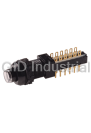
Pushbutton Switches
51681
Part Number
51681
Price
Request Quote
Manufacturer
C&K
Lead Time
Request Quote
Category
Switches » Switch Push Button
Specifications
Manufacturer
C&K
Manufacturers Part #
51681
Industry Aliases
F6UEE
Sub-Category
Push Button Switches
Series
F
Factory Pack Quantity
1
Datasheet

Extracted Text
Pushbutton F Series Pushbutton Switches Features/Benefits Typical Applications A • Up to 10 poles per module • Audio selection • Various contact terminals • Digital equipment interface • Various mounting & switch • Medical equipment interface ganging configurations • Mechanical indicator buttons • RoHS compliant Specifications SWITCHING POWER: F module max. AC/DC: Silver: 50 VA/15W, TYPICAL F OPERATING FORCE: 2U: 6.5N (650 grams); 4U: 6.5N Gold: 1 VA/300 mW. (650 grams); 6U: 7.5N (750 grams); 8U: 9.0N (900 grams); 10U: SWITCHING VOLTAGE: F module max. AC/DC: Silver: 125/30V, 9.0N (900 grams). Gold: 50/30 V. EUROPEAN TYPICAL SF OPERATING FORCE: SWITCHING CURRENT: F module max. AC/DC: Silver: 0.5A/0.5A, 2U: 3.5N±0.5N (350 grams±100 grams); 4U: 5N±1N (500 Gold: 0.04A/0.01A. grams±100 grams); 6U: 6.5N±1N (650 grams±100 grams); 8U: 9.0N±1N (900 grams±100 grams). CARRYING CURRENT: Max at d87u = 20C: Silver: < 2A, Gold: <0.5A. OPERATING TEMPERATURE RANGE: -40˚C to 70˚C. DIELECTRIC STRENGTH (50 Hz, 1 min.): Chassis/contact: ^1500V Between contacts: ^1500V. Materials 5 OPERATING LIFE “OA/EE” (24V/200mA): >10 operations HOUSING: Polycarbonate UL 94V-0 or polyester UL 94V-0. “GR”: >3.5 x 10⁴ operations. ACTUATOR: Polyester UL 94V-0. CONTACT RESISTANCE: Initial: Typical %10 mΩ, max. 20 mΩ MOVABLE CONTACTS: Bimetal brass, silver plated, gold plate After operating life: %100 mΩ over nickel. 9 INSULATION RESISTANCE: ^10 Ω between open contacts, STATIONARY CONTACTS & TERMINALS: Brass, silver plated, 9 ^10 Ω between chassis and contacts. gold plated. CAPACITANCE (at f = 10 kHz): %0.7 pF between 2 contacts. TERMINAL BOARD: Polyester UL 94V-0. TOTAL TRAVEL/LATCHING TRAVEL: 4.7mm/3.3mm (.185 inch/ RETURN SPRING: Music wire. .130 inch). TERMINAL SEAL: RTV adhesive sealant. All models and options are RoHS compliant and compatible. CHASSIS: Steel. NOTE: All models and options are RoHS compliant and compatible. LOCKOUT PIN: Steel. NOTE: Specifications and materials listed above are for switches with standard options. BLOCKERS: Steel. For information on specific and custom switches, consult Customer Service Center. Build-A-Switch To order, simply select desired option from each category and place in the appropriate box. Available options are shown and described on pages A-88 thru A-95. For additional options not shown in catalog, consult Customer Service Center. If requesting only a switch, select either a North American or European switch as noted below. Chassis and buttons are sold separately. If multiple stations are selected, we will assume all switches are the same unless noted otherwise. North American Order Code - Switch Only Designation F F Series Terminal Sealing Contact Material FLT Light touch F series (NONE) None (NONE) Silver, AG ZF Central mounted F series TB Top/bottom AU Gold Contact Arrangement Terminal Style 2U 2PDT (NONE) Solder lugs & PC pins Mechanical Function Dress nut* 4U 4PDT 01A Cut solder lugs OA Momentary *Central mounted F series only 6U 6PDT 01B Cut PC pins, for other configurations, EE Alternate (push-push) 8U 8PDT consult factory GR Interlock (NONE) No dress nut 10U 1OPDT Electrical Function AOR Central release B Black (NONE) BBM Break-Before-Make OASP Momentary with lockout C Chrome M MBB (special) Make-Before-Break GRSP Interlock with lockout Dimensions are shown: Inches (mm) Specifications and dimensions subject to change www.ckswitches.com A-87 F Series Pushbutton Switches A European Order Code - Switch Only Designation Terminal Style Contact Material SF F Series (NONE) Solder lugs & (NONE) Silver, AG ZF Central mounted F series PC pins P Gold Contact Arrangement LB Cut solder lugs Dress nut* 2U 2PDT PB Cut PC pins, for other Mechanical Function *Central mounted F series only 4U 4PDT configurations, OA Momentary 6U 6PDT consult factory EE Alternate (push-push) (NONE) No dress nut 8U 8PDT GR Interlock Electrical Function B Black (NONE) BBM C Chrome *Minimum order quantities apply. Order Code - Buttons Solid Buttons Mechanical Indicator Buttons Style Style Button Color F01 FMR Shell Color F01 FA100 01 Black F02 FG* F02 FA101 01 Black 02 White F12 FSC F07 FA120 03 Red Out Position Color F13 FSD F08 FA2O1 04 Light gray 01 Black F14 FU12 F11 FA200* F15 FSB F16 FE In Position Color F19 FA 02 White F21 F001 06 Yellow 07 Blue 08 Green *Button options for central mounting configurations, 12 Orange use ‘FG’ for central mount with chrome dress nut, use ‘FA200’ for central mount with black dress nut. BUTTON REMOVAL A button of a push-push switch should only be removed in the “OFF” non-latching position. Order Code - Chassis To order a switch with chassis, create the switch part number listed above and add the Chassis part number configurator information at the end of the part number. Note: We do not guarantee or recommend interlocking beyond 10 stations. C No. of Stations Special Acknowledgements 01 thru 23 Comes with standard See note Spacing between Stations .094 (2,4mm) mounting holes 00 Single station Note: Single station chassis 10 10mm available with special mounting 12.5 12.5mm configurations, consult factory. 15 15mm 17.5 17.5mm *Minimum order quantities apply. 20 20mm Dimensions are shown: Inches (mm) Specifications and dimensions subject to change www.ckswitches.com A-88 Pushbutton Pushbutton F Series Pushbutton Switches SWITCHES WITH STANDARD OPTIONS A F2UEE CONTACT LENGTH ARRANGEMENT DIM ‘L’ 2U 0.827 (21,00) 4U 1.300 (33,00) 6U 1.770 (45,00) 8U 2.240 (57,00) 10U 2.720 (69,00) ZF2UEEBF11010108 CONTACT LENGTH ARRANGEMENT DIM ‘L’ 2U 0.827 (21,00) 4U 1.300 (33,00) 6U 1.770 (45,00) 8U 2.240 (57,00) 10U 2.720 (69,00) DESIGNATION Designation, North America Designation, Europe F F Series SF F Series FLT Light touch F series ZF Central mounted F series ZF Central mounted F series Third Angle Projection Dimensions are shown: Inches (mm) Specifications and dimensions subject to change www.ckswitches.com A-89 F Series Pushbutton Switches CONTACT ARRANGEMENT A PC MOUNTING OPTION CODE NO. OF POLES SCHEMATIC 2U 2PDT 4U 4PDT 2X 6U 6PDT 3X 8U 8PDT 4X 10U 10PDT 5X MECHANICAL FUNCTION North America Europe OPTION CODE FUNCTION OPTION CODE FUNCTION OA Momentary OA Momentary EE Alternate (push-push) EE Alternate (push-push) GR Interlock GR Interlock AOR Central release OASP Momentary with lockout GRSP Interlock with lockout TERMINAL SEALING (NONE) NO SEAL TB TOP & BOTTOM F2UEE shown in example above. NOTE: Available for North America only Third Angle Projection Dimensions are shown: Inches (mm) Specifications and dimensions subject to change www.ckswitches.com A-90 Pushbutton Pushbutton F Series Pushbutton Switches TERMINAL STYLE A (NONE) SOLDER LUGS & PC PINS 01A CUT SOLDER LUGS (North America) 01B CUT PC PINS (North America) LB CUT SOLDER LUGS (Europe) PB CUT PC PINS (Europe) .067 (1.70) .079 (2.01) ELECTRICAL FUNCTION OPTION CODE FUNCTION (NONE) BBM Non-shorting M MBB Shorting (North America only) CONTACT MATERIAL EUROPE RoHS NORTH AMERICA RoHS OPTION CODE COMPLIANT * OPTION CODE COMPATIBLE * MATERIAL RATING (NONE) (NONE) YES YES SILVER, AG 50 VA/15 W; 125/30 V; 0.5/0.5 A 1 VA/300mW; 50/30 V; 0.04 A/0.01 A AU P YES YES GOLD * Note: See Technical Data section of this catalog for RoHS compliant and compatible definitions and specifications. DRESS NUT (NONE) NO DRESS NUT FOR F & F/LT B BLACK C CHROME DESIGNATIONS PANEL CUTOUT PANEL CUTOUT NOTE: Available with ZF designation and FG button. NOTE: Available with ZF designation and FA200 buttons. Third Angle Projection Dimensions are shown: Inches (mm) Specifications and dimensions subject to change www.ckswitches.com A-91 F Series Pushbutton Switches COLOR SOLID BUTTON STYLE A STYLE F01 FMR F02 FG F12 FSC F15 FSB F13 FSD F14 FU12 F19 FA F21 F001 F16 FE OPTION CODE COLOR 01 BLACK 02 WHITE 03 RED 04 LT. GRAY Dimensions are shown: Inches (mm) Specifications and dimensions subject to change www.ckswitches.com A-92 Pushbutton Pushbutton F Series Pushbutton Switches SHELL COLOR IN POSITION COLOR MECHANICAL BUTTON STYLE OUT POSITION COLOR A STYLE F02 FA101 F01 FA100 F07 FA120 F08 FA201 F11 FA200 SHELL COLOR 01 BLACK OUT POSITION COLOR 01 BLACK IN POSITION COLOR OPTION CODE COLOR 02 WHITE 06 YELLOW 07 BLUE 08 GREEN 12 ORANGE Dimensions are shown: Inches (mm) Specifications and dimensions subject to change www.ckswitches.com A-93 F Series Pushbutton Switches SPACING CHASSIS NO. OF STATIONS A NUMBER OF STATIONS C00 Thru C10 Comes with standard 0.094 (2,44mm) mounting holes NOTE: Single station chassis available with mounting configurations, consult factory. SPACING 00 SINGLE STATION 10 10mm No. of Stations Dim. ‘A’ Dim. ‘B’ Tolerance 1.182 1.418 2 0.005 (30,02) (36,02) 1.575 1.811 3 0.010 (40,01) (46,00) 1.969 2.205 4 0.010 (50,01) (56,01) .394 2.363 2.599 5 0.010 (10,0) (60,02) (66,01) 2.757 2.993 6 0.015 (70,03) (76,02) 3.150 3.386 7 0.015 (80,01) (86,00) 3.544 3.780 8 0.015 (90,02) (96,01) 3.938 4.174 9 0.015 (100,03) (106,02) 4.331 4.567 10 0.015 (110,01) (116,00) 12.5 12.5mm No. of Stations Dim. ‘A’ Dim. ‘B’ Tolerance 1.200 1.436 2 0.005 (30,48) (36,47) 1.692 1.928 3 0.010 (42,98) (48,97) 2.184 2.420 4 0.010 (55,47) (61,47) .492 2.676 2.912 (12,5) 5 0.010 (67,97) (73,96) 3.169 3.405 6 0.015 (80,49) (86,49) 3.661 3.897 7 0.015 (92,99) (98,98) 4.153 4.389 8 0.015 (105,49) (111,48) 4.645 4.881 9 0.015 (117,98) (123,98) 5.137 5.373 10 0.015 (130,48) (136,47) Third Angle Projection Dimensions are shown: Inches (mm) Specifications and dimensions subject to change www.ckswitches.com A-94 Pushbutton Pushbutton F Series Pushbutton Switches SPACING CHASSIS NO. OF STATIONS A SPACING 15 15mm No. of Stations Dim. ‘A’ Dim. ‘B’ Tolerance 1.374 1.615 2 0.005 (34,90) (41,02) 1.969 2.205 3 0.010 (50,01) (56,01) 2.560 2.796 .591 4 0.010 (65,02) (71,02) (15,0) 3.150 3.386 5 0.010 (80,01) (86,00) 3.741 3.977 6 0.015 (95,02) (101,02) 4.332 4.568 7 0.015 (110,03) (116,03) 4.922 5.158 8 0.015 (125,02) (131,01) 5.513 5.749 9 0.015 (140,03) (146,02) 6.103 6.339 10 0.015 (155,02) (161,01) 17.5 17.5mm No. of Stations Dim. ‘A’ Dim. ‘B’ Tolerance 1.477 1.713 2 0.005 (37,52) (43,51) 2.166 2.402 3 0.010 (55,02) (61,01) 2.855 3.091 4 0.010 (75,52) (78.51) 3.544 3.780 5 0.010 (90,02) (96,01) 4.233 4.469 6 0.015 (107,52) (113,51) 4.922 5.158 7 0.015 (125,02) (131,01) 5.611 5.847 8 0.015 (142,52) (148.51) 6.300 6.536 9 0.015 (160,02) (166,01) 6.989 7.225 10 0.015 (177,52) (183,52) 20 20mm No. of Stations Dim. ‘A’ Dim. ‘B’ Tolerance 1.575 1.811 2 0.005 (40,01) (46,00) 2.363 2.599 3 0.010 (60,02) (66,01) 3.150 3.386 4 0.010 (80,01) (86,00) 3.938 4.174 5 0.010 (100,03) (106,02) 4.725 4.961 6 0.015 (120,02) (126,01) 5.512 5.748 7 0.015 (140,00) (146,00) 6.300 6.536 8 0.015 (160,02) (166,01) 7.087 7.323 9 0.015 (180,01) (186,00) 7.875 8.111 10 0.015 (200,03) (206,02) Third Angle Projection Dimensions are shown: Inches (mm) Specifications and dimensions subject to change www.ckswitches.com A-95
Frequently asked questions
How does Electronics Finder differ from its competitors?

Is there a warranty for the 51681?
Which carrier will Electronics Finder use to ship my parts?
Can I buy parts from Electronics Finder if I am outside the USA?
Which payment methods does Electronics Finder accept?
Why buy from GID?

Quality
We are industry veterans who take pride in our work

Protection
Avoid the dangers of risky trading in the gray market

Access
Our network of suppliers is ready and at your disposal

Savings
Maintain legacy systems to prevent costly downtime

Speed
Time is of the essence, and we are respectful of yours
Related Products
Request a Quote

The quote request has been received
Close

Facing challenges or have inquiries? Feel free to contact us!
Call Us +1-469-283-2440
What they say about us
FANTASTIC RESOURCE
One of our top priorities is maintaining our business with precision, and we are constantly looking for affiliates that can help us achieve our goal. With the aid of GID Industrial, our obsolete product management has never been more efficient. They have been a great resource to our company, and have quickly become a go-to supplier on our list!
Bucher Emhart Glass
EXCELLENT SERVICE
With our strict fundamentals and high expectations, we were surprised when we came across GID Industrial and their competitive pricing. When we approached them with our issue, they were incredibly confident in being able to provide us with a seamless solution at the best price for us. GID Industrial quickly understood our needs and provided us with excellent service, as well as fully tested product to ensure what we received would be the right fit for our company.
Fuji
HARD TO FIND A BETTER PROVIDER
Our company provides services to aid in the manufacture of technological products, such as semiconductors and flat panel displays, and often searching for distributors of obsolete product we require can waste time and money. Finding GID Industrial proved to be a great asset to our company, with cost effective solutions and superior knowledge on all of their materials, it’d be hard to find a better provider of obsolete or hard to find products.
Applied Materials
CONSISTENTLY DELIVERS QUALITY SOLUTIONS
Over the years, the equipment used in our company becomes discontinued, but they’re still of great use to us and our customers. Once these products are no longer available through the manufacturer, finding a reliable, quick supplier is a necessity, and luckily for us, GID Industrial has provided the most trustworthy, quality solutions to our obsolete component needs.
Nidec Vamco
TERRIFIC RESOURCE
This company has been a terrific help to us (I work for Trican Well Service) in sourcing the Micron Ram Memory we needed for our Siemens computers. Great service! And great pricing! I know when the product is shipping and when it will arrive, all the way through the ordering process.
Trican Well Service
GO TO SOURCE
When I can't find an obsolete part, I first call GID and they'll come up with my parts every time. Great customer service and follow up as well. Scott emails me from time to time to touch base and see if we're having trouble finding something.....which is often with our 25 yr old equipment.
ConAgra Foods