

 Manufacturers
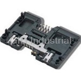
C&K CCM033002 LFT
Description
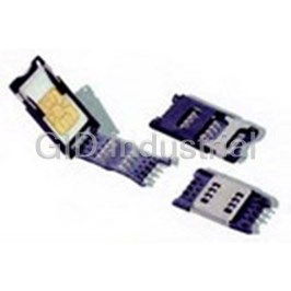
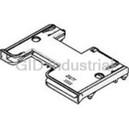
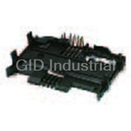
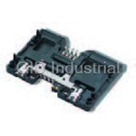
Conn SIM/SAM SKT 6 POS 2.54mm Solder ST SMD Automotive 1A Reel
CCM033002 LFT
Part Number
CCM033002 LFT
Price
Request Quote
Manufacturer
C&K
Lead Time
Request Quote
Category
Connectors » Connector Memory Card
Specifications
Manufacturer
C&K
Manufacturers Part #
CCM033002 LFT
Lead Time
11 Week Lead Time
Industry Aliases
CCM03-3002LFT
Sub-Category
Memory Card Connectors
Packaging
Reel
Factory Pack Quantity
5000
Datasheet

Extracted Text
CCM03 MK2 Series Features Typical Applications • Handheld products • SIM/SAM card acceptance • Identification • Hinged and fixed covers • POS • Compatible with pick and place and lead free soldering • Automotive Mechanical Switch Electrical Data Card detection switch Normally open Number of Contacts 6 or 8 Mechanical life, hinged cover 10,000 cycles min Contact resistance 100 mΩ max Dielectric strength 250 Vrms min Mechanical life, fixed cover 50,000 cycles Card insertion force Hinged cover: 1N max Current rating 1 mA min / 10m A max Maximum power 0.2 VA Fixed cover: 3N max Card extraction force Hinged cover: 1N max Fixed cover: 0,80N min / 3N max Contact force 0,25N min / 0,50N max Environment Data Slide locking force 2N min / 6N max 1,8N max. for complete depression Operating temperature -40°C to +85°C 2 Damp heat IEC 512 test number 11c (10 days) Vibration Frequency 10 to 500 Hz. Acceleration 50m/s Duration 6 hours - amplitude 0,35 mm Salt mist IEC 512 test number 11f (96 hours) RoHS compliant Max electrical discontinuity 1μs 2 Shock Peak value 500 m/s – Duration 11 ms 3 shocks in each direction of each axis Soldering Process Compatible with lead free SMT soldering process Contact Electrical Data Insulation resistance 1,000 MΩ min Resistance 100 mΩmax Current rating 10 μA min / 1 A max Dielectric strength 750 Vrms min Card Total Contact # of PCB Operating Designation Cover Presence Height Dim. (mm) Packaging Plating Contacts Version Life (mm) Switch CCM03-3001LFT inlay hinged 6 without 10,000 2,55 17,2 x 29,65 reels of 1,000 pcs CCM03-3002LFT inlay hinged 6 2 plastic pegs without 10,000 2,55 17,2 x 29,65 reels of 1,000 pcs CCM03-3003LFT inlay hinged 8 without 10,000 2,55 17,2 x 29,65 reels of 1,000 pcs CCM03-3004LFT inlay hinged 8 2 plastic pegs without 10,000 2,55 17,2 x 29,65 reels of 1,000 pcs CCM03-3009LFT gold hinged 6 without 10,000 2,55 17,2 x 29,65 reels of 1,000 pcs CCM03-3010LFT gold hinged 6 2 plastic pegs without 10,000 2,55 17,2 x 29,65 reels of 1,000 pcs CCM03-3011LFT gold hinged 8 without 10,000 2,55 17,2 x 29,65 reels of 1,000 pcs CCM03-3012LFT gold hinged 8 2 plastic pegs without 10,000 2,55 17,2 x 29,65 reels of 1,000 pcs CCM03-3013LFT gold hinged 6 with 10,000 2,55 17,2 x 29,65 reels of 1,000 pcs CCM03-3512LFT gold hinged 6 Large soldering pads* without 10,000 2,55 17,2 x 29,65 reels of 1,000 pcs CCM03-3504LFT gold fixed 8 without 50,000 2,85 17,2 x 25,5 reels of 1,000 pcs CCM03-3505LFT gold fixed 6 without 50,000 2,85 17,2 x 25,5 reels of 1,000 pcs CCM03-3754LFT inlay fixed 6 with 10,000 3,5 16,5 x 18,05 reels of 1,000 pcs CCM03-3760LFT inlay fixed 6 without 10,000 3,45 16,5 x 15,85 reels of 1,000 pcs CCM03-3764LFT inlay none 6 with 10,000 2,9 16,5 x 15,85 reels of 1,000 pcs * Can go through reţ ow upside down 24 SIM/SAM 0,4 CCM03 MK2 Series CCM03-3001 LFT / CCM03-3009 LFT 25,5±0,2 0,4 2,1 13,15 MICROSIM CARD 180?max Mated condition 0,7 3,813,81 25˚ SEE DETAIL A (25,5) (29,65) DETAIL A 29,65 Scale 5 5,65±0,2 13,8 2 3,5 2,45 R 1,9 1,25 0,8 Slider locked (25,5) Bump Pick and place area ø 3,5 XX-XXX Date Code area 3,81 3,8 R 1,9 RECOMMENDED PC BOARD LAYOUT (Component side) Plastic outline Contact foot area 1,5 23,2 1,5 0,8 x 1 5,5 2,5 5,5 1,55 Pad C5 C1 C6 C2 C7 C3 3,813,81 9,34 Prohibited area 25,5 Contact location according to ENV1375-1 & GSM11-11 Dimensions are shown in mm Specifications and dimensions subject to change www.ck-components.com 29 25,4±0,2 (25) 28,4 2,55 (2,7 max. includes solder tails) 1,27 8,6 3,7 9,65 2x 2,54 1,8 6x 11,25 1,25 1,3 1 0,3 A 17,2 2x 2,54 6x 1,3 1,27 0,2 0,65 8,6 A 0 0,1 -0,1 (17,2) (15) SIM/SAM 0,4 CCM03 MK2 Series CCM03-3002 LFT / CCM03-3010 LFT 25,5±0,2 0,4 B 2,1 13,15 MICROSIM CARD 180˚max 10,16 20,32 Mated condition 3,813,81 0,7 25˚ 2x ø1±0,05 ø 0,1 A B SEE DETAIL A (29,65) (25,5) DETAIL A 29,65 Scale 5 5,65±0,2 13,8 2 3,5 2,45 R 1,9 1,25 0,8 Slider locked (25,5) Bump Pick and place area ø 3,5 XX-XXX Date Code area 3,81 3,8 R 1,9 RECOMMENDED PC BOARD LAYOUT (Component side) 1,5 23,2 1,5 20,32 1,44 Plastic outline +0,1 2x Contact foot area ø 1,2 0 ø 0,1 0,8 x 1 5,5 2,5 5,5 Pad C5 C1 C6 C2 C7 C3 3,813,81 6,35 Prohibited area 9,34 Contact location according to 25,5 ENV1375-1 &GSM11-11 Dimensions are shown in mm Specifications and dimensions subject to change www.ck-components.com 30 25,4±0,2 (25) 28,4 SIM/SAM 2,55 (2,7 max. includes solder tails) 10,16 10,16 5,08 5,08 1,27 8,6 3,7 9,65 2x 2,54 1,8 6x 11,25 1,25 1,3 1 0,3 A 2x 2,54 17,2 6x 1,3 0,7 1,27 0,2 8,6 0,65 A 0 0,1 -0,1 (17,2) (15) 0,4 CCM03 MK2 Series CCM03-3003 LFT 25,5±0,2 0,4 2,1 13,15 MICROSIM CARD 180?max Mated condition 0,7 3,813,81 25˚ SEE DETAIL A (25,5) (29,65) DETAIL A 29,65 Scale 5 5,65±0,2 13,8 2 3,5 2,45 1,25 R 1,9 0,8 Slider locked (25,5) Bump Pick and place area ø 3,5 XX-XXX Date Code area 3,81 3,8 R 1,9 RECOMMENDED PC BOARD LAYOUT (Component side) Plastic outline Contact foot area 1,5 23,2 1,5 0,8 x 1 5,5 2,5 5,5 1,55 Pad C5 C1 C6 C2 C7 C3 C8 C4 3,813,81 9,34 25,5 Prohibited area Contact location according to ENV1375-1 & GSM11-11 Dimensions are shown in mm Specifications and dimensions subject to change www.ck-components.com 31 25,4±0,2 (25) 28,4 2,55 (2,7 max. includes solder tails) 1,27 8,6 3,7 9,65 3x 2,54 1,8 8x 11,25 1,25 1,3 1 0,3 A 3x 2,54 17,2 8x 1,3 1,27 0,2 8,6 0,65 A 0 0,1 -0,1 (17,2) (15) SIM/SAM 0,4 CCM03 MK2 Series CCM03-3004 LFT 25,5±0,2 0,4 B 2,1 13,15 MICROSIM CARD 180˚max 10,16 20,32 Mated condition 3,813,81 0,7 25˚ 2x ø1±0,05 (29,65) SEE DETAIL A ø 0,1 A B (25,5) DETAIL A 29,65 Scale 5 5,65±0,2 13,8 2 3,5 2,45 R 1,9 1,25 0,8 Slider locked (25,5) Bump Pick and place area ø3,5 XX-XXX Date Code area 3,81 3,8 R 1,9 RECOMMENDED PC BOARD LAYOUT (Component side) 1,5 23,2 1,5 20,32 1,44 Plastic outline +0,12x Contact foot area 1,2 ø 0 ø 0,1 0,8 x 1 5,5 2,5 5,5 Pad C5 C1 C6 C2 C7 C3 C8 C4 3,813,81 6,35 Prohibited area 9,34 Contact location according to 25,5 ENV1375-1 &GSM11-11 Dimensions are shown in mm Specifications and dimensions subject to change www.ck-components.com 28 25,4±0,2 (25) 28,4 SIM/SAM 2,55 (2,7 max. includes solder tails) 10,16 10,16 5,08 5,08 1,27 3,7 9,65 8,6 3x 2,54 1,8 8x 11,25 1,25 1,3 1 0,3 A 3x 2,54 17,2 0,7 8x 1,27 1,3 8,6 0,2 0,65 A 0 0,1 -0,1 (17,2) (15) 0,4 CCM03 MK2 Series CCM03-3011 LFT 25,5±0,2 0,4 2,1 13,15 MICROSIM CARD 180˚ max Mated condition 0,7 3,813,81 25˚ (29,65) SEE DETAIL A (25,5) DETAIL A 29,65 Scale 5 5,65±0,2 13,8 2 3,5 2,45 R 1,9 1,25 0,8 Slider locked (25,5) Bump Pick and place area ø 3,5 XX-XXX Date Code area 3,81 3,8 R 1,9 RECOMMENDED PC BOARD LAYOUT (Component side) Plastic outline Contact foot area 1,5 23,2 1,5 0,8 x 1 2,5 5,5 5,5 1,55 Pad C5 C1 C6 C2 C7 C3 C8 C4 3,813,81 9,34 25,5 Prohibited area Contact location according to ENV1375-1 & GSM11-11 Dimensions are shown in mm Specifications and dimensions subject to change www.ck-components.com 29 25,4±0,2 (25) 28,4 2,55 (2,7 max. includes solder tails) 3,7 9,65 1,27 8,6 3x 2,54 8x 1 11,25 1,25 1,3 0,3 A 1,8 3x 2,54 17,2 1,27 0,65 8x 1,3 0,2 A 0 0,1 -0,1 (15) (17,2) SIM/SAM 0,4 CCM03 MK2 Series CCM03-3012 LFT 25,5±0,2 0,4 B 2,1 13,15 MICROSIM CARD 180˚max 10,16 20,32 Mated condition 3,813,81 0,7 25˚ 2x (29,65) ø1±0,05 SEE DETAIL A ø 0,1A B (25,5) DETAIL A 29,65 Scale 5 5,65±0,2 13,8 2 3,5 2,45 R 1,9 1,25 0,8 Slider locked (25,5) Bump Pick and place area ø 3,5 XX-XXX Date Code area 3,81 3,8 R 1,9 RECOMMENDED PC BOARD LAYOUT (Component side) 1,5 23,2 1,5 20,32 1,44 Plastic outline +0,12x 1,2 Contact foot area ø 0 ø0,1 0,8 x 1 5,5 2,5 5,5 Pad C5 C1 C6 C2 C7 C3 C8 C4 3,813,81 6,35 Prohibited area 9,34 Contact location according to 25,5 ENV1375-1 &GSM11-11 Dimensions are shown in mm Specifications and dimensions subject to change www.ck-components.com 30 25,4±0,2 (25) 28,4 SIM/SAM 2,55 (2,7 max. includes solder tails) 10,16 10,16 5,08 5,08 3,7 9,65 1,27 8,6 3x 2,54 8x 1,8 11,25 1,25 1,3 1 0,3 A 3x 2,54 17,2 0,7 1,27 8x 8,6 0,65 1,3 0,2 A 0 0,1 -0,1 (17,2) (15) 0,4 CCM03 MK2 Series CCM03-3013 LFT 25,5±0,2 0,4 2,1 13,15 MICROSIM CARD 180˚max Mated condition 0,7 3,81 3,81 25˚ SEE DETAIL A (25,5) DETAIL DETAIL A insulated blade switch 29,65 Scale 5 Scale 5 5,65±0,2 13,8 2 3,5 2,45 1,25 R 1,9 0,8 Plastic actuator Slider locked (25,5) XX-XXX Pick and place area ø 3,5 Date Code area 3,81 3,8 R 1,9 RECOMMENDED PC BOARD LAYOUT (Component side) Plastic outline Contact foot area 1,5 23,2 1,5 0,8 x 1 2,5 5,5 5,5 1,55 Pad C5 C1 C6 C2 C7 C3 (29,65) SW SW 3,813,81 9,34 25,5 Prohibited area Contact location according to ENV1375-1 & GSM11-11 Dimensions are shown in mm Specifications and dimensions subject to change www.ck-components.com 31 25,4±0,2 (25) 28,4 2,55 (2,7 max. includes solder tails) 3,7 9,65 1,27 8,6 3x 2,54 8x 1,25 1,3 1 1,8 11,25 0,3 A 3x 2,54 17,2 0,65 1,27 8,6 8x 1,3 0,2 A 0 0,1 -0,1 (17,2) (15) SIM/SAM 0,4 CCM03 MK2 Series CCM03-3512 LFT 26,9±0,2 2,1 13,15 (0,3) MICROSIM CARD 180˚max Mated condition 0,7 3,81 3,81 25˚0' (29,65) (26,9) SEE DETAIL A DETAIL A (29,95) Scale 5 29,65 5,65±0,2 13,8 2 3,5 2,45 1,25 R 1,9 1,5 Slider locked (26,9) Bump Pick and place area ø 3,5 XX-XXX Date Code area 3,81 3,8 R 1,9 RECOMMENDED PC BOARD LAYOUT (Component side) Plastic outline 1,95 23,5 1,95 Contact foot area 1,4 1,5 x 1 5,5 2,5 5,5 Pad C5 C1 C6 C2 C7 C3 3,81 3,81 9,34 Prohibited area 26,9 Contact location according to ENV1375-1 & GSM11-11 Dimensions are shown in mm Specifications and dimensions subject to change www.ck-components.com 36 , 25 4±0,2 (25) 28,4 SIM/SAM 2,55 (2,7 max. includes solder tails) 3,7 9,65 1,27 8,6 2x 2,54 6x 11,25 1,25 1,3 1 0,3 A 1,8 17,2 2x 2,54 1,27 7,33±0,05 0,65 6x A 1,3 0,05 0,85 0 0,1 -0,1 (17,2) (15) CCM03 MK2 Series CCM03-3504 LFT / CCM03-3505 LFT 25,5±0,2 12,75 2,5 DETAIL A Scale 5 10,16 Mated condition 40˚ SEE DETAIL A 3,81 3,81 2 0,8 2,65 (25,5) 12,1 30˚ 25,5 B 0,15 min Pick and place area Card stop ø 3,5 +0,05 1,4 ø 0 A A XX-XXX ø1,6 0,75 2,3 Date Code area B +0,05 1,4 12,9 0 21,55 RECOMMENDED PC BOARD LAYOUT (Component side) 1,5 23,2 1,5 Plastic outline +0,05 1,4 ø 0 Contact foot area 1,44 2x 0,8 x 1 5,5 2,5 5,5 Pad C5 C1 C6 C2 C7 C3 C8 C4 (3,45) (25,5) (9,75) 3,81 3,81 6,35 Prohibited area Contact location according to ENV1375-1 & GSM11-11 25,5 Dimensions are shown in mm Specifications and dimensions subject to change www.ck-components.com 33 2,85 (3 max includes solder tails) A 1,27 17,2±0,05 8,6 1,27 8,6 +0,1 15,2 0 3x 2,54 3x 2,54 8x 0,8 1 0,3 A 0,4 1,8 1,9 1,25±0,05 2,54 2,45 0,4 12,7 8x 1,3 0,2 2,54 12,7 0,3±0,02 0 0,1 -0,1 0,2 (17,2) SIM/SAM R1 CCM03 MK2 Series CCM03-3754 LFT DETAIL A A-A Mated condition Date code updated SEE DETAIL A 3,81 3,81 F 6 2 2 (9,9) (15,85) 0,8 0,8 14,25±0,2 3,8±0,2 (14,25) (3,8) 11,8 +0,05 +0,10 5,9 1,9 0,85 0 -0,15 2,4 2,4 Pick and place area ø 3,5 Card stop 0,9±0,25 7 0,95±0,2 A A XXXX 3,05 3,05 4,9 9,2 3,5 Date Code area +0,10 0,75 15,1 -0,05 RECOMMENDED PC BOARD LAYOUT (Component side) Plastic outline Contact foot area 1,5 1,5 11,95 3,8 1,5 0,8 x 0,7 1,5 Pad 0,075 C5 C1 C6 C2 C7 C3 SW SW Switch contact foot area 3,81 3,81 2,165 0,8 x 1 5,9 Contact location according to ENV1375-1 & GSM11-11 14,25 3,8 Dimensions are shown in mm Specifications and dimensions subject to change www.ck-components.com 40 SIM/SAM 16,5 2,5 11,1 0,25± 0,05 x 45˚ 6x 2,54 2,54 2,54 2,54 0,7 0,2±0,05 0,3 A 1,27 0,4 8,15 2x 1 0,3 A 0 6,05 0,1 -0,1 A 8x 8,15 1,3 0,2 2,54 2,54 2,54 2,54 (2) (4,34) (4,34) 1,27 1,27 15,3 0,6 (16,5) R1 CCM03 MK2 Series CCM03-3760 LFT COUPE A-A DETAIL A SEE DETAIL A Mated condition 3,81 3,81 2 (9,9) (15,85) 0,8 (14,25) 14,25±0,2 11,8 5,9 +0,05 1,9 0,75 0 2,4 2,4 Pick and place area ø 3,5 Card stop A A XXXX 3,05 4,9 9,2 Date Code area +0,10 0,75 15,1 -0,05 RECOMMENDED PC BOARD LAYOUT (Component side) Plastic outline Contact foot area 1,5 11,95 1,5 0,8 x 0,7 Pad 0,075 C5 C1 C6 C2 C7 C3 3,81 3,81 2,165 5,9 Contact location according to ENV1375-1 & GSM11-11 14,25 Dimensions are shown in mm Specifications and dimensions subject to change www.ck-components.com 41 16,5 11,1 0,25 ± 0,05 x 45˚ 2,5 6x 0,7 0,2±0,05 0,3 A 2,54 2,54 0,4 1,27 8,15 6,05 0 0,1 -0,1 6x 1,3 0,2 A 8,15 2,54 2,54 (7,08) (4,34) 1,27 1,27 15,3 0,6 (16,5) SIM/SAM CCM03 MK2 Series CCM03-3764 LFT Mated condition SEE DETAIL A 3,81 3,81 6 F 2 2 0,8 0,8 (9,9) (15,85) (14,25) (3,8) 14,25±0,2 3,8±0,2 11,8 5,9 +0,05 1,9 0,75 0 Pick and place area ø 3,5 +0,1 0,95 0 Card stop 0,9 ±0,25 7 0,95±0,2 A A XXXX 4,9 9,2 2,9 Date Code area +0,10 0,75 15,1 -0,05 RECOMMENDED PC BOARD LAYOUT Plastic outline (Component side) Contact foot area 0,8 x 0,7 1,5 11,95 3,8 1,5 Pad 1,5 0,075 C5 C1 C2 C6 C7 C3 SW SW Switch contact foot area 3,81 3,81 2,165 0,8 x 1 5,9 Contact location according to ENV1375-1 & GSM11-11 14,25 3,8 Dimensions are shown in mm Specifications and dimensions subject to change www.ck-components.com 42 SIM/SAM 16,5 2,5 11,1 0,25 ± 0,05 x 45˚ 2,54 2,54 2,54 2,54 6x 0,7 1,27 8,15 0,3 A 2x 1 0,3 A 0 0,1 -0,1 6,05 8x 1,3 A 0,2 8,15 2,54 2,54 2,54 2,54 (2) (4,34) 1,27 1,27 Top card level recommended 15,3 0,6 (16,5) CCM04 MK3 Series Features Typical Applications • Mobile • SIM and SAM card acceptance • POS • Compatible with pick and place and lead free soldering • Identification • GPS Mechanical Contact Electrical Data Number of contacts 6 or 8 Insulation resistance 1000 MΩ min Contact resistance max 100 mΩ max Mechanical life 30,000 cycles Card insertion force 10N max Switching current 10 μA min / 1 A max Dielectric strength 750 Vrms min Card extraction force 1N min / 10N max Contact force 0,35N min to 0,65N 2 Vibration Frequency 10 to 500 Hz. Acceleration 50m/s Duration 6 hours - amplitude 0,35mm Environmental Data 2 Shock Peak value 500 m/s – Duration 11 ms Operating temperature -40°C to +85°C 3 shocks in each direction of each axis Salt mist IEC 512 test number 11f (96 hours) Max elect. discontinuity 1μs Damp heat IEC 512 test number 11c (10 days) RoHS compliant Packaging See table below Soldering Process Compatible with lead free SMT soldering process Designation # of Contacts Contact Plating PCB Version Height (mm) Dim. (mm) Packaging CCM04-5137LFS 6 gold SMT IN 1,9 8,15 X 10,45 reels of 1,900 pcs Dimensions are shown in mm Specifications and dimensions subject to change www.ck-components.com 43 SIM/SAM R0,25 CCM04 MK3 Series CCM04-5137 LFS +0,05 0,75 1,9 0 11,8 (11,8) Z Mated condition 3,81 3,81 SEE DETAIL A DETAIL A Scale 10 10,45±0,2 2 0,6 Date Code area (10,45) XX XXX Pick and place area ø 3,3 RECOMMENDED PC BOARD LAYOUT (Component side) Plastic outline 1,5 8,15 1,5 Contact foot area 0,6 x 0,7 Pad C5 C1 C6 C2 C7 C3 3,81 3,81 0,265 Contact location according to ISO 7816-2 & ENV 1375-1 & GSM11-11 10,45 Dimensions are shown in mm Specifications and dimensions subject to change www.ck-components.com 46 SIM/SAM 2,54 2,54 2,54 2,54 0,25 ± 0,05 x 45˚ 7,62 A 6x 1 0,2 2,54 2,54 (1,27) (1,27) 0 0,1 -0,1 6x 0,7 0,3 A (7,62)
Frequently asked questions
How does Electronics Finder differ from its competitors?

Is there a warranty for the CCM033002 LFT?
Which carrier will Electronics Finder use to ship my parts?
Can I buy parts from Electronics Finder if I am outside the USA?
Which payment methods does Electronics Finder accept?
Why buy from GID?

Quality
We are industry veterans who take pride in our work

Protection
Avoid the dangers of risky trading in the gray market

Access
Our network of suppliers is ready and at your disposal

Savings
Maintain legacy systems to prevent costly downtime

Speed
Time is of the essence, and we are respectful of yours
Related Products
Conn Smart Card F 8 POS 2.54mm Solder RA SMD Automotive Tray CCM012027LFTT30
Conn Smart Card F 8 POS 2.54mm Solder RA SMD Automotive Tray CCM01-2027-LFTT30
Conn Smart Card F 8 POS 2.54mm Solder RA Thru-Hole Automotive Tray CCM016101LFT
Conn Smart Card F 8 POS 2.54mm Solder RA Thru-Hole Automotive Tray CCM016202MLFT
Conn Smart Card M 8 POS 2.54mm Solder RA Thru-Hole 1A Tray CCM022503LFT
Conn Smart Card M 8 POS 2.54mm Solder RA Thru-Hole 1A Tray CCM022503LFTT30
Request a Quote

The quote request has been received
Close

Facing challenges or have inquiries? Feel free to contact us!
Call Us +1-469-283-2440
What they say about us
FANTASTIC RESOURCE
One of our top priorities is maintaining our business with precision, and we are constantly looking for affiliates that can help us achieve our goal. With the aid of GID Industrial, our obsolete product management has never been more efficient. They have been a great resource to our company, and have quickly become a go-to supplier on our list!
Bucher Emhart Glass
EXCELLENT SERVICE
With our strict fundamentals and high expectations, we were surprised when we came across GID Industrial and their competitive pricing. When we approached them with our issue, they were incredibly confident in being able to provide us with a seamless solution at the best price for us. GID Industrial quickly understood our needs and provided us with excellent service, as well as fully tested product to ensure what we received would be the right fit for our company.
Fuji
HARD TO FIND A BETTER PROVIDER
Our company provides services to aid in the manufacture of technological products, such as semiconductors and flat panel displays, and often searching for distributors of obsolete product we require can waste time and money. Finding GID Industrial proved to be a great asset to our company, with cost effective solutions and superior knowledge on all of their materials, it’d be hard to find a better provider of obsolete or hard to find products.
Applied Materials
CONSISTENTLY DELIVERS QUALITY SOLUTIONS
Over the years, the equipment used in our company becomes discontinued, but they’re still of great use to us and our customers. Once these products are no longer available through the manufacturer, finding a reliable, quick supplier is a necessity, and luckily for us, GID Industrial has provided the most trustworthy, quality solutions to our obsolete component needs.
Nidec Vamco
TERRIFIC RESOURCE
This company has been a terrific help to us (I work for Trican Well Service) in sourcing the Micron Ram Memory we needed for our Siemens computers. Great service! And great pricing! I know when the product is shipping and when it will arrive, all the way through the ordering process.
Trican Well Service
GO TO SOURCE
When I can't find an obsolete part, I first call GID and they'll come up with my parts every time. Great customer service and follow up as well. Scott emails me from time to time to touch base and see if we're having trouble finding something.....which is often with our 25 yr old equipment.
ConAgra Foods