

 Manufacturers
CARLING TECHNOLOGIES AA1-B0-10-280-2D1-C
Description
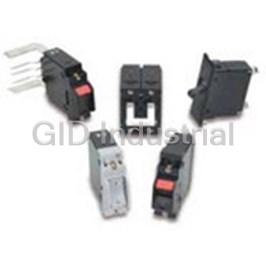
Circuit Breaker 1Pole 0.8A 277VAC/80VDC
AA1-B0-10-280-2D1-C
Part Number
AA1-B0-10-280-2D1-C
Price
Request Quote
Manufacturer
CARLING TECHNOLOGIES
Lead Time
Request Quote
Category
Circuit Protection » Circuit Breaker
Specifications
Manufacturer
Carling Technologies
Manufacturers Part #
AA1-B0-10-280-2D1-C
Industry Aliases
AA1-B0-10-280-2D1-C
Sub-Category
Circuit Breakers
Factory Pack Quantity
12
Datasheet

Extracted Text
A-Serie A-S s eries CIRCUIT BREAKER Well known for their proven reliability, Carling Technologies’ A-Series hydraulic magnetic circuit breakers are compact, temperature stable and designed for precision operation in OEM markets requiring general purpose as well as full load amp applications. When front panel operation and aesthetics demand a clean, contemporary design, the visi-rocker or paddle actuators are ideally suitable. A sealed toggle actuator style is also available and ideal for harsh environment applications requiring additional sealing protection. Optional rocker-guard and push- to-reset bezels, which help prevent inadvertent actuation, are also available. 1-6 poles; ratings from 0.02 to 50 amps, up to 277VAC or 80VDC; UL Recognized, UL Listed, UL1500, UL1077, TUV, VDE & CSA Product Highlights: Typical Applications: Up to 50 amps in a compact size Telecom/Datacom Various actuator styles Marine Sealed metal toggle option tested to Military MIL-PRF-55629C. Meets IP68 Renewable Energy Requirements Generators & Welder Carling Technologies, Inc. 60 Johnson Avenue, Plainville, CT 06062 Email: sales@carlingtech.com www.carlingtech.com Application Support: team2@carlingtech.com Phone: 860.793.9281 Fax: 860.793.9231 | A-Series Circuit Breaker - General Specifications 2 Electrical Mechanical Maximum Voltage 277VAC 50/60 Hz, 80VDC Endurance 10,000 ON-OFF operations @ 6 per Current Ratings Standard current coils: 0.100, minute; with rated Current & Voltage. 0.250, 0.500, 0.750, 1.00, 2.50, Trip Free All A-Series Circuit Breakers will trip 5.00, 7.50, 10.0, 15.0, 20.0, 25.0, on overload, even when the actuator 30.0, 35.0, 40.0, 50.0. Other ratings is forcibly held in the ON position. available - consult ordering Trip Indication The operating actuator moves scheme. positively to the OFF position when Standard Voltage Coils DC-6V, 12V; AC-120V, Other ratings an overload causes the circuit available, consult ordering scheme. breaker to trip. When mid-trip Auxiliary Switch Rating SPDT; 10.1 A - 250VAC, handle is specified, the handle 1.0 A-65VDC/0.5 A - 80 VDC, moves to the mid position on 0.1A - 125VAC (with gold contacts). electrical trip of the circuit breaker. Insulation Resistance Minimum: 100 Megohms at 500 When mid-trip handle with alarm VDC switch is specified, the handle Dielectric Strength UL, CSA - 1500V 60 Hz for one moves to the mid position & the minute between all electrically alarm switch actuates when the isolated terminals. A-Series rocker circuit breaker is electrically tripped. circuit breakers comply with the Physical 8mm spacing & 3750V dielectric requirements from hazardous Number of Poles 1 - 6 Poles (handle) and 1-3 poles voltage to operator accessible (rocker) at 30 Amps or less. 1 and 2 surfaces per EN 60950 and VDE poles at 31 Amps thru 50 Amps. 0805. Internal Circuit Config. Series, (with or without auxiliary Resistance, Impedance Values from Line to Load Terminal switch), Shunt and Relay with current - based on Series Trip Circuit or voltage trip coils, Dual Coil, Breaker. Switch Only with or without auxiliary RESISTANCE PER POLE VALUES switch. from Line to Load Terminals Weight Approximately 65 grams/pole. (Values Based on Series Trip Circuit Breaker) (Approximately 2.32 ounces/pole) Standard Colors Housing - Black; Actuator- See CURRENT TOLERANCE (AMPS) (%) Ordering Scheme. 0.10 - 5.0 15 Environmental 5.1 - 20.0 25 Designed and tested in accordance with requirements of specification MIL-PRF-55629 & MIL-STD-202 as follows: 20.1 - 50.0 35 Shock Withstands 100 Gs, 6ms, sawtooth while carrying rated current per Method 213, Test Condition “I”. Instantaneous and ultra-short curves tested @ 90% of rated current. Vibration Withstands 0.060” excursion from 10-55 Hz, and 10 Gs 55-500 Hz, at rated current per Method 204C, Test Condition A. Instantaneous and ultrashort curves tested at 90% of rated current. Pulse Tolerance Curves Moisture Resistance Method 106D; ten 24-hour cycles @ + 25°C to +65°C, 80-98% RH.56 days @ +85°C, 85% RH. Salt Spray Method 101, Condition A (90-95% RH @ 5% NaCl Solution, 96 hrs). Thermal Shock Method 107D, Condition A (Five cycles @ -55°C to +25°C to +85°C to +25°C). Operating Temperature -40° C to +85° C *Manufacturer reserves the right to change product specification without prior notice. Email: sales@carlingtech.com Application Support: team2@carlingtech.com Phone: (860) 793–9281 Fax: (860) 793–9231 www.carlingtech.com A-Series Circuit Breaker - General Specifications | 3 Electrical Tables Table A: Lists UL Recognized & CSA Accepted configurations and performance capabilities as a Component Supplementary Protector. A-SERIES TABLE A: COMPONENT SUPPLEMENTARY PROTECTORS Voltage Current Rating Short Circuit Capacity (Amps) Application Codes Circuit UL / CSA Construction General Max Full Load Configuration Notes Frequency Phase Purpose With Backup Without Rating Amps UL CSA Amps Fuse Backup Fuse 32 DC --- 0.02 - 15 --- --- 5000 TC1, OL1, U2 TC1, OL1, U2 65 DC --- 31 - 50 --- --- 7500 TC1, 2, OL1, U1 TC1, 2, OL1, U1 0.02 - 30 --- --- 7500 TC1, 2, OL1, U1 TC1, 2, OL1, U1 80 DC --- --- 31 - 50 --- 7500 TC1, 2, OL0, U1 TC1, 2, OL0, U1 125 50 / 60 1 0.02 - 30 --- --- 3000 TC1, OL1, U2 TC1, OL1, U2 Rocker Version 125 50 / 60 1 1 - 50 --- --- 2000 TC1, OL1, U2 TC1, OL1, U2 4 125 50 / 60 1 1 - 50 --- --- 1000 TC1, OL1, U2 TC3, OL1, U3 3 Rocker Version 125 / 250 50 / 60 1 0.02 - 30 --- --- 3000 TC1, 2, OL1, U2 TC1, 2, OL1, U2 Series 3 Handle 125 / 250 50 / 60 1 0.02 - 50 --- --- 3000 TC1, 2, OL1, U2 TC1, 2, OL1, U2 Single Pole Break 0.02 - 30 --- --- 1500 TC1, 2, OL0, U2 TC1, 2, OL0, U2 Two Pole Break 1 0.02 - 30 --- --- 3000 TC1, OL1, U2 TC1, OL1, U2 --- --- 3000 TC1, 2, OL0, U1 TC1, 2, OL0, U1 250 50 / 60 4 1 1 - 50 --- --- 1000 TC1, OL1, U2 TC3, OL1, U3 2 0.02 - 30 --- 5000 --- TC1, 2, OL1, C1 TC1, 2, OL1, C1 3 1 31 - 50 --- 2000 --- TC1, 2, OL1, C1 TC1, 2, OL1, C1 1 277 50 / 60 1 0.02 - 30 --- 5000 --- TC1, 2, OL1, C1 TC1, 2, OL1, C1 32 DC --- 0.02 - 50 --- --- 5000 TC1, OL1, U2 TC1, OL1, U2 65 DC --- 0.02 - 50 --- --- 7500 TC1, 2, OL1, U1 TC1, 2, OL1, U1 0.02 - 30 --- --- 7500 TC1, 2, OL1, U1 TC1, 2, OL1, U1 80 DC --- --- 31 - 50 --- 7500 TC1, 2, OL0, U1 TC1, 2, OL0, U1 Rocker Version 0.02 - 30 --- --- 3000 TC1, OL1, U2 TC1, OL1, U2 125 50 / 60 1 1 - 50 --- --- 2000 TC1, OL1, U2 TC1, OL1, U2 4 125 50 / 60 1 0.02 - 30 --- --- 1000 TC1, OL1, U2 TC3, OL1, U3 3 Rocker Version 125 / 250 50 / 60 1 0.02 - 30 --- --- 3000 TC1, 2, OL1, U1 TC1, 2, OL1, U1 Dual Coil 3 125 / 250 50 / 60 1 0.02 - 50 --- --- 3000 TC1, 2, OL1, U2 TC1, 2, OL1, U2 Single Pole Break 1 0.02 - 30 --- --- 1500 TC1, OL0, U2 TC1, OL0, U2 1 0.02 - 30 --- --- 3000 TC1, OL1, U2 TC1, OL1, U2 Two Pole Break 1 --- 31 - 50 --- 3000 TC1, 2, OL0, U1 TC1, 2, OL0, U1 250 50 / 60 4 1 1 - 50 --- --- 1000 TC1, OL1, U2 TC3, OL1, U3 2 0.02 - 30 --- 5000 --- TC1, 2, OL1, C1 TC1, 2, OL1, C1 3 1 31 - 50 --- 2000 --- TC1, 2, OL1, C1 TC1, 2, OL1, C1 1 277 50 / 60 1 0.02 - 30 --- 5000 --- TC1, 2, OL1, U1 TC1, 2, OL1, U1 80 DC --- 0.02 - 30 --- --- 7500 TC1, 2, OL1, U1 TC1, 2, OL1, U1 125 / 250 50 / 60 1 0.02 - 30 --- --- 3000 TC1, 2, OL1, U1 TC1, 2, OL1, U1 Shunt 1 0.02 - 30 --- --- 3000 TC1, 2, OL1, U1 TC1, 2, OL1, U1 250 50 / 60 2 3 0.02 - 30 --- 5000 --- TC1, 2, OL1, C1 TC1, 2, OL1, C1 1 277 50 / 60 1 0.02 - 30 --- 5000 --- TC1, 2, OL1, C1 TC1, 2, OL1, C1 80 DC --- 0.02 - 30 --- --- 7500 TC1, 2, OL1, U1 TC1, 2, OL1, U1 3 125 / 250 50 / 60 1 0.02 - 30 --- --- 3000 TC1, 2, OL1, U1 TC1, 2, OL1, U1 Relay 1 0.02 - 30 --- --- 3000 TC1, 2, OL1, U1 TC1, 2, OL1, U1 250 50 / 60 2 3 0.02 - 30 --- 5000 --- TC1, 2, OL1, C1 TC1, 2, OL1, C1 1 277 50 / 60 1 0.02 - 30 --- 5000 --- TC1, 2, OL1, C1 TC1, 2, OL1, C1 65 DC --- 0.02 - 50 --- 80 DC --- 0.02 - 30 --- Switch Only 1 --- 31 - 50 not applicable 250 50 / 60 3 0.02 - 50 --- 277 50 / 60 1 0.02 - 30 31 - 50 Notes: 1 Requires branch circuit backup with a UL LISTED Type K5 or RK5 fuse (15A minimum) at no more than 4 times the rating of the protector. 2 Same as note 1, except that backup fuse is limited to 80 A maximum. 3 2 pole protector required (with one pole per power line) for: 125/250 VAC, 1 pole protector required for : 125 VAC, 1Ø Power System. 4 Satisfies the requirements of clause 11.2.8.2.5 of CSA STD C22.2 No 100 for the use of supplementary protectors with portable generators. Email: sales@carlingtech.com Application Support: team2@carlingtech.com Email: sales@carlingtech.com Application Support: team2@carlingtech.com Phone: (860) 793–9281 Fax: (860) 793–9231 www.carlingtech.com Phone: (860) 793–9281 Fax: (860) 793–9231 www.carlingtech.com | 4 A-Series Circuit Breaker - General Specifications Electrical Tables Table B: Lists UL Recognized, CSA Accepted, VDE & TUV Certified configurations & performance capabilities as a Component Supplementary Protector. 1 3 2 3 2 3 2 Notes: 1 General Purpose Ratings for UL/CSA Only. 2 Requires branch circuit backup with a UL LISTED Type K5 or RK5 fuse (15A minimum) at no more than 4 times the rating of the protector. 3 Same as note 2, except that backup fuse is limited to 80 A maximum. 4 Satisfies the requirements of clause 11.2.8.2.5 of CSA STD C22.2 No 100 for the use of supplementary protectors with portable generators. Email: sales@carlingtech.com Application Support: team2@carlingtech.com Phone: (860) 793–9281 Fax: (860) 793–9231 www.carlingtech.com A-Series Circuit Breaker - General Specifications | 5 Electrical Tables Table C: Lists UL Recognized, CSA Accepted configurations and performance capabilities as Protectors, Supplementary for Marine Electrical and Fuel Systems (Guide PEQZ2, File E75596). Ignition Protected per UL 1500. UL Classified Small Craft Electrical Devices, Marine in accordance with ISO 8846 (Guide UZMK, File MQ1515) as Marine Supplementary Protectors. A-SERIES TABLE C: UL1500 (Marine Ignition Protected) CURRENT SHORT CIRCUIT VOLTAGE APPLICATION CODES CAPACITY (AMPS) RATING CIRCUIT CONFIGURATION WITHOUT BACKUP MAX. RATING FREQUENCY PHASE FULL LOAD AMPS UL CSA FUSE 1 SERIES DC --- 0.02 - 50 5000 TC1,OL1,U1 TC1,OL1,U1 14 1 DC --- 0.02 - 50 5000 TC1,OL1,U2 TC1,OL1,U2 32 65 DC --- 0.02 - 50 3000 TC1,OL1,U1 TC1,OL1,U1 125 50 / 60 1 0.02 - 50 3000 TC1,OL1,U2 TC1,OL1,U2 2 125 / 250 50 / 60 0.02 - 50 3000 TC1,OL1,U2 TC1,OL1,U2 1 250 50 / 60 1 0.02 - 30 1500 TC1,OL1,U1 TC1,OL1,U1 Notes: Notes: 1 Available with special catalog number only (consult factory). 2 2 pole protector required (with one per power line) for 125 / 250 VAC. 1 pole protector required for 125 VAC 1 phase power system 1 Available with Special Catalog Number Only (consult factory) 2 2 pole protector required (with one per power line) for 125 / 250 VAC. 1 pole protector required for 125 VAC 1 phase power system Table D: Lists UL Listed configurations and performance capabilities as Circuit Breakers for use in Communications Equipment (Guide DITT, File E189195), under UL489A. Notes: 1 Parallel Pole Construction Agency Certifications Component Supplementary UL Recognized CSA Accepted UL Standard 1077 Component Recognition Program Protector under Class 3215 30, as Protectors Supplementary File 047848 0 000 CSA (Guide CCN/QVNU2, File E75596) Standard C22.2 No. 235 Switches, Industrial Control EN60934, under License No. UL Standard 508 TUV Certified (Guide CCN/NRNT2, File E148683) R72103448 UL Standard 1500 Protectors, Supplementary for Marine Electrical & Fuel Systems VDE Certified EN60934, VDE 0642 under File (Guide PEQZ2, File E75596) No. 10537 Ignition Protection UL Listed UL Standard 489A Communications Equipment (Guide CCN/DITT, File E189195) Email: sales@carlingtech.com Application Support: team2@carlingtech.com Email: sales@carlingtech.com Application Support: team2@carlingtech.com Phone: (860) 793–9281 Fax: (860) 793–9231 www.carlingtech.com Phone: (860) 793–9281 Fax: (860) 793–9231 www.carlingtech.com | 6 A-Series Circuit Breaker - Handle UL Recognized – Ordering Scheme A A 3 B 0 10 450 1 B 1 C 1 2 3 4 5 6 7 8 9 10 11 Series Actuator Poles Circuit Aux/Alarm Frequency Current Rating Terminal Actuator Mounting/ Agency Switch & Delay Color Barriers Approval 1 SERIES 7 CURRENT RATING (AMPERES) A CODE AMPERES 020 0.020 225 0.250 420 2.000 611 11.000 025 0.025 230 0.300 522 2.250 711 11.500 1 2 ACTUATOR 030 0.030 235 0.350 527 2.750 612 12.000 A Handle, one per pole 035 0.035 240 0.400 430 3.000 712 12.500 B Handle, one per multipole unit 040 0.040 245 0.450 435 3.500 613 13.000 045 0.045 250 0.500 440 4.000 614 14.000 S Mid-Trip Handle, one per pole 050 0.050 255 0.550 445 4.500 615 15.000 T Mid-Trip Handle, one per pole & Alarm Switch 055 0.055 260 0.600 450 5.000 616 16.000 060 0.060 265 0.650 455 5.500 617 17.000 3 POLES 065 0.065 270 0.700 460 6.000 618 18.000 1 One 3 Three 5 Five 070 0.070 275 0.750 465 6.500 620 20.000 075 0.075 280 0.800 470 7.000 622 22.000 2 Two 4 Four 6 Six 080 0.080 285 0.850 475 7.500 624 24.000 085 0.085 290 0.900 480 8.000 625 25.000 090 0.090 295 0.950 485 8.500 630 30.000 4 CIRCUIT 8 2 3 095 0.095 410 1.000 490 9.000 635 35.000 A Switch Only (No Coil) F Relay Trip (Current) 8 210 0.100 512 1.250 495 9.500 640 40.000 3 B Series Trip (Current) G Relay Trip (Voltage) 8 215 0.150 415 1.500 610 10.000 645 45.000 3,4 C Series Trip (Voltage) H Dual Coil with Shunt Trip 8 220 0.200 517 1.750 710 10.500 650 50.000 3 D Shunt Trip (Current) Voltage Coil 6 3 3,4 OR VOLTAGE COIL (NORMAL RATED VOLTAGE) E Shunt Trip (Voltage) K Dual Coil with Relay Trip Voltage Coil CODE AMPERES A06 6 DC A32 32 DC J12 12 AC J65 65 AC A12 12 DC A48 48 DC J18 18 AC K20 120 AC 5 A18 18 DC A65 65 DC J24 24 AC L40 240 AC 5 AUXILIARY / ALARM SWITCH 5 S.P.S.T., 0.093 Q.C. Term. A24 24 DC J06 6 AC J48 48 AC 0 without Aux Switch (Gold Contacts) 1 S.P.D.T., 0.093 Q.C. Term. 7 S.P.S.T., 0.110 Q.C. Term. 2 S.P.D.T., 0.110 Q.C. Term. (Gold Contacts) 9 8 TERMINAL 4 S.P.D.T., 0.110 Q.C. Term. 8 S.P.S.T., 0.187 Q.C. Term. 10 11 1 Push-On 0.250 Tab (Q.C.) E Screw M4 (Bus Type) (Gold Contacts) 9 S.P.D.T., 0.187 Q.C. Term. 2 Screw 8-32 with upturned lugs F Screw M5 with upturned lugs 11 3 Screw 8-32 (Bus Type) & 30° bend 4 Screw 10-32 with upturned lugs G Screw M5 (Bus Type) & 30° bend 6 FREQUENCY & DELAY 11 11 5 Screw 10-32 (Bus Type) H Screw M5 (Bus Type) 03 DC 50/60Hz, Switch Only 30 DC, 50/60Hz Instantaneous 12 6 Screw 8-32 with upturned lugs L 0.250 Q.C./ Solder Lug 10 DC Instantaneous 31 DC, 50/60Hz Ultra Short 11 & 30° bend M M6 Threaded Stud 11 DC Ultra Short 32 DC, 50/60Hz Short 14 7 Screw 8-32 (Bus Type) Q Push-In Stud 12 DC Short 34 DC, 50/60Hz Medium & 30° bend R Screw M4 with upturned lugs 14 DC Medium 36 DC, 50/60Hz Long 8 Screw 10-32 with upturned lugs & 30° bend 7 16 DC Long 42 50/60Hz Short, Hi-Inrush 11 & 30° bend T Screw M4 (Bus Type) 7 20 50/60Hz Instantaneous 44 50/60Hz Medium, Hi-Inrush 9 Screw 10-32 (Bus Type) & 30° bend 7 21 50/60Hz Ultra Short 46 50/60Hz Long, Hi-Inrush 13 & 30° bend P Printed Circuit Board Terminals 7 22 50/60Hz Short 52 DC, Short,Hi-Inrush 13 B Screw M5 with upturned lugs S Push-On 0.110 Tab (Q.C.) 7 24 50/60Hz Medium 54 DC, Medium, Hi-Inrush C Screw M4 with upturned lugs 7 26 50/60Hz Long 56 DC, Long, Hi-Inrush Notes: 9 ACTUATOR COLOR & LEGEND 1 Actuator Code: Actuator Color I-O ON-OFF Dual Legend Color A: Handle tie pin spacer(s) and retainers provided un-assembled with multi-pole units. B: Handle location as viewed from front of breaker: White A B 1 Black 2 pole - left pole 3 pole - center pole 4 pole - two handles at center poles Black C D 2 White 5 pole - three handles at center poles 6 pole - four handles at center poles Red F G 3 White S: Handle moves to mid-position only upon electrical trip of the breaker. Available with Green H J 4 White circuit codes B, C, D, E, F, G, H and K. Blue K L 5 White T: Handle moves to mid-position and alarm switch activates only upon electrical trip of the Yellow M N 6 Black breaker. Available with circuit codes B & C. Gray P Q 7 Black 2 Switch Only circuits, rated up to 50 amps and 6 poles, and only available when tied to a Orange R S 8 Black protected pole (Circuit Code B, C, D or H.), For .02 to 30 amps, 15 Black (short handle) T U 9 White select Current Code 630. For 35 - 50 amps, select Current Code 650. 3 Available with terminal Codes 1, 2 and 3. Current Rating limited to 50A amps maximum. 4 Consult factory for available Dual Coil options, as special catalog number is required. With Shunt construction, Dual Coils will trip instantaneously on line voltage. Dual coils 10 MOUNTING / BARRIERS require 30VA minimum power to trip and are rated for intermittent duty only. MOUNTING STYLE BARRIERS 5 Auxiliary Switch breakers with Series Trip & Switch Only circuits: ≤ 30A - supplied with Threaded Insert, 2 per pole standard half shells. 35-50A - supplied with extended boat (B-Style) half shells. On multi-pole breakers, one auxiliary switch is supplied, mounted in the extreme right pole. 1 6-32 x 0.195 inches no 6 Separate pole type voltage coils not rated for continuous duty. Available only with delay A 6-32 x 0.195 inches yes codes 10 and 20. 2 ISO M3 x 5mm no 7 Available with Circuit Codes B & D only. VDE Certified to 30 amps. UL Recognized, CSA B ISO M3 x 5mm (multipole only) yes Accepted & TUV Certified to 50 amps. Front panel Snap-In, 0.75” wide bezel 8 VDE Certification available with single pole breakers with DC Delay only. UL Recognition 5 without Handleguard no and CSA Accepted available in one and two pole breakers. 9 Screw Terminals are recommended on ratings greater than 20 amps. Ratings over 30 6 without Handleguard (multipole only) yes amps are only available with Terminal Codes 5, 9, G, H, M and Q.. Front panel Snap-In, 0.96” wide bezel 10 Terminal Code 1: VDE Certification up to 25 amps and UL Recognition and CSA 7 without Handleguard, 1-pole 0.96” wide; no Certification up to 30 amps, but not recommended over 20 amps. multipole units have .105” bezel overhang on all sides 11 Terminal Codes 3, 5, E and H (Bus Type) with VDE, are supplied with Lock Washers, 8 without Handleguard, 1-pole 0.96” wide; yes and Terminal Code M (M6 Threaded Stud) with VDE is supplied with Lock and Flat Washers. These breakers are only VDE Certified when the washers are used. (multipole only) .105” bezel overhang on all sides 12 Terminal Code L: VDE Certified available up to 12A. UL Recognized & CSA Accepted available up to 30A. 13 Single pole breakers with Terminal Code P (Printed Circuit Board) are available up to 30 amps with VDE Certification and 50 amps with UL Recognition and CSA Accepted, with Circuit 11 AGENCY APPROVAL Codes A, B and C. Two pole breakers with Terminal Code P (Printed Circuit Board) are C UL Recognized & CSA Accepted available up to 40 amps with UL Recognition and CSA Accepted with Circuit Codes A, B and C. D VDE Certified, UL Recognized & CSA Accepted 14 Terminal Code Q not available with VDE certification. E TUV Certified, UL Recognized & CSA Accepted 15 Single pole only. I UL Recognized STD 1077, UL Recognized 1500 (ignition protected), & CSA Accepted Email: sales@carlingtech.com Application Support: team2@carlingtech.com Phone: (860) 793–9281 Fax: (860) 793–9231 www.carlingtech.com A-Series Circuit Breaker - Handle UL489A – Ordering Scheme | 7 A A 1 B 0 14 450 1 B 1 M T 1 2 3 4 5 6 7 8 9 10 11 12 Series Actuator Poles Circuit Aux/Alarm Frequency Current Rating Terminal Actuator Mounting/ Max. Appl. Agency Switch & Delay Color Barriers Rating Approval 1 SERIES 9 ACTUATOR COLOR & LEGEND Actuator Color ON-OFF Dual Legend Color A White B 1 Black Black D 2 White 1 2 ACTUATOR Red G 3 White Green J 4 White A Handle, one per pole Blue L 5 White S Mid-Trip Handle, one per pole Yellow N 6 Black T Mid-Trip Handle, one per pole & Alarm Switch Gray Q 7 Black Orange S 8 Black 10 2 Black (short handle) U 9 White 3 POLES 1 One 2 Two 10 MOUNTING / BARRIERS 3 Three MOUNTING STYLE BARRIERS 4 Four Threaded Insert, 2 per pole 1 6-32 x 0.195 inches no 4 CIRCUIT A 6-32 x 0.195 inches yes 2 ISO M3 x 5mm no B Series Trip (Current) B ISO M3 x 5mm (multipole only) yes Front panel Snap-In, 0.75” wide bezel 2 5 AUXILIARY/ALARM SWITCH 7 S.P.S.T., 0.110 Q.C. Term. 5 without Handleguard no 0 without Aux Switch (Gold Contacts) 6 without Handleguard (multipole only) yes 1 S.P.D.T., 0.093 Q.C. Term. 8 S.P.S.T., 0.187 Q.C. Term. Front panel Snap-In, 0.96” wide bezel 2 S.P.D.T., 0.110 Q.C. Term. 9 S.P.D.T., 0.187 Q.C. Term. 7 without Handleguard, 1-pole 0.96” wide; no multipole units have .105” bezel overhang on all sides 8 without Handleguard, 1-pole 0.96” wide; yes 6 FREQUENCY & DELAY (multipole only) .105” bezel overhang on all sides 3 11 DC Ultra Short 52 DC, Short,Hi-Inrush 3 12 DC Short 54 DC, Medium, Hi-Inrush 3 14 DC Medium 56 DC, Long, Hi-Inrush 11 MAXIMUM APPLICATION RATING 16 DC Long M 80 DC 7 CURRENT RATING (AMPERES) 12 AGENCY APPROVAL CODE AMPERES T UL489A Listed 210 0.100 285 0.850 455 5.500 613 13.000 K UL489A Listed, VDE Certified 215 0.150 290 0.900 460 6.000 614 14.000 J UL489A Listed, TUV Certified 220 0.200 295 0.950 465 6.500 615 15.000 225 0.250 410 1.000 470 7.000 616 16.000 230 0.300 512 1.250 475 7.500 617 17.000 Notes: 235 0.350 415 1.500 480 8.000 618 18.000 1 Actuator Code: 240 0.400 517 1.750 485 8.500 620 20.000 A: Handle tie pin spacer(s) and retainers provided un-assembled with multi-pole units. 245 0.450 420 2.000 490 9.000 622 22.000 S: Handle moves to mid-position only upon electrical trip of the breaker. T: Handle moves to mid-position and alarm switch activates only upon electrical trip of the 250 0.500 522 2.250 495 9.500 624 24.000 breaker. 255 0.550 527 2.750 610 10.000 625 25.000 2 On multi-pole breakers, one auxiliary switch is supplied, mounted in the extreme right pole. 260 0.600 430 3.000 710 10.500 630 30.000 3 VDE Certified to 30 amps. UL489A Listed to 50 amps. 3 265 0.650 435 3.500 611 11.000 635 35.000 4 VDE Certification available with single pole breakers only. UL489A Listing available with one 3 270 0.700 440 4.000 711 11.500 640 40.000 and two pole breakers. 3 275 0.750 445 4.500 612 12.000 645 45.000 5 Screw Terminals are recommended on ratings greater than 20 amps. Ratings over 30 amps 3 280 0.800 450 5.000 712 12.500 650 50.000 are only available with Terminal Codes 5, 9 G, H, M and Q. 6 Terminal Code 1 (Push-On) available up to 25 amps with VDE Certification and 30 amps with UL489A Listing, but is not recommended over 20 amps. 7 Terminal Codes 3, 5 and H (Bus Type) with VDE, are supplied with Lock Washers, and 5 8 TERMINAL Terminal Code M (M6 Threaded Stud) with VDE is supplied with Lock and Flat Washers. 6 1 Push-On 0.250 Tab (Q.C.) 9 Screw 10-32 (Bus Type) These breakers are only VDE Certified when the washers are used. 2 Screw 8-32 with upturned lugs & 30° bend 8 Single pole breakers with Terminal Code P (Printed Circuit Board) are available up to 7 3 Screw 8-32 (Bus Type) B Screw M5 with upturned lugs 30 amps with VDE Certification and 50 amps with UL489A Listing. 9 Terminal Code Q not available with VDE certification. 4 Screw 10-32 with upturned lugs F Screw M5 with upturned lugs 10 Single pole only. 7 5 Screw 10-32 (Bus Type) & 30° bend 6 Screw 8-32 with upturned lugs G Screw M5 (Bus Type) & 30° bend & 30° bend H Screw M5 (Bus Type) 7 7 Screw 8-32 (Bus Type) M M6 Threaded Stud 8 & 30° bend P Printed Circuit Board Terminals 9 8 Screw 10-32 with upturned lugs Q Push-In Stud & 30° bend Email: sales@carlingtech.com Application Support: team2@carlingtech.com Email: sales@carlingtech.com Application Support: team2@carlingtech.com Phone: (860) 793–9281 Fax: (860) 793–9231 www.carlingtech.com Phone: (860) 793–9281 Fax: (860) 793–9231 www.carlingtech.com | 8 A-Series Circuit Breaker - Handle WORLD – Ordering Scheme A A 3 B 0 14 450 1 A 1 P 1 2 3 4 5 6 7 8 9 10 11 Series Actuator Poles Circuit Aux/Alarm Frequency Current Rating Terminal Actuator Mounting/ Agency Switch & Delay Color Barriers Approval 9 1 SERIES 8 TERMINAL 10 A 1 Push-On 0.250 Tab (Q.C.) B Screw M5 with upturned lugs 2 Screw 8-32 with upturned lugs C Screw M4 with upturned lugs 11 11 3 Screw 8-32 (Bus Type) E Screw M4 (Bus Type) 1 2 ACTUATOR 4 Screw 10-32 with upturned lugs F Screw M5 with upturned lugs A Handle, one per pole 11 5 Screw 10-32 (Bus Type) & 30° bend B Handle, one per multipole unit 6 Screw 8-32 with upturned lugs G Screw M5 (Bus Type) & 30° bend S Mid-Trip Handle, one per pole 11 & 30° bend H Screw M5 (Bus Type) T Mid-Trip Handle, one per pole & Alarm Switch 7 Screw 8-32 (Bus Type) R Screw M4 with upturned lugs & 30° bend & 30° bend 11 8 Screw 10-32 with upturned lugs T Screw M4 (Bus Type) 3 POLES & 30° bend & 30° bend 1 One 3 Three 5 Five 9 Screw 10-32 (Bus Type) 2 Two 4 Four 6 Six & 30° bend 4 CIRCUIT 2 3 A Switch Only (No Coil) D Shunt Trip (Current) 9 ACTUATOR COLOR & LEGEND 3 B Series Trip (Current) E Shunt Trip (Voltage) Actuator Color I-O Dual Legend Color 3,4 C Series Trip (Voltage) H Dual Coil with Shunt Trip White A 1 Black Black C 2 White Voltage Coil Red F 3 White Green H 4 White 5 Blue K 5 White 5 AUXILIARY / ALARM SWITCH Yellow M 6 Black 0 without Aux Switch Gray P 7 Black 2 S.P.D.T., 0.110 Q.C. Term. Orange R 8 Black 4 S.P.D.T., 0.110 Q.C. Term. (Gold Contacts) 15 Black (short handle) T 9 White 10 MOUNTING / BARRIERS 6 FREQUENCY & DELAY MOUNTING STYLE BARRIERS 03 DC 50/60Hz, Switch Only 30 DC, 50/60Hz Instantaneous Threaded Insert, 2 per pole 10 DC Instantaneous 31 DC, 50/60Hz Ultra Short 1 6-32 x 0.195 inches no 11 DC Ultra Short 32 DC, 50/60Hz Short A 6-32 x 0.195 inches yes 12 DC Short 34 DC, 50/60Hz Medium 2 ISO M3 x 5mm no 14 DC Medium 36 DC, 50/60Hz Long B ISO M3 x 5mm (multipole only) yes 7 16 DC Long 42 50/60Hz Short, Hi-Inrush Front panel Snap-In, 0.75” wide bezel 7 20 50/60Hz Instantaneous 44 50/60Hz Medium, Hi-Inrush 5 without Handleguard no 7 21 50/60Hz Ultra Short 46 50/60Hz Long, Hi-Inrush 6 without Handleguard (multipole only) yes 7 22 50/60Hz Short 52 DC, Short,Hi-Inrush Front panel Snap-In, 0.96” wide bezel 7 24 50/60Hz Medium 54 DC, Medium, Hi-Inrush 7 without Handleguard, 1-pole 0.96” wide; no 7 26 50/60Hz Long 56 DC, Long, Hi-Inrush multipole units have .105” bezel overhang on all sides 8 without Handleguard, 1-pole 0.96” wide; yes (multipole only) .105” bezel overhang on all sides 7 CURRENT RATING (AMPERES) CODE AMPERES 210 0.100 285 0.850 455 5.500 613 13.000 11 AGENCY APPROVAL 215 0.150 290 0.900 460 6.000 614 14.000 P TUV Certified, UL Recognized & CSA Accepted 220 0.200 295 0.950 465 6.500 615 15.000 Q UL Recognized STD 1077, UL Recognized 1500 (ignition protected), 225 0.250 410 1.000 470 7.000 616 16.000 & CSA Accepted 230 0.300 512 1.250 475 7.500 617 17.000 235 0.350 415 1.500 480 8.000 618 18.000 240 0.400 517 1.750 485 8.500 620 20.000 Notes: 245 0.450 420 2.000 490 9.000 622 22.000 1 Actuator Code: 250 0.500 522 2.250 495 9.500 624 24.000 A: Handle tie pin spacer(s) and retainers provided unassembled with multi-pole units. S: Handle moves to mid-position only upon electrical trip of the breaker. Available with circuit 255 0.550 527 2.750 610 10.000 625 25.000 codes B, C, D, E, and H. 260 0.600 430 3.000 710 10.500 630 30.000 8 T: Handle moves to mid-position and alarm switch activates only upon electrical trip of the 265 0.650 435 3.500 611 11.000 635 35.000 breaker. Available with circuit codes B & C. 8 270 0.700 440 4.000 711 11.500 640 40.000 2 Switch Only circuits, rated up to 50 amps and 6 poles, and only available when tied to a 8 275 0.750 445 4.500 612 12.000 645 45.000 protected pole (Circuit Code B, C, D or H.), For .01 to 30 amps, select Current Code 630. 8 280 0.800 450 5.000 712 12.500 650 50.000 For 35 - 50 amps, select Current Code 650. 6 OR VOLTAGE COIL (NORMAL RATED VOLTAGE) 3 Available with terminal Codes 1, 2 and 3. Current Rating limited to 30 amps maximum. 4 Consult factory for available Dual Coil options, as special catalog number is required. CODE AMPERES With Shunt construction, Dual Coils will trip instantaneously on line voltage. Dual coils require A06 6 DC A32 32 DC J12 12 AC J65 65 AC 30VA minimum power to trip and are rated for intermittent duty only. A12 12 DC A48 48 DC J18 18 AC K20 120 AC 5 On multi-pole breakers, one auxiliary switch is supplied, mounted in the extreme right pole. A18 18 DC A65 65 DC J24 24 AC L40 240 AC 6 Separate pole type voltage coils not rated for continuous duty. Available only with delay A24 24 DC J06 6 AC J48 48 AC codes 10, 20 & 30. 7 Available with Circuit Codes B & D only. VDE Certified to 30 amps. UL Recognized, CSA Accepted & TUV Certified to 50 amps. 8 Available up to two poles with AC or DC delays. 9 Screw Terminals are recommended on ratings greater than 20 amps. Ratings over 30 amps are only available with Terminal Codes 5, 9, G and H. 10 Terminal Code 1: TUV Certification up to 30 amps, but not recommended over 20 amps. 11 Terminal Codes 3, 5 , 7, 9, E, G and H (Bus Type) are supplied with Lock Washers. These breakers are only TUV Certified when the washers are used. 12 Single pole only. Email: sales@carlingtech.com Application Support: team2@carlingtech.com Phone: (860) 793–9281 Fax: (860) 793–9231 www.carlingtech.com A-Series Circuit Breaker - Rocker UL489A – Ordering Scheme | 9 A F 1 B 0 14 450 1 3 1 M T 8 9 10 11 12 1 2 3 4 5 6 7 Terminal Actuator Mounting/ Max. Appl. Agency Series Actuator Poles Circuit Aux/Alarm Frequency Current Rating Switch & Delay Color Barriers Rating Approval 5 1 SERIES 8 TERMINAL 6 A 1 Push-On 0.250 Tab (Q.C.) 9 Screw 10-32 (Bus Type) 2 Screw 8-32 with upturned lugs & 30° bend 7 3 Screw 8-32 (Bus Type) B Screw M5 with upturned lugs 1 2 ACTUATOR 4 Screw 10-32 with upturned lugs F Screw M5 with upturned lugs Two Color Visi-Rocker Push-To-Reset, Visi-Rocker 7 5 Screw 10-32 (Bus Type) & 30° bend C Indicate ON, vertical legend N Indicate OFF, vertical legend 6 Screw 8-32 with upturned lugs G Screw M5 (Bus Type) & 30° bend D Indicate ON, horizontal legend O Indicate OFF, horizontal legend & 30° bend H Screw M5 (Bus Type) F Indicate OFF, vertical legend 7 7 Screw 8-32 (Bus Type) M M6 Threaded Stud G Indicate OFF, horizontal legend 8 & 30° bend P Printed Circuit Board Terminals Single color Push-To-Reset , Single color 9 8 Screw 10-32 with upturned lugs Q Push-In Stud J Vertical legend R Vertical legend & 30° bend K Horizontal legend U Horizontal legend 9 ACTUATOR COLOR & LEGEND Actuator or Marking: Marking Color 10 10 Visi-Color ON-OFF Dual Single Color Visi-Rocker White B 1 Black White Black D 2 White n/a Red G 3 White Red Green J 4 White Green Blue L 5 White Blue Yellow N 6 Black Yellow Gray Q 7 Black Gray Orange S 8 Black Orange 11 10 MOUNTING / BARRIERS STANDARD ROCKER BEZEL BARRIERS Threaded Insert, 2 per pole 1 6-32 x 0.195 inches no A 6-32 X 0.195 inches (multi-pole units only) yes 2 3 POLES 2 ISO M3 x 5mm no 1 One B ISO M3 x 5mm (multi-pole units only) yes 2 Two ROCKERGUARD & PUSH-TO-RESET BEZEL 3 Three Threaded Insert, 2 per pole 3 6-32 x 0.195 inches no C 6-32 x 0.195 inches (multi-pole units only) yes 4 CIRCUIT 4 ISO M3 x 5mm no B Series Trip (Current) D ISO M3 x 5mm (multi-pole units only) yes FRONT PANEL SNAP-IN BRACKET, 0.744” [18.90mm] wide bezel 8 without Rockerguard (single pole units only) no 2 5 AUXILIARY / ALARM SWITCH 7 S.P.S.T., 0.110 Q.C. Term. H with Rockerguard (single pole units only) no 0 without Aux Switch (Gold Contacts) FRONT PANEL SNAP-IN BRACKET, 0.96” [24.48mm] wide bezel 1 S.P.D.T., 0.093 Q.C. Term. 8 S.P.S.T., 0.187 Q.C. Term. 9 without Rockerguard (single pole units only) no 2 S.P.D.T., 0.110 Q.C. Term. 9 S.P.D.T., 0.187 Q.C. Term. J with Rockerguard (single pole units only) no 6 FREQUENCY & DELAY 11 MAXIMUM APPLICATION RATING 11 DC Ultra Short 52 DC, Short,Hi-Inrush M 80 DC 12 DC Short 54 DC, Medium, Hi-Inrush 14 DC Medium 56 DC, Long, Hi-Inrush 16 DC Long 12 AGENCY APPROVAL T UL489A Listed K UL489A Listed, VDE Certified 7 CURRENT RATING (AMPERES) J UL489A Listed, TUV Certified CODE AMPERES 210 0.100 285 0.850 455 5.500 613 13.000 Notes: 215 0.150 290 0.900 460 6.000 614 14.000 1 Push-To-Reset actuators have OFF portion of rocker shrouded. 220 0.200 295 0.950 465 6.500 615 15.000 2 Multi-pole breakers have all breakers identical except when specifying Auxiliary switch and/or 225 0.250 410 1.000 470 7.000 616 16.000 mixed poles, and have one rocker per breaker. 3 Auxiliary Switch breakers with Series Trip circuits: ≤ 30A, are supplied with standard half shells. 230 0.300 512 1.250 475 7.500 617 17.000 30-50A are supplied with extended boat (B-Style) half shells. 235 0.350 415 1.500 480 8.000 618 18.000 4 VDE Certification available with single pole breakers only. UL489A Listing available with one 240 0.400 517 1.750 485 8.500 620 20.000 and two pole breakers. 245 0.450 420 2.000 490 9.000 622 22.000 5 Screw Terminals are recommended on ratings greater than 20 amps. Ratings over 30 amps 250 0.500 522 2.250 495 9.500 624 24.000 are only available with Terminal Codes 5, 9, G, H, M and Q. 255 0.550 527 2.750 610 10.000 625 25.000 6 Terminal Code 1 (Push-On) available up to 25 amps with TUV or VDE Certification and 30 260 0.600 430 3.000 710 10.500 630 30.000 amps with UL489A Listing, but is not recommended over 20 amps. 4 265 0.650 435 3.500 611 11.000 635 35.000 7 Terminal Codes 3, 5 and H (Bus Type) with TUV or VDE, are supplied with Lock Washers, and 4 270 0.700 440 4.000 711 11.500 640 40.000 Terminal Code M (M6 Threaded Stud) with VDE is supplied with Lock and Flat Washers. 4 These breakers are only TUV or VDE Certified when the washers are used. 275 0.750 445 4.500 612 12.000 645 45.000 4 8 Single pole breakers with Terminal Code P (Printed Circuit Board) are available up to 30 amps 280 0.800 450 5.000 712 12.500 650 50.000 with VDE Certification and 50 amps with UL489A Listing. 9 Terminal Code Q not available with VDE certification. 10 Color shown is Visi and Legend with remainder of rocker black. Dual = ON-OFF/I-O legend. 11 Legend on Push-to-reset bezel/shroud is white with single color actuator codes R & U. Legend on Push-To-Reset bezel/shroud matches Visi-Color of rocker with actuator codes N & O. Rockerguard available with actuator codes C through K Email: sales@carlingtech.com Application Support: team2@carlingtech.com Email: sales@carlingtech.com Application Support: team2@carlingtech.com Phone: (860) 793–9281 Fax: (860) 793–9231 www.carlingtech.com Phone: (860) 793–9281 Fax: (860) 793–9231 www.carlingtech.com | 10 A-Series Circuit Breaker - Handle – Circuit & Terminal Diagrams Circuit & Terminal Diagrams: in. [mm] Notes: 1 All dimensions are in inches [millimeters]. 2 Tolerance ±.020 [.51] unless otherwise specified. 3 Alarm Switch available with .110 x .020 Q.C. & Solder Lug Terminals Only. Email: sales@carlingtech.com Application Support: team2@carlingtech.com Phone: (860) 793–9281 Fax: (860) 793–9231 www.carlingtech.com A-Series Circuit Breaker - Handle – Circuit & Terminal Diagrams | 11 Circuit & Terminal Diagrams: in. [mm] Notes: 1 All dimensions are in inches [millimeters]. 2 Tolerance ±.020 [.51] unless otherwise specified. 3 Alarm Switch available with .110 x .020 QC & solder lug terminals only. Email: sales@carlingtech.com Application Support: team2@carlingtech.com Email: sales@carlingtech.com Application Support: team2@carlingtech.com Phone: (860) 793–9281 Fax: (860) 793–9231 www.carlingtech.com Phone: (860) 793–9281 Fax: (860) 793–9231 www.carlingtech.com | 12 A-Series Circuit Breaker - Handle - Dimensional Specifications Dimensional Specifications: in. [mm] Notes: 1 All dimensions are in inches [millimeters]. 2 Tolerance ± 0.20 [.51] unless otherwise specified. 3 For agency code P = .150 [3.81]. Email: sales@carlingtech.com Application Support: team2@carlingtech.com Phone: (860) 793–9281 Fax: (860) 793–9231 www.carlingtech.com A-Series Circuit Breaker - Handle – Front Panel Snap-In Mounting Style 5 - Dimensional Specifications | 13 Dimensional Specifications: in. [mm] Notes: 1 All dimensions are in inches [millimeters]. 2 Recommended panel thickness: .040 [1.02] to .100 [2.54]. 3 Tolerance ±.020 [.51] unless otherwise specified. Email: sales@carlingtech.com Application Support: team2@carlingtech.com Email: sales@carlingtech.com Application Support: team2@carlingtech.com Phone: (860) 793–9281 Fax: (860) 793–9231 www.carlingtech.com Phone: (860) 793–9281 Fax: (860) 793–9231 www.carlingtech.com | 14 A-Series Circuit Breaker - Handle – Front Panel Snap-In Mounting Style 7 - Dimensional Specifications Dimensional Specifications: in. [mm] Notes: 1 All dimensions are in inches [millimeters]. 2 Recommended panel thickness: .040 [1.02] to .100 [2.54]. 3 Tolerance ±.020 [.51] unless otherwise specified. Email: sales@carlingtech.com Application Support: team2@carlingtech.com Phone: (860) 793–9281 Fax: (860) 793–9231 www.carlingtech.com A-Series Circuit Breaker - Sealed Toggle UL Recognized – Ordering Scheme | 15 A M 1 B 0 10 450 1 0 1 C 1 2 3 4 5 6 7 8 9 10 11 Circuit Terminal Actuator Mounting/ Agency Series Actuator Poles Aux/Alarm Frequency Current Rating Color Barriers Approval Switch & Delay 9 1 SERIES 8 TERMINAL 10 A 1 Push-On 0.250 Tab (Q.C.) E Screw M4 (Bus Type) 2 Screw 8-32 with upturned lugs F Screw M5 with upturned lugs 3 Screw 8-32 (Bus Type) & 30° bend 1 2 ACTUATOR 4 Screw 10-32 with upturned lugs G Screw M5 (Bus Type) & 30° bend M Sealed Toggle, one per unit 5 Screw 10-32 (Bus Type) H Screw M5 (Bus Type) 12 6 Screw 8-32 with upturned lugs L 0.250 Q.C./ Solder Lug & 30° bend M M6 Threaded Stud 3 POLES 7 Screw 8-32 (Bus Type) Q Push-In Stud 1 One & 30° bend R Screw M4 with upturned lugs 2 Two 8 Screw 10-32 with upturned lugs & 30° bend 3 Three & 30° bend T Screw M4 (Bus Type) 9 Screw 10-32 (Bus Type) & 30° bend 12 & 30° bend P Printed Circuit Board Terminals 4 CIRCUIT 2 3 B Screw M5 with upturned lugs S Push-On 0.110 Tab (Q.C.) A Switch Only (No Coil) F Relay Trip (Current) 3 C Screw M4 with upturned lugs B Series Trip (Current) G Relay Trip (Voltage) 3,4 C Series Trip (Voltage) H Dual Coil with Shunt Trip 3 D Shunt Trip (Current) Voltage Coil 3 3,4 E Shunt Trip (Voltage) K Dual Coil with Relay Trip 9 LEGEND PLATE Voltage Coil 0 No legend plate 5 5 AUXILIARY / ALARM SWITCH 5 S.P.S.T., 0.093 Q.C. Term. 10 MOUNTING / BARRIERS 0 without Aux Switch (Gold Contacts) MOUNTING STYLE BARRIERS 1 S.P.D.T., 0.093 Q.C. Term. 7 S.P.S.T., 0.110 Q.C. Term. 1 Standard Hex Nut no 2 S.P.D.T., 0.110 Q.C. Term. (Gold Contacts) A Standard Hex Nut (multipole only) yes 4 S.P.D.T., 0.110 Q.C. Term. 8 S.P.S.T., 0.187 Q.C. Term. (Gold Contacts) 9 S.P.D.T., 0.187 Q.C. Term. 11 AGENCY APPROVAL C UL Recognized & CSA Accepted 6 FREQUENCY & DELAY I UL Recognized STD 1077, UL Recognized 1500 (ignition protected), 03 DC 50/60Hz, Switch Only 30 DC, 50/60Hz Instantaneous & CSA Accepted 10 DC Instantaneous 31 DC, 50/60Hz Ultra Short 11 DC Ultra Short 32 DC, 50/60Hz Short 12 DC Short 34 DC, 50/60Hz Medium Notes: 14 DC Medium 36 DC, 50/60Hz Long 1 Actuator Code M: Handle location as viewed from front of panel: 7 16 DC Long 42 50/60Hz Short, Hi-Inrush 2 pole - right pole 3 pole - center pole 7 20 50/60Hz Instantaneous 44 50/60Hz Medium, Hi-Inrush 2 Switch Only circuits, rated up to 50 amps and 3 poles. Only available when tied to a 7 21 50/60Hz Ultra Short 46 protected pole. For .02 to 30 amps, select Current Code 630. For 35 - 50 amps, 50/60Hz Long, Hi-Inrush 7 select Current Code 650. 22 50/60Hz Short 52 DC, Short,Hi-Inrush 3 Available with terminal Codes 1, 2 and 3. Current Rating limited to 30 amps maximum. 7 24 50/60Hz Medium 54 DC, Medium, Hi-Inrush 4 Consult factory for available Dual Coil options, as special catalog number is required. With 7 26 50/60Hz Long 56 DC, Long, Hi-Inrush Shunt construction, Dual Coils will trip instantaneously on line voltage. Dual coils require 30VA minimum power to trip and are rated for intermittent duty only. 5 Auxiliary Switch available on Series Trip & Switch Only circuits, limited to 30 amps. On multi-pole breakers, one auxiliary switch is supplied, mounted in the extreme right pole. 7 CURRENT RATING (AMPERES) 6 Voltage coils not rated for continuous duty. Available only with delay codes 10 and 20. CODE AMPERES 7 Available with Circuit Codes B & D only. VDE Certified to 30 amps. UL Recognized, CSA 020 0.020 230 0.300 425 2.500 612 12.000 Accepted & TUV Certified to 50 amps. 025 0.025 235 0.350 527 2.750 712 12.500 8 UL Recognition and CSA Certification available on one and two pole breakers. 030 0.030 240 0.400 430 3.000 613 13.000 9 Screw Terminals are recommended on ratings greater than 20 amps. Ratings over 035 0.035 245 0.450 435 3.500 614 14.000 30 amps are only available with Terminal Codes 5, 9, B, F, G, H, M and Q. 040 0.040 250 0.500 440 4.000 615 15.000 10 Terminal Code 1: UL Recognition and CSA Certification up to 30 amps, but not recommended over 20 amps. 045 0.045 255 0.550 445 4.500 616 16.000 11 Terminal Code L : available up to 30A. 050 0.050 260 0.600 450 5.000 617 17.000 12 Single pole breakers with Terminal Code P (Printed Circuit Board) are available up to 055 0.055 265 0.650 455 5.500 618 18.000 50 amps, with Circuit Codes A, B and C. Two pole breakers with Terminal Code P 060 0.060 270 0.700 460 6.000 620 20.000 (Printed Circuit Board) are available up to 40 amps with Circuit Codes A, B and C. 065 0.065 275 0.750 465 6.500 622 22.000 070 0.070 280 0.800 470 7.000 624 24.000 075 0.075 285 0.850 475 7.500 625 25.000 080 0.080 290 0.900 480 8.000 630 30.000 8 085 0.085 295 0.950 485 8.500 635 35.000 8 090 0.090 410 1.000 490 9.000 640 40.000 8 095 0.095 512 1.250 495 9.500 645 45.000 8 210 0.100 415 1.500 610 10.000 650 50.000 215 0.150 517 1.750 710 10.500 220 0.200 420 2.000 611 11.000 225 0.250 522 2.250 711 11.500 6 OR VOLTAGE COIL (NORMAL RATED VOLTAGE) CODE AMPERES A06 6 DC A32 32 DC J12 12 AC J65 65 AC A12 12 DC A48 48 DC J18 18 AC K20 120 AC A18 18 DC A65 65 DC J24 24 AC L40 240 AC A24 24 DC J06 6 AC J48 48 AC Email: sales@carlingtech.com Application Support: team2@carlingtech.com Email: sales@carlingtech.com Application Support: team2@carlingtech.com Phone: (860) 793–9281 Fax: (860) 793–9231 www.carlingtech.com Phone: (860) 793–9281 Fax: (860) 793–9231 www.carlingtech.com | 16 A-Series Circuit Breaker - Sealed Toggle - Dimensional Specifications Dimensional Specifications: in. [mm] Notes: 1 All dimensions are in inches [millimeters]. 2 Tolerance ±.020 [.51] unless otherwise specified. Email: sales@carlingtech.com Application Support: team2@carlingtech.com Phone: (860) 793–9281 Fax: (860) 793–9231 www.carlingtech.com A-Series Circuit Breaker - Rocker UL Recognized – Ordering Scheme | 17 A F 1 B 0 24 630 2 3 1 D 1 2 3 4 5 6 7 8 9 10 11 Agency Series Actuator Poles Circuit Aux/Alarm Frequency Current Rating Terminal Actuator Mounting/ Approval Switch & Delay Color Barriers 1 SERIES 7 CURRENT RATING (AMPERES) A CODE AMPERES 020 0.020 225 0.250 420 2.000 611 11.000 025 0.025 230 0.300 522 2.250 711 11.500 1 2 ACTUATOR 030 0.030 235 0.350 527 2.750 612 12.000 Two Color Visi-Rocker 035 0.035 240 0.400 430 3.000 712 12.500 C Indicate ON, vertical legend 040 0.040 245 0.450 435 3.500 613 13.000 D Indicate ON, horizontal legend 045 0.045 250 0.500 440 4.000 614 14.000 F Indicate OFF, vertical legend 050 0.050 255 0.550 445 4.500 615 15.000 G Indicate OFF, horizontal legend 055 0.055 260 0.600 450 5.000 616 16.000 H Indicate OFF, no legend 060 0.060 265 0.650 455 5.500 617 17.000 Push-To-Reset, Visi-Rocker 065 0.065 270 0.700 460 6.000 618 18.000 N Indicate OFF, vertical legend 070 0.070 275 0.750 465 6.500 620 20.000 O Indicate OFF, horizontal legend 075 0.075 280 0.800 470 7.000 622 22.000 P Indicate OFF, no legend 080 0.080 285 0.850 475 7.500 624 24.000 Single color 085 0.085 290 0.900 480 8.000 625 25.000 J Vertical legend 090 0.090 295 0.950 485 8.500 630 30.000 K Horizontal legend 8 095 0.095 410 1.000 490 9.000 635 35.000 L No legend 8 210 0.100 512 1.250 495 9.500 640 40.000 Push-To-Reset , Single color 8 215 0.150 415 1.500 610 10.000 645 45.000 R Vertical legend 8 220 0.200 517 1.750 710 10.500 650 50.000 U Horizontal legend 8 OR VOLTAGE COIL (NORMAL RATED VOLTAGE) V No legend CODE AMPERES A06 6 DC A32 32 DC J12 12 AC J65 65 AC A12 12 DC A48 48 DC J18 18 AC K20 120 AC 3 POLES A18 18 DC A65 65 DC J24 24 AC L40 240 AC 1 One 2 Two 3 Three A24 24 DC J06 6 AC J48 48 AC 4 4 CIRCUIT F Relay Trip (Current) 3 4 11 A Switch Only (No Coil) G Relay Trip (Voltage) 8 TERMINAL 4,5 12 13 B Series Trip (Current) H Dual Coil with Shunt Trip 1 Push-On 0.250 Tab (Q.C.) E Screw M4 (Bus Type) C Series Trip (Voltage) Voltage Coil 2 Screw 8-32 with upturned lugs F Screw M5 with upturned lugs 4 4,5 13 D Shunt Trip (Current) K Dual Coil with Relay Trip 3 Screw 8-32 (Bus Type) & 30° bend 4 E Shunt Trip (Voltage) Voltage Coil 4 Screw 10-32 with upturned lugs G Screw M5 (Bus Type) & 30° bend 13 13 5 Screw 10-32 (Bus Type) H Screw M5 (Bus Type) 14 6 Screw 8-32 with upturned lugs L 0.250 Q.C./ Solder Lug 6,7 13 5 AUXILIARY / ALARM SWITCH 5 S.P.S.T., 0.093 Q.C. Term. & 30° bend M M6 Threaded Stud 15 0 without Aux Switch (Gold Contacts) 7 Screw 8-32 (Bus Type) P Printed Circuit Board Terminals 16 1 S.P.D.T., 0.093 Q.C. Term. 7 S.P.S.T., 0.110 Q.C. Term. & 30° bend Q Push-In Stud 2 S.P.D.T., 0.110 Q.C. Term. (Gold Contacts) 8 Screw 10-32 with upturned lugs R Screw M4 with upturned lugs 4 S.P.D.T., 0.110 Q.C. Term. 8 S.P.S.T., 0.187 Q.C. Term. & 30° bend & 30° bend 17 (Gold Contacts) 9 S.P.D.T., 0.187 Q.C. Term. 9 Screw 10-32 (Bus Type) S Push-On 0.110 Tab (Q.C.) & 30° bend & 30° bend B Screw M5 with upturned lugs T Screw M4 (Bus Type) 6 FREQUENCY & DELAY C Screw M4 with upturned lugs & 30° bend 03 DC 50/60Hz, Switch Only 30 DC, 50/60Hz Instantaneous 10 DC Instantaneous 31 DC, 50/60Hz Ultra Short 9 ACTUATOR COLOR & LEGEND 11 DC Ultra Short 32 DC, 50/60Hz Short Actuator or Marking: Marking Color 12 DC Short 34 DC, 50/60Hz Medium 12 12 Visi-Color I-O ON-OFF Dual Single Color Visi-Rocker 14 DC Medium 36 DC, 50/60Hz Long 9 White A B 1 Black White 16 DC Long 42 50/60Hz Short, Hi-Inrush 9 Black C D 2 White n/a 20 50/60Hz Instantaneous 44 50/60Hz Medium, Hi-Inrush 9 Red F G 3 White Red 21 50/60Hz Ultra Short 46 50/60Hz Long, Hi-Inrush 9 Green H J 4 White Green 22 50/60Hz Short 52 DC, Short,Hi-Inrush 9 Blue K L 5 White Blue 24 50/60Hz Medium 54 DC, Medium, Hi-Inrush 9 Yellow M N 6 Black Yellow 26 50/60Hz Long 56 DC, Long, Hi-Inrush Gray P Q 7 Black Gray Notes: Orange R S 8 Black Orange 1 Push-To-Reset actuators have OFF portion of rocker shrouded. 2 Multi-pole breakers have all breakers identical except when specifying Auxiliary switch and/or mixed poles, and have one rocker per breaker. 20 3 Switch Only circuits, rated up to 50 amps & 3 poles, are available only when tied to a protected pole 10 MOUNTING / BARRIERS (Circuit Code B, C, D or H.), For .02 to 30 amps, select Current Code 630. STANDARD ROCKER BEZEL BARRIERS For 35 - 50 amps, select Current Code 650. Threaded Insert, 2 per pole 4 Available with terminal Codes 1, 2 and 3. Current Rating limited to 30 amps maximum. 1 6-32 x 0.195 inches no 5 Consult factory for Dual Coil options, as special catalog number is required. A 6-32 X 0.195 inches (multi-pole units only) yes With Shunt construction, Dual Coils will trip instantaneously on line voltage. Dual coils require 30VA minimum power to trip and are rated for intermittent duty only. 2 ISO M3 x 5mm no 6 Auxiliary Switch breakers with Series Trip & Switch Only circuits: ≤ 30A, are supplied with B ISO M3 x 5mm (multi-pole units only) yes standard half shells. 30-50A are supplied with extended boat (B-Style) half shells. ROCKERGUARD & PUSH-TO-RESET BEZEL 7 On multi-pole breakers, one auxiliary switch is supplied, mounted in the extreme right pole. Threaded Insert, 2 per pole 8 Separate pole type voltage coils not rated for continuous duty. Available only with delay codes 10 & 20. 3 6-32 x 0.195 inches no 9 Available with Circuit Codes B & D only. VDE Certified to 30 amps. UL Recognized, CSA Accepted C 6-32 x 0.195 inches (multi-pole units only) yes & TUV Certified to 50 amps. 10 Series Trip current ratings: VDE Certification available with single pole breakers with DC Delay only. 4 ISO M3 x 5mm no UL Recognition & CSA Accepted available in one and two pole breakers. D ISO M3 x 5mm (multi-pole units only) yes 11 Screw Terminals are recommended on ratings greater than 20 amps. Ratings over 30 amps are only FRONT PANEL SNAP-IN BRACKET, 0.744” [18.90mm] wide bezel available with Terminal Codes 5, 9, G, H, M and Q. 8 without Rockerguard (single pole units only) no 12 Terminal Code 1: VDE Certification up to 25 amps and UL Recognition and CSA Accepted up to 30 H with Rockerguard (single pole units only) no amps, but not recommended over 20 amps. FRONT PANEL SNAP-IN BRACKET, 0.96” [24.48mm] wide bezel 13 Terminal Codes 3, 5 E & H (Bus Type) with VDE, are supplied with Lock Washers; Terminal Code M (M6 Threaded Stud) with VDE is supplied with Lock and Flat Washers. These breakers are only VDE 9 without Rockerguard (single pole units only) no Certified when the washers are used. J with Rockerguard (single pole units only) no 14 VDE Cert. available up to 12 amps. UL Rec. & CSA Accepted available up to 30 amps. 15 Single pole breakers with Terminal Code P (Printed Circuit Board) are available up to 30 amps with VDE Certification and 50 amps with UL Recognition and CSA Accepted, with Circuit Codes A, B & C. Two pole breakers with Terminal Code P (Printed Circuit Board) are available up to 40 amps with 11 AGENCY APPROVAL UL Recognition and CSA Certification with Circuit Codes A, B and C. C UL Recognized & CSA Accepted 16 Terminal Code Q not available with VDE. D VDE Certified, UL Recognized & CSA Accepted 17 Terminal Code S used on voltage coil circuit constructions only. E TUV Certified, UL Recognized & CSA Accepted 18 Color shown is visi and legend with remainder of rocker black. I UL Recognized STD 1077, UL Recognized 1500 (ignition protected), 19 Dual = ON-OFF/I-O legend with actuator. None = no legend on actuator & CSA Accepted 20 Legend on Push-to-reset bezel/shroud is white with single color actuator codes R, & U. Legend on Push-to-reset bezel/shroud matches Visi-color of rocker with actuator codes N & O. Rockerguard available with actuator codes C through L. Email: sales@carlingtech.com Application Support: team2@carlingtech.com Email: sales@carlingtech.com Application Support: team2@carlingtech.com Phone: (860) 793–9281 Fax: (860) 793–9231 www.carlingtech.com Phone: (860) 793–9281 Fax: (860) 793–9231 www.carlingtech.com | 18 A-Series Circuit Breaker - Flat Rocker UL Recognized – Ordering Scheme A 1 1 B 0 24 630 2 3 1 E 1 2 3 4 5 6 7 8 9 10 11 Series Actuator Poles Circuit Aux/Alarm Frequency Current Rating Terminal Actuator Mounting/ Agency Approval Switch & Delay Color Barriers 11 8 TERMINAL 1 SERIES 12 13 1 Push-On 0.250 Tab (Q.C.) E Screw M4 (Bus Type) A 2 Screw 8-32 with upturned lugs F Screw M5 with upturned lugs 13 3 Screw 8-32 (Bus Type) & 30° bend 1 2 ACTUATOR 4 Screw 10-32 with upturned lugs G Screw M5 (Bus Type) & 30° bend 13 13 Two Color Visi-Rocker 5 Screw 10-32 (Bus Type) H Screw M5 (Bus Type) 14 1 Indicate OFF, vertical legend 6 Screw 8-32 with upturned lugs L 0.250 Q.C./ Solder Lug 13 2 Indicate OFF, horizontal legend & 30° bend M M6 Threaded Stud 15 Single color 7 Screw 8-32 (Bus Type) P Printed Circuit Board Terminals 3 Vertical legend & 30° bend Q Push-In Stud 4 Horizontal legend 8 Screw 10-32 with upturned lugs R Screw M4 with upturned lugs Push-To-Reset, Visi-Rocker & 30° bend & 30° bend 16 5 Indicate OFF, vertical legend 9 Screw 10-32 (Bus Type) S Push-On 0.110 Tab (Q.C.) 6 Indicate OFF, horizontal legend & 30° bend & 30° bend Push-To-Reset , Single color B Screw M5 with upturned lugs T Screw M4 (Bus Type) 7 Vertical legend C Screw M4 with upturned lugs & 30° bend 8 Horizontal legend 9 ACTUATOR COLOR & LEGEND Actuator or Marking: Marking Color 2 17 17 3 POLES Visi-Color ON-OFF Dual Single Color Visi-Rocker 1 One 2 Two 3 Three White B 1 Black White Black D 2 White n/a Red G 3 White Red 4 4 CIRCUIT F Relay Trip (Current) Green J 4 White Green 3 4 A Switch Only (No Coil) G Relay Trip (Voltage) Blue L 5 White Blue 4,5 B Series Trip (Current) H Dual Coil with Shunt Trip Yellow N 6 Black Yellow C Series Trip (Voltage) Voltage Coil Gray Q 7 Black Gray 4 4,5 D Shunt Trip (Current) K Dual Coil with Relay Trip Orange S 8 Black Orange 4 E Shunt Trip (Voltage) Voltage Coil 18 10 MOUNTING / BARRIERS 6,7 5 AUXILIARY / ALARM SWITCH 5 S.P.S.T., 0.093 Q.C. Term. STANDARD ROCKER BEZEL BARRIERS 0 without Aux Switch (Gold Contacts) Threaded Insert, 2 per pole 1 S.P.D.T., 0.093 Q.C. Term. 7 S.P.S.T., 0.110 Q.C. Term. FLAT ROCKER ACTUATOR 2 S.P.D.T., 0.110 Q.C. Term. (Gold Contacts) 1 6-32 x 0.195 inches no 4 S.P.D.T., 0.110 Q.C. Term. 8 S.P.S.T., 0.187 Q.C. Term. A 6-32 X 0.195 inches (multi-pole units only) yes (Gold Contacts) 9 S.P.D.T., 0.187 Q.C. Term. 2 ISO M3 x 5mm no B ISO M3 x 5mm (multi-pole units only) yes 19 RECESSED OFF SIDE ROCKER ACTUATOR 6 FREQUENCY & DELAY 5 6-32 x 0.195 inches no 03 DC 50/60Hz, Switch Only 30 DC, 50/60Hz Instantaneous E 6-32 x 0.195 inches (multi-pole units only) yes 6 10 DC Instantaneous 31 DC, 50/60Hz Ultra Short 6 ISO M3 x 5mm no 11 DC Ultra Short 32 DC, 50/60Hz Short F ISO M3 x 5mm (multi-pole units only) yes 12 DC Short 34 DC, 50/60Hz Medium PUSH-TO-RESET BEZEL,Threaded Insert, 2 per pole 14 DC Medium 36 DC, 50/60Hz Long 3 6-32 x 0.195 inches no 9 16 DC Long 42 50/60Hz Short, Hi-Inrush C 6-32 x 0.195 inches (multi-pole units only) yes 6 9 20 50/60Hz Instantaneous 44 50/60Hz Medium, Hi-Inrush 4 ISO M3 x 5mm no 9 21 50/60Hz Ultra Short 46 50/60Hz Long, Hi-Inrush D ISO M3 x 5mm (multi-pole units only) yes 9 22 50/60Hz Short 52 DC, Short,Hi-Inrush 9 24 50/60Hz Medium 54 DC, Medium, Hi-Inrush 26 50/60Hz Long 56 DC, Long, Hi-Inrush 11 AGENCY APPROVAL C UL Recognized & CSA Accepted E TUV Certified, UL Recognized & CSA Accepted 7 CURRENT RATING (AMPERES) I UL Recognized STD 1077, UL Recognized 1500 (ignition protected), CODE AMPERES & CSA Accepted 020 0.020 225 0.250 420 2.000 611 11.000 025 0.025 230 0.300 522 2.250 711 11.500 030 0.030 235 0.350 527 2.750 612 12.000 Notes: 035 0.035 240 0.400 430 3.000 712 12.500 1 Push-To-Reset actuators have OFF portion of rocker shrouded. 040 0.040 245 0.450 435 3.500 613 13.000 2 Multi-pole breakers have all breakers identical except when specifying Auxiliary switch and/or mixed poles, and have one rocker per breaker. 045 0.045 250 0.500 440 4.000 614 14.000 3 Switch Only circuits, rated up to 50 amps & 3 poles. Only available when tied to a protected 050 0.050 255 0.550 445 4.500 615 15.000 pole. For .02 to 30 amps, select Current Code 630. For 35 - 50 amps, select Current Code 650. 055 0.055 260 0.600 450 5.000 616 16.000 4 Available with terminal Codes 1, 2 and 3. Current Rating limited to 30 amps maximum. 060 0.060 265 0.650 455 5.500 617 17.000 5 Consult factory for Dual Coil options, as special catalog number is required. With Shunt 065 0.065 270 0.700 460 6.000 618 18.000 construction, Dual Coils will trip instantaneously on line voltage. Dual coils require 30VA 070 0.070 275 0.750 465 6.500 620 20.000 minimum power to trip and are rated for intermittent duty only. 6 Auxiliary Switch breakers with Series Trip & Switch Only circuits: ≤ 30A, are supplied with 075 0.075 280 0.800 470 7.000 622 22.000 standard half shells. 30-50A are supplied with extended boat (B-Style) half shells. 080 0.080 285 0.850 475 7.500 624 24.000 7 On multi-pole breakers, one auxiliary switch is supplied, mounted in the extreme right pole. 085 0.085 290 0.900 480 8.000 625 25.000 8 Separate pole type voltage coils not rated for continuous duty. Available only with delay codes 10 & 20. 090 0.090 295 0.950 485 8.500 630 30.000 9 Available with Circuit Codes B & D only. UL Recognized, CSA Accepted & TUV Certified to 50 amps. 8 095 0.095 410 1.000 490 9.000 635 35.000 10 UL Recognition, CSA Acceptance & TUV Certification available in one and two pole breakers. 8 210 0.100 512 1.250 495 9.500 640 40.000 11 Screw Terminals are recommended on ratings greater than 20 amps. Ratings over 30 amps are 8 only available with Terminal Codes 5, 9, G, H, M and Q. 215 0.150 415 1.500 610 10.000 645 45.000 8 12 Terminal Code 1: Available up to 30 amps, but not recommended over 20 amps. 220 0.200 517 1.750 710 10.500 650 50.000 13 Terminal Codes 3, 5 E & H (Bus Type) with TUV, are supplied with Lock Washers; Terminal 8 OR VOLTAGE COIL (NORMAL RATED VOLTAGE) Code M (M6 Threaded Stud) with TUV is supplied with Lock and Flat Washers. These breakers are only TUV Certified when the washers are used. CODE AMPERES 14 TUV Cert. available up to 12 amps. UL Rec. & CSA Accepted available up to 30 amps. A06 6 DC A32 32 DC J12 12 AC J65 65 AC 15 Single pole breakers with Terminal Code P (Printed Circuit Board) are available up to 50 amps A12 12 DC A48 48 DC J18 18 AC K20 120 AC with UL Recognition, CSA Accepted & TUV Certification, with Circuit Codes A, B and C. Two A18 18 DC A65 65 DC J24 24 AC L40 240 AC pole breakers with Terminal Code P (Printed Circuit Board) are available up to 40 amps with UL A24 24 DC J06 6 AC J48 48 AC Recognition and CSA Accepted with Circuit Codes A, B and C. 16 Terminal Code S used on voltage coil circuit constructions only. 17 Color shown is visi and legend with remainder of rocker black, Dual = ON-OFF/I-O legend. 18 Legend on Push-to-reset bezel/shroud is white with single color actuator codes 7 & 8. Legend on Push-To-Reset bezel/shroud matches Visi-Color of rocker with actuator codes 5 & 6. 19 Recessed “off-side” available with actuator codes 1, 2, 3 & 4. Legends on rocker are available in ink stamping only. Email: sales@carlingtech.com Application Support: team2@carlingtech.com Phone: (860) 793–9281 Fax: (860) 793–9231 www.carlingtech.com A-Series Circuit Breaker - Flat Rocker UL 489A – Ordering Scheme | 19 A 1 1 B 0 14 630 2 3 1 M T 1 2 3 4 5 6 7 8 9 10 11 12 Series Actuator Poles Circuit Aux/Alarm Frequency Current Rating Terminal Actuator Mounting/ Max. Appl. Agency Color Barriers Rating Approval Switch & Delay 5 1 SERIES 8 TERMINAL 6 A 1 Push-On 0.250 Tab (Q.C.) 9 Screw 10-32 (Bus Type) 2 Screw 8-32 with upturned lugs & 30° bend 7 3 Screw 8-32 (Bus Type) B Screw M5 with upturned lugs 1 2 ACTUATOR 4 Screw 10-32 with upturned lugs F Screw M5 with upturned lugs Two Color Visi-Rocker 7 5 Screw 10-32 (Bus Type) & 30° bend 1 Indicate OFF, vertical legend 6 Screw 8-32 with upturned lugs G Screw M5 (Bus Type) & 30° bend 2 Indicate OFF, horizontal legend & 30° bend H Screw M5 (Bus Type) Single color 7 7 Screw 8-32 (Bus Type) M M6 Threaded Stud 3 Vertical legend 8 & 30° bend P Printed Circuit Board Terminals 4 Horizontal legend 9 8 Screw 10-32 with upturned lugs Q Push-In Stud Push-To-Reset, Visi-Rocker & 30° bend 5 Indicate OFF, vertical legend 6 Indicate OFF, horizontal legend Push-To-Reset , Single color 9 ACTUATOR COLOR & LEGEND 7 Vertical legend Actuator or Marking: Marking Color 8 Horizontal legend 11 11 Visi-Color ON-OFF Dual Single Color Visi-Rocker White B 1 Black White Black D 2 White n/a 2 Red G 3 White Red 3 POLES Green J 4 White Green 1 One 2 Two 3 Three Blue L 5 White Blue Yellow N 6 Black Yellow Gray Q 7 Black Gray 4 CIRCUIT Orange S 8 Black Orange B Series Trip (Current) 3 12 5 AUXILIARY / ALARM SWITCH 7 S.P.S.T., 0.110 Q.C. Term. 10 MOUNTING / BARRIERS 0 without Aux Switch (Gold Contacts) STANDARD ROCKER BEZEL BARRIERS 1 S.P.D.T., 0.093 Q.C. Term. 8 S.P.S.T., 0.187 Q.C. Term. Threaded Insert, 2 per pole 2 S.P.D.T., 0.110 Q.C. Term. 9 S.P.D.T., 0.187 Q.C. Term. FLAT ROCKER ACTUATOR 1 6-32 x 0.195 inches no A 6-32 X 0.195 inches (multi-pole units only) yes 2 ISO M3 x 5mm no 6 FREQUENCY & DELAY B ISO M3 x 5mm (multi-pole units only) yes 11 DC Ultra Short 52 DC, Short,Hi-Inrush RECESSED OFF SIDE ROCKER ACTUATOR 12 DC Short 54 DC, Medium, Hi-Inrush 5 6-32 x 0.195 inches no 14 DC Medium 56 DC, Long, Hi-Inrush E 6-32 x 0.195 inches (multi-pole units only) yes 16 DC Long 6 ISO M3 x 5mm no F ISO M3 x 5mm (multi-pole units only) yes PUSH-TO-RESET BEZEL,Threaded Insert, 2 per pole 7 CURRENT RATING (AMPERES) 3 6-32 x 0.195 inches no CODE AMPERES C 6-32 x 0.195 inches (multi-pole units only) yes 020 0.020 225 0.250 420 2.000 611 11.000 4 ISO M3 x 5mm no 025 0.025 230 0.300 522 2.250 711 11.500 D ISO M3 x 5mm (multi-pole units only) yes 030 0.030 235 0.350 527 2.750 612 12.000 035 0.035 240 0.400 430 3.000 712 12.500 040 0.040 245 0.450 435 3.500 613 13.000 11 MAXIMUM APPLICATION RATING 045 0.045 250 0.500 440 4.000 614 14.000 M 80 DC 050 0.050 255 0.550 445 4.500 615 15.000 055 0.055 260 0.600 450 5.000 616 16.000 060 0.060 265 0.650 455 5.500 617 17.000 12 AGENCY APPROVAL 065 0.065 270 0.700 460 6.000 618 18.000 070 0.070 275 0.750 465 6.500 620 20.000 T UL489A Listed 075 0.075 280 0.800 470 7.000 622 22.000 J UL489A Listed, TUV Certified 080 0.080 285 0.850 475 7.500 624 24.000 085 0.085 290 0.900 480 8.000 625 25.000 Notes: 090 0.090 295 0.950 485 8.500 630 30.000 1 Push-To-Reset actuators have OFF portion of rocker shrouded. 4 095 0.095 410 1.000 490 9.000 635 35.000 2 Multi-pole breakers have all breakers identical except when specifying Auxiliary switch and/or 4 210 0.100 512 1.250 495 9.500 640 40.000 mixed poles, and have one rocker per breaker. 4 215 0.150 415 1.500 610 10.000 645 45.000 3 Auxiliary Switch breakers with Series Trip circuits: ≤ 30A, are supplied with standard half 4 220 0.200 517 1.750 710 10.500 650 50.000 shells. 30-50A are supplied with extended boat (B-Style) half shells. 4 VDE Certification available with single pole breakers only. UL489A Listing available with one and two pole breakers. 5 Screw Terminals are recommended on ratings greater than 20 amps. Ratings over 30 amps are only available with Terminal Codes 5, 9, G, H, M and Q. 6 Terminal Code 1 (Push-On) available up to 25 amps with TUV or VDE Certification and 30 amps with UL489A Listing, but is not recommended over 20 amps. 7 Terminal Codes 3, 5 and H (Bus Type) with TUV or VDE, are supplied with Lock Washers, and Terminal Code M (M6 Threaded Stud) with VDE is supplied with Lock and Flat Washers. These breakers are only TUV or VDE Certified when the washers are used. 8 Single pole breakers with Terminal Code P (Printed Circuit Board) are available up to 30 amps with VDE Certification and 50 amps with UL489A Listing. 9 Terminal Code Q not available with VDE certification. 10 Color shown is Visi and Legend with remainder of rocker black. Dual = ON-OFF/I-O legend. 11 Legend on Push-to-reset bezel/shroud is white with single color actuator codes R & U. 12 Legend on Push-To-Reset bezel/shroud matches Visi-Color of rocker with actuator codes N & O. Rockerguard available with actuator codes C through K Email: sales@carlingtech.com Application Support: team2@carlingtech.com Email: sales@carlingtech.com Application Support: team2@carlingtech.com Phone: (860) 793–9281 Fax: (860) 793–9231 www.carlingtech.com Phone: (860) 793–9281 Fax: (860) 793–9231 www.carlingtech.com | 20 A-Series Circuit Breaker - Recessed Paddle – Ordering Scheme A Y 2 B 0 24 620 4 2 1 C C 1 2 3 4 5 6 7 8 9 10 11 12 Series Actuator Poles Circuit Auxiliary Frequency Current Rating Terminal Actuator Mounting/ Max. Appl. Agency Switch & Delay Color Barriers Rating Approval 8 TERMINAL 1 SERIES A 1 Push-On 0.250 Tab (Q.C.) C Screw, M4 with upturned lugs 2 Screw 8-32 with upturned lugs E Screw, M4 (Bus Type) 3 Screw 8-32 (Bus Type) F Screw M5 with upturned lugs 1 2 ACTUATOR 4 Screw 10-32 with upturned lugs & 30° bend Y Single Color Recessed Paddle Actuator with Vertical Legends 5 Screw 10-32 (Bus Type) G Screw M5 (Bus Type) & 30° bend 6 Screw 8-32 with upturned lugs H Screw M5 (Bus Type) & 30° bend L 0.250 Q.C./Solder Lug 2 3 POLES 7 Screw 8-32 (Bus Type) M M6 Threaded Stud 1 One 2 Two 3 Three & 30° bend P Printed Circuit Board Terminals 8 Screw 10-32 with upturned lugs Q Push-In Stud & 30° bend R Screw, M4 with upturned lugs 4 CIRCUIT 9 Screw 10-32 (Bus Type) & 30° Bend A Switch-Only (No Coil) F Relay Trip (Current) B Series Trip (Current) G Relay Trip (Voltage) & 30° bend S Screw, M5 with upturned lugs C Series Trip (Voltage) H Dual Coil with Shunt Trip Voltage Coil B Screw M5 with upturned lugs T Screw, M4 with upturned lugs D Shunt Trip (Current) K Dual Coil with Shunt Trip Current Coil E Shunt Trip (Voltage) 5 9 ACTUATOR COLOR & LEGEND Actuator Color I-O ON-OFF Dual Legend Color 5 AUXILIARY SWITCH White A B 1 Black 0 without Aux Switch Black C D 2 White 1 S.P.D.T. with 0.093 Q.C. Terminals Red F G 3 White 2 S.P.D.T. with 0.110 Q.C. Terminals Green H J 4 White 3 S.P.D.T. with 0.139 Solder Lug Terminals Blue K L 5 White 4 S.P.D.T. with 0.110 Q.C. Terminals (Gold Contacts) Yellow M N 6 Black 5 S.P.D.T. with 0.093 Q.C. Terminals (Gold Contacts) Gray P Q 7 Black 6 S.P.S.T.-N.O. with 0.139 Solder Lug Terminals Orange R S 8 Black 7 S.P.S.T.-N.O. with 0.110 Q.C. Terminals (Gold Contacts) 8 S.P.S.T.-N.O. with 0.187 Q.C. Terminals 9 S.P.D.T. with 0.187 Q.C. Terminals 10 MOUNTING / BARRIERS BARRIERS 1 6-32 x 0.195 inches no A 6-32 X 0.195 inches (multi-pole units only) yes 3 6 FREQUENCY & DELAY 22 50/60 Hz Short 2 ISO M3 x 5mm no 3 DC, 50/60 Hz Switch Only 24 50/60 Hz Medium B ISO M3 x 5mm (multi-pole units only) yes 10 DC Instantaneous 26 50/60 Hz Long 11 DC Ultra Short 42 50/60 Hz Short Hi-Inrush 12 DC Short 44 50/60 Hz Medium Hi-Inrush 6 11 MAXIMUM APPLICATION RATING 14 DC Medium 46 50/60 Hz Long Hi-Inrush A 65 VDC 16 DC Long 52 DC, Short, Hi-Inrush C 120/240 VAC (Available only on 2 or 3-Pole units) 20 50/60 Hz Instantaneous 54 DC, Medium, Hi-Inrush K 120 VAC 21 50/60 Hz Ultra Short 56 DC, Long, Hi-Inrush M 80 DC 4 7 CURRENT RATING (AMPERES) 7 12 AGENCY APPROVAL CODE AMPERES A Without Approvals 220 0.200 295 0.950 460 6.000 614 14.000 C UL Recognized and CSA Accepted 225 0.250 410 1.000 465 6.500 615 15.000 230 0.300 512 1.250 470 7.000 616 16.000 T UL 489A 235 0.350 415 1.500 475 7.500 617 17.000 240 0.400 517 1.750 480 8.000 618 18.000 Notes: 245 0.450 420 2.000 485 8.500 620 20.000 1 All standard catalog numbers are supplied with Vertical Legends. For Horizontal or other non-standard legends, choose “X” and order as a special catalog number. 250 0.500 522 2.250 490 9.000 622 22.000 2 For rating (T) 2 & 3 Pole not available. 255 0.550 425 2.500 495 9.500 624 24.000 3 Frequency and Time Delay ratings of (03, 20, 21, 22, 24, 26, 42, 44, 46) not 260 0.600 527 2.750 610 10.000 625 25.000 available with approval T. 265 0.650 430 3.000 710 10.500 630 30.000 4 Voltage Coil Ratings starting with (J, K, or L) not available with approval T. 270 0.700 435 3.500 611 11.000 635 35.000 5 “OFF and/or “O” Legends are on Bracket and are only visible when the Paddle Actuator is in 275 0.750 440 4.000 711 11.500 640 40.000 the off position. 280 0.800 445 4.500 612 12.000 645 45.000 6 Maximum Application Ratings (C & K) not available with approval T. 285 0.850 450 5.000 712 12.500 650 50.000 7 Not all approvals are available in all constructions. Consult factory for details. 290 0.900 455 5.500 613 13.000 OR VOLTAGE COIL (NORMAL RATED VOLTAGE) CODE AMPERES A06 6 DC A32 32 DC J12 12 AC J65 65 AC A12 12 DC A48 48 DC J18 18 AC K20 120 AC A18 18 DC A65 65 DC J24 24 AC L40 240 AC A24 24 DC J06 6 AC J48 48 AC Email: sales@carlingtech.com Application Support: team2@carlingtech.com Phone: (860) 793–9281 Fax: (860) 793–9231 www.carlingtech.com A-Series Circuit Breaker - Rocker – Circuit & Terminal Diagrams | 21 Circuit & Terminal Diagrams: in. [mm] Notes: 1 All dimensions are in inches [millimeters]. 2 Tolerance ±.020 [.51] unless otherwise specified. 3 Schematic shown represents current trip circuit. 4 Circuits shown for >30 amps / VDE. Email: sales@carlingtech.com Application Support: team2@carlingtech.com Email: sales@carlingtech.com Application Support: team2@carlingtech.com Phone: (860) 793–9281 Fax: (860) 793–9231 www.carlingtech.com Phone: (860) 793–9281 Fax: (860) 793–9231 www.carlingtech.com | 22 A-Series Circuit Breaker - Rocker - Dimensional Specifications Dimensional Specifications: in. [mm] Notes: 1 Dimensions apply to all variations shown. Notice that circuit breaker line & load terminal orientation on indicate OFF is opposite of indicate ON. 2 For pole orientation with horizontal legend, rotate front view clockwise 90°. 3 All dimensions are in inches [millimeters]. 4 Tolerance ± 0.20 [.51] unless otherwise specified. Email: sales@carlingtech.com Application Support: team2@carlingtech.com Phone: (860) 793–9281 Fax: (860) 793–9231 www.carlingtech.com A-Series Circuit Breaker - Rocker Snap-In Bracket - Dimensional Specifications | 23 Dimensional Specifications: in. [mm] Notes: 1 Dimensions apply to all variations shown. Notice that circuit breaker line & load terminal 2 For pole orientation with horizontal legend, rotate front view clockwise 90°. Orientation on indicate “OFF” is opposite of indicate “ON” 3 Recommended panel thickness: .04 0 [1.02] to .100 [2.54] 4 All dimensions are in Inches [millimeters]. 5 Tolerance ±.020 [.51] unless otherwise specified. Email: sales@carlingtech.com Application Support: team2@carlingtech.com Email: sales@carlingtech.com Application Support: team2@carlingtech.com Phone: (860) 793–9281 Fax: (860) 793–9231 www.carlingtech.com Phone: (860) 793–9281 Fax: (860) 793–9231 www.carlingtech.com | 24 A-Series Circuit Breaker - Flat Rocker - Dimensional Specifications Dimensional Specifications: in. [mm] Notes: 1 All dimensions are in inches [millimeters]. 2 For pole orientation with horizontal legend, rotate front view clockwise 90°. 3 Tolerance ± 0.20 [.51] unless otherwise specified. Email: sales@carlingtech.com Application Support: team2@carlingtech.com Phone: (860) 793–9281 Fax: (860) 793–9231 www.carlingtech.com A-Series Circuit Breaker - Recessed Paddle - Dimensional Specifications | 25 Dimensional Specifications: in. [mm] Notes: 1 All dimensions are in inches [millimeters]. 2 Tolerance ± 0.20 [.51] unless otherwise specified Email: sales@carlingtech.com Application Support: team2@carlingtech.com Email: sales@carlingtech.com Application Support: team2@carlingtech.com Phone: (860) 793–9281 Fax: (860) 793–9231 www.carlingtech.com Phone: (860) 793–9281 Fax: (860) 793–9231 www.carlingtech.com | 26 A-Series Circuit Breaker - PC Terminal Diagrams PC Terminal Diagrams: in. [mm] Notes: 1 Drawing illustrates A-Series with VDE certification. 2 All dimensions are in inches [millimeters]. 3 Tolerance ± 0.20 [.51] unless otherwise specified Email: sales@carlingtech.com Application Support: team2@carlingtech.com Phone: (860) 793–9281 Fax: (860) 793–9231 www.carlingtech.com Sales Representatives, Distributors & Company Profile | 27 Authorized Sales Representatives and Distributors Click on a region of the map below to find your local representatives and distributors or visit www.carlingtech.com/findarep. CANADA EUROPE USA MIDDLE EAST MEXICO AFRICA ASIA-PACIFIC OCEANIA SOUTH AMERICA About Carling Founded in 1920, Carling Technologies is a leading manufacturer of electrical and electronic switches and assemblies, circuit breakers, electronic controls, power distribution units, and multiplexed power distribution systems. With four ISO registered manufacturing facilities and technical sales offices worldwide, Carling Technologies Sales, Service and Engineering teams do much more than manufacture electrical components, they engineer powerful solutions! To learn more about Carling please visit www.carlingtech.com/company-profile. To view all of Carling’s environmental, quality, health & safety certifications please visit www.carlingtech.com/environmental-certifications Email: sales@carlingtech.com Application Support: team2@carlingtech.com Email: sales@carlingtech.com Application Support: team2@carlingtech.com Phone: (860) 793–9281 Fax: (860) 793–9231 www.carlingtech.com Phone: (860) 793–9281 Fax: (860) 793–9231 www.carlingtech.com Worldwide Headquarters Carling Technologies, Inc. 60 Johnson Avenue, Plainville, CT 06062 Phone: 860.793.9281 Fax: 860.793.9231 @ Email: sales carlingtech.com @ Northern Region Sales Office: nrsm carlingtech.com @ Southeast Region Sales Office: sersm carlingtech.com @ Midwest Region Sales Office: mrsm carlingtech.com @ West Region Sales Office: wrsm carlingtech.com @ Latin America Sales Office: larsm carlingtech.com Asia-Pacific Headquarters Carling Technologies, Asia-Pacific Ltd., Suite 1607, 16/F Tower 2, The Gateway, Harbour City, 25 Canton Road, Tsimshatsui, Kowloon, Hong Kong Phone: Int + 852-2737-2277 Fax: Int + 852-2736-9332 @ Email: sales carlingtech.com.hk @ Shenzhen, China: shenzhen carlingtech.com @ Shanghai, China: shanghai carlingtech.com @ Pune, India: india carlingtech.com @ Kaohsiung, Taiwan: taiwan carlingtech.com @ Yokohama, Japan: japan carlingtech.com | | Europe Middle East Africa Headquarters Carling Technologies LTD 4 Airport Business Park, Exeter Airport, Clyst Honiton, Exeter, Devon, EX5 2UL, UK Phone: Int + 44 1392.364422 Fax: Int + 44 1392.364477 @ Email: ltd.sales carlingtech.com @ Germany: gmbh carlingtech.com @ France: sas carlingtech.com www.carlingtech.com REV_05_2017
Frequently asked questions
How does Electronics Finder differ from its competitors?

Is there a warranty for the AA1-B0-10-280-2D1-C?
Which carrier will Electronics Finder use to ship my parts?
Can I buy parts from Electronics Finder if I am outside the USA?
Which payment methods does Electronics Finder accept?
Why buy from GID?

Quality
We are industry veterans who take pride in our work

Protection
Avoid the dangers of risky trading in the gray market

Access
Our network of suppliers is ready and at your disposal

Savings
Maintain legacy systems to prevent costly downtime

Speed
Time is of the essence, and we are respectful of yours
Related Products
Circuit Breaker 1Pole 30A 277VAC/80VDC A-Series: 1-6 poles, 0.02 to 50 amps, up to 277VAC or 80VDC; ...
Circuit Breaker 1Pole 30A 277VAC/80VDC A-Series: 1-6 poles, 0.02 to 50 amps, up to 277VAC or 80VDC; ...
Circuit Breaker Hydraulic Magnetic 1Pole 30A 277VAC/80VDC AA1-A0-03-630-1C1-C
Circuit Breaker 1Pole 30A 277VAC/80VDC A-Series: 1-6 poles, 0.02 to 50 amps, up to 277VAC or 80VDC; ...
Circuit Breaker 1Pole 30A 277VAC/80VDC A-Series: 1-6 poles, 0.02 to 50 amps, up to 277VAC or 80VDC; ...
Circuit Breaker 1Pole 30A 277VAC/80VDC A-Series: 1-6 poles, 0.02 to 50 amps, up to 277VAC or 80VDC; ...
Request a Quote

The quote request has been received
Close

Facing challenges or have inquiries? Feel free to contact us!
Call Us +1-469-283-2440
What they say about us
FANTASTIC RESOURCE
One of our top priorities is maintaining our business with precision, and we are constantly looking for affiliates that can help us achieve our goal. With the aid of GID Industrial, our obsolete product management has never been more efficient. They have been a great resource to our company, and have quickly become a go-to supplier on our list!
Bucher Emhart Glass
EXCELLENT SERVICE
With our strict fundamentals and high expectations, we were surprised when we came across GID Industrial and their competitive pricing. When we approached them with our issue, they were incredibly confident in being able to provide us with a seamless solution at the best price for us. GID Industrial quickly understood our needs and provided us with excellent service, as well as fully tested product to ensure what we received would be the right fit for our company.
Fuji
HARD TO FIND A BETTER PROVIDER
Our company provides services to aid in the manufacture of technological products, such as semiconductors and flat panel displays, and often searching for distributors of obsolete product we require can waste time and money. Finding GID Industrial proved to be a great asset to our company, with cost effective solutions and superior knowledge on all of their materials, it’d be hard to find a better provider of obsolete or hard to find products.
Applied Materials
CONSISTENTLY DELIVERS QUALITY SOLUTIONS
Over the years, the equipment used in our company becomes discontinued, but they’re still of great use to us and our customers. Once these products are no longer available through the manufacturer, finding a reliable, quick supplier is a necessity, and luckily for us, GID Industrial has provided the most trustworthy, quality solutions to our obsolete component needs.
Nidec Vamco
TERRIFIC RESOURCE
This company has been a terrific help to us (I work for Trican Well Service) in sourcing the Micron Ram Memory we needed for our Siemens computers. Great service! And great pricing! I know when the product is shipping and when it will arrive, all the way through the ordering process.
Trican Well Service
GO TO SOURCE
When I can't find an obsolete part, I first call GID and they'll come up with my parts every time. Great customer service and follow up as well. Scott emails me from time to time to touch base and see if we're having trouble finding something.....which is often with our 25 yr old equipment.
ConAgra Foods