

 Manufacturers
CARLING TECHNOLOGIES VVPZC00-000BLACK
Description
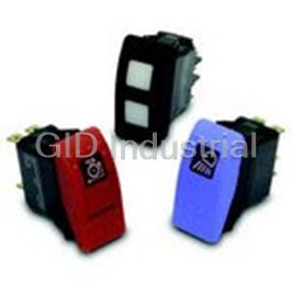
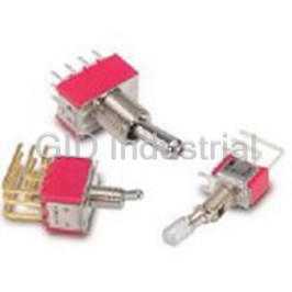
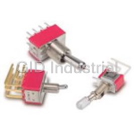
Rocker Actuators without Lenses
VVPZC00-000BLACK
Part Number
VVPZC00-000BLACK
Price
Request Quote
Manufacturer
CARLING TECHNOLOGIES
Lead Time
Request Quote
Category
Sensors and Transducers » Switch Accessories
Specifications
Manufacturer
Carling Technologies
Manufacturers Part #
VVPZC00-000BLACK
Industry Aliases
VVPZC00-000 BLACK
Sub-Categories
Switch Accessories
Factory Pack Quantity
1
Datasheet

Extracted Text
V-Series Switch Product Highlights: Maximum sealing protection with dual seals around lamps and rocker stem certified to IP66 & IP68. Optional panel seals for additional protection. Silver plated butt contact mechanism provides 50 to 100 thousand electrical cycles and a variety of different electrical ratings. Roller pin mechanism does not require lubricants and allows the switch to withstand extreme temperatures. The switch base accommodates up to 10 terminals and a large variety of switch and lighting circuits. The multi-step mounting wings provide a secure fit for CONTURA II CONTURA III panel thicknesses of 0.032” thru 0.250” in an industry standard 0.830” x 1.450” mounting hole. The switch connector allows the user to preload FQC terminals for easy assembly to switch base. Numerous choices of removable rockers allow for style CONTURA V change without having to retest or re-qualify the switch base. Illumination options are endless with bar, oval, and square lenses available in choices of incandescent, neon and Carling Technologies’ fully sealed V-Series Contura switches a wide variety of LEDs including superbrite, megabrite, are well known for their cutting edge design, high quality, flashing and bicolor lighting. maximum performance and unmatched reliability. These Available with a variety of complimentary mounting switches are a staple in the marine and transportation panels, hole plugs, illuminated indicators and boots to industries and have passed a range of environmental, accommodate most any design need. corrosion, temperature, vibration, shock and sealing tests including MIL Std 202F, MIL Std 810C, UL 1500, ISO 8846, IEC 60529 and BS 5490 among others, making them one of the most rugged and reliable switches ever manufactured. Carling Technologies, Inc. 60 Johnson Avenue • Plainville, CT 06062-1177 Phone: (860) 793-9281 • Fax: (860) 793-9231 Email: sales@carlingtech.com • www.carlingtech.com | 2 V-Series Contura Sealed Rocker Switches V-Series Switch DESIGN FEATURES MAXIMUM DESIGN OPTIONS WITH MINIMUM INVENTORIES Panel redesign is a snap, SEALS OUT WATER, DUST requiring no tooling change, with AND DEBRIS our removable interchangeable Dual seal protection locks actuators. A unique balance out elements. Certified to between aesthetics and IP66/IP68 for front panel functionality. components. CLEAN CONNECTIONS Offered in both eight and ten terminal base options. AMP & Packard compatible connectors available. SILVER PLATED BUTT Contact mechanism provides 50 to 100 thousand electrical cycles and a variety of different electrical ratings. WITHSTANDS EXTREME TEMPERATURES Roller pin mechanism eliminates the need for lubricants. Enables switch MULTIPLE LIGHTING OPTIONS to withstand -40°C to Incandescent lamps & LED lighting. Our +85°C temperatures. LED illumination is offered in a wide array of light intensities, colors, as well as dual OPTIONAL PANEL SEAL level, tri-color, and flashing options. Prevents water/dust egress behind panel. 60 Johnson Avenue • Plainville, CT 06062–1177 • Phone: (860) 793–9281 • Fax: (860) 793–9231 Email: sales@carlingtech.com • www.carlingtech.com | V-Series Contura Sealed Rocker Switches & Illuminated Plug 3 V-Series Contura Switches V-Series switches offer countless unique options including choices for ratings, colors, illuminations and symbols. These switches feature removable actuators in a choice of actuator styles and colors, and are available in single or double pole configurations. The V-Series switches can be illuminated with either square, oval and/or bar shaped lenses. Contura II Contura X The Contura II actuators are The raised bracket/bezel on constructed of thermoplastic the Contura X helps prevent polycarbonate, & are offered with inadvertent actuation of the either a hard nylon overlay, or a rocker, as well as preventing “soft-touch” elastomer overlay. debris from being trapped The Contura II incorporates an under the actuator. This curved aesthetic design of two rows rocker style is available with a of raised “bumps” on the top & variety of lenses and legends. bottom of the rocker. Contura III Contura XI The Contura III actuators are The raised bracket/bezel on constructed of thermoplastic the Contura XI helps prevent polycarbonate, & are offered inadvertent actuation of the with either a hard nylon or a rocker, as well as preventing “soft-touch” elastomer overlay. debris from being trapped under The Contura III incorporates the actuator. This convex style three rows of bars on the top & rocker is available with a wide bottom of the rocker. variety of lenses and legends. Contura IV Contura XII The Contura IV’s “Shape to The Contura XII version features create a Shape” actuator a paddle style actuator with the supports the designer, by raised bracket/bezel of Contura working with the curves, X and XI. The contoured handle contours & advanced styling of design provides intuitive the latest panel designs, flowing recognition and ease of with these advanced curves & operation and is available with radii. This actuator style fits on all Contura X and XI lens and the Contura flush bracket/bezel. legend offerings. Contura V Illuminated Indicator The symmetrically curved The Illuminated Indicator Contura V actuator provides is offered with removable/ the perfect complement to the replaceable lamps and Contura IV’s “Shape to create a Contura II, III, V, or X styling. Shape” design concept. With its Illumination alerts the operator flush style mounting bracket, of essential system functions or Contura V can be mounted in malfunctions like: oil pressure, between two Contura IV’s, by high temperature, fluid levels, itself, or in groups. parking brake, or general system malfunction. Contura VI (WAVE) The Contura VI WAVE sealed V–Series rocker switches, when used Accessories/Options in a row, create an uniquely Carling Technologies also offers appealing “wave” design on your many V-Series accessories panel. A variety of colors and including connectors, mounting finishes are available for both panels, hole plugs, panel seals, rocker and wave insert. Contura and actuator removal tools. VI features bar and oval lenses. 60 Johnson Avenue • Plainville, CT 06062–1177 • Phone: (860) 793–9281 • Fax: (860) 793–9231 60 Johnson Avenue • Plainville, CT 06062–1177 • Phone: (860) 793–9281 • Fax: (860) 793–9231 Email: sales@carlingtech.com • www.carlingtech.com Email: sales@carlingtech.com • www.carlingtech.com | 4 V–Series Contura Sealed Rocker Switches Electrical Agency Certifications Contact Rating 4VA @ 28VDC (MAX) resistive 15 amps, 125VAC 10 amps, 250VAC 1/2 HP 125-250VAC Environmental 20 amps, 4-14VDC Environmental Sealed version: IP68, in accordance 15 amps, 15-28VDC with IEC 60529, BS 5490, DIN 400 50 10A, 14VT & NFC 20 010. This rating applies to 6A, 125VAC L front panel components of the actual Dielectric Strength 1500 Volts RMS switch only, and signifies protection Insulation Resistance 50 Megohms against dust and the prolonged effects Initial Contact Resistance 10 milliohms max. @ 4VDC of immersion under pressure. The Life 50,000- 100,000 cycles circuit standard test for immersion under pressure requires submersion under dependent one meter of water for 30 minutes. The Contacts Silver alloy, silver tin-oxide, fine silver V-Series switch has exceeded these Terminals Brass or copper/silver plate 1/4” parameters, having been actuated (6.3mm) Quick Connect terminations and illuminated during submersion. standard. Solder lug, Wire Lead Corrosion Flowing Mixed Gas (FMG) Class III 3 year accelerated exposure Mechanical per ASTM B-827, B-845 Silver and gold contacts Endurance 150,000 cycles minimum Operating Temperature -40°C to + 85°C circuit dependent Vibration 1 Per Mil-Std 202F, Method 204D Test Condition A 0.06 DA or 10G’s 10-500 Physical Hz. Tested with VCH connector. Test Lighted Incandescent - rated 10,000 hours criteria - No loss of circuit during Neon - rated 25,000 hours test and pre and post test contact LED - rated 100,000 hours 1/2 life resistance. (LED is internally ballasted for Vibration 2 Resonance search 24-50 Hz 0.40 DA voltages to 24VDC) 50-2000 ±10 G’s peak Seals Internal Results Horizontal Axis 3-5 G’s max. Optional external gasket panel seal Random Base Polyester blend rated to 125°C with a 24 Hz 0.06 PSD-Gsq/Hz UL flammability rating of 94V0. 60 Hz 0.50 Contura II, III, IV, V, VI 100 Hz 0.50 Actuator Hard Surface: Basic actuator . 200 Hz 0.025 structure molded of thermoplastic 2000 Hz 0.025 Shock No loss of circuit during test; <10µ polycarbonate with a hard Nylon 66 seconds chatter. thermoplastic surface overlay. Per Mil-Std 202F, Method 213B, Test Soft Surface: Basic actuator structure Condition K @ 30G’s. Tested with VCH molded of thermoplastic connector. Test criteria - No loss of polycarbonate with an elastomer overlay. Salt Spray circuit during test, pre and post test Contura X, XI, XII contact resistance. Actuator, VP Nylon 66 Reinforced rated to 105°C Per Mil-Std 202F, Method 101D, Test Dust Condition A, 48 Hrs. Sealed version Lens Polycarbonate rated at 100°C only. Per Mil-Std 810C, Method 510.2 Air Actuator Travel (Angular Displacement) Thermal Shock Velocity 300 ±200 Feet/Min, Test 2 position 18° Duration 16 Hrs. 3 positions 9° from center Per Mil-Std 202F, Method 107F, Test Moisture Resistance Cond. A, -55°C to 85°C. Test criteria - pre and post test contact resistance Mounting Specifications .830[21.08] Per Mil-Std 202F, Method 106F, Test Panel Thickness Range Ignition Protection Criteria - pre and post test contact # of gaskets Acceptable Panel Thickness resistance 0 .030 to .250 (.76mm to 6.35mm) TEST CUT All Contura switches with sealed HOLE IN 1.450[36.83] 1 .030 to .109 & .147 to .157 ACTUAL construction meet the requirements MATERIAL of UL1500/ISO8846 for ignition (.76 to 2.77mm & 3.73 to 3.98mm) protection, in addition to conformance Recommended: No gasket with panel thickness of with EC directive 94/25/EC for marine .032, .062, .093, .125,.187 or .250 SWITCH products. MOUNTING HOLE 60 Johnson Avenue • Plainville, CT 06062–1177 • Phone: (860) 793–9281 • Fax: (860) 793–9231 Email: sales@carlingtech.com • www.carlingtech.com | V–Series Contura II, III, & IV 5 Dimensional Specifications: in. [mm] 60 Johnson Avenue • Plainville, CT 06062–1177 • Phone: (860) 793–9281 • Fax: (860) 793–9231 60 Johnson Avenue • Plainville, CT 06062–1177 • Phone: (860) 793–9281 • Fax: (860) 793–9231 Email: sales@carlingtech.com • www.carlingtech.com Email: sales@carlingtech.com • www.carlingtech.com | 6 V-Series Contura V & VI Dimensional Specifications: in. [mm] CONTURA VI CONTURA V CONTURA V SHOWN WITH OVAL SHOWN WITH SHOWN WITH LENS BAR LENS LOW PROFILE LOCK 1.950[49.53] 1.922[48.56] 1.922[48.56] .080[2.03] 1.079[27.40] 1.126 1.479[37.57] 1.550[39.37] 10 TERMINAL BASE 8 TERMINAL BASE 8 TERMINAL BASE W/BARRIER AND W/BARRIERS W/O BARRIERS LAMP TERMINAL 1.020[25.91] 1.020[25.91] 1.000[25.40] .505[12.83] .505[12.83] .250[6.35] .250[6.35] .250[6.35] X X X .031[.78] .031[.78] .031[.78] .390[9.90] .820[20.83] .820[20.83] .960[24.38] .960[24.38] .960[24.38] 8 TERMINAL BASE 8 TERMINAL BASE 10 TERMINAL BASE W/BARRIERS W/O BARRIERS W/O BARRIERS 8 7 8 7 1 4 1 4 2.029[51.53] 2 5 2 5 3 6 3 6 10 9 SWITCH SHOWN WITH BOTTOM VIEW BOTTOM VIEW VCH CONNECTOR 8 TERMINAL SWITCH SHOWN WITH TERMINAL TERMINAL ARRANGEMENT VC1 CONNECTOR 10 ARRANGEMENT 10 TERMINAL BASE TERMINAL 8 TERMINAL BASE 60 Johnson Avenue • Plainville, CT 06062–1177 • Phone: (860) 793–9281 • Fax: (860) 793–9231 Email: sales@carlingtech.com • www.carlingtech.com | V-Series Contura X, XI & XII 7 Dimensional Specifications: in. [mm] CONTURA X STYLE CONTURA XI STYLE CONTURA XII STYLE SHOWN WITH RAISED BRACKET SHOWN WITH RAISED SHOWN WITH PADDLE BRACKET AND TWO SQUARE ACTUATOR LENSES .667 [16.94] 1.910[48.51] .350[8.89] 1.910[48.51] .426[10.82] 1.305[33.15] .350[8.89] 1.586[40.28] 1.506[38.25] 1.370[34.79] 1.370[34.79] 1.370[34.79] 8 TERMINAL BASE 10 TERMINAL BASE 8 TERMINAL BASE W/BARRIERS W/O BARRIERS W/O BARRIERS .960[24.38] .960[24.38] .960[24.38] .780[19.81] .780[19.81] .780[19.81] .250[6.35] X .031[.78] .390[9.90] .390[9.90] .390[9.90] .820[20.82] .820[20.82] .820[20.82] 8 TERMINAL BASE 10 TERMINAL BASE 10 TERMINAL W/BARRIERS W/BARRIERS BASE W/O BARRIERS 8 7 8 7 1 4 1 4 2 5 2 5 3 6 36 10 9 BOTTOM VIEW BOTTOM VIEW SWITCH SHOWN WITH SWITCH SHOWN WITH TERMINAL TERMINAL VCH CONNECTOR VC1 CONNECTOR ARRANGEMENT ARRANGEMENT 8 TERMINAL 10 TERMINAL 8 TERMINAL BASE 10 TERMINAL BASE 60 Johnson Avenue • Plainville, CT 06062–1177 • Phone: (860) 793–9281 • Fax: (860) 793–9231 60 Johnson Avenue • Plainville, CT 06062–1177 • Phone: (860) 793–9281 • Fax: (860) 793–9231 Email: sales@carlingtech.com • www.carlingtech.com Email: sales@carlingtech.com • www.carlingtech.com | 8 V-Series Contura V & VI CIRCUIT CIRCUIT DIAGRAM CIRCUIT CIRCUIT DIAGRAM CIRCUIT CIRCUIT DIAGRAM 3 3 6 13 46 1 A J 2 25 25 3 3 6 1 3 4 6 2 B K 2 2 5 2 5 3 3 6 1 34 6 3 C L 2 2 5 2 5 1 3 1 3 4 6 3 6 4 D M 2 2 5 2 5 1 3 13 4 6 1 3 6 5 E R 2 25 2 5 13 1 3 4 6 13 6 6 F S 2 2 5 25 13 3 6 SYMBOL LEGEND 7 G SYM. DEFINITION DESIGNATES TERMINALS AND CONTACTS 2 2 5 DESIGNATES LAMP LOCATION 1 3 3 4 DESIGNATES MAINTAINED CIRCUITS DESIGNATES OTHER POSITION DESIGNATES MOMENTARY CIRCUITS 8 H DESIGNATES TWO POSITION CONNECTION DESIGNATES EXTERNAL JUMPER PROVIDED 2 25 BY CUSTOMER 60 Johnson Avenue • Plainville, CT 06062–1177 • Phone: (860) 793–9281 • Fax: (860) 793–9231 Email: sales@carlingtech.com • www.carlingtech.com | V-Series Contura X, XI & XII 9 LAMP LAMP LAMP LAMP CIRCUIT DIAGRAM CIRCUIT DIAGRAM CIRCUIT DIAGRAM CIRCUIT DIAGRAM CIRCUIT CIRCUIT CIRCUIT CIRCUIT +3 +6 +8 +8 +3 -6 +3 -6 SPECIAL 1 2 A/1 1 F/6 1 2 L/9 1 #1 -7 -7 -7 +8 +6 +3 +8 +3 +3 -6 SPECIAL B/2 1 G/7 12 M/R 2 1 2 #3 -7 -7 -7 +8 +3 +3 +8 +1 +3 -4 -6 SPECIAL 1 2 C/3 2 H/Z 2 N/T 1 2 #4 -7 -7 -7 +1 -8 +3 +6 +1 +3 -4 -6 +3 D/4 J/8 P/V 1 2 12 1 2 -7 -7 +8 +10 +1 +3 +8 +6 U/Y 12 E/5 K/W 1 2 12 -7 -9 -7 (-)7 CIRCUIT CIRCUIT DIAGRAM CIRCUIT CIRCUIT DIAGRAM CIRCUIT CIRCUIT DIAGRAM CIRCUIT CIRCUIT CIRCUIT CIRCUIT DIAGRAM CIRCUIT DIAGRAM CIRCUIT DIAGRAM 13 17 18 10(-) 10(-) 1 3 17 18 11 11 11 11 13 13 13 13 31 3 3 3 14 14 14 4 6 NOTE: 1 3 17 18 10(-) 13 13 11 3 3 3 31 14 14 14 4 10(-) 17 18 6 J circuits are available for all non-locking V-Series J1 J5 JA 1 2 styles. Consult factory for J1 J5 JA 1 2 p/n details. 2 2 5 58 8 2 5 8 5 2 28 5 5 8 2 58 5 11 11 11 11 13 13 13 13 3 3 3 3 14 17 18 10(-) 11 13 3 3 3 3 14 11 11 11 11 13 13 13 13 3 3 3 3 14 17 18 10(-) 1311 3 3 3 3 14 J2 JJ 1 J2 JJ 1 58 5 8 13 17 18 10(-) 11 13 3 3 3 3 14 12 616 15 1 3 17 18 10(-) 1311 3 3 3 314 15 12 6 16 J3 JK 1 J3 JK 1 2 5 8 25 8 13 17 18 10(-) 1 3 17 18 10(-) SYMBOL LEGEND SYMBOL LEGEND CIRCUIT CONNECTOR PART # SYM. DEFINITION J4 1 J4 1 SYM. DEFINITION JA,JJ,JK JC1-01 DESIGNATES TERMINALS AND CONTACTS J1,J3,J4,J5 JC2-01 DESIGNATES TERMINALS AND CONTACTS DESIGNATES TERMINALS AND CONTACTS DESIGNATES LAMP LOCATION DESIGNATES LAMP LOCATION DESIGNATES LAMP LOCATION J2 JC3-01 2 5 5 2 DESIGNATES TWO POSITION CIRCUI DESIGNATES TWO POSITION CIRCUIT T 60 Johnson Avenue • Plainville, CT 06062–1177 • Phone: (860) 793–9281 • Fax: (860) 793–9231 60 Johnson Avenue • Plainville, CT 06062–1177 • Phone: (860) 793–9281 • Fax: (860) 793–9231 Email: sales@carlingtech.com • www.carlingtech.com Email: sales@carlingtech.com • www.carlingtech.com | 10 V-Series Contura II & III Sealed Rocker Switches V 1 D A B T 0 B — A R B 00 — 0 00 1 2 3 4 5 6 7 8 9 10 11 12 13 14 Bracket Actuator Lens Color Legend Legend Actuator Series Circuit Rating Termination Illumination Lamp Lamp Orientation Lens Legend 1 SERIES 6,7 LAMP (SAME CODING FOR BOTH SELECTIONS) Selection 6: above terminals 1 & 4; Selection 7: above terminals 3 & 6 V No lamp 0 Neon 1 125VAC 2 250VAC Incandescent 4 3V 5 6V 6 12V 7 18V 8 24V 2 CIRCUIT LED* superbright superbright Terminal Connections as viewed ( ) - momentary Red Amber Green Red from bottom of switch: 2VDC A L F R 8 terminal 10 terminal SP - single pole - uses terminals 1, 2 & 3. 8 - - 7 8 - - 7 DP - double pole uses terminals 1, 2, 3, 4, 5 & 6. 6VDC B M G S 1 - - 4 1 - - 4 12VDC C N H T Terminals 7, 8, 9 & 10 for lamp circuit only. 2 - - 5 2 - - 5 24VDC D P J V 3 - - 6 3 - - 6 * Consult factory for “daylight bright” LED options. Typical current draw for LED is 20ma. 10 - - 9 Position: 1 2 3 SP DP 2 & 3, 5 & 6 Connected Terminals 1 & 2, 4 & 5 1 1 A ON NONE OFF 8 FLUSH BRACKET COLOR , PANEL SEAL 2 B (ON) NONE OFF Black White Gray 3 C ON NONE (OFF) No Seal B W G 4 D ON NONE ON One Seal C Y H 5 F ON NONE (ON) 6 J ON OFF ON 7 K ON OFF (ON) 9 ACTUATOR 8 L (ON) OFF (ON) SPECIAL CIRCUITS No Actuator 0 H* 2 & 3 2 & 3, 5 & 4 5 & 4 Contura II A G* 2 & 3, 5 & 6 2 & 3 OFF B S 2 & 3, 5 & 6 2 & 3 1 & 2 Contura III C M* (2 & 3, 5 & 6) 2 & 3 OFF D R (2 & 3, 5 & 6) 2 & 3 1 & 2 3,6 1,4 Actuator orientation above terminals: E* 5 & 6 5 & 3 5 & 1 *Jumper between terminals 2 & 5 for circuits H, G, & M are specified in selection 4. External jumper between terminals 2 & 4 for circuit E are provided by customer. Circuit E 10 LENS may be used for SP OFF-ON-ON circuit. 0 - No Actuator Z - No Lens Clear White Amber Green Red Blue 3 1 6 B G M T 3 RATING 2 7 C H N U 1 .4VA @ 28VDC Resistive 3 8 D J P V B 15A 24V Square lens options available only for Contura II: C 20A 18V 4 9 E K R W D 20A 12V E 20A 14V, 10A 14VT (circuit 1, 4 , A & D only) 5 A F L S Y Lens color for LEDs must be clear, white, or match color of LED. F 10A 14V, 6A 14VT (circuit 6 only) M .4VA/20A 12V Green or blue lenses are not recommended with Neon lamps. N .4VA/15A 24V 1 11 ACTUATOR COLOR AND TEXTURE 4 TERMINATION/BASE STYLE 0 - No Actuator 8 term 10 term Termination Jumper Black Gray Red White 1 2 .250 TAB (QC) no barriers No Soft Surface B G R W A B .250 TAB (QC) with barriers No Hard Surface C H S Y J K .250 TAB (QC) no barriers Yes T2 to 5 3 4 Solder Lug no barriers No C D Solder Lug No 2 12 ACTUATOR LENS OR BODY LEGENDS 5 6 Wire Leads no barriers No 11 ON 12 OFF 13 | 14 O E F Wire Leads No OFF ON O | Note: Codes J & K for circuits H, G & M. 15 O O 16 O O 17 O | 18 |O F N F N 5 ILLUMINATION & SWITCH SEALING F F Lamp #1:above terminals 1 & 4 end of switch.; Lamp #2 above terminals 3 & 6 end of For additional legend options & codes, see pages 54-65 of the Carling Transportation catalog switch. Positive (+) and negative (-) symbols apply to LED lamps only Actuator Lens position Lamp wired to ORIENTATION OF ACTUATOR/LENS IN PANEL Sealed Unsealed Lamps when Illuminated Terminals ORIENTATION 1 13 LEGEND ORIENTATION S 0 NONE 0 No legend (used with codes 11-18 in selection 12) A 1 # 1 Independent 8+ 7- 1 Orientation 1 B 2 # 1 Down 3+ 7- C 3 # 2 Up 3+ 7- 2 Orientation 2 D 4 # 1 Down 3+ 7- 3 Orientation 3 ORIENTATION 4 ORIENTATION 2 &# 2 Down 1+ 7- 4 Orientation 4 ARCMC-100 A9CE3-1E5 E 5 # 1 Up 1+ 7- A9C45-200 &# 2 Up 3+ 7- E3 MC F 6 # 1 Independent 8+ 7- AC E5 SLEEPER LIGHTS &# 2 Up 3+ 6- 45 G 7 # 1 Independent 8+ 7- AZCAC-100 ORIENTATION 3 &# 2 Up 3+ 7- H Z # 2 Independent 8+ 7- U Y # 1 Independent 8+ 7- 14 ACTUATOR LENS LEGEND &# 2 Independent 10+ 9- 00 No legend this location / no actuator Selections for Single Pole Switches Only: (used with codes 11-18 in selection 12) Selection 14 required when switch requires two J 8 # 1 Down 3+ 8- legends. If the two legends consist of one lens and one body legend, lens legend must be &# 2 Independent 6+ 7- specified in selection 12; body legend specified in selection 14. K W # 1 Independent 8+ 7- For legend options & codes, see pages 54-65 of the Carling Transportation catalog &# 2 Independent 6+ 7- Selections for Double Pole Switches Only: Notes: L 9 #1 Down 3+ 6- Consult factory to verify horsepower rating for your particular circuit choice. M R # 2 Up 3+ 6- 1 Custom colors are available. Consult factory. N T # 1 Down 3+ 6- 2 Body legends not available on Soft surface actuators; White imprinting is standard on &# 2 Down 1+ 4- black actuators; Black imprinting is standard on white, red and gray actuators; Custom P V # 1 Up 1+ 4- &# 2 Up 3+ 6- colors are available, consult factory. 3 Additional ratings available. See page 19. 4 Contura II available with two square lenses. Consult factory for details. 60 Johnson Avenue • Plainville, CT 06062–1177 • Phone: (860) 793–9281 • Fax: (860) 793–9231 Email: sales@carlingtech.com • www.carlingtech.com | V-Series Contura II & III Locking Sealed Rocker Switches 11 V 1 D A S W 0 B — A Z E 00 — 0 1 2 3 4 5 6 7 8 9 10 11 12 13 Bracket Actuator Lens Function Legend Legend Series Circuit Rating Termination Illumination Lock Lamp Orientation 1 SERIES 7 LAMP Lamp above terminals 3 & 6 end of switch V No lamp 0 Neon 1 125VAC 2 250VAC Incandescent 4 3V 5 6V 6 12V 7 18V 8 24V 2 CIRCUIT LED* superbright superbright Terminal Connections as viewed ( ) - momentary Red Amber Green Red from bottom of switch: 2VDC A L F R 8 terminal 10 terminal SP - single pole - uses terminals 1, 2 & 3. 8 - - 7 8 - - 7 DP - double pole uses terminals 1, 2, 3, 4, 5 & 6. 6VDC B M G S 1 - - 4 1 - - 4 12VDC C N H T Terminals 7, 8, 9 & 10 for lamp circuit only. 2 - - 5 2 - - 5 24VDC D P J V 3 - - 6 3 - - 6 * Consult factory for “daylight bright” LED options. Typical current draw for LED is 20ma. 10 - - 9 Position: 1 2 3 SP DP 2 & 3, 5 & 6 Connected Terminals 1 & 2, 4 & 5 1 1 A ON NONE OFF 8 FLUSH BRACKET COLOR , PANEL SEAL 2 B (ON) NONE OFF Black White Gray 3 C ON NONE (OFF) No Seal B W G 4 D ON NONE ON One Seal C Y H 5 F ON NONE (ON) 6 J ON OFF ON 7 K ON OFF (ON) 1 9 HARD SURFACE ACTUATOR 8 L (ON) OFF (ON) SPECIAL CIRCUITS Black Grey Red White H* 2 & 3 2 & 3, 5 & 4 5 & 4 Contura II A B G H G* 2 & 3, 5 & 6 2 & 3 OFF S 2 & 3, 5 & 6 2 & 3 1 & 2 Contura III C D E F M* (2 & 3, 5 & 6) 2 & 3 OFF R (2 & 3, 5 & 6) 2 & 3 1 & 2 3,6 1,4 Actuator orientation above terminals: E* 5 & 6 5 & 3 5 & 1 *Jumper between terminals 2 & 5 for circuits H, G, & M are specified in selection 4. External jumper between terminals 2 & 4 for circuit E are provided by customer. Circuit E 10 LENS may be used for SP OFF-ON-ON circuit. Z - No Lens Clear White Amber Green Red Blue 14 3 8 D J P V 3 RATING Lens color for LEDs must be clear, white, or match color of LED. 1 .4VA @ 28VDC Resistive Green or blue lenses are not recommended with Neon lamps. B 15A 24V C 20A 18V D 20A 12V 1 E 20A 14V, 10A 14VT (circuit 1, 4 , A & D only) 11 ACTUATOR LOCK FUNCTION AND COLOR 3 F 10A 14V, 6A 14VT (circuit 6 only) Lock Color Up Down Up & Down Center M .4VA/20A 12V Match Actuator A H R 1 N .4VA/15A 24V Black B J S 2 White C K T 3 Red D L V 4 4 TERMINATION/BASE STYLE Safety Orange E M W 5 8 term 10 term Termination Jumper 1 2 .250 TAB (QC) no barriers No A B .250 TAB (QC) with barriers No 2 12 ACTUATOR LENS OR BODY LEGEND J K .250 TAB (QC) no barriers Yes T2 to 5 00 - No Legend 3 4 Solder Lug no barriers No 21 22 23 24 C D Solder Lug No OFF ON O I 5 6 Wire Leads no barriers No E F Wire Leads No 25 O 26 O 27 O 28 I Note: Codes J & K for circuits H, G & M. F N F For additional legend options & codes, see pages 54-65 of the Carling Transportation catalog 5 ILLUMINATION & SWITCH SEALING Lamp #1:above terminals 1 & 4 end of switch.; Lamp #2 above terminals 3 & 6 end of ORIENTATION OF ACTUATOR/LENS IN PANEL switch. Positive (+) and negative (-) symbols apply to LED lamps only ORIENTATION 1 13 LEGEND ORIENTATION Actuator Lens position Lamp wired to 0 No legend (used with codes 21-28 in selection 12) Sealed Unsealed Lamps when Illuminated Terminals 1 Orientation 1 S 0 NONE 2 Orientation 2 C 3 # 2 Up 3+ 7- 3 Orientation 3 H Z # 2 Independent 8+ 7- ORIENTATION 4 ORIENTATION 2 Selections for Double Pole Switches Only: 4 Orientation 4 AZC45-1 M R # 2 Up 3+ 6- AZC45-2 45 6 LOCK 45 ORIENTATION 3 Lock above terminals 1 & 4 end of switch. W lock Notes: Consult factory to verify horsepower rating for your particular circuit choice. 1 Custom colors are available. Consult factory. 2 White imprinting is standard on black actuators; Black imprinting is standard on white, red and gray actuators; Custom colors are available, consult factory. 3 Only available with 3 position circuits. Center OFF and special circuits only available with center position lock function. 4 Additional ratings available. See page 19. 60 Johnson Avenue • Plainville, CT 06062–1177 • Phone: (860) 793–9281 • Fax: (860) 793–9231 60 Johnson Avenue • Plainville, CT 06062–1177 • Phone: (860) 793–9281 • Fax: (860) 793–9231 Email: sales@carlingtech.com • www.carlingtech.com Email: sales@carlingtech.com • www.carlingtech.com | 12 V-Series Contura IV Sealed Rocker Switches V 1 D A B T 0 B — E R C 00 — 0 00 1 2 3 4 5 6 7 8 9 10 11 12 13 14 Bracket Actuator Lens Color Legend Legend Actuator Series Circuit Rating Termination Illumination Lamp Lamp Orientation Lens Legend 1 SERIES 6,7 LAMP (same coding for both selections) Selection 6: above terminals 1 & 4; Selection 7: above terminals 3 & 6 V No lamp 0 Neon 1 125VAC 2 250VAC Incandescent 4 3V 5 6V 6 12V 7 18V 8 24V 2 CIRCUIT LED* superbright superbright Terminal Connections as viewed ( ) - momentary Red Amber Green Red from bottom of switch: 2VDC A L F R 8 terminal 10 terminal SP - single pole - uses terminals 1, 2 & 3. 8 - - 7 8 - - 7 DP - double pole uses terminals 1, 2, 3, 4, 5 & 6. 6VDC B M G S 1 - - 4 1 - - 4 12VDC C N H T Terminals 7, 8, 9 & 10 for lamp circuit only. 2 - - 5 2 - - 5 24VDC D P J V 3 - - 6 3 - - 6 * Consult factory for “daylight bright” LED options. Typical current draw for LED is 20ma. 10 - - 9 Position: 1 2 3 SP DP 2 & 3, 5 & 6 Connected Terminals 1 & 2, 4 & 5 1 1 A ON NONE OFF 8 FLUSH BRACKET COLOR , PANEL SEAL 2 B (ON) NONE OFF Black White Gray 3 C ON NONE (OFF) No Seal B W G 4 D ON NONE ON One Seal C Y H 5 F ON NONE (ON) 6 J ON OFF ON 7 K ON OFF (ON) 9 ACTUATOR 8 L (ON) OFF (ON) 1,4 SPECIAL CIRCUITS No Actuator 0 H* 2 & 3 2 & 3, 5 & 4 5 & 4 Contura IV, left orientation E G* 2 & 3, 5 & 6 2 & 3 OFF Contura IV, left orientation, laser etched T S 2 & 3, 5 & 6 2 & 3 1 & 2 Contura IV, right orientation F M* (2 & 3, 5 & 6) 2 & 3 OFF Contura IV, right orientation, laser etched R R (2 & 3, 5 & 6) 2 & 3 1 & 2 3,6 Actuator orientation above terminals: E* 5 & 6 5 & 3 5 & 1 *Jumper between terminals 2 & 5 for circuits H, G, & M are specified in selection 4. External jumper between terminals 2 & 4 for circuit E are provided by customer. Circuit E 10 LENS may be used for SP OFF-ON-ON circuit. 0 - No Actuator Z - No Lens Clear White Amber Green Red Blue 4 1 6 B G M T 3 RATING 2 1 .4VA @ 28VDC Resistive 7 C H N U B 15A 24V 3 8 D J P V C 20A 18V 4 9 E K R W D 20A 12V 5 A F L S Y E 20A 14V, 10A 14VT (circuit 1, 4 , A & D only) Lens color for LEDs must be clear, white, or match color of LED. F 10A 14V, 6A 14VT (circuit 6 only) Green or blue lenses are not recommended with Neon lamps. E F M .4VA/20A 12V N .4VA/15A 24V 1,5,6 11 ACTUATOR COLOR No Actuator 0 Black C Gray H Red S White Y Nickel D Pewter E 4 TERMINATION/BASE STYLE 8 term 10 term Termination Jumper 1 2 .250 TAB (QC) no barriers No 2 A B .250 TAB (QC) with barriers No 12 ACTUATOR LENS OR BODY LEGENDS J K .250 TAB (QC) no barriers Yes T2 to 5 11 ON 12 OFF 13 | 14 O 3 4 Solder Lug no barriers No OFF ON O | C D Solder Lug No 5 6 Wire Leads no barriers No 15 O O 16 O O 17 O | 18 |O E F Wire Leads No F N F N Note: Codes J & K for circuits H, G & M. F F For additional legend options & codes, see pages 54-65 of the Carling Transportation catalog 5 ILLUMINATION & SWITCH SEALING ORIENTATION OF ACTUATOR/LENS IN PANEL Lamp #1:above terminals 1 & 4 end of switch.; Lamp #2 above terminals 3 & 6 end of 13 LEGEND ORIENTATION ORIENTATION 1 switch. Positive (+) and negative (-) symbols apply to LED lamps only 0 No legend (used with codes 11-18 in selection 12) Actuator Lens position Lamp wired to 1 Orientation 1 Sealed Unsealed Lamps when Illuminated Terminals 2 Orientation 2 S 0 NONE 3 Orientation 3 A 1 # 1 Independent 8+ 7- 4 Orientation 4 ORIENTATION 4 ORIENTATION ORIENTATION 2 2 B 2 # 1 Down 3+ 7- E8C45-100 E3C70-200 E8C45-300 C 3 # 2 Up 3+ 7- D 4 # 1 Down 3+ 7- &# 2 Down 1+ 7- E 5 # 1 Up 1+ 7- &# 2 Up 3+ 7- F3C70-200 F8C45-300 F8C45-100 ORIENTATION 3 F 6 # 1 Independent 8+ 7- &# 2 Up 3+ 6- G 7 # 1 Independent 8+ 7- &# 2 Up 3+ 7- 14 ACTUATOR LENS LEGEND H Z # 2 Independent 8+ 7- 00 No legend this location / no actuator U Y # 1 Independent 8+ 7- (used with codes 11-18 in selection 12) Selection 14 required when switch requires two &# 2 Independent 10+ 9- legends. If the two legends consist of one lens and one body legend, lens legend must be Selections for Single Pole Switches Only: specified in selection 12; body legend specified in selection 14. J 8 # 1 Down 3+ 8- For legend options & codes, see pages 54-65 of the Carling Transportation catalog &# 2 Independent 6+ 7- K W # 1 Independent 8+ 7- Notes: &# 2 Independent 6+ 7- Consult factory to verify horsepower rating for your particular circuit choice. Selections for Double Pole Switches Only: 1 Custom colors are available. Consult factory. L 9 #1 Down 3+ 6- 2 White imprinting is standard on black actuators; Black imprinting is standard on white, M R # 2 Up 3+ 6- red and gray actuators; Custom colors are available, consult factory. N T # 1 Down 3+ 6- 3 Gloss brow is on left side of E actuator and right side of F actuator. &# 2 Down 1+ 4- 4 Additional ratings available. See page 19. P V # 1 Up 1+ 4- 5 Laser etched rocker only available with lens code Z & actuator colors black, nickel or &# 2 Up 3+ 6- pewter. 6 Pewter and nickel colors only available with laser etched actuator. 60 Johnson Avenue • Plainville, CT 06062–1177 • Phone: (860) 793–9281 • Fax: (860) 793–9231 Email: sales@carlingtech.com • www.carlingtech.com | V-Series Contura V Sealed Rocker Switches 13 V 1 D A B T 0 B — G R C 00 — 0 00 1 2 3 4 5 6 7 8 9 10 11 12 13 14 Bracket Actuator Lens Color Legend Legend Actuator Series Circuit Rating Termination Illumination Lamp Lamp Orientation Lens Legend 1 SERIES 6,7 LAMP (same coding for both selections) Selection 6: above terminals 1 & 4; Selection 7: above terminals 3 & 6 V No lamp 0 Neon 1 125VAC 2 250VAC Incandescent 4 3V 5 6V 6 12V 7 18V 8 24V 2 CIRCUIT LED* superbright superbright Terminal Connections as viewed ( ) - momentary Red Amber Green Red from bottom of switch: 2VDC A L F R 8 terminal 10 terminal SP - single pole - uses terminals 1, 2 & 3. 8 - - 7 8 - - 7 DP - double pole uses terminals 1, 2, 3, 4, 5 & 6. 6VDC B M G S 1 - - 4 1 - - 4 12VDC C N H T Terminals 7, 8, 9 & 10 for lamp circuit only. 2 - - 5 2 - - 5 24VDC D P J V 3 - - 6 3 - - 6 * Consult factory for “daylight bright” LED options. Typical current draw for LED is 20ma. 10 - - 9 Position: 1 2 3 SP DP 2 & 3, 5 & 6 Connected Terminals 1 & 2, 4 & 5 1 1 A ON NONE OFF 8 FLUSH BRACKET COLOR , PANEL SEAL 2 B (ON) NONE OFF Black White Gray 3 C ON NONE (OFF) No Seal B W G 4 D ON NONE ON One Seal C Y H 5 F ON NONE (ON) 6 J ON OFF ON 7 K ON OFF (ON) 9 ACTUATOR 8 L (ON) OFF (ON) SPECIAL CIRCUITS No Actuator 0 H* 2 & 3 2 & 3, 5 & 4 5 & 4 Contura V G G* 2 & 3, 5 & 6 2 & 3 OFF Contura V, laser etched P S 2 & 3, 5 & 6 2 & 3 1 & 2 M* (2 & 3, 5 & 6) 2 & 3 OFF R (2 & 3, 5 & 6) 2 & 3 1 & 2 E* 5 & 6 5 & 3 5 & 1 10 LENS Lens style & *Jumper between terminals 2 & 5 for circuits H, G, & M are specified in selection 4. Lens color for LEDs must be clear, white, or match color of LED. location: External jumper between terminals 2 & 4 for circuit E are provided by customer. Circuit E Green or blue lenses are not recommended with Neon lamps. #1/ #2 may be used for SP OFF-ON-ON circuit. 0 - No Actuator Z - No Lens Clear White Amber Green Red Blue 1 6 B G M T bar 14 3 RATING 2 7 C H N U bar/bar 1 .4VA @ 28VDC Resistive 3 8 D J P V oval B 15A 24V 4 9 E K R W oval/bar C 20A 18V D 20A 12V 5 A F L S Y oval/oval E 20A 14V, 10A 14VT (circuit 1, 4 , A & D only) F 10A 14V, 6A 14VT (circuit 6 only) M .4VA/20A 12V 1,3,3 11 ACTUATOR COLOR N .4VA/15A 24V No Actuator 0 Black C Gray H Red S White Y Nickel D Pewter E 4 TERMINATION/BASE STYLE 2,6 12 ACTUATOR LENS OR BODY LEGENDS 8 term 10 term Termination Jumper 11 ON 12 OFF 13 | 14 O 1 2 .250 TAB (QC) no barriers No A B .250 TAB (QC) with barriers No OFF ON O | J K .250 TAB (QC) no barriers Yes T2 to 5 15 O O 16 O O 17 O | 18 |O 3 4 Solder Lug no barriers No F N F N C D Solder Lug No F F 5 6 Wire Leads no barriers No For additional legend options & codes, see pages 54-65 of the Carling Transportation catalog E F Wire Leads No Note: Codes J & K for circuits H, G & M. ORIENTATION OF ACTUATOR/LENS IN PANEL 13 LEGEND ORIENTATION ORIENTATION 1 5 ILLUMINATION & SWITCH SEALING 0 No legend (used with codes 11-18 in selection 12) Lamp #1:above terminals 1 & 4 end of switch.; Lamp #2 above terminals 3 & 6 end of 1 Orientation 1 switch. Positive (+) and negative (-) symbols apply to LED lamps only 2 Orientation 2 Actuator Lens position Lamp wired to 3 Orientation 3 Sealed Unsealed Lamps when Illuminated Terminals 4 Orientation 4 S 0 NONE 4G13L 4G ORIENTATION 4 ORIENTATION 2 A 1 # 1 Independent 8+ 7- MC MA 4G B 2 # 1 Down 3+ 7- C 3 # 2 Up 3+ 7- MA MC 3L 4G200 D 4 # 1 Down 3+ 7- MA3MC MA1MC ORIENTATION 3 &# 2 Down 1+ 7- E 5 # 1 Up 1+ 7- &# 2 Up 3+ 7- F 6 # 1 Independent 8+ 7- 14 ACTUATOR LENS LEGEND &# 2 Up 3+ 6- 00 No legend this location / no actuator G 7 # 1 Independent 8+ 7- (used with codes 11-18 in selection 12) Selection 14 required when switch requires two &# 2 Up 3+ 7- legends. If the two legends consist of one lens and one body legend, lens legend must be H Z # 2 Independent 8+ 7- specified in selection 12; body legend specified in selection 14. U Y # 1 Independent 8+ 7- For legend options & codes, see pages 54-65 of the Carling Transportation catalog &# 2 Independent 10+ 9- Selections for Single Pole Switches Only: Notes: J 8 # 1 Down 3+ 8- Consult factory to verify horsepower rating for your particular circuit choice. &# 2 Independent 6+ 7- K W # 1 Independent 8+ 7- 1 Custom colors are available. Consult factory. &# 2 Independent 6+ 7- 2 White imprinting is standard on black actuators; Black imprinting is standard on white, Selections for Double Pole Switches Only: red and gray actuators; Custom colors are available, consult factory. L 9 #1 Down 3+ 6- 3 Laser Etched rocker only available with lens code Z & actuator colors black, nickel or pewter. M R # 2 Up 3+ 6- 4 Additional ratings available. See page 19. N T # 1 Down 3+ 6- 5 Nickel and Pewter colors only available with laser etched actuator. &# 2 Down 1+ 4- 6 Consult factory for laser etched lens callout. P V # 1 Up 1+ 4- &# 2 Up 3+ 6- 60 Johnson Avenue • Plainville, CT 06062–1177 • Phone: (860) 793–9281 • Fax: (860) 793–9231 60 Johnson Avenue • Plainville, CT 06062–1177 • Phone: (860) 793–9281 • Fax: (860) 793–9231 Email: sales@carlingtech.com • www.carlingtech.com Email: sales@carlingtech.com • www.carlingtech.com | 14 V-Series Contura IV & V Locking Sealed Rocker Switches V 1 D A S W 0 B — J Z E 00 — 0 1 2 3 4 5 6 7 8 9 10 11 12 13 Bracket Actuator Lens Function Legend Legend Series Circuit Rating Termination Illumination Lock Lamp Orientation 1 SERIES 7 LAMP Lamp above terminals 3 & 6 end of switch V No lamp 0 Neon 1 125VAC 2 250VAC 3 Incandescent 4 3V 5 6V 6 12V 7 18V 8 24V 2 CIRCUIT LED* superbright superbright Terminal Connections as viewed ( ) - momentary Red Amber Green Red from bottom of switch: 2VDC A L F R 8 terminal 10 terminal SP - single pole - uses terminals 1, 2 & 3. 8 - - 7 8 - - 7 DP - double pole uses terminals 1, 2, 3, 4, 5 & 6. 6VDC B M G S 1 - - 4 1 - - 4 Terminals 7& 8 for lamp circuit only. 12VDC C N H T 2 - - 5 2 - - 5 Terminals 9 & 10 are not used with locking style 24VDC D P J V 3 - - 6 3 - - 6 switches. 10 - - 9 Position: 1 2 3 1 8 FLUSH BRACKET COLOR , PANEL SEAL SP DP 2 & 3, 5 & 6 Connected Terminals 1 & 2, 4 & 5 Black White Gray 1 A ON NONE OFF No Seal B W G 4 D ON NONE ON 6 J ON OFF ON One Seal C Y H 7 K ON OFF (ON) 8 L (ON) OFF (ON) 9 N OFF NONE ON 9 HARD SURFACE ACTUATOR CONTURA IV: Orientation Black Grey Red White 4 Left J K L M 3 RATING 1 .4VA @ 28VDC Resistive Right N P R S B 15A 24V C 20A 18V Actuator orientation above terminals: 3,6 1,4 D 20A 12V CONTURA V: Black Grey Red White E 20A 14V, 10A 14VT (circuit 1, 4 , A & D only) U V W Y F 10A 14V, 6A 14VT (circuit 6 only) M .4VA/20A 12V Actuator orientation above terminals: 3,6 1,4 N .4VA/15A 24V 5 4 TERMINATION/BASE STYLE 10 LENS Z - No Lens 8 term 10 term Termination Jumper White Amber Green Red Blue Clear 1 2 .250 TAB (QC) no barriers No B C D E F bar lens A B .250 TAB (QC) with barriers No A H J K L M oval lens J K .250 TAB (QC) no barriers Yes T2 to 5 G 3 4 Solder Lug no barriers No Lens color for LEDs must be clear, white, or match color of LED. C D Solder Lug No Green or blue lenses are not recommended with Neon lamps. 5 6 Wire Leads no barriers No E F Wire Leads No 1 Note: Codes J & K for circuits H, G & M. 11 ACTUATOR LOCK FUNCTION AND COLOR 3 Lock Color Up Down Up & Down Center Match Actuator A H R 1 5 ILLUMINATION & SWITCH SEALING Black B J S 2 Lamp #1:above terminals 1 & 4 end of switch.; Lamp #2 above terminals 3 & 6 end of White C K T 3 switch. Positive (+) and negative (-) symbols apply to LED lamps only Red D L V 4 Actuator Lens position Lamp wired to Safety Orange E M W 5 Sealed Unsealed Lamps when Illuminated Terminals Gray F G N 6 S 0 NONE C 3 # 2 Up 3+ 7- H Z # 2 Independent 8+ 7- 2 Selections for Double Pole Switches Only: 12 ACTUATOR LENS OR BODY LEGEND M R # 2 Up 3+ 6- 00 - No Legend 21 22 23 24 OFF ON O I 6 LOCK Lock above terminals 1 & 4 end of switch. 25 O 26 O 27 O 28 I 6 W low profile lock Y high profile lock F N F For additional legend options & codes, see pages 54-65 of the Carling Transportation catalog Notes: Consult factory to verify horsepower rating for your particular circuit choice. ORIENTATION OF 1 Custom colors are available. Consult factory. ACTUATOR/LENS IN PANEL ORIENTATION 1 13 LEGEND ORIENTATION 2 White imprinting is standard on black actuators; Black imprinting is standard on white, red and gray actuators; Custom colors are available, consult factory. 0 No legend 1 Orientation 1 3 Only available with 3 position circuits. Center OFF and special circuits only available with center position lock function. 2 Orientation 2 4 Additional ratings available. See page 19. 3 Orientation 3 5 Located at T3-6 end of switch. 4 Orientation 4 6 Contura V style only. JHAY3-100 JHAY3-200 JHAY3-300 P P P P P P NHAY3-100 NHAY3-200 ORIENTATION 3 NHAY3-300 60 Johnson Avenue • Plainville, CT 06062–1177 • Phone: (860) 793–9281 • Fax: (860) 793–9231 Email: sales@carlingtech.com • www.carlingtech.com ORIENTATION 4 ORIENTATION 2 2 Orientation | V-Series Contura VI WAVE Sealed Rocker Switches 15 V 1 D B G N T B – H A 7 C B AC – 1 00 1 2 3 4 5 6 7 8 9 10 11 12 13 14 15 16 Series Circuit Rating Termination Illumination Lamp Lamp Bracket Actuator Lens Lens Color Insert Actuator Legend Actuator Color Lens Orientation Lens Legend 1 SERIES 6,7 LAMP (same coding for both selections) Selection 6: above terminals 1 & 4; Selection 7: above terminals 3 & 6 V No lamp 0 Neon 1 125VAC 2 250VAC Incandescent 4 3V 5 6V 6 12V 7 18V 8 24V 2 CIRCUIT LED* superbright superbright Terminal Connections as viewed ( ) - momentary Red Amber Green Red from bottom of switch: 2VDC A L F R 8 terminal 10 terminal SP - single pole - uses terminals 1, 2 & 3. 8 - - 7 8 - - 7 DP - double pole uses terminals 1, 2, 3, 4, 5 & 6. 6VDC B M G S 1 - - 4 1 - - 4 12VDC C N H T Terminals 7, 8, 9 & 10 for lamp circuit only. 2 - - 5 2 - - 5 24VDC D P J V 3 - - 6 3 - - 6 * Consult factory for “daylight bright” LED options. Typical current draw for LED is 20ma. 10 - - 9 Position: 1 2 3 SP DP 2 & 3, 5 & 6 Connected Terminals 1 & 2, 4 & 5 1 1 A ON NONE OFF 8 FLUSH BRACKET COLOR , PANEL SEAL 2 B (ON) NONE OFF Black White Gray 3 C ON NONE (OFF) No Seal B W G 4 D ON NONE ON One Seal C Y H 5 F ON NONE (ON) 6 J ON OFF ON 7 K ON OFF (ON) 9 ACTUATOR 8 L (ON) OFF (ON) SPECIAL CIRCUITS 0 No Actuator H High Insert L Low Insert H* 2 & 3 2 & 3, 5 & 4 5 & 4 G* 2 & 3, 5 & 6 2 & 3 OFF S 2 & 3, 5 & 6 2 & 3 1 & 2 4 M* (2 & 3, 5 & 6) 2 & 3 OFF 10,11 LENS R (2 & 3, 5 & 6) 2 & 3 1 & 2 Lens color for LEDs must be clear, white, or match color of LED. E* 5 & 6 5 & 3 5 & 1 Green or blue lenses are not recommended with Neon lamps. *Jumper between terminals 2 & 5 for circuits H, G, & M are specified in selection 4. 0 - No Actuator Z - No Lens External jumper between terminals 2 & 4 for circuit E are provided by customer. Circuit E White Amber Green Red Blue Clear may be used for SP OFF-ON-ON circuit. 7 C H N U Bar Lens Translucent – – D J P V Bar Lens Transparent 3 3 – E K R W Oval Lens Transparent 3 RATING 4 1 .4VA @ 28VDC Resistive A F L S Y Oval Lens Translucent – B 15A 24V C 20A 18V D 20A 12V 12 ACTUATOR COLOR E 20A 14V, 10A 14VT (circuit 1, 4 , A & D only) C Black H Gray S Red Y White F 10A 14V, 6A 14VT (circuit 6 only) M .4VA/20A 12V N .4VA/15A 24V 13 INSERT COLOR N Bright Nickel Plated B Black S Satin Chrome Plated C Bright Chrome Plated T Satin Nickel Plated 4 TERMINATION/BASE STYLE D Satin Chrome Painted W White 8 term 10 term Termination Jumper 1 2 .250 TAB (QC) no barriers No A B .250 TAB (QC) with barriers No 2 J K .250 TAB (QC) no barriers Yes T2 to 5 14 ACTUATOR LENS OR BODY LEGENDS 3 4 Solder Lug no barriers No 00 - No Legend this location/No actuator C D Solder Lug No 11 ON 12 OFF 13 | 14 O 5 6 Wire Leads no barriers No OFF ON O | E F Wire Leads No 15 O O 16 O O 17 O | 18 |O F N F N 5 ILLUMINATION & SWITCH SEALING F F For additional legend options & codes, see pages 54-65 of the Carling Transportation catalog Lamp #1:above terminals 1 & 4 end of switch.; Lamp #2 above terminals 3 & 6 end of switch. Positive (+) and negative (-) symbols apply to LED lamps only Actuator Lens position Lamp wired to Orientation 1 Sealed Unsealed Lamps when Illuminated Terminals 15 LEGEND ORIENTATION S 0 NONE 0 No legend (used with codes 11-18 in selection 12) A 1 # 1 Independent 8+ 7- 1 Orientation 1 B 2 # 1 Down 3+ 7- 2 Orientation 2 C 3 # 2 Up 3+ 7- 3 Orientation 3 D 4 # 1 Down 3+ 7- &# 2 Down 1+ 7- 4 Orientation 4 VTHAACN-MC1MC VTHWZCB-45146 VTHA7CN-3M100 E 5 # 1 Up 1+ 7- &# 2 Up 3+ 7- F 6 # 1 Independent 8+ 7- &# 2 Up 3+ 6- G 7 # 1 Independent 8+ 7- 3 Orientation &# 2 Up 3+ 7- 3 VTLSZSC-70100 VTLLFHC-A813H VTLDECC-001MG H Z # 2 Independent 8+ 7- U Y # 1 Independent 8+ 7- 1 &# 2 Independent 10+ 9- 16 ACTUATOR LENS LEGEND Selections for Single Pole Switches Only: 00 No legend this location / no actuator J 8 # 1 Down 3+ 8- (used with codes 11-18 in selection 12) Selection 14 required when switch requires two &# 2 Independent 6+ 7- legends. If the two legends consist of one lens and one body legend, lens legend must be K W # 1 Independent 8+ 7- specified in selection 12; body legend specified in selection 14. 4 2 &# 2 Independent 6+ 7- For legend options & codes, see pages 54-65 of the Carling Transportation catalog Selections for Double Pole Switches Only: L 9 #1 Down 3+ 6- Notes: M R # 2 Up 3+ 6- Consult factory to verify horsepower rating for your particular circuit choice. N T # 1 Down 3+ 6- 1 Custom colors are available. Consult factory. &# 2 Down 1+ 4- 2 White imprinting is standard on black actuators; Black imprinting is standard on white, 3 P V # 1 Up 1+ 4- red and gray actuators; Custom colors are available, consult factory. &# 2 Up 3+ 6- 3 Additional ratings available. See page 19. 60 Johnson Avenue • Plainville, CT 06062–1177 • Phone: (860) 793–9281 • Fax: (860) 793–9231 60 Johnson Avenue • Plainville, CT 06062–1177 • Phone: (860) 793–9281 • Fax: (860) 793–9231 Email: sales@carlingtech.com • www.carlingtech.com Email: sales@carlingtech.com • www.carlingtech.com 4 Orientation ORIENTATION 2 | 16 V-Series Contura X, XI & XII Sealed Rocker Switches V 1 D A B 6 0 1 — 6 P Z 00 — 0 00 1 2 3 4 5 6 7 8 9 10 11 12 13 14 Bracket Actuator Lens Lens Legend Legend Actuator Series Circuit Rating Termination Illumination Lamp Lamp Orientation Lens Legend 1 SERIES 6,7 LAMP (same coding for both selections) Selection 6: above terminals 1 & 4; Selection 7: above terminals 3 & 6 V No lamp 0 5 Neon 1 125VAC 2 250VAC 2 CIRCUIT Incandescent 4 3V 5 6V 6 12V 7 18V 8 24V LED* superbright superbright Terminal Connections as viewed ( ) - momentary from bottom of switch: Red Amber Green Red 8 terminal 10 terminal SP - single pole - uses terminals 1, 2 & 3. 2VDC A L F R 8 - - 7 8 - - 7 DP - double pole uses terminals 1, 2, 3, 4, 5 & 6. 6VDC B M G S 1 - - 4 1 - - 4 Terminals 7, 8, 9 & 10 for lamp circuit only. 12VDC C N H T 2 - - 5 2 - - 5 24VDC D P J V 3 - - 6 3 - - 6 * Consult factory for “daylight bright” LED options. Typical current draw for LED is 20ma. 10 - - 9 Position: 1 2 3 SP DP 2 & 3, 5 & 6 Connected Terminals 1 & 2, 4 & 5 1 A 1 ON NONE OFF 8 BRACKET COLOR , PANEL SEAL (EXTERNAL FOAM GASKET) 2 B (ON) NONE OFF X & XI w/Flush Bracket X, XI, XII w/Raised Bracket 3 C ON NONE (OFF) 0 1 2 0 1 # of gaskets 4 D ON NONE ON Black B C D 1 4 5 F ON NONE (ON) W Y Z 2 5 White 6 J ON OFF ON Gray G H J 3 6 7 K ON OFF (ON) 8 L (ON) OFF (ON) SPECIAL CIRCUITS H* 2 & 3 2 & 3, 5 & 4 5 & 4 9 ACTUATOR G* 2 & 3, 5 & 6 2 & 3 OFF No Actuator 0 S 2 & 3, 5 & 6 2 & 3 1 & 2 Black Gray White Red M* (2 & 3, 5 & 6) 2 & 3 OFF Contura X R 1 2 3 4 (2 & 3, 5 & 6) 2 & 3 1 & 2 E* Contura XI 6 7 8 9 5 & 6 5 & 3 5 & 1 *Jumper between terminals 2 & 5 for circuits H, G, & M are specified in selection 4. Contura XII J K N M 3,6 1,4 External jumper between terminals 2 & 4 for circuit E are provided by customer. Circuit E Actuator orientation above terminals: may be used for SP OFF-ON-ON circuit. 10 LENS - ABOVE LAMP #1 TERMINALS 1,4 4 3 RATING 11 LENS - ABOVE LAMP #2 TERMINALS 3,6 1 .4VA @ 28VDC Resistive 0 - No Actuator Z - No Lens B 15A 24V Clear White Amber Green Red Blue Lens Style C 20A 18V 3 D 20A 12V 8 D J P V Bar E 20A 14V, 10A 14VT (circuit 1, 4 , A & D only) 4 9 E K R W One piece Square F 10A 14V, 6A 14VT (circuit 6 only) 5 A F L S Y Two piece Square* M .4VA/20A 12V N .4VA/15A 24V (w/ clear top protective lens) 2 7 C H N U Two piece Square* (w/ smoke top protective lens) 4 TERMINATION/BASE STYLE 1 8 term 10 term Termination Jumper 6 B G M T Two piece Square* 1 2 .250 TAB (QC) no barriers No (w/ white top protective lens) A B .250 TAB (QC) with barriers No * All bottom lenses are molded of opaque material. Consult factory for other lens colors. J K .250 TAB (QC) no barriers Yes T2 to 5 Lens color for LEDs must be clear, white, or match color of LED. 3 4 Solder Lug no barriers No Green or blue lenses are not recommended with Neon lamps. C D Solder Lug No 5 6 Wire Leads no barriers No E F Wire Leads No 2 12 ACTUATOR LENS OR BODY LEGEND Note: Codes J & K for circuits H, G & M. 00 - No Legend this location/No actuator 11 ON 12 OFF 13 I 14 O 5 ILLUMINATION & SWITCH SEALING OFF ON O I Lamp #1:above terminals 1 & 4 end of switch.; Lamp #2 above terminals 3 & 6 end of 15 O O 16 O O 17 O I 18 I O switch. Positive (+) and negative (-) symbols apply to LED lamps only F N N F Actuator Lens position ` Sealed Unsealed Lamps when Illuminated Terminals F F S 0 NONE 21 22 23 24 A 1 # 1 Independent 8+ 7- OFF ON O I B 2 # 1 Down 3+ 7- C 3 # 2 Up 3+ 7- 25 O 26 O 27 O 28 I D 4 # 1 Down 3+ 7- F N &# 2 Down 1+ 7- F E 5 # 1 Up 1+ 7- For additional legend options & codes, see pages 54-65 of the Carling Transportation catalog &# 2 Up 3+ 7- F 6 # 1 Independent 8+ 7- ORIENTATION OF &# 2 Up 3+ 6- ACTUATOR/LENS IN PANEL 3 ORIENTATION 1 G 7 # 1 Independent 8+ 7- 13 LEGEND ORIENTATION 0 No legend (used with codes 11-18 in selection 12) &# 2 Up 3+ 7- 1 Orientation 1 H Z # 2 Independent 8+ 7- 2 Orientation 2 U Y # 1 Independent 8+ 7- &# 2 Independent 10+ 9- 3 Orientation 3 4 Orientation 4 6ZZ3G-100 J 8 # 1 Down 3+ 8- 6FFMA-4MC 70 3G MA &# 2 Independent 6+ 7- G3 K W # 1 Independent 8+ 7- A7 MC &# 2 Independent 6+ 7- MA MC ORIENTATION 3 6ZZ3G-1A7 6FFMA-3MC 6FZ70-100 L 9 #1 Down 3+ 6- M R # 2 Up 3+ 6- N T # 1 Down 3+ 6- 14 ACTUATOR LENS LEGEND &# 2 Down 1+ 4- 00 No legend this location / no actuator P V # 1 Up 1+ 4- (used with codes 11-18 in selection 12) Selection 14 required when switch requires two &# 2 Up 3+ 6- legends. If the two legends consist of one lens and one body legend, lens legend must be specified in selection 12; body legend specified in selection 14. For legend options & codes, see pages 54-65 of the Carling Transportation catalog Notes: Consult factory to verify horsepower rating for your particular circuit choice. 1 Custom colors are available. Consult factory. 2 White imprinting is standard on black actuators; Black imprinting is standard on white, red & gray actuators; Custom colors are available, consult factory. 3 With 2 square lenses, use sel. 12 for lens above lamp 1, & selection 14 for lens above lamp 2. 4 Additional ratings available. See page 19. 5 Not available with Contura XI rockers. 60 Johnson Avenue • Plainville, CT 06062–1177 • Phone: (860) 793–9281 • Fax: (860) 793–9231 Email: sales@carlingtech.com • www.carlingtech.com ORIENTATION 4 | V-Series Contura X Locking Sealed Rocker Switches 17 V 1 D A S W 0 1 — 1 P B 00 — 0 1 2 3 4 5 6 7 8 9 10 11 12 13 Bracket Actuator Lens Function Legend Legend Series Circuit Rating Termination Illumination Lock Lamp Orientation 1 SERIES 7 LAMP Lamp above terminals 3 & 6 end of switch V No lamp 0 Neon 1 125VAC 2 250VAC Incandescent 4 3V 5 6V 6 12V 7 18V 8 24V 2 CIRCUIT LED* superbright superbright Terminal Connections as viewed ( ) - momentary Red Amber Green Red from bottom of switch: 2VDC A L F R 8 terminal 10 terminal SP - single pole - uses terminals 1, 2 & 3. 8 - - 7 8 - - 7 DP - double pole uses terminals 1, 2, 3, 4, 5 & 6. 6VDC B M G S 1 - - 4 1 - - 4 12VDC C N H T Terminals 7, 8, 9 & 10 for lamp circuit only. 2 - - 5 2 - - 5 24VDC D P J V 3 - - 6 3 - - 6 * Consult factory for “daylight bright” LED options. Typical current draw for LED is 20ma. 10 - - 9 Position: 1 2 3 SP DP 2 & 3, 5 & 6 Connected Terminals 1 & 2, 4 & 5 1 8 RAISED BRACKET COLOR , PANEL SEAL (EXTERNAL FOAM GASKET) 1 A ON NONE OFF 4 D Black White Gray ON NONE ON 6 J No Gasket 1 2 3 ON OFF ON 9 N OFF NONE ON One Gasket 4 5 6 SPECIAL CIRCUITS H* 2 & 3 2 & 3, 5 & 4 5 & 4 G* 2 & 3, 5 & 6 2 & 3 OFF 9 HARD SURFACE ACTUATOR S 2 & 3, 5 & 6 2 & 3 1 & 2 E* 5 & 6 5 & 3 5 & 1 *Jumper between terminals 2 & 5 for circuits H, G, & M are specified in selection 4. Contura X Black Grey Red White External jumper between terminals 2 & 4 for circuit E are provided by customer. Circuit E 1 2 3 4 may be used for SP OFF-ON-ON circuit. Actuator orientation above terminals: 3,6 1,4 4 3 RATING 1 .4VA @ 28VDC Resistive 10 LENS - ABOVE LAMP #2 TERMINALS 3,6 B 15A 24V Z - No Lens C 20A 18V Clear White Amber Green Red Blue Lens Style D 20A 12V 3 8 D J P V Bar E 20A 14V, 10A 14VT (circuit 1, 4 , A & D only) 4 9 E K R W One piece Square F 10A 14V, 6A 14VT (circuit 6 only) M .4VA/20A 12V 5 A F L S Y Two piece Square* N .4VA/15A 24V (w/ clear top protective lens) 2 7 C H N U Two piece Square* (w/ smoke top protective lens) 4 TERMINATION/BASE STYLE 1 6 B G M T Two piece Square* 8 term 10 term Termination Jumper (w/ white top protective lens) 1 2 .250 TAB (QC) no barriers No A B .250 TAB (QC) with barriers No * All bottom lenses are molded of opaque material. Consult factory for other lens colors. J K .250 TAB (QC) no barriers Yes T2 to 5 Lens color for LEDs must be clear, white, or match color of LED. 3 4 Solder Lug no barriers No Green or blue lenses are not recommended with Neon lamps. C D Solder Lug No 5 6 Wire Leads no barriers No 3 E F Wire Leads No 11 ACTUATOR LOCK FUNCTION AND COLOR Note: Codes J & K for circuits H, G & M. Lock Color Up Down Up & Down Match Actuator A H R Black B J S White C K T 5 ILLUMINATION & SWITCH SEALING Lamp above terminals 3 & 6 end of switch. Red D L V Positive (+) and negative (-) symbols apply to LED lamps only Gray E M W Actuator Lens position Lamp wired to Safety Orange F N Y Sealed Unsealed Lamps when Illuminated Terminals S 0 NONE C 3 # 2 Up 3+ 7- 2 12 ACTUATOR LENS OR BODY LEGEND H Z # 2 Independent 8+ 7- Selections for Double Pole Switches Only: 00 - No Legend M R # 2 Up 3+ 6- 21 22 23 24 OFF ON O I 25 O 26 O 27 O 28 I 6 LOCK F N Lock above terminals 1 & 4 end of switch. F W lock For additional legend options & codes, see pages 54-65 of the Carling Transportation catalog Notes: Consult factory to verify horsepower rating for your particular circuit choice. Orientation 1 3 1 Custom colors are available. Consult factory. 13 LEGEND ORIENTATION 2 White imprinting is standard on black actuators; Black imprinting is standard on 0 No legend (used with codes 11-18 in selection 12) white, red and gray actuators; Custom colors are available, consult factory. 1 Orientation 1 3 Located over T1-4 end of switch. 2 Orientation 2 4 Additional ratings available. See page 19. 3 Orientation 3 4 Orientation 4 Orientation Orientation 4 2 1PM4F-1 45 4F MC 18K45-2 Orientation 3 13DMC-1 60 Johnson Avenue • Plainville, CT 06062–1177 • Phone: (860) 793–9281 • Fax: (860) 793–9231 60 Johnson Avenue • Plainville, CT 06062–1177 • Phone: (860) 793–9281 • Fax: (860) 793–9231 Email: sales@carlingtech.com • www.carlingtech.com Email: sales@carlingtech.com • www.carlingtech.com | 18 V-Series Contura Sealed Rocker Switch Actuators Separately Reduce inventory levels and cost by stocking actuators and base switches separately. Contura II, III, IV, V, X, XI, XII Base switches separately: specify V with code selections 2-8 in the ordering schemes. Contura II, III, IV, V Actuator only: VV with code A or C for selection 9, & with selections 10-14 in the ordering schemes. Panel Seal: VPS Contura II, III, IV, V Actuator only: VV with code A, C, E, G or P for selection 9 & with selections 10-14 in the ordering schemes. Contura X, XI, XII actuators with lenses separately: VV with code selections 9-14 in the ordering schemes. Contura X & XI actuators without lenses separately: Contura XII actuators without lenses separately: VVR 6 1 00 1 VVP J 1 Z 21 1 00 1 2 3 4 5 1 2 3 4 5 6 7 Actuator Separately Actuator Lens Actuator Legend Actuator Style & Lens Lens Legend Legend Legend Style/Color Opening Legend Orientation Color Opening Opening Orientation 1 CONTURA X & XI ACTUATOR SEPARATELY 1 CONTURA XII ACTUATOR SEPARATELY VVP VVP 2 ACTUATOR STYLE & COLOR 2 ACTUATOR STYLE & COLOR Black Gray White Red J Black K Gray N White M Red Contura X 1 2 3 4 Contura XI 6 7 8 9 3,4 LENS OPENING FOR Z No lens 1 Bar lens 2 Square lens 1 3 LENS OPENING FOR 1 One bar lens 5 square lens on top/ 2 One bar lenses bar lens on bottom 2 3 One square lens (Contura X only) 5, 7 LENS OR BODY LEGEND 4 two square lens 00 - No Legend 21 22 23 24 OFF ON O I 25 O 26 O 27 O 28 I 4 ACTUATOR LENS OR BODY LEGEND 00 - No Legend this location F N F 11 ON 12 OFF 13 I 14 O For additional legend options & codes, see pages 54-65 of the Carling Transportation catalog OFF ON O I 15 O O 16 O O 17 O I 18 I O ORIENTATION OF 3 ACTUATOR/LENS IN PANEL 6 LEGEND ORIENTATION F N N F ORIENTATION 1 0 No legend F F For additional legend options & codes, see pages 54-65 of the Carling Transportation catalog 1 Orientation 1 ORIENTATION 2 2 Orientation 2 ORIENTATION OF ACTUATOR/LENS IN PANEL 1 5 LEGEND ORIENTATION ORIENTATION 1 0 No legend Contura X, XI & XII actuator lens assembly separately: 1 Orientation 1 2 Orientation 2 3 Orientation 3 4 Orientation 4 VVL 2 1 00 0 ORIENTATION 4 ORIENTATION 2 1 2 3 4 5 Lens Separately Lens Lens Legend Legend Style Color Orientation ORIENTATION 3 1 CONTURA X, XI & XII LENS SEPARATELY VVL Contura X, XI & XII top piece of 2-piece lens separately: 3 2 LENS STYLE 5 1 Bar lens 2 One Piece Square lens 3 Bottom of Two-Piece Square lens 1 TOP OF LENS SEPARATELY VVT VVT 1 3 TRANSLUCENT LENS COLOR 4 4 1 Clear 2 White 3 Amber 4 Green 5 Red 6 Blue 1 2 2 COLOR 1 Clear 2 Smoke 3 White Lens Separately Color 2 4 LENS OR BODY LEGEND 00 - No Legend 21 22 23 24 Contura X, XI & XII actuator lens assembly: OFF ON O I 25 O 26 O 27 O 28 I F N actuator stem top lens F two piece For additional legend options & codes, see pages 54-65 of the Carling Transportation catalog } lens assembly posts mount toward actuator stem bottom lens ORIENTATION OF ACTUATOR/LENS IN PANEL 1 piece lens/bar lens are positioned the same as bottom lens for assembly, minus the top lens. 3 5 LEGEND ORIENTATION ORIENTATION 1 Lenses snap in from bottom. 0 No legend 1 Orientation 1 Notes: 2 Orientation 2 1 If actuator lens opening for 2 bar or 2 square lenses, legend orientation 0,1, or 2 must be chosen. 3 Orientation 3 ORIENTATION 4 ORIENTATION 2 2 Center of actuator marking not available for Contura XII. 4 Orientation 4 3 Legend is not available for bar style lens. 4 Not recommended with neon lamps. 5 Must also order top piece of 2 piece square lens separately. ORIENTATION 3 60 Johnson Avenue • Plainville, CT 06062–1177 • Phone: (860) 793–9281 • Fax: (860) 793–9231 Email: sales@carlingtech.com • www.carlingtech.com | V-Series Contura Sealed Rocker Switch Accessories 19 Easily integrate Contura products into your system, with Contura Accessories Q.C. SELECTION GUIDE Contura Connectors WIRE PART NO RANGE COMPANY ORIEN- Q.C. SELECTION GUIDE TIN SERIES PLAIN 2 TATION AWG MM PLATED BRASS WIRE (REF) PART NO BRASS RANGE COMPANY 02965580 12 3.0 ORIEN- TIN SERIES PLAIN 2 TATION 02965471 12010601 (2)16-14 (2)1.0-2.0 AWG MM PLATED Q.C. SELECTION GUIDE Q.C. SELECTION GUIDE Q.C. SELECTION GUIDE BRASS PACKARD (REF) BRASS 02965470 16-14 1.0-2.0 B 58 SERIES WIRE WIRE WIRE PART NO PART NO PART NO 02965580 12 3.0 02965469 06288318 RANGE 20-18 RANGE .5-.8 RANGE COMPANY COMPANY COMPANY ORIEN- ORIEN- ORIEN- 02965471 12010601 (2)16-14 (2)1.0-2.0 TIN TIN TIN SERIES PLAIN SERIES SERIES PLAIN 12084590 PLAIN 1 20 TATION 5.0 2 TATION 2 TATION PACKARD PLATED AWG PLATED MMAPL WG ATED MM AWG MM Q.C. SELECTION GUIDE BRASS 02965470 BRASS BRASS 16-14 1.0-2.0 B TANG 12052224 (REF) 12 (REF) 3.0 (REF) 58 SERIES BRASS BRASS BRASS WIRE 02965469 06288318 20-18 .5-.8 02965580 02965580 12 029655803.0 12 3.012 3.0 PART NO 12015870 16-14 1.0-2.0 RANGE PACKARD COMP 02965471 ANY 12010601 02965471 (2)16-14 12010601 02965471 (2)1.0-2.0 (2)16-14 12010601 (2)1.0-2.0 ORIEN- (2)16-14 (2)1.0-2.0 12084590 10 5.0 Q.C. SELECTION GUIDE METRI-PACK TIN 12020035 (2)22-18 (2).5-.8 A PACKARD SERIES PACKARDPLAIN PACKARD 2 TATION 02965470 02965470 16-1402965470 1.0-2.0 16-14 B 1.0-2.0 16-14 B 1.0-2.0 B TANG PLATED AWG MM 630 SERIES 12052224 12 3.0 58 SERIES 58 SERIES 58 SERIES BRASS WIRE 12015832 12015869 20-18 .5-.8 BRASS (REF) 02965469 06288318 02965469 PART NO20-18 06288318 02965469.5-.820-18 06288318 .5-.8 20-18 .5-.8 RANGE 12015870 16-14 1.0-2.0 PACKARD 02965580 12 3.0 COMPANY 12052222 20-22 .35-.5 ORIEN- 12084590 10 12084590 5.0 12084590 10 5.010 5.0 TIN TANG SYMBOL = SHOWS ORIENTATION OF TANG IN SLOT 2 METRI-PACK SERIES PLAIN 12020035 (2)22-18 (2).5-.8 TATION A 02965471 12010601 (2)16-14 (2)1.0-2.0 TANG TANG TANG 12052224 12 12052224 AWG 3.0 12052224 12 MM 3.012 3.0 PLATED 16-12 1.3-3 PACKARD BRASS 630 SERIES 02965470 16-14 1.0-2.0 (REF) B SYMBOL 60253-1 60253-2 BRASS 58 SERIES 12015832 12015869 20-18 .5-.8 AMP 12015870 16-14 12015870 1.0-2.0 16-14 12015870 1.0-2.0 16-14 1.0-2.0 PACKARD PACKARD PACKARD (2) 16 (2) 1.3 02965469 0296558006288318 20-1812 .5-.8 3.0 250 SERIES METRI-PACK METRI-PACK 12020035 METRI- 12052222 PACK (2)22-18 12020035 20-22 (2).5-.8 (2)22-18 12020035 .35-.5 A (2).5-.8 (2)22-18 A (2).5-.8 A B TANG SYMBOL = SHOWS ORIENTATION OF TANG IN SLOT 630 SERIES 630 SERIES 02965471 630 SERIES 12084590 12010601 10(2)16-14 5.0 (2)1.0-2.0 FASTIN-FASTON 42100-1 42100-2 18-14 .8-2 12015832 12015869 12015832 20-18 12015869 12015832.5-.820-18 12015869 .5-.8 20-18 .5-.8 PACKARD TANG 16-12 1.3-3 0296547012052224 12 16-14 3.01.0-2.0 B 58 SERIES SYMBOL 60253-1 60253-2 60295-1 12052222 60295-2 20-22 12052222 .35-.522-18 20-22 12052222 .35-.5 20-22 .3-.9 .35-.5 AMP 12015870 16-14 1.0-2.0 TANG SYMBOL = TANG SYMBO SHOWS ORIEN L =TANG SYMBO TATION OF SHOWS ORIEN TL ANG IN SLOT = TA SHOWS ORIEN TION OF TANG IN SLOT TATION OF TANG IN SLOT 02965469 06288318 (2) 16 20-18 (2) 1.3 .5-.8 PACKARD 250 SERIES 16-12 1.3-3 16-12 1.3-3 16-12 1.3-3 B METRI-PACK 12020035 (2)22-18 (2).5-.8 A SYMBOL SYMBOL SYMBOL 60253-1 60253-2 60253-1 12084590 60253-2 60253-110 60253-2 5.0 FASTIN- NOTE: AMP FAST Consult Delphi Packard and/or ON 42100-1 AMP 42100-2 AMP Amp on actual part numbers and availabilit 18-14 .8-2 y. 630 SERIES (2) 16 (2) 1.3(2) 16 (2) 1.3 (2) 16 (2) 1.3 TANG 12015832 12015869 20-18 .5-.8 250 SERIES 250 SERIES 250 SERIES 12052224 12 3.0 AMP is a registered trademark of AMP Inc. Harrisburg, PAB B B FASTIN-FASTON FASTIN- 42100-1 60295-1 FASTON42100-2 FASTIN- 60295-2 42100-1 FASTON 18-14 42100-2 42100-1 22-18.8-2 18-14 42100-2 .3-.9 .8-2 18-14 .8-2 12052222 12015870 20-22 16-14 .35-.5 1.0-2.0 Delphi Packard is a registered trademark of Delphi-Packard Electrical Systems TANG SYMBO Warren, Ohio L = SHOWS ORIENTATION OF TANG IN SLOT PACKARD 60295-1 60295-2 60295-1 22-18 60295-2 60295-1 16-12.3-.9 22-18 60295-2 1.3-3 .3-.9 22-18 .3-.9 METRI-PACK 12020035 (2)22-18 (2).5-.8 A 60253-1 60253-2 SYMBOL NOTE: Consult Delphi Packard and/or Amp on actual part numbers and availability. AMP 630 SERIES (2) 16 (2) 1.3 12015832 12015869 20-18 .5-.8 250 SERIES .820[20.83] NOTE: AM Consult Delphi Packard and/or P is a registered trademark of NOTE: Consult Delphi Packard and/or NOTE: Amp on actual part numbers and availabilit Consult Delphi Packard and/or AMP Inc. Harrisburg, Amp on actual part numbers and availabilit PA Amp on actual part numbers and availabilit y. y. y. B .820[20.83] AMP is a registered trademark of FASTIN- FAST AM ONP is a registered trademark of 42100-1 AMP AM Inc. Harrisburg, P 42100-2 is a registered trademark of 12052222 AM PA P 18-14 Inc. Harrisburg, 20-22 .8-2 AM.35-.5 P PA Inc. Harrisburg, PA Delphi Packard is a registered trademark of Delphi-Packard Electrical Systems Warren, Ohio TANG SYMBOL = SHOWS ORIENTATION OF TANG IN SLOT Delphi Packard is a registered trademark of Delphi-Packard Electrical Systems Delphi Packard is a registered trademark of Delphi-Packard Electrical Systems Delphi Packard is a registered trademark of Delphi-Packard Electrical Systems Warren, Ohio Warren, Ohio Warren, Ohio 60295-1 60295-2 22-18 .3-.9 16-12 1.3-3 SYMBOL 60253-1 60253-2 AMP (2) 16 (2) 1.3 .820[20.83] NOTE: Consult Delphi Packard and/or 250 SERIES Amp on actual part numbers and availabilit .820[20.83] y. .820[20.83] .820[20.83] B .820[20.83] .820[20.83] AMP is a registered trademark of .820[20.83] AMP Inc. Harrisburg, .820[20.83] PA FASTIN-FASTON 42100-1 42100-2 18-14 .8-2 Delphi Packard is a registered trademark of Delphi-Packard Electrical Systems Warren, Ohio 60295-1 60295-2 22-18 .3-.9 .770[19.56] .820[20.83] NOTE: Consult Delphi Packard and/or Amp on actual part numbers and availability. .820[20.83] AMP is a registered trademark of AMP Inc. Harrisburg, PA .770[19.56] .770[19.56] .770[19.56] Delphi Packard is a registered trademark of Delphi-Packard Electrical Systems Warren, Ohio .770[19.56] .920[23.37] .920[23.37] 1.170[29.72] .820[20.83] .820[20.83] .770[19.56] .920[23.37] .920[23.37] .920[23.37] .920[23.37] .920[23.37] .920[23.37] 1.170[29.72] 1.170[29.72] 1.170[29.72] A A A A .920[23.37] .920[23.37] 1.170[29.72] PACKARD 630 PACKARD 630 A A A A A A VC2 A A A A A A PACKARD 630 PACKARD 630 .920[23.37] .920[23.37] 1.170[29.72] VC1 VC1 PACKARD 630 VC2 PACKARD 630 PACKARD 630 PACKARD 630 PACKARD 630 PACKARD 630 VC2 VC2 VC2 .770[19.56] PACKARD 630 PACKARD 630 PACKARD 630 PACKARD 630 PACKARD 630 PACKARD 630 VC1 VC1 VC1 VC1 VC1 VC1 VC2 VC2 VC2 .950[24.13] B B .950[24.13] .950[24.13] .950[24.13] A B B B B A B B A A A A A A PACKARD 630 B PACKARD 630 B AMP, PACKARD 58 AMP, PACKARD 58 AMP VC2 AMP B B B B B B PACKARD 630 AMP, PACKARD 58 AMP, PACKARD 58 AMP, PACKARD 58 PACKARD 630 AMP, PACKARD 58 AMP, PACKARD 58 AMP AMP, PACKARD 58 AMP AMP AMP AMP AMP PACKARD 630 PACKARD 630 VC2 VC1 PACKARD 630 PACKARD 630 VC1 VC2 AMP, PACKARD 58 AMP, PACKARD 58 AMP, PACKARD 58 AMP, PAM ACKARD 58 P, PACKARD 58 AMP, PACKARD 58 AMP, PACKARD 58 AMP, PACKARD 58 VC1 VC1 VC2 10 3 10 2 3 1 82 1 1 0 3 8 2 7 1 48 1 50 3 6 97 2 41784 5 56 9 610 9 3 7 4 2 15 8 6 9 1010 3 3 2 128 7 1 410 8 3 5 6 2 9 1 8 7 4 5 67 9 4 7 45 56 9 6 9 3 2 1 8 .950[24.13] 3 2 1 8 7 4 3 52 6.950[24.13] 1 8 7 4 5 6 7 4 5 6 B B .920[23.37] B B .920[23.37] 1.170[29.72] 3 2 1 8 7 4 5 6 B B AMP, PACKARD 58 AMP, PACKARD 58 AMP AMP B B AMP, PACKARD 58 AMP, PACKARD 58 AMP AMP AMP, PACKARD 58 AMP, PACKARD 58 1.266[32.16] 1.266[32.16] 1.466[37.24] 1.266[32.16] 1.466[37.24]1.266[32.16] 1.466[37.24] 1.266[32.16] 1.466[37.24] 1.266[32.16] 1.466[37.24] 1.466[37.24] 1.250[31.75] 1.250[31.75] 1.250[31.75] 10 3 2 1 8 7 4 5 6 9 10 3 2 1 8 7 4 5 6 9 AMP, PACKARD 58 AMP, PACKARD 58 1.266[32.16] A 1.466[37.24] A 1.266[32.16] 1.466[37.24] 3 A2 1 8 7 A4 5 6 1.250[31.75] 10 3 2 1 8 7 4 5 6 9 10 3 2 1 8 7 4 5 6 9 PACKARD 630 PACKARD 630 VC2 3 2 1 8 7 4 5 6 PACKARD 630 PACKARD 630 VC1 VC1 VC2 MARKING DETAIL1.266[32.16] MARKING DE MARKING DE TAIL MARKING DE TAIL 1.466[37.24] T MARKING DE AIL TAIL MARKING DE MARKING DE 1.266[32.16] TAIL TAILMARKING DETAILMARKING DE MARKING DE 1.466[37.24] TAIL TAIL MARKING DEMARKING DE TAIL MARKING DE TAIL TAIL MARKING DE 1.250[31.75] .950[24.13] TAIL MARKING DE MARKING DE TAIL TAILMARKING DETAIL MARKING DETAIL B B FRONT VIEW FRONT VIEW REAR VIEW FRONT VIEW REAR VIEW FRON REAR VIEW T VIEW FRONT VIEW REAR VIEW FRONT VIEW REAR VIEW FRONT REAR VIEW VIEW FRONT VIEW REAR VIEW FRONT VIEW REAR VIEW REAR VIEW B B 1.266[32.16] MARKING DE AMP, PT ACKARD 58 AIL 1.466[37.24] MARKING DE AMP, PACKARD 58 TAIL AMP 1.266[32.16] MARKING DETAIL AMP 1.466[37.24] MARKING DETAIL MARKING DE 1.250[31.75] TAIL MARKING DETAIL AMP, PACKARD 58 AMP, PACKARD 58 MARKING DE 10 3 T2 AIL 1 8 MARKING DE 7 4 T5 AIL 6 9 MARKING DE 10 3 T 2 AIL1 8 MARKING DE 7 4 5TAIL 6 9 MARKING DETAIL MARKING DETAIL FRONT VIEW REAR VIEW FRONT VIEW REAR VIEW FRONT VIEW REAR VIEW 3 2 1 8 7 4 5 6 FRONT VIEW REAR VIEW FRONT VIEW REAR VIEW FRONT VIEW REAR VIEW VC1 VC1 VC1 VC2 VC2 VC2 VCH VCH VCH MARKING DETAIL MARKING DETAIL MARKING DETAIL MARKING DETAIL MARKING DETAIL MARKING DETAIL 1.266[32.16] 1.466[37.24]CONNECTOR HOUSING 1.266[32.16] CONNECTOR HOUSING CONNECTOR HOUSING 1.466[37.24] 1.250[31.75] CONNECTOR HOUSING CONNECTOR HOUSING CONNECTOR HOUSING CONNECTOR HOUSING CONNECTOR HOUSING CONNECTOR HOUSING FRONT VIEW VC1 REAR VIEW VC2 FRONT VIEW REAR VIEW VCH FRONT VIEW REAR VIEW VC1 (For AMP terminals only) (For AMP terminals only) VC2 (For AMP terminals only) VCH CONNECTOR HOUSING CONNECTOR HOUSING CONNECTOR HOUSING MARKING DETAIL MARKING DETAIL MARKING DETAIL MARKING DETAIL MARKING DETAIL MARKING DETAIL CONNECTOR HOUSING CONNECTOR HOUSING (For AMP terminals only) CONNECTOR HOUSING FRONT VIEW REAR VIEW FRONT VIEW REAR VIEW FRONT VIEW REAR VIEW VC1 (For VC2 AMP terminals only) VCH CONNECTOR HOUSING CONNECTOR HOUSING VC1 VC2 VCH CONNECTOR HOUSING Contura X Boot (P/N VB1-01) Additional V-Series Ratings CONNECTOR HOUSING CONNECTOR HOUSING (For AMP terminals only) CONNECTOR HOUSING (For AMP terminals only) 1 .4VA @ 28VDC Resistive 4 10A 250VAC 1/2 HP, 15A 125 VAC 1/2 HP, No Agency Listings 1.050[26.67] 1.050[26.67] 1.050[26.67] 1.050[26.67] 5 10A 250VAC 1/2 HP, 15A 125 VAC 1/2 HP, UL Recognized, CSA Certified 6* 15A 125VAC 1/2 HP, 12(2)A 125 VAC μ T85 VB1-01 VB1-01 VB1-01 7* 15A VB1-01 125VAC 1/2 HP, 12(6)A 125 VAC T85 2.000[50.80] 2.000[50.80] 2.000[50.80] 1.050[26.67] CONTURA X BOOTCONTURA X BOOT CONTURA X BOOT 1.050[26.67] 2.000[50.80] CONTURA X BOOT 8* 10A 250VAC, 15A 125VAC, 1/2 HP 125-250VAC, 12(2)A 250 VAC μ T85 1.050[26.67] 9* 10A 250VAC, 15A 125VAC, 1/2 HP 125-250VAC, 12(6)A 250 VAC T85 VB1-01 B 15A 24V 2.000[50.80] CONTURA X BOOT VB1-01 .757[19.23] .757[19.23] .757[19.23] 2.000[50.80] .757[19.23] C 20A 18V CONTURA X BOOT VB1-01 2.000[50.80] D 20A 12V CONTURA X BOOT E 20A 14V, 10A 14VT (circuits 1, 4, A, & D only) .757[19.23] F 10A 14V, 6A, 14VT (circuit G only) G 20A 6V Contura II, III, IV & V Actuator Removal .757[19.23] Tool H 20A 3V 3.99 [101.35] .757[19.23] 3.99 [101.35] 3.99 [101.35] 3.99 [101.35] L 15A 125 VAC, 10A 250VAC, 1/2 HP 125-250 VAC; 6A 125 VAC L (P/N VRT) VRT M .4VA/20A 12V (combi-contact) ACTU VRT ATOR REMOVAL VRT VRT INSERT POINTS UNDER ACTUATOR .900 [22.86] ACTUATOR REMO TOOLV ACTU AL ATOR REMO ACTU VAL ATOR REMOVAL 3.99 [101.35] INSERT POINTS UNDER HOLD FLUSH ON BRACKET INSERT POINTS UNDER AND PUSH INSERT POINTS UNDER (combination gold/silver contacts for borderline dry circuit applications) IN (For flush bracket) ACTUATOR ACTUATOR.900 [22.86] ACTUATOR .900 [22.86] TOOL .900 [22.86] TOOL TOOL HOLD FLUSH ON BRACKET AND PUSH HOLD FLUSH ON BRACKET AND PUSH HOLD FLUSH ON BRACKET AND PUSH TOP IN IN IN (For flush bracket) N .4VA/15A (For flush bracket) 24V (combi-contact) (For flush bracket) VRT TOP TOP TOP ACTUATOR REMOVAL INSERT POINTS UNDER (combination gold/silver contacts for borderline dry circuit applications) ACTUATOR .900 [22.86] TOOL HOLD FLUSH ON BRACKET AND PUSH IN (For flush bracket) TOP 3.99 [101.35] NOTES 3.99 [101.35] Consult factory to determine availability for individual circuits and their HP rating. VRT * Ratings 6 - 9 are UL, CSA VRT & VDE certified, require terminations A or B for double pole circuits, & are ACTUATOR REMOVAL INSERT POINTS UNDER ACTUATOR REMOVAL INSERT POINTS UNDER not available with illumination circuits 4, 8, D, J, N, & T or with wire lead or solder lug terminations. ACTUATOR .900 [22.86] TOOL ACTUATOR HOLD FLUSH ON BRACKET AND PUSH .900 [22.86] TOOL HOLD FLUSH ON BRACKET AND PUSH IN (For flush bracket) Circuits 1, 4, A, D, H, M & E are not available with rating 6 & 8. Rating 7 & 9 only available with circuits IN (For flush bracket) TOP TOP 1, 4, A & D. Circuits 2, 3, 5, 7, 8, K, L are 1/2 HP 250VAC only with rating 8. Ratings 6 & 7 must specify lamp code 1 (125VAC neon). Ratings 8 & 9 must specify lamp code 2 (250VAC neon). Rating L available with circuits 1, 4, A & D only. 60 Johnson Avenue • Plainville, CT 06062–1177 • Phone: (860) 793–9281 • Fax: (860) 793–9231 60 Johnson Avenue • Plainville, CT 06062–1177 • Phone: (860) 793–9281 • Fax: (860) 793–9231 Email: sales@carlingtech.com • www.carlingtech.com Email: sales@carlingtech.com • www.carlingtech.com TOP TOP TOP TOP TOP TOP TOP | 20 V-Series Contura Sealed Rocker Switch Accessories Contura Mounting Panels Dimensional Specifications: in. [mm] 1.450 [36.83] Contura Hole Plug TEST CUT VHP HOLE IN Dimensional Specifications: in. [mm] .830 [21.08] ACTUAL CONTURA II,III HOLE PLUG MATERIAL 1.240 [31.50] 1.820 [46.23] VHP .430 [10.92] CONTURA II,III HOLE PLUG VH2 STANDARD HOLE PLUG (With wing serrations) VH1 STANDARD HOLE PLUG 2.000 [50.80] (No wing serrations) (With VC1 connector attached) 1.067 [27.10] (TYP. FOR VH3 & VH4) DETAIL VIEW VH3 VH4 VH1,VH3 & VH5 CONTURA IV HOLE PLUG CONTURA IV HOLE PLUG HOLE PLUGS 1.928 [48.97] (No wing serrations) (With wing serrations) (No wing serrations for ease of removal) 1.020 [25.91] (TYP. FOR VH5 & VH6) DETAIL VIEW VH2,VH4 & VH6 VH5 VH6 HOLE PLUGS CONTURA V HOLE PLUG CONTURA V HOLE PLUG (With wing serrations) (No wing serrations) (With wing serrations) REV_SW_V_0312 60 Johnson Avenue • Plainville, CT 06062–1177 • Phone: (860) 793–9281 • Fax: (860) 793–9231 Email: sales@carlingtech.com • www.carlingtech.com
Frequently asked questions
How does Electronics Finder differ from its competitors?

Is there a warranty for the VVPZC00-000BLACK?
Which carrier will Electronics Finder use to ship my parts?
Can I buy parts from Electronics Finder if I am outside the USA?
Which payment methods does Electronics Finder accept?
Why buy from GID?

Quality
We are industry veterans who take pride in our work

Protection
Avoid the dangers of risky trading in the gray market

Access
Our network of suppliers is ready and at your disposal

Savings
Maintain legacy systems to prevent costly downtime

Speed
Time is of the essence, and we are respectful of yours
Related Products
Switch Access Push Button Switch/Toggle Switch Plate 272-06747
Switch Access Push Button Switch/Toggle Switch Plate 272-06842
Switch Access Push Button Switch/Toggle Switch Plate 272-06935
Switch Access Push Button Switch/Toggle Switch Plate 272-07293
Switch Access Toggle Switch Lockwasher Bulk 2M1-HDW12
Switch Access Toggle Switch Locking Ring Bulk 2M1-HDW17
Request a Quote

The quote request has been received
Close

Facing challenges or have inquiries? Feel free to contact us!
Call Us +1-469-283-2440
What they say about us
FANTASTIC RESOURCE
One of our top priorities is maintaining our business with precision, and we are constantly looking for affiliates that can help us achieve our goal. With the aid of GID Industrial, our obsolete product management has never been more efficient. They have been a great resource to our company, and have quickly become a go-to supplier on our list!
Bucher Emhart Glass
EXCELLENT SERVICE
With our strict fundamentals and high expectations, we were surprised when we came across GID Industrial and their competitive pricing. When we approached them with our issue, they were incredibly confident in being able to provide us with a seamless solution at the best price for us. GID Industrial quickly understood our needs and provided us with excellent service, as well as fully tested product to ensure what we received would be the right fit for our company.
Fuji
HARD TO FIND A BETTER PROVIDER
Our company provides services to aid in the manufacture of technological products, such as semiconductors and flat panel displays, and often searching for distributors of obsolete product we require can waste time and money. Finding GID Industrial proved to be a great asset to our company, with cost effective solutions and superior knowledge on all of their materials, it’d be hard to find a better provider of obsolete or hard to find products.
Applied Materials
CONSISTENTLY DELIVERS QUALITY SOLUTIONS
Over the years, the equipment used in our company becomes discontinued, but they’re still of great use to us and our customers. Once these products are no longer available through the manufacturer, finding a reliable, quick supplier is a necessity, and luckily for us, GID Industrial has provided the most trustworthy, quality solutions to our obsolete component needs.
Nidec Vamco
TERRIFIC RESOURCE
This company has been a terrific help to us (I work for Trican Well Service) in sourcing the Micron Ram Memory we needed for our Siemens computers. Great service! And great pricing! I know when the product is shipping and when it will arrive, all the way through the ordering process.
Trican Well Service
GO TO SOURCE
When I can't find an obsolete part, I first call GID and they'll come up with my parts every time. Great customer service and follow up as well. Scott emails me from time to time to touch base and see if we're having trouble finding something.....which is often with our 25 yr old equipment.
ConAgra Foods