

 Manufacturers
CINCON CFB400W-24S48
Description
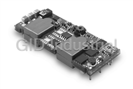
400 W, 9 -36 VDC Vin, Single Output, 48 VDC@8.3 A DC-DC Converter
Part Number
CFB400W-24S48
Price
Request Quote
Manufacturer
CINCON
Lead Time
Request Quote
Category
Capacitors » DC-DC Converter
Specifications
Manufacturer
Cincon
Manufacturers Part #
CFB400W-24S48
Industry Aliases
CFB400W-24S48
Series
CFB400W
Factory Pack Quantity
1
Dimensions
4.60 x 2.40 x 0.50"
Efficiency
86.50%
Input Voltage Nominal
24 VDC
Isolation
1500 VDC
Mechanical Style
Isolated
Mounting
Through Hole
Number of Outputs
1
Operating Temperature
- 40 to + 100°C
Output Amps 1
8.3 A
Output Voltage V1 Nominal
48 VDC
Power
400 W
Subcategory
DC-DC Converter
Datasheet

Extracted Text
V11 CFB400W SERIES 400W WATTS 4:1 INPUT ︳ DC-DC CONVERTERS SINGLE OUTPUT FEATURES * 400W Isolated Output * Efficiency to 90% * Fixed Switching Frequency * Input Under Voltage Protection * Over Temperature Protection * Over Voltage/Current Protection * Remote ON/OFF * Full-Brick Size Meet Industry Standard * Fully Isolated 1500VDC * Without Tantalum Capacitor Inside * CE Mark Meets 2004/108/EC CAPACITIVE (%) EFF. OUTPUT CURRENT INPUT CURRENT MODEL INPUT OUTPUT LOAD MAX. NUMBER VOLTAGE VOLTAGE (2) (3) MIN. MAX. NO LOAD FULL LOAD (4, 5, 6) CFB400W-24S05 9-36 VDC 5 VDC 0 mA 80 A 600 mA 86.5 87.5 10000uF 19.05 A 19.36 A CFB400W-24S12 9-36 VDC 12 VDC 0 mA 33.3 A 120 mA 85 86 10000uF 19.19 A CFB400W-24S24 9-36 VDC 24 VDC 0 mA 16.7 A 120 mA 88 87 4700uF 19.18 A CFB400W-24S28 9-36 VDC 28 VDC 0 mA 14.3 A 120 mA 86.5 87 4700uF CFB400W-24S48 9-36 VDC 48 VDC 0 mA 8.3 A 120 mA 85.5 86.5 2200uF 19.19 A CFB400W-48S05 18-75 VDC 5 VDC 0 mA 80 A 300 mA 88.5 89 10000uF 9.36 A 9.41 A CFB400W-48S12 18-75 VDC 12 VDC 0 mA 33.3 A 60 mA 88.5 88.5 10000uF 9.28 A CFB400W-48S24 18-75 VDC 24 VDC 0 mA 16.7 A 60 mA 90 90 4700uF 9.27 A CFB400W-48S28 18-75 VDC 28 VDC 0 mA 14.3A 60 mA 90.5 90 4700uF CFB400W-48S48 18-75 VDC 48 VDC 0 mA 8.3 A 60 mA 88 89.5 2200uF 9.27 A NOTE: 1. Nominal Input Voltage 24, 48 VDC. 2. Measured at 12VDC for 24Vin, 24VDC for 48Vin. 3. Measured at Nominal Input Voltage. 4. The output terminal of 12V, 24V, 28V Vout models required a minimum capacitor 330uF to maintain specified regulation. 5. The output terminal of 5Vout models required a minimum capacitor 680uF to maintain specified regulation. 6. The output terminal of 48Vout models required a minimum capacitor 100uF to maintain specified regulation. 1 V11 SPECIFICATIONS All Specifications Typical At Nominal Line, Full Load, and 25℃ Unless Otherwise Noted INPUT SPECIFICATIONS: GENERAL SPECIFICATIONS: Efficiency .................…..................................……..........…....... See Table Input Voltage Range ....……………............. 24V ............................ 9-36V Isolation Voltage ..................... Input/Output ....………..….. 1500VDC min. 48V ………............... 18-75V Input/Case .…...........…….. 1500VDC min. Under Voltage Lockout ………..….. 24Vin power up ….…..……..…. 8.5V Output/Case ………....…… 1500VDC min. 24Vin power down ………….…. 7.5V 7 Isolation Resistance .............................…............………..... 10 ohm min. 48Vin power up …….…...….…. 17V Isolation Capacitance …………………………………………… 4000pF typ. 48Vin power down …………..… 15V Switching Frequency ....................…………….……....……… 230KHz typ. Input Over Voltage Protection ….. 24Vin Turn off … 42V, Turn on ... 40V Operating Case Temperature …………………....……........ -40℃ to 100℃ 48Vin Turn off … 83V, Turn on … 80V Storage Temperature ……….………....…....……............ -55℃ to +110℃ Opto Isolated Remote ON/OFF (note6) Thermal Shutdown Case Temp. .……….………………..……. 110℃ typ. Input Filter …………………………………………………...……... LC Type Humidity .................................................... 95% RH max. Non condensing OUTPUT SPECIFICATIONS: Voltage Accuracy ........................................…………............ ±1.5% max. MTBF ………. MIL-HDBK-217F, GB, 25℃, Full Load ……… 340Khrs typ. Transient Response: 25% Step Load Change .……………..…… <500µs Dimensions ..................... 4.60×2.40x0.50 inches (116.8x61.0×12.7 mm) External Trim Adj. Range ………….…………………………….. 80-110% Case Material ................….....…… Aluminum Baseplate with Plastic Case Load share Accuracy …………………… ±10% at 50% to 100%Full Load Weight …………………………………………………………………… 220g Auxiliary Output Voltage/Current …………….…… 10±3Vdc/20mA max. NOTE : Ripple & Noise, 20MHz BW (note3) 1. Measured from high line to low line. 5V ……………...... 40mV RMS max., 100mV pk-pk max. 2. Measured from full load to zero load. 12V ……….…….... 60mV RMS max., 120mV pk-pk max. 3. Output ripple and noise measured with 10uF tantalum and 1uF 24V ……………... 100mV RMS max., 240mV pk-pk max. ceramic capacitor across output. 28V ……………... 100mV RMS max., 280mV pk-pk max. 4. The output adjustment circuit and trim equations show as figure1 and 48V ………….….. 120mV RMS max., 480mV pk-pk max. figure2. Temperature Coefficient ....................………..............…..... ±0.03%/°C 5. An external input capacitor 1000uF for 24Vin or 330uF for 48Vin Short Circuit Protection .........………………......................... Continuous models are recommended to reduce input ripple voltage. Line Regulation (note1) ……………….………..................…. ±0.2% max. 6. Standard model is negative logic , suffix “P” to the model number with Load Regulation (note2) ………………………….........…....... ±0.5% max. positive logic. (refer application note) Over Voltage Protection Trip Range, % Vo nom. ..................... 115-140% 7. If the remote sense feature is not to be used, the +sense pin should be Current Limit .................…………………... 110% ~150% Nominal Output connected to the +Vout pin and the –sense pin should be connected Start up time …………………………………………………….. 120ms typ. to the -Vout pin. (refer application note) CASE FB All Dimensions In Inches(mm) Pin DIA Tolerances Inches: .XX±0.02 .XXX±0.010 ±0.004 Millimeters: .X±0.5 .XX±0.25 ±0.1 4.099[104.11] 3.949[100.30] 3.799[96.49] 3.649[92.68] 3.499[88.87] PIN CONNECTIONS 3.349[85.06] PIN NUMBER FUNCTION 1 -Vin 10 -Vo 2 +Vin 1 9 -Vin -Vo 3 -ON/OFF 8 2 -Vo 4 +ON/OFF +Vin - 7 5 - 7 +Vo 3 +Vo 4 6 8 - 10 -Vo + +Vo 5 +Vo 11 -S 12 +S 0.199[5.05] 13 TRIM 4.20[106.7] Mounting Inserts 14 PC/NC 3.5 Through 4Pl. 15 IOG 16 AUX 4.60[116.8] The output voltage can be determined by Output Voltage = TRIM below equations: Terminal Voltage * Nominal Rt × 33 Output Voltage 1.24 × ( ) Rt + 33 Vf = Rt × 33 7.68 + Rt + 33 Fig.2 The schematic of Vout = (Vo + VR) × Vf output voltage adjusted by Unit: KΩ using external DC voltage. Vo: Nominal Output Voltage Rt=6.8KΩ Fig.1 The schematic of output voltage adjusted by using external resistor and/or variable resistor. 2 1.701[13.20] 1.301[33.04] 0.901[22.88] 0.22[5.5] 0.751[19.07] 0.50[12.7] ON/OFF 16 AUX 15 IOG 14 PC/NC 13 TRIM 12 +S 11 -S 0.400[10.16] 0.900[22.86] 0.501[12.72] 1.400[35.56] 0.20[5.1] 2.00[50.8] 2.251[57.17] 2.40[61.0]
Frequently asked questions
How does Electronics Finder differ from its competitors?

Is there a warranty for the CFB400W-24S48?
Which carrier will Electronics Finder use to ship my parts?
Can I buy parts from Electronics Finder if I am outside the USA?
Which payment methods does Electronics Finder accept?
Why buy from GID?

Quality
We are industry veterans who take pride in our work

Protection
Avoid the dangers of risky trading in the gray market

Access
Our network of suppliers is ready and at your disposal

Savings
Maintain legacy systems to prevent costly downtime

Speed
Time is of the essence, and we are respectful of yours
Related Products
30 W, 36 -75 VDC Vin, Single Output, 5 VDC@15 A DC-DC Converter
36 W, 36 -75 VDC Vin, Single Output, 12 VDC@7 A DC-DC Converter
45 W, 36 -75 VDC Vin, Single Output, 1 VDC@30 A DC-DC Converter
54 W, 36 -75 VDC Vin, Single Output, 1.2 VDC@30 A DC-DC Converter
62.5 W, 36 -75 VDC Vin, Single Output, 1.5 VDC@30 A DC-DC Converter
66 W, 36 -75 VDC Vin, Single Output, 1.8 VDC@30 A DC-DC Converter
Request a Quote

The quote request has been received
Close

Facing challenges or have inquiries? Feel free to contact us!
Call Us +1-469-283-2440
What they say about us
FANTASTIC RESOURCE
One of our top priorities is maintaining our business with precision, and we are constantly looking for affiliates that can help us achieve our goal. With the aid of GID Industrial, our obsolete product management has never been more efficient. They have been a great resource to our company, and have quickly become a go-to supplier on our list!
Bucher Emhart Glass
EXCELLENT SERVICE
With our strict fundamentals and high expectations, we were surprised when we came across GID Industrial and their competitive pricing. When we approached them with our issue, they were incredibly confident in being able to provide us with a seamless solution at the best price for us. GID Industrial quickly understood our needs and provided us with excellent service, as well as fully tested product to ensure what we received would be the right fit for our company.
Fuji
HARD TO FIND A BETTER PROVIDER
Our company provides services to aid in the manufacture of technological products, such as semiconductors and flat panel displays, and often searching for distributors of obsolete product we require can waste time and money. Finding GID Industrial proved to be a great asset to our company, with cost effective solutions and superior knowledge on all of their materials, it’d be hard to find a better provider of obsolete or hard to find products.
Applied Materials
CONSISTENTLY DELIVERS QUALITY SOLUTIONS
Over the years, the equipment used in our company becomes discontinued, but they’re still of great use to us and our customers. Once these products are no longer available through the manufacturer, finding a reliable, quick supplier is a necessity, and luckily for us, GID Industrial has provided the most trustworthy, quality solutions to our obsolete component needs.
Nidec Vamco
TERRIFIC RESOURCE
This company has been a terrific help to us (I work for Trican Well Service) in sourcing the Micron Ram Memory we needed for our Siemens computers. Great service! And great pricing! I know when the product is shipping and when it will arrive, all the way through the ordering process.
Trican Well Service
GO TO SOURCE
When I can't find an obsolete part, I first call GID and they'll come up with my parts every time. Great customer service and follow up as well. Scott emails me from time to time to touch base and see if we're having trouble finding something.....which is often with our 25 yr old equipment.
ConAgra Foods