

 Manufacturers
E-T-A 106-M2-P10-0.6A
Description
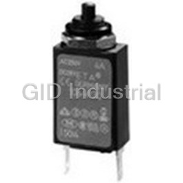
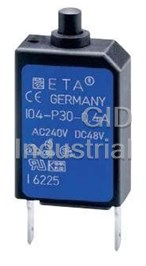
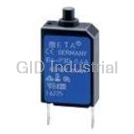
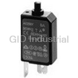
Circuit Breaker Thermal 1Pole 0.6A 240VAC/28VDC
106-M2-P10-0.6A
Part Number
106-M2-P10-0.6A
Price
Request Quote
Manufacturer
E-T-A
Lead Time
Request Quote
Category
Circuit Protection » Circuit Breaker
Specifications
Manufacturer
E-T-A
Manufacturers Part #
106-M2-P10-0.6A
Sub-Category
Circuit Breakers
Factory Pack Quantity
1
Datasheet

Extracted Text
Thermal Overcurrent Circuit Breakers 104/105/106-... Description Miniaturised single pole thermal circuit breaker with push-to-reset tease free, trip-free, snap action mechanism (R-type TO CBE to EN 60934). Available in versions for PCB or panel mounting, snap-in or threadneck, or as an integral type. Manual release facility optional for type 105. Approved to CBE standard EN 60934 (IEC 60934). For higher current ratings see type 1140. 1 Typical applications Motors, transformers, solenoids, printed circuit boards, hand-held machines and appliances, marine applications, caravans. 104-... 105-... 106-... Ordering information Technical data Type No. For further details please see chapter: Technical Information 104 PCB mounting type (-PR), or integral type (-P30/P10) Voltage rating AC 240 V; DC 48 V 105 snap-in panel mounting (UL: AC 250 V; DC 48 V) 106 threadneck panel mounting with hex and knurled nut * Current ratings 0.05...10 A 106-M2 threadneck panel mounting 3/8-27UNS with collar, hex nut and knurled nut* Auxiliary circuit 0.5 A, AC 240 V, DC 28 V Terminal design Typical life P10 blade terminals A6.3-0.8 (QC .250) AC 240 V 0.05...8 A 2,000 operations at 1 x I , inductive N P30 blade terminals A2.8-0.8 (QC .110) 0.05...5 A 3,000 operations at 2 x I , inductive N PR solder terminal pins for PCB mounting (type 104 only) 6...8 A: 500 operations at 2 x I , inductive N PR2 PCB mounting (vertical), type 104 only up to 6 A DC 48 V 0.05...8 A 2,000 operations at 1 x I , inductive N PR3 PCB mounting (vertical), type 104 only 0.05...5 A 3,000 operations at 2 x I , inductive N Shunt terminal (optional) 6...8 A: 500 operations at 2 x I , inductive N A3 same as main terminals (up to I 6 A/3 A max. load) N 10 A 200 operations at 1 x I , inductive N Manual release facility (optional) 10 A 50 operations at 2 x I , inductive N H only with type 105 Ambient temperature -20...+60 °C (-4...+140 °F) T 60 Auxiliary contacts (optional) Insulation co-ordination rated impulse pollution Si51 type 104 only (IEC 60664 and 60664 A) withstand voltage degree Current ratings 2.5 kV 2 0.05...10 A reinforced insulation in operating area 106 - P30 - .. - .. - .. - 5 A = ordering example Dielectric strength test voltage (IEC 60664 and 60664A) The exact part number required can be built up from the table of choices shown operating area AC 3,000 V above. Ordering references for optional features should be omitted if not required. Insulation resistance > 100 MΩ (DC 500 V) * mounting hardware bulk shipped Interrupting capacity I 0.05...8 A 6 x I AC cn N > 8...10 A 5 x I AC N 0.05...10 A 6 x I DC N Interrupting capacity I U N N (UL 1077) 0.05...10 A AC 250 V 2,000 A 0.05...10 A DC 48 V 200 A Degree of protection operating area IP40 (IEC 60529/DIN 40050) terminal area IP00 Vibration 10 g (57-500 Hz),±0.76 mm (10-57 Hz), Standard current ratings and typical internal resistance values to IEC 60068-2-6, test Fc, 10 frequency cycles/axis Current Internal Current Internal Shock 25 g ( 11 ms) to IEC 60068-2-27, test Ea rating (A) resistance (Ω) rating (A) resistance (Ω) Corrosion 96 hours at 5 % salt mist, 0.05 285 1.8 0.28 to IEC 60068-2-11, test Ka 0.08 134 2 0.25 Humidity 240 hours at 95 % RH, 0.1 81 2.5 0.18 to IEC 60068-2-3, test Ca 0.2 22 3 0.11 Mass approx. 10 g 0.3 8.7 3.5 0.076 0.4 5.5 4 0.067 0.5 3.3 4.5 0.051 Approvals 0.6 2.45 5 ≤ 0.05 0.7 1.6 6 ≤ 0.05 Authority Voltage ratings Current ratings 0.8 1.45 7 ≤ 0.05 VDE, SEV, AC 240 V 0.05...8 A 1 0.9 8 ≤ 0.05 Kema (EN 60934) DC 48 V 0.05...10 A CSA, UL AC 250 V; DC 48 V 0.05...10 A 1.2 0.6 10 ≤ 0.05 1.5 0.4 Circuit breakers with -Si51 not approved 06/07 www.e-t-a.com 1 - 13 Thermal Overcurrent Circuit Breakers 104/105/106-... Dimensions 104-P30 104-PR ø7 .276 ø4 ø4 .157 .157 1 PCB mounting holes blade terminals hole for 104-PR 104-PR DIN 46244-A2.8-0.8 mounting screw M2 104-PR-A3 7...10 A (QC .110) usable depth 4.5 mm (.177 in.) cut-out dimensions 6.5 0.05...6 A 0.5 0.5 6.5 .256 terminal design for .020 .020 correct stand-off distances .256 1 0.8 .039 .031 9 .354 19 .748 12 3 12 9.1 104-P30 104-P30-A3 ±0.2 .358 8 17.5 ±.008 7...10 A 0.05...6 A .315 ø1.5 .689 9.5 9.5 19.2 .059 .374 .374 .756 ±0.2 17.5 8 21 ±.008 .689 .315 .827 104-PR3 0.05...6 A ø7 104-PR-(A3)-Si51 .276 ø4 ø7 .157 .276 ø4 .157 4 1.2 0.8 .157 .047 .031 15.4 0.9 .606 .035 1.2 terminal design for .047 correct stand-off distances 1 0.8 PCB mounting holes .039 .031 hole for mounting screw M2x5 0.05...6 A 6.5 (A3) 7.7 .256 .303 9 .354 17.5 .689 9.1 19 15.4 .358 .748 .606 19.2 21 .756 .827 PCB mounting holes 7...10 A 12.5 5.4 104-PR-Si51 104-PR-Si51 .492 12.5 .213 104-PR-A3-Si51 7...10 A 9.5 7...10 A .492 0.05...6 A ø1 ø1 .374 5 5 .039 .039 .197 .197 5 5 7.7 4 4 .303 5.4 4 .213 .157 1231 2 ±0.2 8 ±0.2 8 ±.008 ±.008 .315 .315 17.5 ø1.5 9.5 ø1.5 .689 .059 .059 .374 mm This is a metric design and millimeter dimensions take precedence ( ) inch 1 - 14 www.e-t-a.com 06/07 10 OFF max. 3 max. 3 9.5 OFF max .118 .394 max .118 .374 1.2 6.5 ON 1.2 6.5 ON 21.5 .047 .256 .256 .047 .846 23.5 3.5 21 .925 11 .827 .138 9.5 11 23 .433 4.5 .374 .906 .433 27.6 .177 27.6 1.09 1.09 29.6 31.6 Ø 2.2 1.16 1.24 21.5 .087 .846 ø0.9 .035 23.5 .925 7.3 .287 9.5 max. 3 9.5 OFF OFF max .118 .374 .374 1.2 6.5 ON 10 ON 6.5 .047 .256 .394 .256 11 3.5 11 .433 max. 3 1.2 .138 4.5 .433 27.6 max .118 .047 .177 1.09 27.6 1.09 30 29.6 29.6 1.16 1.18 4 1.17 .157 0.9 0.9 .035 .035 ø1.5 .059 30 1.18 2.1 6.2 .244 .083 ø1.5 .059 Thermal Overcurrent Circuit Breakers 104/105/106-... Dimensions 104-PR2 ø7 106-P30 0.05...6 A 3 / -27UNS-2A 8 .276 tightening torque max. 0.8 Nm ø4 .157 ø4 .157 1 2 7 .276 .079 0.8 15 7 .031 .591 .276 19 11 6.5 .748 blade terminals hole for mounting .433 .256 DIN 46244-A2.8-0.8 screw M2x5 15.7 (QC .110) .618 mounting hole SW14 .551 9.1 .358 19.2 .756 105-P30 ø7 ø4 9 9.6 .157 .157 .276 - 0.1 .354 .378 - .004 106-P30 106-P30-A3 7...10 A 0.05...6 A 11 19 106-M2 .748 .433 blade terminals 3 / -27UNS-2A 8 DIN 46244-A2.8-0.8 tightening torque max. 0.8 Nm (QC .110) mounting hole panel cut-out a 12 .472 25 .984 9.6 - 0.1 .378 d a b - .004 mm inch mm inch 0.8 .031 21.9 .862 +0.3 11.3 1.0 .039 22 .866 +.012 .445 1.5 .059 22.1 .870 2-3 .079-.118 22.2 .874 105- 105-P30-A3 Terminal design P307...10 A 0.05...6 A 104/105/106-P10 3.8 0.05...6 A 7...10 A .150 105-P..-H ø4 ø7 blade terminals DIN 46244-A6.3-0.8 .157 .276 (QC .250) 6.3 .248 polarizing tooth 104/105/106-P10-A3 104/105/106-P30-A3 0.05...6 A 0.05...6 A 11 .433 5.3 polarizing tooth .209 12 .472 25 .984 mm This is a metric design and millimeter dimensions take precedence ( ) inch 06/07 www.e-t-a.com 1 - 15 9.5 OFF max. 3 38.5 9.5 OFF 9.5 OFF max .118 .374 1.52 .374 .374 1.2 6.5 ON 6.5 ON 6.5 ON .256 .047 .256 .256 11 ±0.4 2 14 max. 3 1.2 .433 14 .079 ±.016 9.5 max .118 .047 .551 2 .551 27.6 .374 .079 27.6 1.09 1.09 29.6 29.6 1.17 1.16 3.6 .142 b d max. 3 13.5 OFF max .118 .531 8.8 1.2 10.5 ON 10 .346 .047 .413 .394 0.7 .028 9.5 27.6 7 1.09 .374 .276 9.5 .374 8.9 8.9 - 0.1 - 0.1 .350 .350 - .004 - .004 Thermal Overcurrent Circuit Breakers 104/105/106-... Installation drawings Internal connection diagrams operating area Types 104 Types 104-...-A3 Type 104-...-A3-Si51 104-… 105 105-...-A3 106 106-...-A3 1 1 1 5 3 3 4 1 2 2 2 mounting area 8 8 .315 .315 Typical time/current characteristics at +23°C/+73.4°F operating area 105-… 10000 0.05 - 6 A 7 - 10 A 1000 100 8 8 .315 .315 mounting area 10 106-… operating area 1 0.1 12 46810 20 40 … times rated current The time/current characteristic curve depends on the ambient temperature prevailing. In order to eliminate nuisance tripping, please multiply the circuit breaker current ratings by the derating factor shown below. See also section 9 – Technical information. 8 mounting area 8 Ambient temperature °F -4 +14 +32 +73.4 +104 +122 +140 .315 .315 °C -20 -10 0 +23 +40 +50 +60 Derating factor 0.76 0.84 0.92 1 1.08 1.16 1.24 Accessories Water splash cover (transparent)/knurled nut assembly (type 106-... only) X 201 285 01 Degree of protection IP 64 mm This is a metric design and millimeter dimensions take precedence ( ) inch All dimensions without tolerances are for reference only. In the interest of improved design, performance and cost effectiveness the right to make changes in these specifications without notice is reserved.Product markings may not be exactly as the ordering codes. Errors and omissions excepted. 1 - 16 www.e-t-a.com 06/07 .315 .315 .315 .315 .315 .315 Trip time in seconds 8 8 8 8 8 8
Frequently asked questions
How does Electronics Finder differ from its competitors?

Is there a warranty for the 106-M2-P10-0.6A?
Which carrier will Electronics Finder use to ship my parts?
Can I buy parts from Electronics Finder if I am outside the USA?
Which payment methods does Electronics Finder accept?
Why buy from GID?

Quality
We are industry veterans who take pride in our work

Protection
Avoid the dangers of risky trading in the gray market

Access
Our network of suppliers is ready and at your disposal

Savings
Maintain legacy systems to prevent costly downtime

Speed
Time is of the essence, and we are respectful of yours
Related Products
MINIATURISED SINGLE POLE THERMAL CIRCUIT BREAKER WITH PUSH-TO-RESET TEASE FREE, TRIP-FREE, SNAP ACTI...
MINIATURISED SINGLE POLE THERMAL CIRCUIT BREAKER WITH PUSH-TO-RESET TEASE FREE, TRIP-FREE, SNAP ACTI...
Circuit Breaker Thermal 1Pole 2A 240VAC/28VDC
Circuit Breaker Thermal 1Pole 4A 240VAC/28VDC
Circuit Breaker Thermal 1Pole 0.2A 240VAC/48VDC 104-PR-0.2A
Circuit Breaker Thermal 1Pole 0.3A 240VAC/48VDC 104-PR-0.3A
Request a Quote

The quote request has been received
Close

Facing challenges or have inquiries? Feel free to contact us!
Call Us +1-469-283-2440
What they say about us
FANTASTIC RESOURCE
One of our top priorities is maintaining our business with precision, and we are constantly looking for affiliates that can help us achieve our goal. With the aid of GID Industrial, our obsolete product management has never been more efficient. They have been a great resource to our company, and have quickly become a go-to supplier on our list!
Bucher Emhart Glass
EXCELLENT SERVICE
With our strict fundamentals and high expectations, we were surprised when we came across GID Industrial and their competitive pricing. When we approached them with our issue, they were incredibly confident in being able to provide us with a seamless solution at the best price for us. GID Industrial quickly understood our needs and provided us with excellent service, as well as fully tested product to ensure what we received would be the right fit for our company.
Fuji
HARD TO FIND A BETTER PROVIDER
Our company provides services to aid in the manufacture of technological products, such as semiconductors and flat panel displays, and often searching for distributors of obsolete product we require can waste time and money. Finding GID Industrial proved to be a great asset to our company, with cost effective solutions and superior knowledge on all of their materials, it’d be hard to find a better provider of obsolete or hard to find products.
Applied Materials
CONSISTENTLY DELIVERS QUALITY SOLUTIONS
Over the years, the equipment used in our company becomes discontinued, but they’re still of great use to us and our customers. Once these products are no longer available through the manufacturer, finding a reliable, quick supplier is a necessity, and luckily for us, GID Industrial has provided the most trustworthy, quality solutions to our obsolete component needs.
Nidec Vamco
TERRIFIC RESOURCE
This company has been a terrific help to us (I work for Trican Well Service) in sourcing the Micron Ram Memory we needed for our Siemens computers. Great service! And great pricing! I know when the product is shipping and when it will arrive, all the way through the ordering process.
Trican Well Service
GO TO SOURCE
When I can't find an obsolete part, I first call GID and they'll come up with my parts every time. Great customer service and follow up as well. Scott emails me from time to time to touch base and see if we're having trouble finding something.....which is often with our 25 yr old equipment.
ConAgra Foods