

 Manufacturers
E-T-A 3120-F324-P7T1-W15FB3-16A

Description
Circuit Breaker Thermal 2Pole 16A 240VAC/50VDC
3120-F324-P7T1-W15FB3-16A
Part Number
3120-F324-P7T1-W15FB3-16A
Price
Request Quote
Manufacturer
E-T-A
Lead Time
Request Quote
Category
Circuit Protection » Circuit Breaker
Specifications
Manufacturer
E-T-A
Manufacturers Part #
3120-F324-P7T1-W15FB3-16A
Sub-Category
Circuit Breakers
Factory Pack Quantity
1
Datasheet

Extracted Text
Thermal Overcurrent Circuit Breaker 3120-F... Description An extremely versatile range of rocker switch/thermal circuit breakers (S- type TO CBE to EN 60934 with trip free mechanism) offering the choice of single pole, double pole with single pole protection, and double pole with protection on both poles. Designed for snap-in panel mounting with versions available for three different panel cut-out sizes. Illumination is optional and there is a range of colours and markings for the rocker. Under overload conditions the rocker returns to the OFF position. 6-way frame for 3120-F5 available upon request. 1 Any one of the following additional function modules can be supplied factory fitted to the rear of the switch/circuit breaker. ● Under voltage release coil (for double pole versions only). ● Magnetic trip coil for short circuit protection. ● Magnetic trip coil for remote relay trip. ● Auxiliary contacts for status signalling. ● Mechanical slide interlock. 3120-F... Approved to CBE standard EN 60934 (IEC 60934). Typical applications Technical data Motors, transformers, solenoids, extra low voltage wiring systems, office For further details please see chapter: Technical Information machines, electro-medical equipment, power supplies, communications Voltage rating AC 240 V; DC 50 V systems, medical equipment to EN 60601. (AC 415 V to special order) (UL: AC 250 V; DC 50 V) Current ratings 0.1...20 A Standard current ratings and typical internal resistance values (up to 30 A to special order, single pole only) Typical life 1-pole Current Internal resistance Current Internal resistance AC 240 V: 0.1...20 A 30,000 operations at 1 x I , inductive N rating (A) per pole (Ω) rating (A) per pole (Ω) DC 50 V: 0.1...4 A 30,000 operations at 1 x I , inductive N 0.1 94 3.5 0.0565 4.5...16 A 30,000 operations at 1 x I , resistive N DC 28 V: 4.5...20 A 30,000 operations at 1 x I , inductive 0.2 24 4 0.0435 N 2-pole 0.3 12 4.5 0.0435 AC 415 V: 0.1...16 A 10,000 operations at 1 x I , inductive N 0.4 5.30 5 0.0325 AC 240 V: 0.1...16 A 50,000 operations at 1 x I , inductive N 17...20 A 30,000 operations at 1 x I , inductive 0.5 4.20 6 0.0215 N DC 50 V: 0.1...16 A 50,000 operations at 1 x I , inductive N 0.6 2.90 7 0.0165 17...20 A 10,000 operations at 1 x I , inductive N 0.8 1.50 8 0.0165 Ambient temperature -30...+60 °C (-22...+140 °F) 1 0.9 10 < 0.02 Insulation co-ordination rated impulse pollution 1.2 0.80 12 < 0.02 (IEC 60664 and 60664 A withstand voltage degree 2.5 kV 2 1.5 0.45 14 < 0.02 reinforced insulation in operating area 2 0.27 16 < 0.02 Dielectric strength 2.5 0.0785 18 < 0.02 (IEC 60664 and 60664A) test voltage 3 0.0595 20 < 0.02 operating area AC 3,000 V between poles (2-pole) AC 1,500 V Insulation resistance > 100 MΩ (DC 500 V) Interrupting capacity I 0.1...2 A 10 x I Illumination voltage/power consumption cn N 2.5...20 A 250 A 2-pole, or 150 A 1-pole Interrupting capacity I U 2-pole N N operating voltage power consumption (UL 1077) 0.1...2 A AC 250 V 200 A filament/neon LED 2.5...3 A AC 250 V 1,000 A 6 V 60 mA 9 mA 3.5...8 A AC 250 V 2,000 A 12 V 20 mA 9 mA 9...16 A AC 250 V 3,500 A 18...20 A AC 250 V 5,000 A 24 V 20 mA 9 mA 0.1...20 A DC 50 V 1,000 A 48 V 20 mA 1.5 mA Degree of protection operating area IP40 115 V < 1.5 mA < 1 mA* (IEC 60529/DIN 40050) (IP54 with water splash protection) 230 V < 1.5 mA < 1 mA* terminal area IP00 * single pole version only Vibration 8 g (57-500 Hz), ±0.61 mm (10-57 Hz) to IEC 60068-2-6, test Fc 10 frequency cycles/axis Shock 30 g (11 ms) Approvals to IEC 60068-2-27, test Ea Corrosion 96 hours at 5 % salt mist, Authority Voltage ratings Current ratings to IEC 60068-2-11, test Ka VDE (EN 60934) AC 240 V; DC 28 V 0.1...20 A DC 50 V 0.1...20 A 2-pole Humidity 240 hours at 95 % RH, DC 50 V 0.1...10 A 1-pole to IEC 60068-2-3, test Ca UL, CSA AC 250 V; DC 50 V 0.1...20 A Mass approx. 33 g (double pole) CCC AC 250 V; DC 50 V 0.1...20 A approx. 27 g (single pole) 06/07(120307) www.e-t-a.com 1 - 59 Thermal Overcurrent Circuit Breaker 3120-F... Ordering information Typical time/current characteristics Type No. 3120 rocker switch/circuit breaker single or double pole load Mounting 0.1 … 2 A F snap in frame Size of frame panel thickness 10000 +60 °C +140 °F 3 to fit mounting cut-out 50.5 x 21.5 mm 1-6.35 mm (.039-.250 in) 5 to fit mounting cut-out 44.5 x 22 mm 1-4 mm (.039-.157 in) +23 °C +73.4 °F 6 to fit mounting cut-out 45 x 33.7 mm 1.2-2.4 mm (.047-.094 in) 1 -30 °C Number of poles 1000 -22 °F 0 2-pole, unprotected, switch only 1 1-pole, thermally protected 2 2-pole, thermally protected 5 2-pole, thermally protected on one pole only (terminals 11,12k,12i) 100 6 1-pole, unprotected, switch only Mounting frame design 1 collar height 1 mm 3 collar height 9 mm 4 collar height 2 mm with water splash protection (IP54), not with -F6... 10 U with water splash protection and actuator guard Terminal configuration P7 blade terminals 2x2.8x0.8 mm (QC 2x.110) (terminals 12(k), 22(k), 11, 21), not for under voltage 1 module, not for switch H7 12(k), 22(k): blade terminals 2x2.8-0.8 (QC 2x.110) 11, 21: terminal screws, not for switch N7 as P7, but including shunt terminals 12(i) and 22 (i) 0.1 as blade terminals 2x2.8x0.8 mm(QC 2x.110) 12 46810 20 40 not for under voltage module … times rated current G7 as H7, but including shunt terminals 12(i) and 22 (i) 2.5 … 20 A as blade terminals 2x2.8x0.8 mm(QC 2x.110) 10000 +60 °C Characteristic curve +140 °F T1 thermal, 1.01-1.4 x I N +23 °C +73.4 °F Q1 switch only Actuator style -30 °C 1000 -22 °F W rocker U momentary switch Switch colour designation opaque translucent (for illuminated versions) 100 01 black 12 white 02 white 14 red 04 red 15 orange 19 green 10 Rocker markings A 0 AUS OFF B I EIN ON C 1 D 0 AUS OFF E I EIN ON F X AB C D E F X X = without marking 0.1 12 46810 20 40 Rocker illumination (optional) … times rated current B filament≤ 48V AC/DC; neon ≥115V AC G green LED, AC/DC Y yellow LED, AC/DC The time/current characteristic curve depends on the ambient temperature prevailing. In order to eliminate nuisance tripping, please multiply the circuit R red LED, AC/DC breaker current ratings by the derating factor shown below. See also Illumination voltage range section 9 – Technical information. 0 4 - 7 V (B,G,Y,R) Ambient temperature °F -22 -4 +14 +32 +73.4 +104 +122 +140 1 10 - 14 V (B,G,Y,R) °C -30 -20 -10 0 +23 +40 +50 +60 2 20 - 28 V (B,G,Y,R) Derating factor 0.8 0.76 0.84 0.92 1 1.08 1.16 1.24 3 90 - 140 V (B) 4 185 - 275 V (B) 5 42 - 54 V (B,Y,R) Current ratings 0.1...20 A 3120 - F 3 2 1 - N7 T1 - W 14 A B 4 - 10 A ordering example 3120 - F . 0 . - N7 Q1 -W .. . . . - 20 A (switch only) N.B. Switch only versions must be specified with -N7 or -G7 terminals. Terminals 12(k) and 22(k) are not fitted. 1 - 60 www.e-t-a.com 06/07(120307) Trip time in seconds Trip time in seconds Thermal Overcurrent Circuit Breaker 3120-F... Internal connection diagrams Mounting style variants 2-pole, 2-pole, Style F 3.3 collar height 9 mm (.354 in.) thermally protected on both poles thermally protected on one pole only 25 54 line line .984 11 21 11 21 2.13 19.5 35 1.38 .768 12(i) 22(i) 12(i) 22(i) 1 12(k) 22(k) 12(k) load load 1-pole, 2-pole, 12(i) 12(k) 11 thermally protected unprotected line line 11 11 21 10.7 3.5 3 .421 .138 .118 21 15.5 .827 .610 blade terminals DIN 46244-C-Ms-S 41 12(i) 22(i) (QC 2x.110) 1.61 12(i) 22(i) flat head screw M3.5x5-MS ISO1580 load tightening torque max. 0.8 Nm 12(k) load Style F 3.4 collar height 2 mm (.079 in.), with water splash protection 27 56 1.06 2.21 Dimensions 35 19.5 1.38 .768 Style F3.1 collar height 1 mm/.039 in. Actuating force max. 35 N optional illumination in ON position 25 12(i) 12(k) 11 OFF position .984 16 54 10.7 3.5 3 .630 2.13 .421 .138 .118 21 15.5 .827 .610 41 blade terminals DIN 46244-C-Ms-S 1.61 (QC 2x.110) flat head screw M3.5x5-MS ISO1580 tightening torque max. 0.8 Nm Style F 5.1 25 Optional illumination .984 16 48 .630 1.89 12(i) 12(k) 11 10.7 3.5 3 .421 .138 .118 21 15.5 12(i) 12(k) 11 .827 .610 41 blade terminals DIN 46244-C-Ms-S (QC 2x.110) 1.61 10.7 3.5 3 .421 .118 flat head screw ISO1580 M3.5x5-MS .138 21 15.5 tightening torque max. 0.8 Nm .827 .610 41 blade terminals DIN 46244-C-Ms-S (QC 2x.110) 1.61 flat head screw M3.5x5-MS ISO1580 tightening torque max. 0.8 Nm Installation drawing Style F 5.U with water splash protection (IP54) and actuator guard 50 27 1.97 1.06 24 44,2 -0,2 When installing the circuit breaker apply pressure on bezel only .945 1.74 -.008 21,5 -0,1 5,3 24,1 operating area .209 .949 .846-.004 19,5 35 .768 1.38 12(i) 12(k) 11 12(i) 12(k) 11 10,7 3,5 3 .421 .138 21 .118 15,5 .827 .610 blade terminals DIN 46244-C-Ms-S 41 7 7 8 710 1.61 .276 flat head screw M3.5x5-MS ISO1580 .276 .315 .276 .394 tightening torque max. 0.8 Nm mounting area Dimension diagram for style F6 is available on request. mm This is a metric design and millimeter dimensions take precedence ( ) inch 06/07(120307) www.e-t-a.com 1 - 61 35 7 1.38 .276 33 1.30 10 .394 10 .394 15.5 .610 35 7 3.8 10 35 9 37 1.38 .276 .150 1.38 .354 .394 1.46 33 33 33 33 1.30 1.30 1.30 1.29 10 .394 7 .276 4 .157 10 10 10 10 .394 .394 .394 .394 R3.5 .138 Thermal Overcurrent Circuit Breaker 3120-F... Accessories Insulated cover Rear terminal shroud black (IP64) Y 303 068 01 Y 304 275 01 2.5 40.5 .098 +0.5 1.59 1.75 20.5 -0.25 +.020 .069 .807 -.010 1 20 .787 Terminal adapter Y 303 862 01 4 .157 ø8 .315 Water splash cover, transparent (IP66) for style -F5.. X 221 619 01 48 blade terminal DIN 46244-C-Ms-S 1.89 (QC 2x.110) Spacer for 3120-F3... Y 303 675 01/02 58 ø8 2.28 .315 50.5 1.99 ø4.4 .173 * Y 303 675 01 suitable for * panel thickness < 2 mm (.079 in) * Y 303 675 02 suitable for panel thickness < 4 mm (.157 in) 60 2.36 Spacer for 3120-F5... 73 Y 303 676 01 2.87 52 6-way frame for 3120-F5... upon request 2.05 44.5 1.75 Cut-out dimensions 1 .039 Cut-out for mounting style -F3 Cut-out for mounting style -F6 with rocker and push button with rocker - 0.4 sharp-edged - 0.4 -.016 -.016 - 0.2 - 0.2 -.008 min. 2.5 -.008 min. 2 min .098 min .079 without bends max. R2 max. R1.5 max .059 max .079 ±0.05 ±0.05 ±.002 ±.002 max. R0.3 Blanking piece in -F3 frame +0.3 “A” 50.5 max. R0.3 max .012 Y 303 885 31 +.012 1.99 max .012 54 25 matt finish 2.13 .984 31 16.5 1.22 .650 Cut-out for mounting style -F5 - 0.4 with rocker -.016 - 0.2 min. 2 -.008 min .079 +1 +0.4 +0.8 max. R1.5 mm 1.2 1.6 2.4 panel max .059 +.016 +.031 +.039 thickness inch .047 .063 .094 ±0.05 +0,2 +1.1 +2.2 ±.002 45 45 mm 45 dimension - 0.05 - 0.05 - 0.05 +0.2 44.5 +.008 +.043 +.087 “A” inch 1.77 1.77 1.77 - .002 - .002 - .002 +.008 41 21 1.75 1.61 .827 max. R0.3 max .012 Edges of working parts: ISO 13715 All dimensions without tolerances are for reference only. In the interest of improved design, performance and cost effectiveness the right to make changes in these specifications without notice is reserved.Product markings may not be exactly as the ordering codes. mm This is a metric design and millimeter dimensions take precedence ( ) inch Errors and omissions excepted. 1 - 62 www.e-t-a.com 06/07(120307) +0.2 21.5 1-6.35 1-4 mm +.008 .846 .039-.250 .039-.157 in. 3.4 .134 10 50 .394 1.97 +0.3 22 +.012 .866 +0.2 33.7 - 0.05 panel thickness +.008 1.33 - .002 35 16.5 25 1.38 .650 .984 +5 70 +.197 2.76 1 .039 13.5 .531 1 4 .039 .157 0.9 .035 9 .354 3.7 0.8 22.5 22 .146 .031 .886 .866 2.5 28 28 .098 1.10 1.10 33 1.30 36 1.42 Thermal Overcurrent Circuit Breaker 3120-F7.. Description E-T-A’s proven type 3120 in a new attractive styling (S-type TO CBE to EN 60934 with trip free mechanism) offering the choice of single pole, double pole with single pole protection, and double pole with protection on both poles. Designed for snap-in panel mounting with illumination as an option. Under overload conditions the rocker returns to the OFF position. Any one of the following additional function modules can be supplied factory fitted to the rear of the switch/circuit breaker. ● Under voltage release coil (for double pole versions only). 1 ● Magnetic trip coil for short circuit protection. ● Magnetic trip coil for remote relay trip. ● Auxiliary contacts for status signalling. ● Mechanical slide interlock. Approved to CBE standard EN 60934 (IEC 60934). Available accessories: water splash protection and actuator guard to prevent 3120-F7.. inadvertent operation. Typical applications Technical data Motors, transformers, solenoids, extra low voltage wiring systems, office For further details please see chapter: Technical Information machines, electro-medical equipment, power supplies, communications Voltage rating AC 240 V; DC 50 V systems, boating. (AC 415 V to special order) (UL: AC 250 V; DC 50 V) Current ratings 0.1...20 A Standard current ratings and typical internal resistance values (up to 30 A to special order, single pole only) Typical life 1-pole Current Internal resistance Current Internal resistance AC 240 V: 0.1...20 A 30,000 operations at 1 x I , inductive N rating (A) per pole (Ω) rating (A) per pole (Ω) DC 50 V: 0.1...4 A 30,000 operations at 1 x I , inductive N 4.5...16 A 30,000 operations at 1 x I , resistive 0.1 94 3.5 0.0565 N DC 28 V: 4.5...20 A 30,000 operations at 1 x I , inductive N 0.2 24 4 0.0435 2-pole 0.3 12 4.5 0.0435 AC 415 V: 0.1...16 A 10,000 operations at 1 x I , inductive N AC 240 V: 0.1...16 A 50,000 operations at 1 x I , inductive 0.4 5.30 5 0.0325 N 17...20 A 30,000 operations at 1 x I , inductive N 0.5 4.20 6 0.0215 DC 50 V: 0.1...16 A 50,000 operations at 1 x I , inductive N 0.6 2.90 7 0.0165 17...20 A 10,000 operations at 1 x I , inductive N 0.8 1.50 8 0.0165 Ambient temperature -30...+60 °C (-22...+140 °F) 1 0.9 10 < 0.02 Insulation co-ordination rated impulse pollution (IEC 60664 and 60664 A withstand voltage degree 1.2 0.80 12 < 0.02 2.5 kV 2 1.5 0.45 14 < 0.02 reinforced insulation in operating area 2 0.27 16 < 0.02 Dielectric strength 2.5 0.0785 18 < 0.02 (IEC 60664 and 60664A) test voltage operating area AC 3,000 V 3 0.0595 20 < 0.02 between poles (2-pole) AC 1,500 V Insulation resistance > 100 MΩ (DC 500 V) Illumination voltage/power consumption Interrupting capacity I 0.1...2 A 10 x I cn N 2.5...20 A 250 A 2-pole, or 150 A 1-pole Interrupting capacity I U 2-pole operating voltage power consumption N N (UL 1077) 0.1...2 A AC 250 V 200 A filament/neon LED 2.5...3 A AC 250 V 1,000 A 6 V 60 mA 9 mA 3.5...8 A AC 250 V 2,000 A 12 V 20 mA 9 mA 9...6 A AC 250 V 3,500 A 18...20 A AC 250 V 5,000 A 24 V 20 mA 9 mA 0.1...20 A DC 50 V 1,000 A 48 V 20 mA 1.5 mA Degree of protection operating area IP40 115 V < 1.5 mA < 1 mA* (IEC 60529/DIN 40050) (IP54 with water splash protection) 230 V < 1.5 mA < 1 mA* terminal area IP00 * single pole version only Vibration 8 g (57-500 Hz), ±0.61 mm (10-57 Hz) to IEC 60068-2-6, test Fc 10 frequency cycles/axis Shock 30 g (11 ms) Approvals to IEC 60068-2-27, test Ea Corrosion 96 hours at 5 % salt mist, Authority Voltage ratings Current ratings to IEC 60068-2-11, test Ka VDE, (EN 60934) AC 240 V; DC 28 V 0.1...20 A DC 50 V 0.1...20 A 2-pole Humidity 240 hours at 95 % RH, DC 50 V 0.1...10 A 1-pole to IEC 60068-2-3, test Ca UL, CSA AC 250 V; DC 50 V 0.1...20 A Mass approx. 33 g (double pole) CCC AC 250 V; DC 50 V 0.1...20 A approx. 27 g (single pole) 06/07(120307) www.e-t-a.com 1 - 63 Thermal Overcurrent Circuit Breaker 3120-F7.. Ordering information Typical time/current characteristics Type No. 3120 rocker switch/circuit breaker single or double pole load Mounting F snap in frame 0.1 … 2 A Size of frame panel thickness 10000 +60 °C 7 to fit mounting cut-out 44.5x22mm(1.75x.866 in) 1-4 mm(.039-.157 in) +140 °F Number of poles +23 °C +73.4 °F 0 2-pole, unprotected, switch only 1 1 1-pole, thermally protected -30 °C 1000 -22 °F 2 2-pole, thermally protected 5 2-pole, thermally protected on one pole only (terminals 11,12k,12i) 6 1-pole, unprotected, switch only Mounting frame design N grey frame 100 P snap-on actuator guard grey Q snap-on water splash cover grey R black frame S snap-on actuator guard black 10 T snap-on water splash cover black Terminal configuration P7 blade terminals 2x2.8x0.8 mm (QC 2x.110) (terminals 12(k), 22(k),11, 21), not for under voltage module, 1 not for switch H7 12(k), 22(k): blade terminals 2x2.8-0.8 (QC 2x.110) 11, 21: terminal screws, not for switch N7 as P7, but including shunt terminals 12(i) and 22 (i) 0.1 as blade terminals 2x2.8x0.8 mm(QC 2x.110) 12 46810 20 40 not for under voltage module … times rated current G7 as H7, but including shunt terminals 12(i) and 22 (i) 2.5 … 20 A as blade terminals 2x2.8x0.8 mm(QC 2x.110) 10000 +60 °C Characteristic curve +140 °F T1 thermal, 1.01-1.4 x I N +23 °C Q1 switch only +73.4 °F Actuator style -30 °C 1000 A rocker -22 °F Switch colour designation 20 blue opaque 30 blue translucent Rocker markings 100 I 10 0 Q Q "I" and "0" moulded in 1 Push button illumination (optional) B filament, AC/DC G green LED, AC/DC R red LED, AC/DC Illumination voltage range (optional) 0.1 0 4 - 7 V (G,B,R) 12 46810 20 40 … times rated current 1 10 - 14 V (G,B,R) 2 20 - 28 V (G,B,R) 3 90 - 140 V (B) The time/current characteristic curve depends on the ambient temperature 4 185 - 275 V (B) prevailing. In order to eliminate nuisance tripping, please multiply the circuit 5 42 - 54 V (B,R) breaker current ratings by the derating factor shown below. See also Current ratings section 9 – Technical information. 0.1...20 A Ambient temperature °F -22 -4 +14 +32 +73.4 +104 +122 +140 °C -30 -20 -10 0 +23 +40 +50 +60 3120 - F 7 2 N - N7 T1 - A 20 Q B 4 - 10 A ordering example Derating factor 0.8 0.76 0.84 0.92 1 1.08 1.16 1.24 3120 - F . 0 N - N7 Q1 -A 20 Q B 4 - 20 A (switch only) N.B. Switch only versions must be specified with -N7 or -G7 terminals. Terminals 12(k) and 22(k) are not fitted. 1 - 64 www.e-t-a.com 06/07(120307) Trip time in seconds Trip time in seconds Thermal Overcurrent Circuit Breaker 3120-F7.. Dimensions Internal connection diagrams 2-pole, 2-pole, Style -F7.N and F7.R thermally protected on both poles thermally protected on one pole only 25 ±0.2 48 line line ±.008 .984 1.89 11 21 11 21 44.2 15.5 -0.2 .610 1.74 -.008 12(i) 22(i) 12(i) 22(i) 1 12(k) 22(k) 12(k) load load 1-pole, 2-pole, thermally protected unprotected LINE 12(i) 12(k) 11 line line 11 11 21 10.7 3.5 3 .421 .138 .118 12(i) 22(i) 21 15.5 12(i) 22(i) load .827 .610 41 12(k) load 1.61 blade terminals DIN 46244-C-Ms-S (QC 2 x .110) flat head screw ISO1580 M3.5x5-MS tightening torque max. 0.8 Nm Installation drawing Style -F7.P and F7.S 34 60 1.34 2.36 When installing the circuit breaker apply pressure on bezel only. 18.8 44.2 -0,2 .740 1.74 -.008 operating area 15.5 .610 LINE 12(i) 12(k) 11 LINE 12(i) 12(k) 11 3 3.5 10.7 .118 .421 .138 15.5 21 7 7 710 8 .827 .610 .276 .276 .315 .276 .394 41 mounting area 1.61 blade terminals DIN 46244-C-Ms-S (QC 2 x .110) flat head screw ISO1580 M3.5x5-MS tightening torque max. 0.8 Nm Panel cut-out Style -F7.Q and F7.T 34 60 1.34 2.36 18.6 44.8 -0,4 -.016 1.76 .732 -0,2 min. 2 -.008 min .079 max. R1.5 ±0,05 max .059 ±.002 +0.4 44.5 LINE max. R0.3 12(i) 12(k) 11 +.016 1.75 max .012 10.7 3.5 3 .421 .138 .118 Edges of working parts: ISO 13715 15.5 21 .827 .610 41 1.61 blade terminals DIN 46244-C-Ms-S (QC 2 x .110) flat head screw ISO1580 M3.5x5-MS tightening torque max. 0.8 Nm mm This is a metric design and millimeter dimensions take precedence ( ) inch 06/07(120307) www.e-t-a.com 1 - 65 8.9 33 33 33 8.9 .350 .350 1.30 1.30 1.30 10 10 10 3 11.5 5.9 .394 .118 .394 .394 .453 .232 +0.3 22 1- 4 +.012 .039 - .157 .866 10 15.5 .394 .610 R3.5 .138 Thermal Overcurrent Circuit Breaker 3120-F7.. Accessories Translucent water splash cover (IP54) Insulated cover X 222 143 01 Y 303 068 01 Consisting of 2.5 - Y 307 097 01 snap-on frame with actuator guard .098 - Y 307 096 01 soft plastic cover 18.8 11.5 .453 .740 1 20 .787 Terminal adapter Y 303 862 01 4 .157 10.1 34 1.34 .398 blade terminal DIN 46244-C-Ms-S Snap-on frame with actuator guard (can be snapped on (QC 2x.110) as switch-on protection or switch-off protection) Y 307 097 01 5.9 18.8 .740 .232 Spacer Y 303 676 01 52 2.05 44.5 1.75 1 .039 sharp-edged 34 10.1 1.34 .398 without bends Rear terminal shroud black (IP64) Y 304 275 01 40.5 +0.5 1.59 1.75 20.5 -0.25 +.020 .069 .807 -.010 ø8 .315 mm This is a metric design and millimeter dimensions take precedence ( ) inch All dimensions without tolerances are for reference only. In the interest of improved design, performance and cost effectiveness the right to make changes in these specifications without notice is reserved.Product markings may not be exactly as the ordering codes. Errors and omissions excepted. 1 - 66 www.e-t-a.com 06/07(120307) 13.5 .531 1 4 .039 .157 0.9 .035 9 10 50 .354 .394 1.97 3.7 0.8 22.5 .146 .886 .031 2.5 28 1.10 .098 +5 70 +.197 2.76 60 60 2.36 2.36 Thermal Overcurrent Circuit Breaker 3120-F... Description Switch/thermal trip free circuit breaker (S-type TO CBE to EN 60934) with standard isolator style two button operation. Single button press-to-reset version also available. Both types can be supplied in single pole configuration only, in double pole with single pole protection, and in double pole with protection on both poles. Designed for snap-in panel mounting. There is a choice of push button colour combinations and illumination is optional. Any one of the following additional function modules can be supplied factory fitted to the rear of the switch/circuit breaker: 1 ● Under voltage release coil (for double pole versions only). ● Magnetic trip coil for short circuit protection. ● Magnetic trip coil for remote relay trip. ● Auxiliary contacts for status signalling. ● Mechanical slide interlock. Approved to CBE standard EN 60934 (IEC 60934). 3120-F... Typical applications Technical data Motors, transformers, solenoids, extra low voltage wiring systems, office For further details please see chapter: Technical Information machines, electro-medical equipment, power supplies, communications Voltage rating AC 240 V; DC 50 V systems, industrial controls. (AC 415 V to special order) (UL: AC 250 V; DC 50 V) Current ratings 0.1...20 A Standard current ratings and typical internal resistance values (up to 30 A to special order, single pole only) Typical life 1-pole Current Internal resistance Current Internal resistance AC 240 V: 0.1...20 A 30,000 operations at 1 x I , inductive N rating (A) per pole (Ω) rating (A) per pole (Ω) DC 50 V: 0.1...4 A 30,000 operations at 1 x I , inductive N 4.5...16 A 30,000 operations at 1 x I , resistive 0.1 94 3.5 0.0565 N DC 28 V: 4.5...20 A 30,000 operations at 1 x I , inductive N 0.2 24 4 0.0435 2-pole 0.3 12 4.5 0.0435 AC 415 V: 0.1...16 A 10,000 operations at 1 x I , inductive N AC 240 V: 0.1...16 A 50,000 operations at 1 x I , inductive 0.4 5.30 5 0.0325 N 17...20 A 30,000 operations at 1 x I , inductive N 0.5 4.20 6 0.0215 DC 50 V: 0.1...16 A 50,000 operations at 1 x I , inductive N 0.6 2.90 7 0.0165 17...20 A 10,000 operations at 1 x I , inductive N 0.8 1.50 8 0.0165 Ambient temperature -30...+60 °C (-22...+140 °F) 1 0.9 10 < 0.02 Insulation co-ordination rated impulse pollution (IEC 60664 and 60664 A withstand voltage degree 1.2 0.80 12 < 0.02 2.5 kV 2 1.5 0.45 14 < 0.02 reinforced insulation in operating area 2 0.27 16 < 0.02 Dielectric strength 2.5 0.0785 18 < 0.02 (IEC 60664 and 60664A) test voltage operating area AC 3,000 V 3 0.0595 20 < 0.02 between poles (2-pole) AC 1,500 V Insulation resistance > 100 MΩ (DC 500 V) Interrupting capacity I 0.1...2 A 10 x I Illumination voltage/power consumption cn N 2.5...20 A 250 A 2-pole, or 150 A 1-pole Interrupting capacity I U 2-pole N N operating voltage power consumption (UL 1077) 0.1...2 A AC 250 V 200 A filament/neon LED 2.5...3 A AC 250 V 1,000 A 6 V 60 mA 9 mA 3.5...8 A AC 250 V 2,000 A 12 V 20 mA 9 mA 9...16 A AC 250 V 3,500 A 18...20 A AC 250 V 5,000 A 24 V 20 mA 9 mA 0.1...20 A DC 50 V 1,000 A 48 V 20 mA 1.5 mA Degree of protection operating area IP40 115 V < 1.5 mA < 1 mA* (IEC 60529/DIN 40050) terminal area IP00 230 V < 1.5 mA < 1 mA* Vibration 8 g (57-500 Hz), ±0.61 mm (10-57 Hz) * single pole version only to IEC 60068-2-6, test Fc 10 frequency cycles/axis Shock 30 g (11 ms) to IEC 60068-2-27, test Ea Approvals Corrosion 96 hours at 5 % salt mist, to IEC 60068-2-11, test Ka Authority Voltage ratings Current ratings Humidity 240 hours at 95 % RH, VDE, (EN 60934) AC 240 V; DC 28 V 0.1...20 A to IEC 60068-2-3, test Ca DC 50 V 0.1...20 A 2-pole DC 50 V 0.1...10 A 1-pole Mass approx. 33 g (double pole) UL, CSA AC 250 V; DC 50 V 0.1...20 A approx. 27 g (single pole) CCC AC 250 V; DC 50 V 0.1...20 A 06/07(120307) www.e-t-a.com 1 - 67 67 Thermal Overcurrent Circuit Breaker 3120-F... Ordering information Typical time/current characteristics Type No. 3120 push button switch/circuit breaker single or double pole load Mounting 0.1 … 2 A F snap in frame Size of frame 10000 +60 °C +140 °F 2 flange mounting, special frame for fitting splash cover 3 to fit mounting cut-out 50.5 x 21.5 mm (1.99 x 8.47 in) +23 °C +73.4 °F panel thickness 1 - 6.35 mm (.039 - .250 in) 1 Number of poles -30 °C 1000 -22 °F 0 2-pole, unprotected, switch only 1 1-pole, thermally protected 2 2-pole, thermally protected 5 2-pole, thermally protected on one pole only (terminals 11,12k,12i) 100 6 1-pole, unprotected, switch only Mounting frame design F with 2 push buttons G with 1 push button (switch-on only) Terminal configuration 10 P7 blade terminals 2x2.8x0.8mm(QC 2x.110) (terminals 12(k), 22(k), 11, 21), not for under voltage module, not for switch H7 12(k), 22(k): blade terminals 2x2.8-0.8 (QC 2x.110) 1 11, 21: terminal screws, not for switch N7 as P7, but including shunt terminals 12(i) and 22 (i) as blade terminals 2x2.8x0.8 mm (QC 2x.110) not for under voltage module 0.1 G7 as H7, but including shunt terminals 12(i) and 22 (i) 12 46810 20 40 as blade terminals 2x2.8x0.8 mm (QC 2x.110) … times rated current Characteristic curve 2.5 … 20 A T1 thermal, 1.01-1.4 I N 10000 +60 °C Q1 switch only, only for N7 or G7 terminals +140 °F Switch style/colour +23 °C D 1 push button (re-set only) +73.4 °F Z 1 push button (momentary switch) -30 °C 1000 -22 °F 01X black 04X red 12X white translucent 19X green translucent S 2 push buttons on/off 100 GRX green translucent/red WRX white translucent/red WBX white translucent/black Push button illumination (optional) 10 B filament AC/DC L neon, AC G green LED, AC/DC Y yellow LED, AC/DC 1 R red LED, AC/DC Illumination voltage range (optional) 0 4 - 7 V (B,G,Y,R) 1 10 - 14 V (B,G,Y,R) 2 20 - 28 V (B,G,Y,R) 0.1 12 46810 20 40 3 90 - 140 V (L) … times rated current 4 185 - 275 V (L) 5 42 - 54 V (B,Y,R) The time/current characteristic curve depends on the ambient temperature Current ratings prevailing. In order to eliminate nuisance tripping, please multiply the circuit 0.1...20 A breaker current ratings by the derating factor shown below. See also section 9 – Technical information. 3120 - F 3 2 F - N7 T1 - S GRX L 4 - 10 A ordering example Ambient temperature °F -22 -4 +14 +32 +73.4 +104 +122 +140 3120 - F 3 0 F - N7 Q1 - S ... . . - 20 A switch only °C -30 -20 -10 0 +23 +40 +50 +60 Derating factor 0.8 0.76 0.84 0.92 1 1.08 1.16 1.24 N.B. Switch only versions must be specified with -N7 or -G7 terminals. Terminals 12(k) and 22 (k) are not fitted. 1 - 68 www.e-t-a.com 06/07(120307) Trip time in seconds Trip time in seconds Thermal Overcurrent Circuit Breaker 3120-F... Dimensions Internal connection diagrams 3120-F3.F-…-S… 2-pole, 2-pole, actuating force max. 35 N thermally protected on both poles thermally protected on one pole only OFF position optional illumination in ON position line line 11 21 11 21 54 25 .984 2.13 16.2 14.2 .638 .559 12(i) 22(i) 12(i) 22(i) 1 12(k) 22(k) 12(k) load load 1-pole, 2-pole, thermally protected unprotected line line 11 11 21 12(i) 12(k) 11 12(i) 22(i) 12(i) 22(i) load 10.7 3.5 3 .421 12(k) .138 .118 load 21 15.5 .827 .610 41 blade terminals DIN 46244-C-Ms-S (QC 2x.110) 1.61 flat head screw ISO1580 M3.5x5-MS Installation drawing tightening torque max. 0.8 Nm 3120-F3.G-…-D… When installing the circuit breaker apply pressure on bezel only. OFF position optional illumination in ON position 54 25 operating area .984 2.13 16.2 14.2 .638 .559 12(i) 12(k) 11 7 7 8 7 10 12(i) 12(k) 11 .276 .276 .315 .276 .394 10.7 mounting area 3.5 3 .421 .138 .118 21 15.5 .827 .610 41 blade terminals DIN 46244-C-Ms-S (QC 2x.110) 1.61 Panel cut-out flat head screw ISO1580 M3.5x5-MS tightening torque max. 0.8 Nm water splash cover - 0.4 3120-F3… 3120-F2.F-… -.016 (see next page) retaining clip - 0.2 -.008 min. 2.5 panel min .098 max. R2 max .079 ±0.05 ±.002 cover +0.3 50.5 35.4 74 +.012 1.99 1.39 2.91 16.2 ±0.1 60 ±.004 .638 2.36 max. R0.3 max .012 t: metal min. 2 mm (.079 in.) 3120-F2… plastic min. 3 mm (.118 in.) ±0.15 ø3.2 60 +.006 .126 2.36 +0.5 50.5 PT-screw R2 12(i) 12(k) 11 +.020 Typ K40 1.99 .079 ø4mm (.157 in.) 10.7 3.5 3 .118 .421 .138 21 15.5 .827 .610 41 blade terminals DIN 46244-C-Ms-S 1.61 (QC 2x.110) flat head screw ISO1580 M3.5x5-MS Edges of working parts: ISO 13715 tightening torque max. 0.8 Nm mm This is a metric design and millimeter dimensions take precedence ( ) inch 06/07(120307) www.e-t-a.com 1 - 69 15 .591 10 15 15 .591 .591 .394 10 10 4.5 .177 .394 .394 33 33 33 1.30 1.30 1.30 10.2 .402 10 10 10 .394 .394 .394 +0.2 1-6.35 26 +.008 .039-.250 1.02 10 .394 +0.2 21.5 t +.008 +0.2 .846 ø4.3 +.008 .169 15.5 .610 R3.5 .138 Thermal Overcurrent Circuit Breaker 3120-F... Accessories Insulated cover Rear terminal shroud black (IP64) Y 303 068 01 Y 304 275 01 2.5 .098 40.5 +0.5 1.59 1.75 20.5 -0.25 +.020 .069 .807 -.010 1 20 .787 Terminal adapter Y 303 862 01 4 .157 ø8 .315 Water splash cover, transparent (IP66) for style 3120-F2.F-... X 221 619 01 blade terminal DIN 46244-C-Ms-S consisting of (QC 2x.110) - retaining clip Y 306 551 01 - cover Y 306 001 01 Spacer for 3120-F3... 48 Y 303 675 01/02 1.89 58 2.28 50.5 1.99 ø8 .315 ø4.4 .173 * Y 303 675 01 suitable for * panel thickness < 2 mm (.079 in) * Y 303 675 02 suitable for panel thickness < 4 mm (.157 in) 60 Blanking piece in -F3 frame 2.36 Y 303 885 31 73 2.87 54 25 matt finish .984 2.13 31 16.5 .650 1.22 41 21 1.61 .827 mm This is a metric design and millimeter dimensions take precedence ( ) inch All dimensions without tolerances are for reference only. In the interest of improved design, performance and cost effectiveness the right to make changes in these specifications without notice is reserved.Product markings may not be exactly as the ordering codes. Errors and omissions excepted. 1 - 70 www.e-t-a.com 06/07(120307) 1 .039 13.5 .531 4 .157 0.9 .035 9 .354 3.7 22 .146 .866 28 1.10 33 1.30 36 1.42 3.4 .134 10 50 .394 1.97 35 16.5 25 1.38 .650 .984 +5 70 +.197 2.76 Auxiliary Contact Module X3120-S for circuit breaker 3120-F... Description Dimensions A module supplied factory fitted to type 3120-F to provide electrically separate changeover contacts which operate as the main contacts open/ close. Ideally suited to status signalling and sequence switching. 1 10 21 .394 .827 14 .551 Typical applications blade terminalsDIN 46244-A2.8-0.5-Ms (QC .110) silver plated Monitoring of the switching position of the circuit breaker or any connected load. 7.5 7.5 .295 .295 2 .079 19.8 .780 Ordering information Internal connection diagram Type No. line X3120 Module for type 3120 and type 3140 11 21 34 32 Function S auxiliary contact module Contact configuration Module mounted 0 change-over contact Terminal design 1 blade terminals 2.8 x 0.5 (QC .110), silver plated 12(i) 22(i) 31 Contact rating AC DC (not approved) Voltage rating Current rating Voltage rating Current rating 12(k) 22(k) load 12 V 0.1...4 A 24 V 0.1...4 A A 10 V-250 V 0.1...4 A 60 V 0.1...1 A 110 V 0.1...0,5 A Technical data 220 V 0.1...0.25 A B 5 V-250 V 0.05...1 A 5 V-250 V 0.05...1 A Voltage rating AC 250 V; DC 220 V Supply condition Current rating 0.1...4 A / 0.05...1 A M module mounted to circuit breaker 3120-... Typical life 50,000 operations X3120 - S 0 1 A M ordering example Ambient temperature -30...+60 °C (-22...+140 °F) Dielectric strength (IEC 60664 and 60664A) test voltage between main and auxiliary circuit AC 3,000 V Insulation resistance > 100 MΩ (DC 500 V) Vibration 6 g (type X3120-S...A) 8 g (type X3120-S...B) (57-500 Hz), ±0.46 mm (10-57 Hz) Approvals (complete circuit breaker/module assembly) to IEC 60068-2-6, test Fc 10 frequency cycles/axis Authority Voltage ratings Current ratings Shock 15 g (11 ms), type X3120-S...A VDE (EN 60934) AC 250 V; DC 28 V 0.05...4 A 20 g (11 ms), type X3120-S...B UL, CSA AC 250 V 0.05...4 A to IEC 60068-2-27, test Ea Corrosion 96 hours at 5 % salt mist, to IEC 60068-2-11, test Ka Humidity 240 hours at 95 % RH to IEC 60068-2-30, test Ca Mass approx. 38 g (complete assembly) mm This is a metric design and millimeter dimensions take precedence ( ) inch All dimensions without tolerances are for reference only. In the interest of improved design, performance and cost effectiveness the right to make changes in these specifications without notice is reserved.Product markings may not be exactly as the ordering codes. Errors and omissions excepted. 06/07(120307) www.e-t-a.com 1 - 71 8.5 .335 25.5 1.00 U< U< U< 15° Undervoltage Release Module X3120-U...for circuit breaker 3120-F... Description Dimensions A module suitable for all double pole versions of type 3120-F to trip flat head screw M3.5x5-MS ISO1580 +0.1 41 the main switch/circuit breaker mechanism in the event of loss of for mains connection - 0.2 tightening torque max. 0.8 Nm +.004 voltage. When the voltage is restored the rocker switch must be reset 1.61 - .008 to reconnect the load, thereby avoiding the safety hazards associated with automatic re-starting of machinery. Note: Basic unit 3120-...-H7 or -G7: screw terminals necessary. 1 Typical applications 6.6 10.7 Machines such as power tools, industrial equipment and domestic .260 21 .421 blade terminal appliances where automatic restart after restoration of power could be 21 .827 DIN 46244-A2.8-0.8 .827 (QC .110) dangerous (EC Machinery Directive). 22 2 terminals 1 terminal .866 X3120-U02… X3120-U01… 23.5 .925 Without terminal(s): X3120-U00… Ordering information Internal connection diagrams Type No. X3120-U00… X3120-U01… X3120-U02… X3120 Module for type 3120 Function line line line line line U undervoltage release module 11 21 11 A2s 21 11 A1 A2 21 Terminal design 00 standard (without separate connections) 01 1 blade terminal 2.8x0.8 (QC .110) 02 2 blade terminals 2.8x0.8 (QC .110) Voltage ratings 12(i) 22(i) 12(i) 22(i) 12(i) 22(i) 00 AC 230/240 V 50/60 Hz 01 AC 120 V 50/60 Hz 12(k) 22(k) 12(k) 22(k) 12(k) 22(k) 02 AC 100 V 50/60 Hz load load load 03 DC 24 V Assembly status M module mounted to the circuit breaker 3120 Technical data X3120 -U 00 00 M ordering example Voltage ratings AC 100; 120 V; 230/240 V 50/60 Hz DC 24 V Voltage tolerance +10%/-15% Current consumption approx. 2.5 mA Typical life 20,000 operations Release values 0.2 x U < U < 0.7 x U N N Approvals (complete circuit breaker/module assembly) (at a rated voltage of AC 100 V the device may release at 70 V and Authority Voltage ratings must release at 20 V) VDE (EN 60934) AC 100...240 V; DC 24 V Release delay t < 20 ms UL, CSA AC 100...240 V; DC 24 V Latch-in values ≥ 85 % U N Ambient temperature -30...+60 °C (-22...+140 °F) Vibration 8 g (57-500 Hz) ±0.61 mm (10-57 Hz) to IEC 60068-2-6, test Fc 10 frequency cycles/axis Shock 30 g (11 ms) to IEC 60068-2-27, test Ea Corrosion 48 hours at 5 % salt mist, to IEC 60068-2-11, test Ka Humidity 240 hours at 95% RH to IEC 60068-2-30, test Ca Mass approx. 53 g (complete assembly) mm This is a metric design and millimeter dimensions take precedence ( ) inch All dimensions without tolerances are for reference only. In the interest of improved design, performance and cost effectiveness the right to make changes in these specifications without notice is reserved.Product markings may not be exactly as the ordering codes. Errors and omissions excepted. 1 - 72 www.e-t-a.com 06/07(120307) 33.5 1.32 7.6 .299 Remote Trip Module X3120-M... for circuit breaker 3120-F... Description Dimensions A module which adds remote trip capability to all versions of type 3120-F. A voltage applied across the coil, by means of an external sensor for example, will cause disconnection of the main switch/circuit breaker mechanism. 1 Typical applications Electrical monitoring of safety systems, remote trip. 10.7 18 .421 blade terminals .709 DIN 46244-C-Ms-S 21 14 (QC 2x.110) .827 .551 Ordering information Internal connection diagram Type No. X3120 Module for type 3120 line Function 11 21 M magnetic relay trip module Style 2 magnetic remote trip coil 12(i) 22(i) Terminal design P7 blade terminals 2x2.8x0.8 (QC 2x.110) tin plated 12(k) 22(k) load Supply condition M module mounted to the circuit breaker 12(n) Voltage ratings remote trip FA module AC 12, 24, 48, 60, 120, 220, 230, 240 V 12 mounted DC 12, 24 V X3120 - M 2 P7 M - 12 V ordering example Technical data Voltage ratings AC 12...240 V; DC 12...24 V Power consumption approx. 200 W Standard voltage ratings and typical internal resistance values Pulse operation 20 ms < t < 100 ms/t > 10 sec ON OFF Release delay t < 20 ms Voltage Internal Voltage Internal Typical life 50,000 operations at U N rating resistance per rating resistance per Ambient temperature -30...+60 °C (-22...+140 °F) (V) pole (Ω) (V) pole (Ω) Dielectric strength 12 V AC/DC 0.78 120 V AC 71.0 (IEC 60664 and 60664A) test voltage 24 V AC/DC 3.3 220 V AC 312 between main circuit 48 V AC 11.9 230 V AC 312 and trip coil circuit AC 3,000 V 60 V AC 18.5 240 V AC 312 Insulation resistance > 100 MΩ (DC 500 V) Vibration 8 g (57-500 Hz) ±0.61 mm (10-57 Hz) to IEC 60068-2-6, test Fc 10 frequency cycles/axis Shock 30 g (11 ms) to IEC 60068-2-27, test Ea Approvals (complete circuit breaker/module assembly) Corrosion 96 hours at 5 % salt mist, to IEC 60068-2-11, test Ka Authority Voltage ratings Humidity 240 hours at 95 % RH VDE (EN 60934) AC 12...240 V; DC 12...24 V to IEC 60068-2-30, test Ca UL, CSA AC 12...240 V; DC 12...24 V Mass approx. 53 g (complete assembly) mm This is a metric design and millimeter dimensions take precedence ( ) inch All dimensions without tolerances are for reference only. In the interest of improved design, performance and cost effectiveness the right to make changes in these specifications without notice is reserved.Product markings may not be exactly as the ordering codes. Errors and omissions excepted. 06/07(120307) www.e-t-a.com 1 - 73 30 9 .354 1.18 Mechanical Slide Interlock Module X3120-V...for circuit breaker 3120-F... Description Dimensions Suitable for use with all type 3120-F versions, this module provides a mechanical safety interlock which, according to the option specified, prevents the main switch/circuit breaker mechanism from being reset/switched on. The actuator is intended for use with interlock systems to ensure that machinery cannot be operated without covers and safety guards in place, for instance. 8.2 21 1 .323 .827 13 custom designed part .512 14 interlock version 01 .551 Typical applications ø4.1 .161 Mechanical monitoring of safety systems, e. g. for garden shredders. 21 .827 13 .512 4 .157 Ordering information 1.8 4 21 21 9 Type No. .157 .071 .827 .827 .354 X3120 Module for type 3120-F 8 3.2 Function .126 .315 V mechanical slide interlock module interlock may be moved in either direction min. 8.5 mm (.335 in.) Module operation max. 10.5 mm (.413 in.) 1 3120 can only be switched on without the interlock fitted Interlock design 00 without interlock 01 interlock version 01 (see dimension diagram) Delivery condition of interlock L interlock supplied separately with the module M module factory-fitted with the interlock in its centre position O module supplied without interlock Operating direction of interlock 0 without interlock, or interlock supplied separately 1 interlock operated from the side near terminals 11, 12k, 12i of the 3120-... 2 interlock operated from the side near terminals 21, 22k, 22i of the 3120-... Assembly status L module supplied separately M module mounted to the circuit breaker X3120 - V 1 00 0 0 M ordering example mm This is a metric design and millimeter dimensions take precedence ( ) inch All dimensions without tolerances are for reference only. In the interest of improved design, performance and cost effectiveness the right to make changes in these specifications without notice is reserved.Product markings may not be exactly as the ordering codes. Errors and omissions excepted. 1 - 74 www.e-t-a.com 06/07(120307) 5 .197 2.9 2 .114 .079 8 .315 11 .433 9.8 .386 5.2 .205 18 .709
Frequently asked questions
How does Electronics Finder differ from its competitors?

Is there a warranty for the 3120-F324-P7T1-W15FB3-16A?
Which carrier will Electronics Finder use to ship my parts?
Can I buy parts from Electronics Finder if I am outside the USA?
Which payment methods does Electronics Finder accept?
Why buy from GID?

Quality
We are industry veterans who take pride in our work

Protection
Avoid the dangers of risky trading in the gray market

Access
Our network of suppliers is ready and at your disposal

Savings
Maintain legacy systems to prevent costly downtime

Speed
Time is of the essence, and we are respectful of yours
Related Products
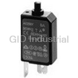
MINIATURISED SINGLE POLE THERMAL CIRCUIT BREAKER WITH PUSH-TO-RESET TEASE FREE, TRIP-FREE, SNAP ACTI...
MINIATURISED SINGLE POLE THERMAL CIRCUIT BREAKER WITH PUSH-TO-RESET TEASE FREE, TRIP-FREE, SNAP ACTI...
Circuit Breaker Thermal 1Pole 2A 240VAC/28VDC
Circuit Breaker Thermal 1Pole 4A 240VAC/28VDC
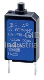
Circuit Breaker Thermal 1Pole 0.2A 240VAC/48VDC 104-PR-0.2A
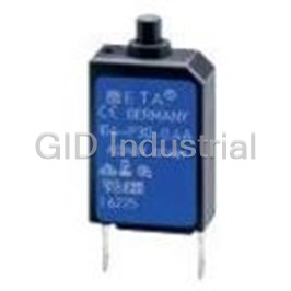
Circuit Breaker Thermal 1Pole 0.3A 240VAC/48VDC 104-PR-0.3A
Request a Quote

The quote request has been received
Close

Facing challenges or have inquiries? Feel free to contact us!
Call Us +1-469-283-2440
What they say about us
FANTASTIC RESOURCE
One of our top priorities is maintaining our business with precision, and we are constantly looking for affiliates that can help us achieve our goal. With the aid of GID Industrial, our obsolete product management has never been more efficient. They have been a great resource to our company, and have quickly become a go-to supplier on our list!
Bucher Emhart Glass
EXCELLENT SERVICE
With our strict fundamentals and high expectations, we were surprised when we came across GID Industrial and their competitive pricing. When we approached them with our issue, they were incredibly confident in being able to provide us with a seamless solution at the best price for us. GID Industrial quickly understood our needs and provided us with excellent service, as well as fully tested product to ensure what we received would be the right fit for our company.
Fuji
HARD TO FIND A BETTER PROVIDER
Our company provides services to aid in the manufacture of technological products, such as semiconductors and flat panel displays, and often searching for distributors of obsolete product we require can waste time and money. Finding GID Industrial proved to be a great asset to our company, with cost effective solutions and superior knowledge on all of their materials, it’d be hard to find a better provider of obsolete or hard to find products.
Applied Materials
CONSISTENTLY DELIVERS QUALITY SOLUTIONS
Over the years, the equipment used in our company becomes discontinued, but they’re still of great use to us and our customers. Once these products are no longer available through the manufacturer, finding a reliable, quick supplier is a necessity, and luckily for us, GID Industrial has provided the most trustworthy, quality solutions to our obsolete component needs.
Nidec Vamco
TERRIFIC RESOURCE
This company has been a terrific help to us (I work for Trican Well Service) in sourcing the Micron Ram Memory we needed for our Siemens computers. Great service! And great pricing! I know when the product is shipping and when it will arrive, all the way through the ordering process.
Trican Well Service
GO TO SOURCE
When I can't find an obsolete part, I first call GID and they'll come up with my parts every time. Great customer service and follow up as well. Scott emails me from time to time to touch base and see if we're having trouble finding something.....which is often with our 25 yr old equipment.
ConAgra Foods