

 Manufacturers
EAO 01-272.025
Description
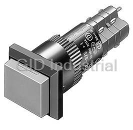
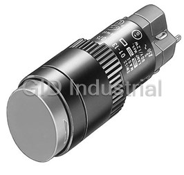
Switch Push Button N.O./N.C. 4PST Round Button 5A 250VAC 250VDC Maintained Contact Solder Panel Mount
01-272.025
Part Number
01-272.025
Price
Request Quote
Manufacturer
EAO
Lead Time
Request Quote
Category
Switches » Switch Push Button
Specifications
Manufacturer
EAO
Manufacturers Part #
01-272.025
Industry Aliases
01-272.025
Sub-Category
Push Button Switches
Factory Pack Quantity
1
Datasheet

Extracted Text
Edition 01/2016 HMI Components Series 01 Characteristics Functions Market segments The compact 16 mm Series 01 is The Series 01 incorporates the The EAO Series 01 is especially suited especially suited for: following functions: for applications in the segments: ■ ■ ■ Raised design Indicator Machinery and Automation ■ ■ Pushbutton Panel building ■ This series is ideally suited for combined Illuminated pushbutton use with Series 51. Please refer to the EAO website to obtain detailed information regarding this series www.products.eao.com Confi gure a product to your exact needs and request a quotation. Content 01 Overview Raised design Indicator 4 Illuminated pushbutton 6 Accessoires 10 Drawings 22 Technical data 23 Marking 25 Guidelines for use 26 Index 28 3 01 Raised design Indicator, IP 40 Equipment consisting of (schematic overview) 8 max. L1 Lens page 10 39 L Single-LED page 17 H 9 34 Actuator 46 3 Fixing nut Product can differ from the current configuration. Dimensions [mm] H = Universal terminal 2.0 x 0.5 mm, L = Solder terminal, Each Part Number listed below includes all the black L1 = Solder terminal 2.8 x 0.5 mm components shown in the 3D-drawing. To obtain a complete unit, please select the red com- 18min. 18x18mm/Ø18mm ponents from the pages shown. 24min. 18x24mm 10.4 +0.2 Ø16 0 Mounting cut-outs [mm] Diode 1N4007 Terminal Part No. Weight Indicator actuator, Front dimension 18 x 18 mm 1 Universal 2.0 x 0.5 mm 01-703.006 4 1 0.008 kg 2 Universal 2.0 x 0.5 mm 01-704.006 4 2 0.008 kg Solder 2.8 x 0.5 mm 01-050.002 3 0.006 kg Solder 01-050.005 3 0.006 kg Universal 2.0 x 0.5 mm 01-051.006 4 3 0.006 kg Indicator actuator, Front dimension 18 x 24 mm 1 Universal 2.0 x 0.5 mm 01-701.006 4 1 0.008 kg 2 Universal 2.0 x 0.5 mm 01-702.006 4 2 0.008 kg Solder 2.8 x 0.5 mm 01-040.002 3 0.006 kg Solder 01-040.005 3 0.006 kg Universal 2.0 x 0.5 mm 01-041.006 4 3 0.006 kg 4 18min. Ø2 Compo- nent layout Wiring diagram Raised design 01 Diode 1N4007 Terminal Part No. Weight Indicator actuator, Front dimension Ø 18 mm 1 Universal 2.0 x 0.5 mm 01-741.006 4 1 0.008 kg 2 Universal 2.0 x 0.5 mm 01-742.006 4 2 0.008 kg Solder 2.8 x 0.5 mm 01-030.002 3 0.006 kg Solder 01-030.005 3 0.006 kg Universal 2.0 x 0.5 mm 01-031.006 4 3 0.006 kg The component layouts you will find from page 22 a-(x1) 3(+) a-(x1) 3(+) 1(+) a-(x1) b+(x2) 4(-) b+(x2) 4(-) 2(-) b+(x2) Wiring diagram 1 Wiring diagram 2 Wiring diagram 3 5 Compo- nent layout Wiring diagram 01 Raised design Illuminated pushbutton, IP 40 Equipment consisting of (schematic overview) L1 8 max. 49 Lens page 10 H L Single-LED page 17 46 3 9 42 … 64.5 H1 Actuator 56.5 … 64 Product can differ from the current configuration. Dimensions [mm] H = Universal terminal 2.0 x 0.5 mm, Fixing nut H1 = Universal-Solder terminal, L = Solder terminal, L1 = Solder terminal 2.8 x 0.5 mm Each Part Number listed below includes all the black components shown in the 3D-drawing. Additional Information 18min. 18x18mm/Ø18mm To obtain a complete unit, please select the red com- ponents from the pages shown. • Material of contact Gold 24min. 18x24mm 10.4 +0.2 Ø16 0 Mounting cut-outs [mm] Switching system Contacts Diode 1N4007 Switching action Terminal Part No. Weight Illuminated pushbutton actuator, Front dimension 18 x 18 mm Low-level element 1 NC B Universal 2.0 x 0.5 mm 01-456.036 4 1 0.009 kg C Universal 2.0 x 0.5 mm 01-486.036 4 2 0.009 kg 1 NC + 1 NO B Universal 2.0 x 0.5 mm 01-453.036 4 3 0.009 kg C Universal 2.0 x 0.5 mm 01-483.036 4 4 0.009 kg 1 NO B Universal 2.0 x 0.5 mm 01-455.036 4 5 0.009 kg C Universal 2.0 x 0.5 mm 01-485.036 4 6 0.009 kg 2 NO B Universal 2.0 x 0.5 mm 01-451.036 4 9 0.009 kg C Universal 2.0 x 0.5 mm 01-481.036 4 10 0.009 kg Snap-action switching 1 NC + 1 NO 1 B Universal-Solder 01-709.0292 4 11 0.010 kg element C Universal-Solder 01-717.0292 4 12 0.010 kg 2 B Universal-Solder 01-710.0292 4 13 0.010 kg C Universal-Solder 01-718.0292 4 14 0.010 kg B Solder 01-151.0252 15 0.008 kg B Solder 2.8 x 0.5 mm 01-151.022 16 0.008 kg C Solder 01-281.0252 17 0.008 kg C Solder 2.8 x 0.5 mm 01-281.022 18 0.008 kg 2 NC + 2 NO 1 B Universal-Solder 01-711.0292 4 19 0.012 kg C Universal-Solder 01-719.0292 4 20 0.012 kg 6 18min. Ø2 Compo- nent layout Wiring diagram Raised design 01 Switching system Contacts Diode 1N4007 Switching action Terminal Part No. Weight Sprungschaltelement 2 Ö + 2 S 2 B Universal-Löt 01-712.0292 4 21 0.012 kg B Solder 01-152.0252 23 0.010 kg C Solder 01-282.0252 24 0.010 kg 3 NC + 3 NO B Solder 01-153.0252 25 0.012 kg C Solder 01-283.0252 26 0.012 kg 4 NC + 4 NO B Solder 01-154.0252 27 0.014 kg C Solder 01-284.0252 28 0.014 kg Illuminated pushbutton actuator, Front dimension 18 x 24 mm 1 NC + 1 NO B Universal 2.0 x 0.5 mm 01-423.036 4 3 0.009 kg C Universal 2.0 x 0.5 mm 01-463.036 4 4 0.009 kg 1 NO B Universal 2.0 x 0.5 mm 01-425.036 4 5 0.009 kg C Universal 2.0 x 0.5 mm 01-465.036 4 6 0.009 kg 2 NC B Universal 2.0 x 0.5 mm 01-422.036 4 7 0.009 kg C Universal 2.0 x 0.5 mm 01-462.036 4 8 0.009 kg 2 NO B Universal 2.0 x 0.5 mm 01-421.036 4 9 0.009 kg C Universal 2.0 x 0.5 mm 01-461.036 4 10 0.009 kg Snap-action switching 1 NC + 1 NO 1 B Universal-Solder 01-705.0292 4 11 0.010 kg element C Universal-Solder 01-713.0292 4 12 0.010 kg 2 B Universal-Solder 01-706.0292 4 13 0.010 kg C Universal-Solder 01-714.0292 4 14 0.010 kg B Solder 01-121.0252 15 0.008 kg B Solder 2.8 x 0.5 mm 01-121.022 16 0.008 kg C Solder 01-261.0252 17 0.008 kg C Solder 2.8 x 0.5 mm 01-261.022 18 0.008 kg 2 NC + 2 NO 1 B Universal-Solder 01-707.0292 4 19 0.012 kg C Universal-Solder 01-715.0292 4 20 0.012 kg 2 B Universal-Solder 01-708.0292 4 21 0.012 kg C Universal-Solder 01-716.0292 4 22 0.012 kg B Solder 01-122.0252 23 0.010 kg C Solder 01-262.0252 24 0.010 kg 3 NC + 3 NO B Solder 01-123.0252 25 0.012 kg C Solder 01-263.0252 26 0.012 kg 4 NC + 4 NO B Solder 01-124.0252 27 0.014 kg C Solder 01-264.0252 28 0.014 kg Switching system Contacts Diode 1N4007 Switching action Terminal Part No. Weight 7 Compo- Compo- nent layout nent layout Wiring dia- Wiring gram diagram 01 Raised design Illuminated pushbutton actuator, Front dimension Ø 18 mm 1 NC + 1 NO B Universal 2.0 x 0.5 mm 01-433.036 4 3 0.009 kg C Universal 2.0 x 0.5 mm 01-473.036 4 4 0.009 kg 1 NO B Universal 2.0 x 0.5 mm 01-435.036 4 5 0.009 kg C Universal 2.0 x 0.5 mm 01-475.036 4 6 0.009 kg 2 NC B Universal 2.0 x 0.5 mm 01-432.036 4 7 0.009 kg C Universal 2.0 x 0.5 mm 01-472.036 4 8 0.009 kg 2 NO B Universal 2.0 x 0.5 mm 01-431.036 4 9 0.009 kg C Universal 2.0 x 0.5 mm 01-471.036 4 10 0.009 kg Snap-action switching 1 NC + 1 NO 1 B Universal-Solder 01-743.0292 4 11 0.010 kg element 2 B Universal-Solder 01-744.0292 4 13 0.010 kg C Universal-Solder 01-748.0292 4 14 0.010 kg B Solder 01-131.0252 15 0.008 kg B Solder 2.8 x 0.5 mm 01-131.022 16 0.008 kg C Solder 01-271.0252 17 0.008 kg C Solder 2.8 x 0.5 mm 01-271.022 18 0.008 kg 2 B Universal-Solder 01-746.0292 4 21 0.012 kg C Universal-Solder 01-750.0292 4 22 0.012 kg B Solder 01-132.0252 23 0.010 kg C Solder 01-272.0252 24 0.010 kg 3 NC + 3 NO B Solder 01-133.0252 25 0.012 kg C Solder 01-273.0252 26 0.012 kg 4 NC + 4 NO B Solder 01-134.0252 27 0.014 kg C Solder 01-274.0252 28 0.014 kg Contacts: NC = Normally closed, NO = Normally open Switching action: B = Momentary, C = Maintain The component layouts you will find from page 22 1a- 1a- 13 a- 13 a- 1a- 1a- 2 2 4 4 b+ b+ 2b+ 2b+ 2b+ 2b+ Wiring diagram 1 Wiring diagram 2 Wiring diagram 3 Wiring diagram 4 Wiring diagram 5 Wiring diagram 6 1a 3 - 1a 3 - 13 a- 13 a- 1a 3 - 3(+) I 2 4 b+ 2 4 b+ 2b 4 + 2b 4 + 2 4b+ 4(-) Wiring diagram 7 Wiring diagram 8 Wiring diagram 9 Wiring diagram 10 Wiring diagram 11 8 Raised design 01 1a 3 - 3(+) 1a 3 - 3(+) 1(-) 1a 3 - 3(+) 1(-) 1x 3 1- I I I I 2 4b+ 4(-) 2 4b+ 4(-) 2(+) 2 4b+ 4(-) 2(+) 2 4x2+ Wiring diagram 12 Wiring diagram 13 Wiring diagram 14 Wiring diagram 15 1 3 a- 1 3 x1- 1a 3 - 1a 3 1 3 - 3(+) I I I I II 2 4 b+ 2 4 x2+ 2 4b+ 2 4b 2 4 + 4(-) Wiring diagram 16 Wiring diagram 17 Wiring diagram 18 Wiring diagram 19 1a 3 1 3 - 3(+) 1a 3 1 3 - 3(+) 1(-) 1a 3 1 3 - 3(+) 1(-) I II I II I II 2 4b 2 4 + 4(-) 2 4b 2 4 + 4(-) 2(+) 2 4b 2 4 + 4(-) 2(+) Wiring diagram 20 Wiring diagram 21 Wiring diagram 22 1 3 1 3 x1- 1 3 1 3 x1- 1 3 1 3 1 3 x1- I II I II I II III 2 4 2 4 x2+ 2 4 2 4 x2+ 2 4 2 4 2 4 x2+ Wiring diagram 23 Wiring diagram 24 Wiring diagram 25 1 3 1 3 1 3 x1- 1 3 1 3 1 3 1 3 x1- I II III I II III IV 2 4 2 4 2 4 x2+ 2 4 2 4 2 4 2 4 x2+ Wiring diagram 26 Wiring diagram 27 1 3 1 3 1 3 1 3 x1- I II III IV 2 4 2 4 2 4 2 4 x2+ Wiring diagram 28 9 01 Accessories Front Lens plastic Product attribute Dimension Lens Part No. Weight Lens plastic flat, illuminative 12.8 x 12.8 mm red transparent 01-985.2 0.001 kg orange transparent 01-985.3 0.001 kg yellow transparent 01-985.4 0.001 kg green transparent 01-985.5 0.001 kg blue transparent 01-985.6 0.001 kg colourless transparent 01-985.7 0.001 kg flat, illuminative, not suitable for film insert 12.8 x 12.8 mm red translucent 01-951.2 0.001 kg orange translucent 01-951.3 0.001 kg yellow translucent 01-951.4 0.001 kg green translucent 01-951.5 0.001 kg blue translucent 01-951.6 0.001 kg white translucent 01-951.9 0.001 kg flat, illuminative, less suitable for film insert 12.8 x 12.8 mm red transparent 01-975.2 0.001 kg yellow transparent 01-975.4 0.001 kg green transparent 01-975.5 0.001 kg colourless transparent 01-975.7 0.001 kg flat, non-illuminative 12.8 x 12.8 mm black opaque 01-951.0 0.001 kg grey opaque 01-951.8 0.001 kg Lens plastic flat, illuminative 12.8 x 18.8 mm red transparent 01-982.2 0.001 kg orange transparent 01-982.3 0.001 kg yellow transparent 01-982.4 0.001 kg green transparent 01-982.5 0.001 kg blue transparent 01-982.6 0.001 kg colourless transparent 01-982.7 0.001 kg flat, illuminative, not suitable for film insert 12.8 x 18.8 mm red translucent 01-901.2 0.001 kg orange translucent 01-901.3 0.001 kg yellow translucent 01-901.4 0.001 kg green translucent 01-901.5 0.001 kg blue translucent 01-901.6 0.001 kg white translucent 01-901.9 0.001 kg flat, illuminative, less suitable for film insert 12.8 x 18.8 mm red transparent 01-972.2 0.001 kg yellow transparent 01-972.4 0.001 kg green transparent 01-972.5 0.001 kg colourless transparent 01-972.7 0.001 kg flat, non-illuminative 12.8 x 18.8 mm black opaque 01-901.0 0.001 kg grey opaque 01-901.8 0.001 kg 10 Accessories 01 Product attribute Dimension Lens Part No. Weight Lens plastic flat, illuminative Ø 15.8 mm red transparent 01-983.2 0.001 kg orange transparent 01-983.3 0.001 kg yellow transparent 01-983.4 0.001 kg green transparent 01-983.5 0.001 kg blue transparent 01-983.6 0.001 kg colourless transparent 01-983.7 0.001 kg flat, illuminative, not suitable for film insert Ø 15.8 mm red translucent 01-931.2 0.001 kg orange translucent 01-931.3 0.001 kg yellow translucent 01-931.4 0.001 kg green translucent 01-931.5 0.001 kg blue translucent 01-931.6 0.001 kg white translucent 01-931.9 0.001 kg flat, illuminative, less suitable for film insert Ø 15.8 mm red transparent 01-973.2 0.001 kg yellow transparent 01-973.4 0.001 kg green transparent 01-973.5 0.001 kg colourless transparent 01-973.7 0.001 kg flat, non-illuminative Ø 15.8 mm black opaque 01-931.0 0.001 kg grey opaque 01-931.8 0.001 kg 11 01 Accessories Protective cover, IP 40 Additional Information 10 32 20min. 18x18mm • Hinged, with means for sealing 24min. 18x24mm • Front panel thickness reduced by 2 mm 20 14.5 12 30 +0.2 Ø16 0 Mounting cut-outs [mm] 24 11 Dimensions [mm] Product attribute Material Optics Dimension Part No. Weight Protective cover for button 18 x 18 mm with mounting cut-out Ø16 mm Plastic transparent 31-920 0.002 kg Protective cover for button 18 x 24 mm with mounting cut-out Ø16 mm Plastic transparent 18 x 24 mm 01-925 0.002 kg Front protective cap, IP 65 Additional Information 24min. 18x18mm • Two-part 30min. 18x24mm • Front panel thickness reduces by 1 mm 24 30 13 +0.2 Ø16 0 Dimensions [mm] Mounting cut-outs [mm] Dimension Mounting cut-out Material Colour Optics Part No. Weight Front protective cap 18 x 18 mm Ø 16 mm PE/Silicone colourless transparent 31-923 0.003 kg 18 x 24 mm Ø 16 mm PE/Silicone colourless transparent 31-924.2 0.003 kg 12 24 10.5 10.5 23.5 23.5 24 23.5 25.5 24min. 30min. Accessories 01 Protective guard Additional Information • Please note that bigger minimum distances are necessary 26 12 24 Dimensions [mm] Product attribute Dimension Material Colour Part No. Weight Protective guard narrow ends bent upwards, 18 x 26 mm Brass matt chrome 01-926 0.011 kg for button 18 x 24 mm with mounting cut-out Ø16 mm Protective guard broad sides bent upwards, 20 x 24 mm Brass matt chrome 01-927 0.011 kg for button 18 x 24 mm with mounting cut-out Ø16 mm 13 20 18 01 Accessories Blind plug 18min. 18x18mm/Ø18mm 24min. 18x24mm 10.4 +0.2 Ø16 0 Mounting cut-outs [mm] Dimension Material Colour Part No. Weight Blind plug 18 x 18 mm Plastic black 01-948.0 0.001 kg Blind plug 18 x 24 mm Plastic black 01-947.0 0.001 kg Blind plug Ø 18 mm Plastic black 01-949.0 0.001 kg 14 18min. Ø2 Accessories 01 Rear side PCB plug-in base Additional Information 2 9.8 • PCB plug-in base pins right-angle: With the ex- tendable mounting the distance between plug-in base and PCB can be varied up to 3 mm Ø16.4 4 3 4 9.6 6.2 17.9 1.5 9.8 12.9 4 Dimensions [mm] Product attribute Pins Terminal Part No. Weight PCB plug-in base for low level switching element axial PCB 31-940 3 0.002 kg PCB plug-in base for low level switching element right-angled PCB 31-941 1 0.004 kg PCB plug-in base for snap-action switching element 2.8 mm axial PCB 31-942 2 0.002 kg The component layouts you will find from page 22 15 17.8 17.9 Compo- nent layout 01 Accessories Flat receptacle Product attribute Part No. Weight Flat receptacle 2.0 x 0.5 mm plug-in terminal 31-945 0.001 kg Flat receptacle 2.8 x 0.5 mm plug-in terminal 31-946 0.001 kg Insulation sleeve Product attribute Part No. Weight Insulation sleeve for flat receptacle 2.0 mm 31-928 0.001 kg Insulation sleeve for flat receptacle 2.8 mm 31-929 0.001 kg Insulation sleeve cover plug-in terminals for snap-action switching element 2.8 mm 01-928 0.001 kg Terminal cover Part No. Weight Terminal cover for snap-action switching element 16 01-929 0.010 kg 16 Accessories 01 Illumination Single-LED, T5.5 Additional Information • For LED element fitting information see «Applica- 30 max. tion guidelines» • Due to high surface temperatures, the series + resistor must not be soldered directly to the termi- nals of the equipment (use a terminal plate) • When using AC/DC types with AC operation, slight flickering can occure • Luminous intensity data of the LEDs on direct voltage • Electrical and optical data are measured at 25 °C Dimensions [mm] • The specified versions are built with a protection diode (halve wave rectifier) in series and the LED • Luminosity and wave length variations caused by LED manufacturing processes may cause slight differences regarding the illumination • For supply voltages above 48 V, a voltage reduc- tion element (external series resistor or transfor- mer) must be used LED colour Operating voltage Operation current Lumi. intensity Dom. wavelength Part No. Weight Single-LED Single-LED red 6 VDC +10 % 15 mA±15 % 350 mcd 630 nm 10-2106.3142 0.001 kg 12 VAC/DC +10 % 7/14 mA±15 % 330 mcd 630 nm 10-2109.1062 0.001 kg 24 VAC/DC +10 % 7/14 mA±15 % 330 mcd 630 nm 10-2112.1062 0.001 kg 28 VAC/DC +10 % 7/14 mA±15 % 330 mcd 630 nm 10-2113.1062 0.001 kg 48 VAC/DC +10 % 4/8 mA±15 % 200 mcd 630 nm 10-2119.1042 0.001 kg Single-LED yellow 6 VDC +10 % 15 mA±15 % 300 mcd 587 nm 10-2106.3144 0.001 kg 12 VAC/DC +10 % 7/14 mA±15 % 280 mcd 587 nm 10-2109.1064 0.001 kg 24 VAC/DC +10 % 7/14 mA±15 % 280 mcd 587 nm 10-2112.1064 0.001 kg 28 VAC/DC +10 % 7/14 mA±15 % 280 mcd 587 nm 10-2113.1064 0.001 kg 48 VAC/DC +10 % 4/8 mA±15 % 180 mcd 587 nm 10-2119.1044 0.001 kg Single-LED green 6 VDC +10 % 7 mA±15 % 1050 mcd 525 nm 10-2106.3145 0.001 kg 12 VAC/DC +10 % 4/7 mA±15 % 1050 mcd 525 nm 10-2109.1065 0.001 kg 24 VAC/DC +10 % 4/7 mA±15 % 1050 mcd 525 nm 10-2112.1065 0.001 kg 28 VAC/DC +10 % 4/7 mA±15 % 1050 mcd 525 nm 10-2113.1065 0.001 kg 48 VAC/DC +10 % 2/4 mA±15 % 600 mcd 525 nm 10-2119.1045 0.001 kg Single-LED blue 6 VDC +10 % 15 mA±15 % 680 mcd 470 nm 10-2106.3146 0.001 kg 12 VAC/DC +10 % 7/14 mA±15 % 650 mcd 470 nm 10-2109.1066 0.001 kg 24 VAC/DC +10 % 7/14 mA±15 % 650 mcd 470 nm 10-2112.1066 0.001 kg 28 VAC/DC +10 % 7/14 mA±15 % 650 mcd 470 nm 10-2113.1066 0.001 kg 48 VAC/DC +10 % 4/8 mA±15 % 400 mcd 470 nm 10-2119.1046 0.001 kg 17 Ø6 max. 01 Accessories LED colour Operating voltage Operation current Lumi. intensity Dom. wavelength Part No. Weight Single-LED white 6 VDC +10 % 6 mA ±15 % 900 mcd x0.31/y0.32 nm 10-2106.3149 0.001 kg 12 VAC/DC +10 % 3/6 mA ±15 % 900 mcd x0.31/y0.32 nm 10-2109.1069 0.001 kg 24 VAC/DC +10 % 2.5/5 mA ±15 % 750 mcd x0.31/y0.32 nm 10-2112.1069 0.001 kg 28 VAC/DC +10 % 2.5/5 mA ±15 % 750 mcd x0.31/y0.32 nm 10-2113.1069 0.001 kg 48 VAC/DC +10 % 2/4 mA ±15 % 600 mcd x0.31/y0.32 nm 10-2119.1049 0.001 kg Filament lamp, T5.5 Operating voltage Operation current Part No. Weight Filament lamp 6 VAC/DC 200 mA 10-1106.1369 0.001 kg 12 VAC/DC 50 mA 10-1109.1279 0.001 kg 12 VAC/DC 100 mA 10-1109.1329 0.001 kg 24 VAC/DC 25 mA 10-1112.1199 0.001 kg 24 VAC/DC 50 mA 10-1112.1279 0.001 kg 28 VAC/DC 40 mA 10-1113.1249 0.001 kg 30 VAC/DC 40 mA 10-1114.1249 0.001 kg 36 VAC/DC 35 mA 10-1116.1229 0.001 kg 48 VAC/DC 25 mA 10-1119.1199 0.001 kg Series resistor Additional Information • For lamp voltage reduction • Only for filament lamp 48 VAC, 25 mA • Keep to the country specific safety instructions • Due to high surface temperatures, the series resistor must not be soldered directly to the termi- nals of the equipment (use a terminal plate) Operating voltage Resistance Part No. Weight Series resistor 110 VAC 2.7 kOhm 02-904.0 0.003 kg 125 VAC 3.3 kOhm 02-904.1 0.003 kg 145 VAC 4.7 kOhm 02-904.3 0.003 kg 240 VAC 10 kOhm 02-904.7 0.003 kg 18 Accessories 01 Terminal plate empty Additional Information • For fitting with series resistors Product attribute Dimension Part No. Weight Terminal plate empty 5 spaces 62.5 x 60 x 15 mm 02-912.1 0.025 kg 10 spaces 125 x 60 x 15 mm 02-912.2 0.045 kg 15 spaces 187.6 x 60 x 15 mm 02-912.3 0.090 kg 20 spaces 250 x 60 x 15 mm 02-912.4 0.095 kg 19 01 Accessories Mounting Lens remover Part No. Weight Lens remover 02-905 0.011 kg Lamp remover Additional Information p Caution: A switching process might be released when replacing the lamp Part No. Weight Lamp remover 02-906 0.002 kg Mounting tool Additional Information • For tightening or loosening of the fixing nut Part No. Weight Mounting tool 01-907 0.020 kg 20 Accessories 01 Dressing tool Additional Information • For aligning buttons Part No. Weight Dressing tool 01-906 0.030 kg 21 01 Drawings Drawings Montagestege 3.81 3.81 ausziehbar b a 3 1 42 3 1 Ø2.1 Bohrung Taste b a für eine eventuelle +0.1 Zentralbefestigung 42 Ø1.0 0 mit M2 Schraube alle Bohrungen 9.6 17.9 15.24 Ø1.0 alle Bohrungen Bohrplan (Lötseite) 1.27 5 x 2.54 1.27 Component layout 1 Component layout 2 3.81 3.81 Ø1.0 alle Bohrungen Ø2.1 Bohrung für eine eventuelle Zentralbefestigung mit M2 Schraube 12.7 Component layout 3 Anschlüsse (rückseitig) Bohrplan (Lötseite) 7.62 Ø18 mm 18 x 18 mm 18 x 24 mm 3.81 Verdrehschutz nur 18 x 24 mm Ø1.0 alle Bohrungen Component layout 4 22 1 3 ab 24 1 3 4 3 ab 0.85 24 5.08 10.16 1 3 ab 24 9 1.27 1.27 7.62 17.9 7.62 5.08 2.54 7.62 10.16 10.16 Technical data 01 Actuator with snap-action switching element Switching system Rated voltage Self-cleaning, double-break, snap action switching system (with 250 VAC/VDC contact gap 2 x 0.5 mm). Rated current 1 Normally closed or 1 Normally open contact per element. 5 A Snap-action switching elements with soldering terminals at the sides: Up to 4 switching element can be on a pushbutton (max. 4 Contact resistance Normally closed and 4 Normally open contacts). Starting value (initial) ≤50 mΩ Snap-action switching element with axial plug-in terminals 2.8 mm stachable, only 1 switching element can be on a pushbutton. Conventional free air thermal current 5 A The maximum current in continuous operation and at ambient Material temperature not exceeding the quoted maximum values. Material of contact Switch rating Gold plated silver 250 VAC, 5 A (cosφ 1) 250 VAC, 3 A (cosφ 0,3) Switch housing Axial plug-in-/soldering terminal 2.8 mm: Switch rating AC (cosφ 0,7) Diallylphthalate (DAP), Polyamide (PA66), Polysulfone (PSU), heat-resistant and self-extinguishing Voltage 125 VAC 250 VAC Soldering terminal: Ultramide (PA 6.6) Current 3 A 2 A Actuator housing Switch rating DC (inductive) L:R = 30 ms Polyphenylene (PPO), self-extinguishing Voltage 24 VDC 60 VDC 110 VDC 220 VDC Current 2 A 0.7 A 0.2 A 0.1 A Mechanical characteristics Electric strength Terminals 2500 VAC, 50 Hz, 1 min. between all terminals and earth, as per Snap-action switching element with tinned soldering terminals at IEC 60512-2-11 the sides: Max. wire diameter 2 wires à 1.2 mm Protection class Max. wire cross-section of stranded cable 1 x 1 mm² II Snap-action switching element with axial plug-in terminals, which can also be used as soldering terminals: Plug-in terminal 2.8 x 0.5 mm Environmental conditions Soldering terminal: Storage temperature Max. wire diameter 2 wire of 1 mm² -40 °C ... +85 °C Max. wire cross-section of stranded cable 2 x 0.75 mm² or 1 x 1 mm² Service temperature -25 °C ... +55 °C Tightening torque For indicators and illuminated pushbuttons mounted as a block, for fixing nut max. 25 Ncm make sure the heat can escape freely. Actuating force Protection degree 2 N ... 5.5 N, depending on the number of switching elements Front P 40 IP 67 with front protective cap Actuating travel 3 mm Shock resistance (Single impacts, semi-sinusoidal) Rebound time 15 g for 11 ms, as per IEC 60512-4-3, IEC 60068-2-27 ≤5ms Vibration resistance Mechanical lifetime (sinusoidal) Momentary action 2 million cycles of operation 10 g at 0-2000 Hz, amplitude 1.5 mm, as per IEC 60512-4-4, Maintained action 1 million cycles of operation IEC 60068-2-6 Electrical characteristics Standards IEC 61058, EN 61058 23 01 Technical data Approvals Approbations CB (IEC 61058) CSA ENEC (EN 61058) Germanischer Lloyd UL Declaration of conformity CE Actuator with low level switching element Switching system Mechanical lifetime This low level switching element was designed for switching low Momentary action 5 million cycles of operation powers in electronic circuits. The mechanism assures reliable Maintained action 1 million cycles of operation switching of loads ranging from a few μA / μV up to 100 mA / 42 VAC/DC. Single-break momentary contact, as normally open or normally Electrical characteristics closed with 4 independent points of contact. 2 momentary con- tacts per switching element; combination of normally open and Standards normally closed is possible. EN 61058 Special features are the long life, extremely short rebound time and stable contact resistance. Contact resistance Starting value (initial) ≤50 mΩ Switch rating Material 10 μA, 100 μV to 100 mA at 42 VAC/VDC Material of contact Electric strength Gold plated 2500 VAC, 50 Hz, 1 min. between all terminals and earth, as per IEC 60512-2-11 Switch housing Polysulfone (PSU), heat-resistant and self-extinguishing Protection class II Actuator housing Polyphenylene (PPO), self-extinguishing Environmental conditions Mechanical characteristics Storage temperature -40 °C ... +85 °C Terminals The universal terminals permit these units to be mounted on Service temperature printed circuit boards (PCB). These terminals can also be used as -25 °C ... +55 °C soldering or plug-in terminals. For indicators and illuminated pushbuttons mounted as a block, For these terminals we can also supply a plug-in base which, make sure the heat can escape freely. when soldered on to the board, enables the switch to be plugged in. Protection degree Soldering terminal: Front P 40 Max. wire diameter 2 wires à 0.8 mm IP 67 with front protective cap Max. wire cross-section of stranded cable 1x 0.75 mm² Shock resistance Plug-in terminal: 2.0 x 0.5 mm (Single impacts, semi-sinusoidal) 15 g for 11 ms, as per IEC 60512-4-3, IEC 60068-2-27 Actuating force 3 N ... 3,5 N Climate resistance Standard condition, as per IEC 60068-2-3 and 2-30 Actuating travel Changing condition, as per IEC 60068-2-14 and 2-33 3 mm Rebound time Typ. <100 μs EAO reserves the right to alter specifications without further notice. 24 Marking 01 General notes 1. Engraving 3. Film inserts In addition to the most commonly used world languages, in Instead of using engraving the lenses can be fitted with transpa- DIN1451-3 close spacing, other typefaces are available as rent film inserts, as an alternative. For this purpose, though, it is Scandinavian, Slavic, Greek, Russian and Polish. Red, blue and advisible to use transparent lenses. In the case of use of a smoke- black lenses are filled with white colour. Other colour lenses black lens the fitted film becomes readable only if the lamp is on. are filled in black. Standard height of letters is 2 mm. If the height To insert the film, the feet of the lens holder have to be pushed is not specified, we will supply 2 mm engraved letters. together far enough to enable the lens to be lift off easily. The film thickness is 0.2 mm. 2. Hot stamping Important: Consider pushbutton mounting orientation befor For larger series it is worth considering markings by means of specifying engraving characters! hot stamping. We will pleased to advise you. For letters and figures, typefaces with 2.5 mm, 3 mm and 4 mm are available. All dimensions in mm Number of capital Number of small letters per line letters per line Front size (Lens) Film insert max. size Height of letters h Number of lines (target value) (target value) Image 18 x 18 (12.8 x 12.8) 10.2 x 10.2 2.5 3 6 – 7 7 B3 3.0 2 5 – 6 6 B3 4.0 2 4 4 B3 5.0 1 3 3 – 4 B3 6.0 1 2 – 3 3 B3 8.0 1 2 2 B3 18 x 24 (12.8 x 18.8) 10.2 x 16.2 2.5 3 10 10 – 11 B1 2.5 4 6 – 7 7 B2 3.0 2 8 – 9 9 B3 3.0 4 5 – 6 6 B4 4.0 2 6 6 – 7 B2 4.0 3 4 4 B1 5.0 1 5 5 – 6 B2 5.0 2 3 3 – 4 B1 6.0 1 4 4 – 5 B2 6.0 1 2 – 3 3 B1 8.0 1 3 3 – 4 B2 8.0 1 2 2 B2 Ø 18 (Ø 15.8) Ø 12.8 2.5 3 6 6 B4 3.0 2 5 6 B4 4.0 2 3 4 B4 5.0 1 2 3 B4 6.0 1 2 2 B4 8.0 1 2 2 B4 B1 B2 B3 B4 Film AB AB AB AB abc abc abc abc 25 h 01 Application guidelines Suppressor circuits When switching inductive loads such as relays, DC motors, and The free-wheeling diode should be chosen so that the reverse DC solenoids, it is always important to absorb surges (e. g. with a breakdown voltage is greater than the voltage driving the induc- diode) to protect the contacts. When these inductive loads are tive load. The DC blocking voltage (VR) of the free-wheeling diode switched off, a counter emf can severely damage switch contacts can be found in the datasheet of a diode. The forward current and greatly shorten lifetime. should be equal or greater than the maximum current flowing through the load. Fig. 1 shows an inductive load with a free-wheeling diode con- nected in parallel. This free-wheeling diode provides a path for the To get an efficient protection, the free-wheeling diode must inductor current to flow when the current is interrupted by the be connected as close as possible to the inductive load! switch. Without this free-wheeling diode, the voltage across the coil will be limited only by dielectric breakdown voltages of the circuit or parasitic elements of the coil. This voltage can be kilo- volts in amplitude even when nominal circuit voltages are low (e. g. 12 VDC) see Fig. 2. Counter EMF Switching with inductive load over load without free-wheeling diode Fig. 1 Fig. 2 Switch ON OFF 0 + Free-wheeling Inductive Several hundred VDC _ diode load to several di __ e = L thousend volts dt LED polarity When fitting the LED elements the polarity has to correspond with the respective terminals, (+) goes to +. +X2 (+X2) (-X1) 26 Application guidelines 01 Diode element for lamp check When indicators and illuminated pushbuttons equipped with diodes, the user is able to perform a lamp check or wire an alarm circuit simply with a considerable saving of space. Lamp check Lamp check with blocking diodes Alarm circuit from fault annunciation system Lamp check and alarm circuit Lamp check and alarm circuit with only one diode and AC voltage LK = Lamp control 27 01 Index Index from Part No. Part No. Page Part No. Page Part No. Page 01-030.002 ................ 5 01-715.0292 .............. 7 02-904.1 .................. 18 01-030.005 ................ 5 01-716.0292 .............. 7 02-904.3 .................. 18 01-031.006 ................ 5 01-717.0292 .............. 6 02-904.7 .................. 18 01-040.002 ................ 4 01-718.0292 .............. 6 02-905 ..................... 20 01-040.005 ................ 4 01-719.0292 .............. 6 02-906 ..................... 20 01-041.006 ................ 4 01-741.006 ................ 5 02-912.1 .................. 19 01-050.002 ................ 4 01-742.006 ................ 5 02-912.2 .................. 19 01-050.005 ................ 4 01-743.0292 .............. 8 02-912.3 .................. 19 01-051.006 ................ 4 01-744.0292 .............. 8 02-912.4 .................. 19 01-121.022 ................ 7 01-746.0292 .............. 8 10-1106.1369 .......... 18 01-121.0252 .............. 7 01-748.0292 .............. 8 10-1109.1279 .......... 18 01-122.0252 .............. 7 01-750.0292 .............. 8 10-1109.1329 .......... 18 01-123.0252 .............. 7 01-901.0 .................. 10 10-1112.1199 .......... 18 01-124.0252 .............. 7 01-901.2 .................. 10 10-1112.1279 .......... 18 01-131.022 ................ 8 01-901.3 .................. 10 10-1113.1249 .......... 18 01-131.0252 .............. 8 01-901.4 .................. 10 10-1114.1249 .......... 18 01-132.0252 .............. 8 01-901.5 .................. 10 10-1116.1229 .......... 18 01-133.0252 .............. 8 01-901.6 .................. 10 10-1119.1199 .......... 18 01-134.0252 .............. 8 01-901.8 .................. 10 10-2106.3142 .......... 17 01-151.022 ................ 6 01-901.9 .................. 10 10-2106.3144 .......... 17 01-151.0252 .............. 6 01-906 ..................... 21 10-2106.3145 .......... 17 01-152.0252 .............. 7 01-907 ..................... 20 10-2106.3146 .......... 17 01-153.0252 .............. 7 01-925 ..................... 12 10-2106.3149 .......... 18 01-154.0252 .............. 7 01-926 ..................... 13 10-2109.1062 .......... 17 01-261.022 ................ 7 01-927 ..................... 13 10-2109.1064 .......... 17 01-261.0252 .............. 7 01-928 ..................... 16 10-2109.1065 .......... 17 01-262.0252 .............. 7 01-929 ..................... 16 10-2109.1066 .......... 17 01-263.0252 .............. 7 01-931.0 .................. 11 10-2109.1069 .......... 18 01-264.0252 .............. 7 01-931.2 .................. 11 10-2112.1062 .......... 17 01-271.022 ................ 8 01-931.3 .................. 11 10-2112.1064 .......... 17 01-271.0252 .............. 8 01-931.4 .................. 11 10-2112.1065 .......... 17 01-272.0252 .............. 8 01-931.5 .................. 11 10-2112.1066 .......... 17 01-273.0252 .............. 8 01-931.6 .................. 11 10-2112.1069 .......... 18 01-274.0252 .............. 8 01-931.8 .................. 11 10-2113.1062 .......... 17 01-281.022 ................ 6 01-931.9 .................. 11 10-2113.1064 .......... 17 01-281.0252 .............. 6 01-947.0 .................. 14 10-2113.1065 .......... 17 01-282.0252 .............. 7 01-948.0 .................. 14 10-2113.1066 .......... 17 01-283.0252 .............. 7 01-949.0 .................. 14 10-2113.1069 .......... 18 01-284.0252 .............. 7 01-951.0 .................. 10 10-2119.1042 .......... 17 01-421.036 ................ 7 01-951.2 .................. 10 10-2119.1044 .......... 17 01-422.036 ................ 7 01-951.3 .................. 10 10-2119.1045 .......... 17 01-423.036 ................ 7 01-951.4 .................. 10 10-2119.1046 .......... 17 01-425.036 ................ 7 01-951.5 .................. 10 10-2119.1049 .......... 18 01-431.036 ................ 8 01-951.6 .................. 10 31-920 ..................... 12 01-432.036 ................ 8 01-951.8 .................. 10 31-923 ..................... 12 01-433.036 ................ 8 01-951.9 .................. 10 31-924.2 .................. 12 01-435.036 ................ 8 01-972.2 .................. 10 31-928 ..................... 16 01-451.036 ................ 6 01-972.4 .................. 10 31-929 ..................... 16 01-453.036 ................ 6 01-972.5 .................. 10 31-940 ..................... 15 01-455.036 ................ 6 01-972.7 .................. 10 31-941 ..................... 15 01-456.036 ................ 6 01-973.2 .................. 11 31-942 ..................... 15 01-461.036 ................ 7 01-973.4 .................. 11 31-945 ..................... 16 01-462.036 ................ 7 01-973.5 .................. 11 31-946 ..................... 16 01-463.036 ................ 7 01-973.7 .................. 11 01-465.036 ................ 7 01-975.2 .................. 10 01-471.036 ................ 8 01-975.4 .................. 10 01-472.036 ................ 8 01-975.5 .................. 10 01-473.036 ................ 8 01-975.7 .................. 10 01-475.036 ................ 8 01-982.2 .................. 10 01-481.036 ................ 6 01-982.3 .................. 10 01-483.036 ................ 6 01-982.4 .................. 10 01-485.036 ................ 6 01-982.5 .................. 10 01-486.036 ................ 6 01-982.6 .................. 10 01-701.006 ................ 4 01-982.7 .................. 10 01-702.006 ................ 4 01-983.2 .................. 11 01-703.006 ................ 4 01-983.3 .................. 11 01-704.006 ................ 4 01-983.4 .................. 11 01-705.0292 .............. 7 01-983.5 .................. 11 01-706.0292 .............. 7 01-983.6 .................. 11 01-707.0292 .............. 7 01-983.7 .................. 11 01-708.0292 .............. 7 01-985.2 .................. 10 01-709.0292 .............. 6 01-985.3 .................. 10 01-710.0292 .............. 6 01-985.4 .................. 10 01-711.0292 .............. 6 01-985.5 .................. 10 01-712.0292 .............. 7 01-985.6 .................. 10 01-713.0292 .............. 7 01-985.7 .................. 10 01-714.0292 .............. 7 02-904.0 .................. 18 28
Frequently asked questions
How does Electronics Finder differ from its competitors?

Is there a warranty for the 01-272.025?
Which carrier will Electronics Finder use to ship my parts?
Can I buy parts from Electronics Finder if I am outside the USA?
Which payment methods does Electronics Finder accept?
Why buy from GID?

Quality
We are industry veterans who take pride in our work

Protection
Avoid the dangers of risky trading in the gray market

Access
Our network of suppliers is ready and at your disposal

Savings
Maintain legacy systems to prevent costly downtime

Speed
Time is of the essence, and we are respectful of yours
Related Products
Switch Push Button N.O./N.C. DPST Rectangular Button 5A 250VAC Momentary Contact Solder Panel Mount ...
Switch Push Button N.O./N.C. DPST Rectangular Button 5A 250VAC 250VDC Momentary Contact Solder Panel...
Switch Push Button N.O./N.C. DPST Round Button 5A 250VAC Momentary Contact Solder Panel Mount 01-131...
Switch Push Button N.O./N.C. DPST Round Button 5A 250VAC 250VDC Momentary Contact Solder Panel Mount...
Switch Push Button N.O./N.C. DPST Square Button 5A 250VAC Momentary Contact Solder Panel Mount 01-15...
Switch Push Button N.O./N.C. DPST Rectangular Button 5A 250VAC Maintained Contact Solder Panel Mount...
Request a Quote

The quote request has been received
Close

Facing challenges or have inquiries? Feel free to contact us!
Call Us +1-469-283-2440
What they say about us
FANTASTIC RESOURCE
One of our top priorities is maintaining our business with precision, and we are constantly looking for affiliates that can help us achieve our goal. With the aid of GID Industrial, our obsolete product management has never been more efficient. They have been a great resource to our company, and have quickly become a go-to supplier on our list!
Bucher Emhart Glass
EXCELLENT SERVICE
With our strict fundamentals and high expectations, we were surprised when we came across GID Industrial and their competitive pricing. When we approached them with our issue, they were incredibly confident in being able to provide us with a seamless solution at the best price for us. GID Industrial quickly understood our needs and provided us with excellent service, as well as fully tested product to ensure what we received would be the right fit for our company.
Fuji
HARD TO FIND A BETTER PROVIDER
Our company provides services to aid in the manufacture of technological products, such as semiconductors and flat panel displays, and often searching for distributors of obsolete product we require can waste time and money. Finding GID Industrial proved to be a great asset to our company, with cost effective solutions and superior knowledge on all of their materials, it’d be hard to find a better provider of obsolete or hard to find products.
Applied Materials
CONSISTENTLY DELIVERS QUALITY SOLUTIONS
Over the years, the equipment used in our company becomes discontinued, but they’re still of great use to us and our customers. Once these products are no longer available through the manufacturer, finding a reliable, quick supplier is a necessity, and luckily for us, GID Industrial has provided the most trustworthy, quality solutions to our obsolete component needs.
Nidec Vamco
TERRIFIC RESOURCE
This company has been a terrific help to us (I work for Trican Well Service) in sourcing the Micron Ram Memory we needed for our Siemens computers. Great service! And great pricing! I know when the product is shipping and when it will arrive, all the way through the ordering process.
Trican Well Service
GO TO SOURCE
When I can't find an obsolete part, I first call GID and they'll come up with my parts every time. Great customer service and follow up as well. Scott emails me from time to time to touch base and see if we're having trouble finding something.....which is often with our 25 yr old equipment.
ConAgra Foods