

 Manufacturers
EAO 10-2601.3172S
Description
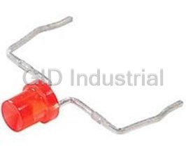
Standard LEDs - Through Hole Single LED 3mm Red 20mA 2VDC
Part Number
10-2601.3172S
Price
Request Quote
Manufacturer
EAO
Lead Time
Request Quote
Category
Optoelectronics and Displays » Switch Indicators
Specifications
Manufacturer
EAO
Manufacturers Part #
10-2601.3172S
Industry Aliases
10-2601.3172S
Sub-Categories
Switch Indicators
Factory Pack Quantity
1
Datasheet

Extracted Text
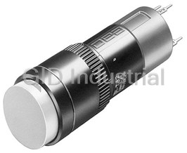
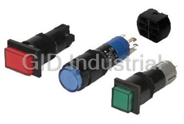
Edition 09/20166 HMI Components Series 70 Characteristics Functions Market segments The Series 70 consists of special short The Series 70 incorporates the The EAO Series 70 is especially suited stroke pushbuttons for use with following functions: for applications in the segments: membrane keyboards. It is particularly ■ ■ suited for: Indicator Machinery and Automation ■ ■ Pushbutton Medicinal technology ■ ■ ■ PCBs Illuminated pushbutton Laboratory and measuring equipment The use of single LEDs ensures that the entire control panel is very well illuminated. The module is offered in six colours and in a round or square design. Please refer to the EAO website to obtain detailed information regarding this series www.products.eao.com Confi gure a product to your exact needs and request a quotation. Content 70 Overview PCB pushbuttons Illumination element 4 Switching element without illumination 5 Switching element with illumination 6 Accessories 7 Drawings 10 Technical data 11 Application guidelines 13 Index 15 3 0.8 x 0.8 70 PCB pushbuttons Illumination element Equipment consisting of (schematic overview) Lens page 7 LED Illumination ele- ment 12.5 Each Part Number listed below includes all the black Product can differ from the current configuration. Dimensions components shown in the 3D-drawing. To obtain a complete unit, please select the red com- Additional Information ponents from the pages shown. • The customer has to decide what series resistor shall be used to the LED • Dimensions with fitted lens see details «Lens» • Luminosity and wave length variations caused by LED manufacturing processes may cause slight differences regarding the illumination LED colour Forward voltage typ. Lumi. intensity Dom. wavelength Terminal Part No. Weight Illumination element Single-LED red 2.0 VDC @ 20 mA 160 mcd 625 nm PCB 70-820.2S 3 2 0.001 kg Single-LED green 3.2 VDC @ 20 mA 650 mcd 525 nm PCB 70-820.5S 3 2 0.001 kg Illumination element PCB 92-800.042 1 0.001 kg The component layouts you will find from page 10 ++ – + – Wiring diagram 1 Wiring diagram 2 4 16.8 green red or yellow 1.6 6.35 4 5.7 Compo- nent layout Wiring diagram PCB pushbuttons 70 Switching element without illumination 9 Equipment consisting of (schematic overview) 3.5 3.5 1 Spacing cap page 8 Switching ele- ment Each Part Number listed below includes all the black 4.3 1.5 5 components shown in the 3D-drawing. 12 x 12 To obtain a complete unit, please select the red com- 1.2 3 ponents from the pages shown. Product can differ from the current configuration. Additional Information • Contact normally open 3 • Switching action momentary 4.5 3.6 • Dimensions with fitted spacing cap see details 1 1.8 «Spacing cap» 2 4 3 1 4 5.08 7.5 12.8 x 12.8 Dimensions Product attribute Contact material Terminal Part No. Weight Switching element without illumination without spacing cap Silver PCB 70-100.0 2 2 0.001 kg Switching element without illumination without spacing cap Silver PCB 70-101.0 2 2 0.001 kg Switching element without illumination without spacing cap Gold-plated silver PCB 70-201.0 1 1 0.001 kg The component layouts you will find from page 10 34 34 12 12 Wiring diagram 1 Wiring diagram 2 5 16.8 12.5 Ø1.6 12.5 3 x 3 3.8 x 3.8 Ø7.9 3.8 x 3.8 Compo- nent layout Wiring diagram 16.8 70 PCB pushbuttons Switching element with illumination Ø8 Equipment consisting of (schematic overview) Lens page 7 12.5 1 LED 1 2 Switching ele- 3 4 ment Each Part Number listed below includes all the black Product can differ from the current configuration. components shown in the 3D-drawing. Dimensions To obtain a complete unit, please select the red com- Additional Information ponents from the pages shown. • Contact normally open • Switching action momentary • The customer has to decide what series resistor shall be used to the LED • Luminosity and wave length variations caused by LED manufacturing processes may cause slight differences regarding the illumination • Dimensions with fitted lens see details «Lens» LED colour Forward voltage typ. Lumi. intensity Dom. wavelength Terminal Part No. Weight Switching element with illumination Single-LED red 2.0 VDC @ 20 mA Gold 160 mcd 625 nm PCB 70-220.2S 4 3 0.001 kg Single-LED yellow 2.9 VDC @ 20 mA Gold 600 mcd 580 nm PCB 70-220.4S 4 3 0.001 kg Single-LED green 3.2 VDC @ 20 mA Gold 650 mcd 525 nm PCB 70-220.5S 4 3 0.001 kg Single-LED blue 3.0 VDC @ 20 mA Gold 250 mcd 467 nm PCB 70-220.6S 4 3 0.001 kg Single-LED white 3.2 VDC @ 20 mA Gold 500 mcd x=0.3/y=0.3 PCB 70-220.9S 4 3 0.001 kg Switching element with illumination Gold PCB 92-851.342 4 1 0.001 kg The component layouts you will find from page 10 34 – 34 + 34 ++ 12 12 12 – Wiring diagram 1 Wiring diagram 2 Wiring diagram 3 6 green red or yellow Contact material 5.08 3.6 4 10.16 5.7 12.5 9.3 Compo- nent layout Wiring diagram Accessories 70 Front Lens Front dimensions R 12.4 x 12.4 R1.5 15.4 x 15.4 R2.9 19.05 x 19.05 R2.9 Ø12.4 – Ø15.4 – Dimensions Lens Part No. Weight Lens, Front dimension 19.05 x 19.05 mm Plastic white translucent 70-920.9 0.001 kg Lens, Front dimension 15.4 x 15.4 mm Plastic red translucent 70-921.2 0.001 kg Plastic orange translucent 70-921.3 0.001 kg Plastic yellow translucent 70-921.4 0.001 kg Plastic green translucent 70-921.5 0.001 kg Plastic blue translucent 70-921.6 0.001 kg Plastic white translucent 70-921.9 0.001 kg Lens, Front dimension 12.4 x 12.4 mm Plastic red translucent 70-922.2 0.001 kg Plastic orange translucent 70-922.3 0.001 kg Plastic yellow translucent 70-922.4 0.001 kg Plastic green translucent 70-922.5 0.001 kg Plastic blue translucent 70-922.6 0.001 kg Plastic white translucent 70-922.9 0.001 kg Lens, Front dimension Ø 15.4 mm Plastic red translucent 70-911.2 0.001 kg Plastic orange translucent 70-911.3 0.001 kg Plastic yellow translucent 70-911.4 0.001 kg Plastic green translucent 70-911.5 0.001 kg Kunststoff weiss transluzent 70-911.9 0.001 kg 7 13.2 3.2 1 Front- dimensions 70 Accessories Lens Part No. Weight Lens, Front dimension Ø 12.4 mm Plastic red translucent 70-912.2 0.001 kg Plastic orange translucent 70-912.3 0.001 kg Plastic yellow translucent 70-912.4 0.001 kg Plastic green translucent 70-912.5 0.001 kg Plastic white translucent 70-912.9 0.001 kg Spacing cap 6 20/20/19.05 min. H=9/13/22.5 16/16/15 18 min. H=18.9 14 Dimensions Product attribute Part No. Weight Spacing cap without recesses for LED, H = 18.9 mm 70-901.0 0.001 kg 2 recesses for LED, H = 9 mm 70-910.0 0.001 kg 2 recesses for LED, H = 13 mm 70-911.0 0.001 kg 2 recesses for LED, H = 22.5 mm 70-912.0 0.001 kg 8 6.2 6 Accessories 70 Illumination Single-LED, T1 Bi-Pin Additional Information • The customer has to decide what series resistor shall be used to the LED • Luminosity and wave length variations caused by LED manufacturing processes may cause slight differences regarding the illumination LED colour Forward voltage typ. Lumi. intensity Dom. wavelength Part No. Weight Single-LED Single-LED red 2.0 VDC @ 20 mA 160 mcd 625 nm 10-2601.3172S 0.001 kg Single-LED orange 2.0 VDC @ 20 mA 165 mcd 605 nm 10-2601.3173S 0.001 kg Single-LED yellow 2.9 VDC @ 20 mA 600 mcd 580 nm 10-2603.3174S 0.001 kg Single-LED green 3.2 VDC @ 20 mA 650 mcd 525 nm 10-2603.3175S 0.001 kg Single-LED blue 3.0 VDC @ 20 mA 250 mcd 467 nm 10-2603.3176S 0.001 kg Single-LED white 3.2 VDC @ 20 mA 500 mcd x=0.3/y=0.3 10-2603.3178S 0.001 kg 9 70 Drawings Drawings Ø2 12.5 Ø1.2 +0.2 through connection 12.5 Ø1.2 +0.2 through connection Component layout 1 Component layout 2 Single-LED Single-LED Drilling plan (element side) Drilling plan (element side) B Holes for LED B Holes for LED C Holes for contact pins C Holes for centering pins Pad max. Ø 2.5 mm Through-connection recommended B C B C C C Ø1.0 B C C Ø1.3 B 6.35 Ø1.0 10.16 10.16 12.7 Component layout 3 Component layout 4 10 10.16 6.35 5.08 10.16 5.08 5 9 Technical data 70 Switching element illuminated Part No. 92-851.342 Switching system Electrical characteristics Short-travel switching system with two independent contact Contact resistance points and tactile operation. Guarantees reliable switching even of Starting value (initial) ≤ 100 mΩ, as per IEC 60512-2-2b very light loads. 1 normally open contact Isolation resistance ≥ 1000 MΩ Material Contact resistance ≤ 100 mΩ Material of contact as per 500 000 cycles of operation at 12 VDC, 5 mA resistive Gold-plated silver load ≤ 200 mΩ Switching element Electrical life Thermoplastic Polyester (PET, PBT) and Polyacetale (POM) ≥ 500 000 operations at 42 VDC, 50 mA, as per IEC 60512-5-9c When attention is paid to the direction of current flow from termi- nal 3/4 to 1/2 the electrical life can be prolonged. Mechanical characteristics Switch rating Actuating force Switching voltage VDC/VAC min. 50 mV max. 42 V with overlay foil 4 N ±1,5 N Switching current VDC/VAC min. 10 μA max. 100 mA Max. actuating force > 50 N, as per DIN 42115 Power rating max. 2 W Actuating travel Electric strength 0.4 mm 500 VAC, 50 Hz, 1 min, as per IEC 60512-2-4a Rebound time ≤ 1 ms Environmental conditions Resistance to heat of soldering Storage temperature 250 °C, 3 s (PCB assembly) -40 °C … +85 °C 320 °C, 3 s (when using a soldering iron) Operating temperature Mechanical lifetime -25 °C … +70 °C ≥ 5 Mio. operations (switching element without overlay) ≥ 1 Mio. operations (switching element under overlay) Approvals Declaration ot conformity CE Switching element non-illuminated Part No. 70-100.0 and 70-101.0 Switching system Actuating travel 0.3 mm Short-travel switching system with two independent contact points and tactile operation. Guarantees reliable switching even of Rebound time very light loads. ≤ 5ms 1 normally open contact Mechanical lifetime > 1 Mio. operations with overlay Material Material of contact Electrical characteristics Silver (Ag) Isolation resistance ≥ 50 MΩ Mechanical characteristics Contact resistance Actuating force ≤ 100 mΩ with overlay foil 5 N ±2 N as per 500 000 cycles of operation at 12 VDC, 5 mA resistive Max. actuating force >50 N, as per DIN 42115 load ≤ 200 mΩ 11 70 Technical data Electrical life Environmental conditions at 5 VDC, 1 mA > 1 million operations at 24 VDC, 1 mA > 100 000 operations Storage temperature -30 °C … +85 °C Switch rating ≤ 1 watt (resistive load) Operating temperature -20 °C … +70 °C Switch rating ≤ 24 VDC, ≤ 50 mA Approvals Electric strength Declaration ot conformity 250 VAC for 1min. CE Switching element non-illuminated Part No. 70-201.0 Switching system Electrical characteristics Short-travel switching system with two independent contact Contact resistance points and tactile operation. Guarantees reliable switching even of Starting value (initial) ≤ 100 mΩ, as per IEC 60512-2-2b very light loads. 1 normally open contact Isolation resistance ≥ 1000 MΩ Material Contact resistance ≤ 100 mΩ Material of contact as per 500 000 cycles of operation at 12 VDC, 5 mA resistive Gold-plated silver load ≤ 200 mΩ Switching element Electrical life Thermoplastic Polyester (PET, PBT) and Polyacetale (POM) ≥ 500 000 operations at 42 VDC, 50 mA, as per IEC 60512-5-9c When attention is paid to the direction of current flow from termi- nal ¾ to ½ the electrical life can be prolonged. Mechanical characteristics Switch rating Actuating force Switching voltage VDC/VAC min. 50 mV max. 42 V with overlay foil 2.1 N ±0.2 N Switching current VDC/VAC min.10 mA max.100 mA Max. actuating force > 50 N, as per DIN 42115 Switch rating max. 2 W Actuating travel Electric strength max. 0.5 mm 500 VAC, 50 Hz, 1 min, as per IEC 60512-2-4a Rebound time ≤ 1 ms Environmental conditions Resistance to heat of soldering Storage temperature 260 °C, 3 s, as per IEC 60068-2-20 -40 °C … +85 °C Mechanical lifetime Operating temperature ≥ 5 Mio. operations (switching element without overlay) -25 °C … +70 °C ≥ 1 Mio. operations (switching element under overlay) Front protection Approvals front with overlay foil IP 65 Declaration ot conformity CE EAO reserves the right to alter specifications without further notice. 12 Application guidelines 70 Suppressor circuits When switching inductive loads such as relays, DC motors, and The free-wheeling diode should be chosen so that the reverse DC solenoids, it is always important to absorb surges (e. g. with a breakdown voltage is greater than the voltage driving the induc- diode) to protect the contacts. When these inductive loads are tive load. The DC blocking voltage (VR) of the free-wheeling diode switched off, a counter emf can severely damage switch contacts can be found in the datasheet of a diode. The forward current and greatly shorten lifetime. should be equal or greater than the maximum current flowing through the load. Fig. 1 shows an inductive load with a free-wheeling diode con- nected in parallel. This free-wheeling diode provides a path for the To get an efficient protection, the free-wheeling diode must inductor current to flow when the current is interrupted by the be connected as close as possible to the inductive load! switch. Without this free-wheeling diode, the voltage across the coil will be limited only by dielectric breakdown voltages of the circuit or parasitic elements of the coil. This voltage can be kilo- volts in amplitude even when nominal circuit voltages are low (e. g. 12 VDC) see Fig. 2. Counter EMF Switching with inductive load over load without free-wheeling diode Fig. 1 Fig. 2 Switch ON OFF 0 + Free-wheeling Inductive Several hundred VDC _ diode load to several di __ e = L thousend volts dt Note for soldering Process parameter for wave soldering Basic specification for wave soldering J-STD 75 W4C Maximum temperature on the component side of the pcb 120 °C (Temperature must not exceed during the entire processing) Preheating phase (t1 … t2) 70 … 120 sec Ramp up typ. + 1°C/sec Ramp up to maximum temperature (t2 … t3) not defined Maximum temperature on the soldering side (Temp 3) 250 °C Maximum time of soldering process (t3 … t4) 3 sec Ramp down at 170 °C: typ. –2 °C/sec 13 70 Application guidelines Temperature curve wave soldering Green curve: Temperature on the component side of the pcb Red curve: Temperature on the soldering side of the pcb Room temperature: Temp 1 Preheating: Temperature process = Temp 1 … Temp 2 Process time = t1 … t2 Ramp up to soldering temperature: Process time = t2 … t3 Soldering phase: Temperature process = Temp 3 Process time = t3 … t4 Iron soldering Basic specification for iron soldering IEC 60068-2-20 Maximum temperature at tip of iron: 320 °C Maximum soldering time: 3 sec Cleaning/Lacquering Storage of components The switching elements are not sealed. Cleaning up the PCB may To obtain the optimum solderability of the components, the damage the contacts in the switching elements. For this reason, following points should be noted during storage: the following points should be noted: – Do not store components in locations with high temperature – When soldering make sure that the flux does not pass on the or humidity. upper side of the PCB. – Do not expose components to corrosive gases. – When cleaning the PCB with detergents ensure that no dust – Avoid direct sunlight for a long period. or other debris may get inside of the switching elements. – Ensure that no lacquer penetrates into the interior of the switching element when lacquering the PCB. 14 Index 70 Index from Part No. Part No. Page 10-2601.3172S .......... 9 10-2601.3173S .......... 9 10-2603.3174S .......... 9 10-2603.3175S .......... 9 10-2603.3176S .......... 9 10-2603.3178S .......... 9 70-100.0 .................... 5 70-101.0 .................... 5 70-201.0 .................... 5 70-220.2S .................. 6 70-220.4S .................. 6 70-220.5S .................. 6 70-220.6S .................. 6 70-220.9S .................. 6 70-820.2S .................. 4 70-820.5S .................. 4 70-901.0 .................... 8 70-910.0 .................... 8 70-911.0 .................... 8 70-911.2 .................... 7 70-911.3 .................... 7 70-911.4 .................... 7 70-911.5 .................... 7 70-911.9 .................... 7 70-912.0 .................... 8 70-912.2 .................... 8 70-912.3 .................... 8 70-912.4 .................... 8 70-912.5 .................... 8 70-912.9 .................... 8 70-920.9 .................... 7 70-921.2 .................... 7 70-921.3 .................... 7 70-921.4 .................... 7 70-921.5 .................... 7 70-921.6 .................... 7 70-921.9 .................... 7 70-922.2 .................... 7 70-922.3 .................... 7 70-922.4 .................... 7 70-922.5 .................... 7 70-922.6 .................... 7 70-922.9 .................... 7 92-800.042 ................ 4 92-851.342 ................ 6 15
Frequently asked questions
How does Electronics Finder differ from its competitors?

Is there a warranty for the 10-2601.3172S?
Which carrier will Electronics Finder use to ship my parts?
Can I buy parts from Electronics Finder if I am outside the USA?
Which payment methods does Electronics Finder accept?
Why buy from GID?

Quality
We are industry veterans who take pride in our work

Protection
Avoid the dangers of risky trading in the gray market

Access
Our network of suppliers is ready and at your disposal

Savings
Maintain legacy systems to prevent costly downtime

Speed
Time is of the essence, and we are respectful of yours
Related Products
Switch Indicators Incandescent Lamp Round Solder Panel Mount with Threads 01-030.002
Switch Indicators Incandescent Lamp Round Solder Panel Mount with Threads 01-030.005
Indicator Actuator 01-050.005
02-616.011 - Illuminated Pushbutton Actuator 02-021.001
Indicator Actuator 03-021.001
LAMP T5.5 110V NEON GRN 01/14 (WAS 01-961.8) 10-7123.2025
Request a Quote

The quote request has been received
Close

Facing challenges or have inquiries? Feel free to contact us!
Call Us +1-469-283-2440
What they say about us
FANTASTIC RESOURCE
One of our top priorities is maintaining our business with precision, and we are constantly looking for affiliates that can help us achieve our goal. With the aid of GID Industrial, our obsolete product management has never been more efficient. They have been a great resource to our company, and have quickly become a go-to supplier on our list!
Bucher Emhart Glass
EXCELLENT SERVICE
With our strict fundamentals and high expectations, we were surprised when we came across GID Industrial and their competitive pricing. When we approached them with our issue, they were incredibly confident in being able to provide us with a seamless solution at the best price for us. GID Industrial quickly understood our needs and provided us with excellent service, as well as fully tested product to ensure what we received would be the right fit for our company.
Fuji
HARD TO FIND A BETTER PROVIDER
Our company provides services to aid in the manufacture of technological products, such as semiconductors and flat panel displays, and often searching for distributors of obsolete product we require can waste time and money. Finding GID Industrial proved to be a great asset to our company, with cost effective solutions and superior knowledge on all of their materials, it’d be hard to find a better provider of obsolete or hard to find products.
Applied Materials
CONSISTENTLY DELIVERS QUALITY SOLUTIONS
Over the years, the equipment used in our company becomes discontinued, but they’re still of great use to us and our customers. Once these products are no longer available through the manufacturer, finding a reliable, quick supplier is a necessity, and luckily for us, GID Industrial has provided the most trustworthy, quality solutions to our obsolete component needs.
Nidec Vamco
TERRIFIC RESOURCE
This company has been a terrific help to us (I work for Trican Well Service) in sourcing the Micron Ram Memory we needed for our Siemens computers. Great service! And great pricing! I know when the product is shipping and when it will arrive, all the way through the ordering process.
Trican Well Service
GO TO SOURCE
When I can't find an obsolete part, I first call GID and they'll come up with my parts every time. Great customer service and follow up as well. Scott emails me from time to time to touch base and see if we're having trouble finding something.....which is often with our 25 yr old equipment.
ConAgra Foods