

 Manufacturers
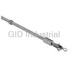
EATON BUSSMANN BDFHS22
Description
Switch Access Fusible Disconnect Switch Shaft
BDFHS22
Part Number
BDFHS22
Price
Request Quote
Manufacturer
EATON BUSSMANN
Lead Time
Request Quote
Category
Sensors and Transducers » Switch Accessories
Specifications
Manufacturer
Eaton Bussmann
Manufacturers Part #
BDFHS22
Industry Aliases
BDFHS22
Sub-Categories
Switch Accessories
Factory Pack Quantity
1
Datasheet

Extracted Text
Disconnect Switches Productivity Through Protection™ Table of Contents Disconnect Switches Compact, Heavy-Duty Table of Contents Fusible Disconnect Switches .....................................Page 2 Non-Fusible Disconnect Switches ...........................Page 29 Enclosed Fusible Disconnect Switches ..................Page 71 Enclosed Non-Fusible Disconnect Switches ..........Page 75 Index by Part Number ............................................... Page 86 NewDiscCatalogFinal4a.indd 1 3/29/2010 12:34:57 PM Enclosed Non-Fused Enclosed Fused Non-Fused Enclosed Non-Fused Enclosed Fused Non-Fused Fusible Fusible Non-Fused Enclosed Fused Enclosed Non-Fused Overview for Fusible Disconnect Switches CFD30CC3 – FD800L3 CFD30AJ3 CFD60J3 CFD100J3 FD400J3 FD600J3 FD800L3 Catalog number 3 pole CFD30ACC3 CFD30AJ3 CFD60J3 CFD100J3 CFD200J03 FD400J3 FD600J3 FD800L3 General purpose amp rating A 30 30 60 100 200 400 600 800 1 Approvals 2 pole N/A N/A N/A UL98 & IEC UL98 & IEC UL98 & IEC UL98 & IEC UL98 & IEC 3 pole UL98 & IEC UL98 & IEC UL98 & IEC UL98 & IEC UL98 & IEC UL98 & IEC UL98 & IEC UL98 & IEC 4 pole UL98 & IEC UL98 & IEC UL98 & IEC UL98 & IEC UL98 & IEC UL98 & IEC UL98 & IEC UL98 & IEC Technical ratings (UL, cULus) Max operating voltage V 600 600 600 600 600 600 600 600 Max horsepower rating Three phase 200 – 208V HP 5/7.5 5/7.5 15 25 50 100/125 150 200 240V HP 7.5 7.5 15 30 60 125 200 250 480V HP 15 15 30 60 125 250 400 500 600V HP 20 20 50 75 150 350 500 600 Single phase 120V HP 2 2 — — — — — — 240V HP 3 3 — — — — — — UL fuse class CC J J J J J,T J,T L Technical ratings (IEC) Rated insulation and operational 2 voltage. AC20 and DC20 1000 1000 750 750 1000 1000 1000 1000 Rated thermal current, I th AC 20/DC 20 open A 32 32 63 125 200 400 630 800 AC 20/DC 20 enclosed A 32 32 63 125 200 400 600 720 AC 21A 500V A 32 32 63 125 200 400 630 800 690V A 32 32 63 125 200 400 630 800 Rated operational power AC23 400/415V kW 14/15 14/15 30 80/90 110 210/230 315/340 350/380 690V kW 25 25 60 132 200 330 540 600 Physical characteristics Weight 3 pole switch lb 1.54 1.54 2.86 3.30 5.9 17.2 37.48 37.48 4 pole lb 1.98 1.98 3.52 3.96 7.5 19.4 46.3 46.3 Dimension 3 pole H in 3.82 3.82 3.94 5.66 6.5 7.87 11.42 11.42 W in 4.17 4.17 5.63 7.06 7.1 11.22 14.69 14.69 D in 4.21 4.21 5.04 5.09 5.2 8.11 9.21 9.21 Accessories Double break contacts S S S S S S S S Fuse cover S S S S S S S Terminal lug kit Integral Integral Integral BDTL24 CDTL200 BDTL26 BDTL27 BDTL27 Terminal shroud Not required Not required Not required Auxiliary contact Handle UL/NEMA type Type 1, 3R, 12 Type 1, 3R, 4, 4X, 12 Conversion kit 6 pole Electrical interlock — — — — S = Standard UL Listed, cULus approved, IEC rated, CE marked = Available — = Not available 1 UL Listed switches are also cULus approved. 2 1000V IEC 408 2 NewDiscCatalogFinal4a.indd 2 3/29/2010 12:35:08 PM 30A Fusible Disconnect Switches Base & DIN Rail Mounted UL Fuse Class J, CC For a complete assembly, please select one of each: 1 switch 1 handle 1 shaft CFD30AJ3 + BDS__ + CDH3S 30 Amp switches, 600V Maximum horsepower rating Terminal lugs UL UL general Fuse Three phase purpose type Wire Wire Catalog amp rating 600V 200V 208V 240V 480V 600V size type number 3 pole 30 J 5 7.5 7.5 15 20 #18 – 8 Cu CFD30AJ3 301 CC 5 7.5 7.5 15 20 #18 – 8 Cu CFD30ACC3 4 pole 30 J 5 7.5 7.5 15 20 #18 – 8 Cu CFD30AJ4 CFD30AJ3 301 CC 5 7.5 7.5 15 20 #18 – 8 Cu CFD30ACC4 Selector handles — for use with shafts .24 x .24" ( 6 x 6 mm) NEMA IEC Weight Catalog Color Defeatable Padlockable type type (lbs.) number CBDH3S, 5S All marked both O/I & Off/On 1,3R,12 IP65 Black — Yes 0.16 CBDH3S 1,3R,12 IP65 Red/Yellow — Yes 0.16 CBDH4S 1,3R,12 IP65 Black Yes Yes 0.16 CBDH5S 1,3R,12 IP65 Red/Yellow Yes Yes 0.16 CBDH6S CBDH4S, 6S Shafts — for use with CBDH selector handles .24 x .24" ( 6 x 6 mm) Shaft length Mounting depth Weight Catalog (inches/mm) (in inches) (lbs.) number 3.3/85 5.5 – 5.7 0.04 BDS85S 4.1/105 5.5 – 6.5 0.04 BDS105S 4.7/120 5.5 – 7.1 0.05 BDS120S 5.1/130 5.5 – 7.5 0.05 BDS130S 7.1/180 6.3 – 9.4 0.08 BDS180S 9.8/250 9.1 – 12.2 0.10 BDS250S 13.0/330 12.2 – 15.4 0.14 BDS330S BDS__ 1 Rejection style fuses only. 3 NewDiscCatalogFinal4a.indd 3 3/29/2010 12:35:09 PM Enclosed Non-Fused Enclosed Fused Non-Fused Fusible Fusible Non-Fused Enclosed Fused Enclosed Non-Fused Handles & Shafts for 30A Fusible Disconnect Switches For a complete assembly, please select one of each: 1 switch 1 handle 1 shaft CFD30AJ3 + BDS__ + BDH59 Pistol handles — for use with shafts .24 x .24" ( 6 x 6 mm) NEMA IEC Length Weight Catalog Color Marking Defeatable Padlockable type type inches/mm (lbs.) number 1,3R,12 IP65 Black O/I & Off/On 1.8/45 Yes Yes 0.28 BDH56 1,3R,12 IP65 Red/Yellow O/I & Off/On 1.8/45 Yes Yes 0.28 BDH57 1,3R,12 IP65 Black O/I & Off/On 2.6/65 Yes Yes 0.29 BDH58 1,3R,12 IP65 Red/Yellow O/I & Off/On 2.6/65 Yes Yes 0.29 BDH59 BDH56, BDH58 1,3R,4,4X,12 IP65 Black O/I & Off/On 2.6/65 Yes Yes 0.29 CDHXB65L6 1,3R,4,4X,12 IP65 Red/Yellow O/I & Off/On 2.6/65 Yes Yes 0.29 CDHXY65L6 1,3R,12 IP65 Black Off/On/Test 2.6/65 Yes Yes 0.29 BDH58T 1,3R,12 IP65 Red/Yellow Off/On/Test 2.6/65 Yes Yes 0.29 BDH59T BDH57, BDH59 Shafts — for use with pistol handles .24 x .24" ( 6 x 6 mm) Shaft length Mounting depth Weight Catalog (inches/mm) (in inches) (lbs.) number 5.9/150 4.9 – 8.9 0.07 BDS150 6.7/170 5.9 – 9.7 0.08 BDS170 10.4/265 9.5 – 13.4 0.12 BDS265 15.8/400 15.0 – 18.7 0.18 BDS400 BDS__ 19.7/500 20.5 – 22.6 0.23 BDS500 Direct mount handle — mounts directly to switch, no shaft necessary NEMA Length Weight Catalog Color Marking Padlockable type mm (lbs.) number 1 Blk O/I/Test 50 Yes 0.10 BDHA79 BDHA79 5.20" 132mm 5.20"/132mm BDHA79 Mounted BDHA79 Mounted depth 4 NewDiscCatalogFinal4a.indd 4 3/29/2010 12:35:09 PM Accessories for 30A Fusible Disconnect Switches 1 Auxiliary contacts Weight AC thermal AC rated Catalog Description For use on: (lbs) amp rating voltage number Form C 1 N.O. & 1 N.C. CFD30_ for direct mounting 0.04 6 250 BDAUX157 (2 maximum) to switch 1 N.O. CFD30_ CDAUX10 1 N.C. CDAUXB mounting 0.03 NEMA A600,P600 CDAUX01K (6 maximum) base required CFD30AJ3 with auxiliaries Mounting base Weight Catalog Description For use with: (lbs) number Mounting base CDAUX10, CDAUX01K 0.08 CDAUXB Terminal pole Weight AC thermal AC rated Catalog Description For use on: (lbs) amp rating voltage number Detachable neutral mounts CFD30_ 0.45 30 600 CFDZX171 CFDZX171 on side of switch or DIN rail DIN rail Weight Length Catalog Description For use on: (lbs.) inches/mm number 35mm DIN Rail CFD30_ .38 39.4/1000 NDNA100 35mm Aluminum DIN Rail CFD30_ .75 78.8/2000 NDNA200 NDNA100 Fuse Carriers (Replacement Parts) Catalog Description For use on: number CC fuse carrier BDCF30CC_ BDZD48 J fuse carrier BDCF30J_ BDZD28 Class CC Solid link CFD30_ NNB-R BDZD48 Terminal cover (replacement part) Catalog Description For use on: number Covers terminal CFD30_ CDBY67121 below fuse carrier CXBY67121 1 UL File # E83510 5 NewDiscCatalogFinal4a.indd 5 3/29/2010 12:35:09 PM Enclosed Non-Fused Enclosed Fused Non-Fused Fusible Fusible Non-Fused Enclosed Fused Enclosed Non-Fused Accessories for 30A Fusible Disconnect Switches Conversion mechanisms Switches are not included Weight Catalog Description For use on: (lbs) number 6 pole CFD30 1.74 BDZW6 8 pole CFD30 1.90 BDZXB8 BDZW6 6 or 8 pole — BDZW5 6 (8) pole mechanism allows two switches, controlled by one handle, to open or close 1 POS. O POS. I simultaneously. Equipment required for a complete installation: SW. A O X One conversion mechanism SW. B O X Two disconnect switches One handle X = Closed O = Open One 5 mm shaft 1 = Three poles 6 NewDiscCatalogFinal4a.indd 6 3/29/2010 12:35:10 PM 60A – 100A for Fusible Disconnect Switches UL Fuse Class J For a complete assembly, please select one of each: 1 switch 1 handle 1 shaft 1 terminal lug kit CFD60J3 + BDS210 + BDH58 60 – 100 Amp switches, 600V UL UL Maximum horsepower rating general Fuse Three phase purpose type Catalog amp rating 600V 200V 208V 240V 480V 600V number 3 pole 3 pole 60 J 15 15 15 30 50 CFD60J3 100 J 25 25 30 60 75 CFD100J3 CFD60J3 4 pole 4 pole 60 J 15 15 15 30 50 CFD60J4 100 J 25 25 30 60 75 CFD100J4 Pistol handles — .24 x .24" ( 6 x 6mm) NEMA/UL IEC Color Length Marking Defeatable Padlockable Weight Catalog type type in/mm (lbs.) number 1,3R,12 IP65 Black 2.6/65 O/I & Off/On Yes Yes 0.29 BDH58 1,3R,12 IP65 Red/Yel 2.6/65 O/I & Off/On Yes Yes 0.29 BDH59 CFD100J3 1,3R,12 IP65 Black 3.1/80 O/I & Off/On Yes Yes 0.30 BDH60 1,3R,12 IP65 Red/Yel 3.1/80 O/I & Off/On Yes Yes 0.30 BDH61 1,3R,4,4X,12 IP65 Black 3.1/80 O/I & Off/On Yes Yes 0.30 CDHXB86 1,3R,4,4X,12 IP65 Red/Yel 3.1/80 O/I & Off/On Yes Yes 0.30 CDHXY86 Shafts — .24 x .24" ( 6 x 6mm) BDH58,60 Shaft length Mounting depth Weight Catalog (inches/mm) (inches) (lbs.) number 5.9/150 5.5 – 8.5 0.09 BDS150 8.3/210 8.0 – 11.0 0.13 BDS210 11.4/290 11.0 – 14.0 0.18 BDS290 14.2/360 13.8 – 16.8 0.23 BDS360 16.9/430 16.5 – 19.7 0.27 BDS430 BDH59,61 Twisted shafts — Rotates handle 45° .24 x .24" ( 6 x 6mm) Shaft length Mounting depth Weight Catalog (inches/mm) (inches) (lbs.) number 5.1/130 4.8 – 7.8 0.08 BDST4 8.3/210 8.0 – 11.0 0.13 BDST25 11.4/290 11.0 – 14.0 0.18 BDST29 14.2/360 13.8 – 16.8 0.23 BDST30 BDS__ Direct mount handle — mounts directly to switch, no shaft necessary NEMA Color Marking Length Padlockable Weight Catalog type mm (lbs.) number 1 Black O/I/Test 50 Yes 0.10 CDH4 BDST_ 7 NewDiscCatalogFinal4a.indd 7 3/29/2010 12:35:10 PM Enclosed Non-Fused Enclosed Fused Non-Fused Fusible Fusible Non-Fused Enclosed Fused Enclosed Non-Fused Accessories for 60A – 100A Fusible Disconnect Switches Terminal lug kit Kit For use on: Wire size weight Wire Terminal Catalog (lbs) type lugs per kit number CFD60J_ #14 – 4 — Cu — Integral CFD100J_ #14 – 2/0 0.43 Cu/Al 6 BDTL24 BDTL24 Auxiliary contacts Description For use on: Weight AC thermal AC rated Catalog (lbs) amp rating voltage number 1 N.O. 0.07 10 600 CDAUX10 1 N.C. CFD60 – CFD100 0.07 10 600 CDAUX01K CDAUX10, CDAUX01K Replacement fuse clip Catalog Description For use on: number Removable fuse carrier CFD60 CFC60J CFC60J CFCVR100 Replacement fuse covers Catalog Description For use on: number Transparent fuse cover CFD100 CFCVR100 Terminal shroud Description For use on: Weight Catalog CFTS100 (lbs) number Includes one terminal shroud CFD100, 1-POLE 0.04 CFTS100 for line or load side Terminal poles Weight AC thermal AC rated Catalog Description For use on: (lbs) amp rating voltage number Detachable neutral CFD60 0.13 63 600 CFZ1 CFZ1 mounts on side of switch or DIN rail CFD100 0.31 125 600 CFZ2 DIN rail Weight Length Catalog Description For use on: NDNA100 (lbs.) inches/mm number 35mm Aluminum DIN Rail CFD60 .38 39.4/1000 NDNA100 35mm Aluminum DIN Rail CFD60 .75 78.8/1000 NDNA200 “T” type fuse adapter kit Catalog Description For use on: number 100A, 600V CFD100 BDTA1 BDTA1 8 NewDiscCatalogFinal4a.indd 8 3/29/2010 12:35:10 PM Accessories for 60A – 100A Fusible Disconnect Switches Locking accessories Description For use on: Weight Catalog (lbs) number Cam attachment for Kirk Key, Castell, Lowe & Fletcher and Ronis interlock. Cam attachment CFD60 – 0.25 CDETL-ZW16 for adapting to the interlock system. CFD100 The interlock is not included. CDETL-ZW16 Shaft extension coupler Weight Catalog Description For use on: (lbs) number Joins two shafts together for applications where 6mm shafts 0.26 BDZX167 BDZX167 extended length is required 12mm shafts 0.26 BDZW95 BDZW95 Shaft adapter Weight Catalog Description For use on: (lbs) number Adapts one end of a 6mm shaft to 12mm. Use with 6mm shafts 0.20 CDZK19 shaft extension coupler CDZK19 (X=6MM) Conversion mechanisms Switches are not included Weight Catalog Description For use on: (lbs) number 6 and 8 pole CFD60 – CFD100 1.52 BDZW2 Mechanical interlock CFD60 – CFD100 0.55 BDZW10 6 or 8 pole — BDZW2 BDZW2 1 6 (8) pole mechanism allows two switches controlled by one handle, to open or close simultaneously. POS. O POS. I Shafts included. SW. A O X Equipment required for a complete installation: SW. B O X One conversion mechanism Two disconnect switches X = Closed One handle O = Open 1 = Three poles 9 NewDiscCatalogFinal4a.indd 9 3/29/2010 12:35:11 PM x-1 x 12 Enclosed Non-Fused Enclosed Fused Non-Fused Fusible Fusible Non-Fused Enclosed Fused Enclosed Non-Fused 200A Fusible Disconnect Switches UL Fuse Class J For a complete assembly, please select one of each: 1 switch 1 handle 1 shaft CFD200J03 + BDS210 + BDH58 + CDTL200 1 terminal lug kit 200 Amp Switches, 600V UL UL Maximum horsepower rating general fuse Three phase Catalog purpose type amp rating 600V 200V 208V 240V 480V 600V number 3 pole 200 J 50 50 60 125 150 CFD200J03 BDH58,60 4 pole 200 J 50 50 60 125 150 CFD200J04 Pistol handles - .24 x .24” ( 6 x 6mm) Length Catalog NEMA type IEC type Color Marking Defeatable Padlockable Weight UL/ inches/mm number (lbs) 1,3R,12 IP65 Black 2.6/65 O/I & Off/On Yes Yes 0.29 BDH58 1,3R,12 IP65 Red/Yel 2.6/65 O/I & Off/On Yes Yes 0.29 BDH59 1,3R,12 IP65 Black 3.1/80 O/I & Off/On Yes Yes 0.30 BDH60 BDH58,61 1,3R,12 IP65 Red/Yel 3.1/80 O/I & Off/On Yes Yes 0.30 BDH61 1,3R,4,4X,1 IP65 Black 3.1/80 O/I & Off/On Yes Yes 0.30 CDHXB86 1,3R,4,4X,12 IP65 Red/Yel 3.1/80 O/I & Off/On Yes Yes 0.30 CDHXY86 Shafts - .24 x .24” ( 6 x 6mm) Shaft length Mounting dept Weight (inches/mm) (inches) (lbs) Catalog number 5.9/150 5.5-8.5 0.09 BDS150 BDS_ 8.3/210 8.0-11.0 0.13 BDS210 11.4/290 11.0-14.0 0.18 BDS290 14.2/360 13.8-16.8 0.23 BDS360 16.9/430 16.5-19.7 0.27 BDS430 Twisted shafts - rotates handle 45˚ � .24 x .24” (� 6 x 6mm) Shaft length Mounting dept Weight (inches/mm) (inches) (lbs) Catalog number 5.1/130 4.8-7.8 0.08 BDST4 BDST_ 8.3/210 8.0-11.0 0.13 BDST25 11.4/290 11.0-14.0 0.18 BDST29 14.2/360 13.8-16.8 0.23 BDST30 Direct mount handle - mounts directly to switch, no shaft necessary Nema Type Color Marking Padlockable (lbs) Catalog number 1 Black O/I Yes 0.1 CDHSB20 1 Red/Yel O/I Yes 0.3 CDHSY20 10 NewDiscCatalogFinal4a.indd 10 3/29/2010 12:35:11 PM Accessories for 200A Fusible Disconnect Switches Terminal Lug Kits Wire Wire Terminal Weight For use on: Size Type Description lugs per kit (lbs) Catalog number #4-300kcmil --- 6 0.5 CDTL200 CFD200JO3 #4-300kcmil --- 3 0.25 CDTL200/3P CFD200J04 (6) 14-6 AWG Cu/Al Distribution 3 CDTL206 lug CDTL200 Auxiliary Contacts Weight Description For use on: (lbs) Catalog number 1 N.O. 0.07 CDAUX10 CFD200J03, CFD200J04 1 N.C. 0.07 CDAUX01K Module for auxililary contacts CDAUX10, CDAUX01K Weight Description (lbs) Catalog number Screw mounting to the left side of the switch 0.1 CDAUXM28 Mounting on the left side of the switch: Max. 8 auxiliary contact blocks with the CDAUXM28 Mounting under the mechanism cover: Max. 4 auxiliary contact blocks Replacement parts Description For use on: Catalog number CDSS200S3 Fuse cover CFD200J03 and CFCVR200 Phase barrier CFD200J04 CPBR200 Terminal Number Weight For use on: Description of poles (lbs) Catalog number Long type 3 0.2 CDSS200L3 Short type 3 0.13 CDSS200S3 CFD200J03 and CFD200J04 Long type 4 0.26 CDSS200L4 Short type 4 0.18 CDSS200S4 CDSS200L3 Terminal poles Weight AC thermal AC rated Description (lbs) amp rating voltage Catalog number Detachable neutral mounts on side of 0.88 200 600 CDD200P switch or DIN CDETL-ZW16 Locking accessories Weight Description (lbs) Catalog number Cam attachment for Kirk Key, Castell, Lowe & Fletcher and Ronis interlock. Cam attachment for adapting to the interlock system. The interlock is not included. 0.25 CDETL-ZW16 11 NewDiscCatalogFinal4a.indd 11 3/29/2010 12:35:11 PM Enclosed Non-Fused Enclosed Fused Non-Fused Fusible Fusible Non-Fused Enclosed Fused Enclosed Non-Fused Accessories for 200A Fusible Disconnect Switches Shaft extension coupler Weight Description For use on: (lbs) Catalog number Joins two shafts together for applications 6mm shafts BDZX167 0.26 where extended length is required 12mm shafts BDZX95 BDZX167, BDZW95 Shaft adapter Description For use on: Catalog number Adapts one end of a 6mm shaft to 12mm. 6mm shafts CDZK19 Use with shaft extension coupler. CDZK19 (X=6mm) Conversion mechanisms Weight Description (lbs) UL/NEMA type Catalog number 6 and 8 pole 1.52 ----------------------- BDZW2 BDZW2 12 NewDiscCatalogFinal4a.indd 12 3/29/2010 12:35:12 PM x-1 x 12 400A – 800A Fusible Disconnect Switches UL Fuse Class J, T, L For a complete assembly, please select one of each: 1 switch 1 handle 1 shaft 1 terminal lug kit FD400J3 + BDS280 + BDH114 + BDTL26 400 – 800 Amp switches, 600V Maximum horsepower rating UL UL general Fuse Three phase purpose type Catalog amp rating 600V 200V 208V 240V 480V 600V number 2 pole 2 pole 1 400 J — — — — — FD400J2 1 600 J — — — — — FD600J2 800 L — — — — — FD800L2 3 pole 3 pole 1 400 J 100 125 125 250 350 FD400J3 FD400J3 1 600 J 150 150 200 400 500 FD600J3 800 L 200 200 250 500 600 FD800L3 4 pole 4 pole 1 400 J 100 125 125 250 350 FD400J4 60A - 100A 1 600 J 150 150 200 400 500 FD600J4 800 L 200 200 250 500 600 FD800L4 UL Fuse Class J Pistol handles — .47 x .47" ( 12 x 12mm) FD600J3 NEMA IEC Color Length Marking Defeatable Padlockable Weight Catalog FD800L3 type type inches/mm (lbs) number 1,3R,12 IP65 Black 4.9/125 O/I & Off/On Yes Yes 0.39 BDH112 1,3R,12 IP65 Red/Yel 4.9/125 O/I & Off/On Yes Yes 0.39 BDH113 1,3R,12 IP65 Black 5.7/145 O/I & Off/On Yes Yes 0.39 BDH114 1,3R,12 IP65 Red/Yel 5.7/145 O/I & Off/On Yes Yes 0.39 BDH115 1,3R,12 IP65 Black 6.9/175 O/I & Off/On Yes Yes 0.41 BDH116 1,3R,12 IP65 Red/Yel 6.9/175 O/I & Off/On Yes Yes 0.41 BDH117 1,3R,4,4X,12 IP65 Black 5.7/145 O/I & Off/On Yes Yes 0.39 CDHXB12 1,3R,4,4X,12 IP65 Red/Yel 5.7/145 O/I & Off/On Yes Yes 0.39 CDHXY12 BDH112 1,3R,4,4X,12 IP65 Black 6.9/175 O/I & Off/On Yes Yes 0.41 CDHXB22 1,3R,4,4X,12 IP65 Red/Yel 6.9/175 O/I & Off/On Yes Yes 0.41 CDHXY22 1,3R,4,4X,12 IP65 Metal 8.7/220 Off/On — Yes 1.50 BDH8 BDH113 1 J type fuse clips are standard. If 600V Type “T” fuse clips are desired, please order a "T" type fuse adapter kit. 13 NewDiscCatalogFinal4a.indd 13 3/29/2010 12:35:12 PM Enclosed Non-Fused Enclosed Fused Non-Fused Fusible Fusible Non-Fused Enclosed Fused Enclosed Non-Fused Accessories for 400A – 800A Fusible Disconnect Switches Shafts — .47 x .47" ( 12 x 12mm) 1 Shaft length Mounting depth in inches Weight Catalog For use on FD400J_ 8.7/220 7.9 – 12.2 0.61 BDS220 9.8/250 9.1 – 13.4 0.70 BDS250 BDS__ 11.0/280 10.2 – 14.5 0.77 BDS280 12.8/325 12.0 – 16.3 0.90 BDS325 15.6/395 14.8 – 19.1 1.10 BDS395 18.3/465 17.5 – 21.9 1.32 BDS465 21.1/535 20.3 – 24.6 1.54 BDS535 For use on FD600J_ – FD800J_ 9.8/250 10.0 – 12.8 0.70 BDS250 11.0/280 11.2 – 14.0 0.77 BDS280 12.8/325 13.0 – 15.8 0.90 BDS325 BDS_45 15.6/395 15.8 – 18.6 1.10 BDS395 18.3/465 18.5 – 21.3 1.32 BDS465 21.1/535 21.1 – 24.1 1.54 BDS535 Twisted shafts — Rotates handle 45° .47 x .47" ( 12 x 12mm) BDTL26 Shaft length Mounting depth Weight Catalog (inches/mm) (inches) (lbs.) number For use on FD400J_ 11.0/280 10.2 – 14.5 0.77 BDS28045 12.8/325 12.0 – 16.3 0.90 BDS32545 18.3/465 17.5 – 21.9 1.32 BDS46545 For use on FD600J_ – FD800J_ BDTL27 11.0/280 11.2 – 14.0 0.77 BDS28045 12.8/325 13.0 – 15.8 0.90 BDS32545 18.3/465 18.5 – 21.3 1.32 BDS46545 Terminal lug kit Kit For use on: Wire weight Wire Terminal Catalog size (lbs) type lugs per kit number FD400J_ #2 – 600 kcmil 3.50 Cu/Al 6 BDTL26 FD600J – FD800L (12)#14-16 – 600 kcmil 1.10 Cu/Al 3 BDTL175/400 FD600J_ & FD800L_ (2)#2 – 600 kcmil 4.62 Cu/Al 6 BDTL27 BDTL175/400 “T” type fuse adapter kit For use on: AC thermal AC rated Poles Catalog amp rating voltage number FD400J_ 400 600 3 BDTA4 FD600J_ 600 600 3 BDTA6 BDTA_ 1 Mounting depth is the distance from the outside of the door to the disconnect switch mounting plate. Shaft can be cut to desired length. 14 NewDiscCatalogFinal4a.indd 14 3/29/2010 12:35:12 PM Accessories for 400A – 800A Fusible Disconnect Switches 1 Auxiliary contacts Description For use on: Weight AC thermal AC rated Catalog (lbs) amp rating voltage number 1 N.O. + 1 N.C. 0.20 10 600 BDAUX1 2 N.O. + 2 N.C. 0.26 10 600 BDAUX2 4 N.O. + 4 N.C. FD400 – 0.40 10 600 BDAUX3 2 N.O. FD800 0.18 10 600 BDAUX4 4 N.O. 0.25 10 600 BDAUX5 8 N.O. 0.40 10 600 BDAUX6 BDAUX_ 200A & 400A 600A & 800A Switches Switches Fuse covers (replacement part) Description For use on: Weight Catalog (lbs) number 2 pole 0.30 BDZX271 3 pole FD400 0.40 BDZX272 4 pole 0.53 BDZX273 2 pole 0.40 BDZX216 3 pole FD600 – 0.50 BDZX196 4 pole FD800 0.67 BDZX197 BDZX271 BDZX272 BDZX216 BDZX196 BDZX273 BDZX197 Fuse cover interlock Catalog Description For use on: number Prevents the fuse cover from being opened when the switch FD400- BDZX204 is in the ON position FD800 BDZX204 Terminal shroud Description For use on: Weight Catalog (lbs) number Includes one terminal shroud for FD400 0.13 BDTSF4 line or load side FD600 – FD800 0.11 BDTSF6 BDT5F_ Terminal pole Description For use on: Weight AC thermal AC rated Catalog (lbs) amp rating voltage number 1.04 400 600 BDTP85 Detachable neutral mounts on FD400 side of switch or DIN rail FD600 – 1.19 800 600 BDTP88 FD800 BDTP85 BDTP88 1 UL fi le #E57057 15 NewDiscCatalogFinal4a.indd 15 3/29/2010 12:35:13 PM Enclosed Non-Fused Enclosed Fused Non-Fused Fusible Fusible Non-Fused Enclosed Fused Enclosed Non-Fused Accessories for 400A – 800A Fusible Disconnect Switches Locking accessories Weight Catalog Description For use on: (lbs) number Cam attachment for Kirk Key, Castell, Lowe & Fletcher and FD400 – Ronis interlock. For adapting 0.29 CDETL-ZW5 to the interlock system. FD800 The interlock is not included. Electrical interlock Closed circuit principle for interlocking the switch movement. When the coil circuit is dead, A-types cannot FD600 – be operated to ON-position and 2.42 CDETL-ZT80A/� L-types cannot be operated to FD800 ON- or OFF-position. CDETL-ZT80L/� CDETL-ZW5 Coil voltages 110VAC, 220VAC, 24VDC, 48VDC, 60 VDC 110VDC, 220VDC, P = 15W H - Coil voltage Shaft extension coupler Weight Catalog Description For use on: (lbs) number CDETL-ZT80 Joins two shafts together for applications where 12mm shafts 0.26 BDZW95 extended length is required BDZW95 Shorting bars AC thermal AC rated Catalog Description For use on: amp rating voltage number 400 600 FDSBZK98 Solid links FD400 (1 per kit) FD600 – 800 600 FDSBZL79 FD800 FDSBZK98 FDSBZL79 90° angle kit Description For use on: Weight Catalog (lbs) number Converts switch mechanism from FD400 – 4.63 BDZX108 front operation to side operation FD800 BDZX108 16 NewDiscCatalogFinal4a.indd 16 3/29/2010 12:35:13 PM Accessories for 400A – 800A Fusible Disconnect Switches Conversion mechanisms Switches are not included Description For use on: Weight Catalog (lbs) number 6 or 8 pole 2.42 BDZW9 FD400 – FD800 BDZW9 6 or 8 pole — BDZW9 6 (8) pole mechanism allows two switches 1 controlled by one handle, to open or close POS. O POS. I simultaneously. SW. A O X Equipment required for a complete installation: SW. B O X One conversion mechanism X = Closed Two disconnect switches O = Open One handle One additional shaft (Only one shaft is included with mechanism) 1 = Three poles 17 NewDiscCatalogFinal4a.indd 17 3/29/2010 12:35:13 PM Enclosed Non-Fused Enclosed Fused Non-Fused Fusible Fusible Non-Fused Enclosed Fused Enclosed Non-Fused Side Operated Fusible Disconnect Switches for 30A – 400A UL Fuse Class J, CC, T For a complete assembly, please select one of each: 1 switch 1 handle 1 shaft CFD30AJ3S + BDS170 + BDH59SH 1 terminal lug kit Side operated switches — 3 pole UL UL Maximum horsepower rating general fuse Three phase purpose type Weight Catalog amp rating 600V 200V 208V 240V 480V 600V (lbs) number 30 J 5 7.5 7.5 15 20 1.54 CFD30AJ3S 30 CC 5 7.5 7.5 15 20 1.54 CFD30ACC3S 60 J 15 15 15 30 50 3.52 CFD60J3S 1 100 J 25 25 30 60 75 3.97 CFD100J3S 1 200 J 50 50 60 125 150 15.21 FD200J3-S 1 400 J 100 125 125 250 350 17.20 FD400J3-S CFD60J3S Handles Length Catalog NEMA type IEC type Color Marking Defeatable Padlockable Weight inches/mm number For use with CFD30J3S & CFD30CC3S 1, 3R, 12 IP65 Black 2.6/65 OFF/ON/TEST Yes Yes 0.29 BDH58SH 1, 3R, 12 IP65 Red/Yellow 2.6/65 OFF/ON/TEST Yes Yes 0.29 BDH59SH For use with CFD60J3S & CFD100J3S 1, 3R, 12 IP65 Black 3.1/80 OFF/ON/TEST Yes Yes 0.30 BDH110SH CFD100J3S 1, 3R, 12 IP65 Red/Yellow 3.1/80 OFF/ON/TEST Yes Yes 0.30 BDH111SH For use with FD200J3-S & FD400J3-S 1, 3R, 12 IP65 Black 4.9/145 OFF/ON/TEST Yes Yes 0.39 BDH114SH 1, 3R, 12 IP65 Red/Yellow 4.9/145 OFF/ON/TEST Yes Yes 0.39 BDH115SH 1, 3R, 12 IP65 Metal 4.9/145 OFF/ON/TEST — Yes 1.50 BDZX74 — = No Shafts Length Weight Catalog For use with: Description (inches/mm) (lbs.) number CFD30AJ3S & CFD30ACC3S 6.7/170 0.24 x 0.24" (6 x 6mm) 0.08 BDS170 CFD60J3S & CFD100J3S 8.3/210 0.24 x 0.24" (6 x 6mm) 0.13 BDS210 FD200J3-S & FD400J3-S 12.8/325 0.47 x 0.47" (12 x 12mm) 0.90 BDS325 BDZX74 Terminal lug kit Wire Kit weight Wire Lugs Catalog For use on: size (lbs) type per kit number CFD30J3S & CFD30CC3S #14 – 4 — Cu — Integral CFD60J3S #14 – 4 — Cu — Integral CFD100J3S #14 – 2/0 0.43 Cu/Al 6 BDTL24 FD200J3-S #6 – 300 kcmil 0.93 Cu/AI 6 BDTL25 BDS325 FD400J3-S #2 – 600 kcmil 3.50 Cu/AI 6 BDTL26 BDTL25 1 J type fuse clips are standard. If 600V Type "T" fuse clips are desired, please order the "T" type fuse adapter kit. 18 NewDiscCatalogFinal4a.indd 18 3/29/2010 12:35:13 PM Flange Operated Fusible Disconnect Switches for 30A – 100A UL Fuse Class J, CC, T For a complete assembly, please select one of each: 1 switch 1 handle 1 shaft CFD30J3F + BDFHS12 + BDFHNHS12 1 terminal lug kit Flange operated switches — 3 pole UL UL Maximum horsepower rating general fuse Three phase purpose type Weight Catalog amp rating 600V 200V 208V 240V 480V 600V (lbs) number 30 J 5 7.5 7.5 15 20 2.20 CFD30AJ3F 30 CC 5 7.5 7.5 15 20 2.50 CFD30ACC3F 60 J 15 15 15 30 50 3.52 CFD60J3F 100 J 25 25 30 60 75 3.97 CFD100J3F Handles NEMA Length Weight Catalog Color Marking Defeatable Padlockable type inches/mm (lbs) number 1, 3R, 12 Metal 6.9/175 O/I & OFF/ON Yes Yes 3.52 BDFHNHS12 4, 4X Metal 6.9/175 O/I & OFF/ON Yes Yes 3.52 BDFHNHS4 BDFHNHS__ Shafts Shaft length Mounting depth Weight Catalog inches in inches (lbs) number 12 0.39 BDFHS12 17 0.55 BDFHS17 22.5 0.73 BDFHS22 Terminal lug kit BDFHS__ Wire Kit weight Wire Lugs Catalog For use on: size (lbs) type per kit number BDCF30J6_& #14 – #4 — Cu — Standard BDFLF60J6-F #14 – #4 — Cu — Standard BDFLF100J6-F #14 – 2/0 0.43 Cu/Al 6 BDTL24 Door hardware — NEMA 12 Weight Catalog Item (lbs) number BDTL24 Safety door latch, 1.92 BDDHK 2 point with 6" handle Roller for 3 point latch, 0.39 BD3RL add to FH-DHK 19 NewDiscCatalogFinal4a.indd 19 3/29/2010 12:35:14 PM Enclosed Non-Fused Enclosed Fused Non-Fused Fusible Fusible Non-Fused Enclosed Fused Enclosed Non-Fused Cable Operated Fusible Disconnect Switches for 30A – 800A UL Fuse Class CC, J, L & T For a complete assembly, please select one each of the following: + + ++ Handle Switch Cable Lug kit (as required) Operating mechanism Fusible UL UL Maximum horsepower rating general fuse Three-phase purpose type Mechanism Switch amp rating 600V 200-208V 240V 480V 600V Poles Part Number Part Number 30 CC 5/7.5 7.5 15 20 3 BMKCS2 CFD30ACC3 30 J 5/7.5 7.5 15 20 3 BMKCS2 CFD30AJ3 60 J 15 15 30 50 3 BMKCS3 CFD60J3 100 J/T 25 30 60 75 3 BMKCS4 CFD100AJ3 200 J 50 60 125 150 3 BMKCS4 CFD200J03 Switch 400 J/T 100 125 250 350 3 Incl. FD400J3-FC 600 J/T 150 200 400 500 3 Incl. FD600J3-FC 800 L 200 250 500 600 3 Incl. FD800J3-FC Flange handles - UL 98; File #E101914 Environmental Catalog For use with: rating number NEMA 1, 3R, 12 BDHFC12 CFD30 - CFD200 NEMA 4, 4X BDHFC4 Handle NEMA 1, 3R, 12 BK7FCH FD400 - FD-800 NEMA 4, 4X BK7FCH4 Flexible cables Cable length Catalog For use with: (inches) number 36 BFCL36 48 BFCL48 60 BFCL60 CFD30 - CFD200 72 BFCL72 84 BFCL84 96 BFCL96 108 BFCL108 BFCL36 - BFCL108 48 BK7C048 BK7C048 - BK7C084 60 BK7C060 FD400 - FD800 72 BK7C072 84 BK7C084 Terminal lug kits Wire Wire Lugs Catalog For use with: size type Description per kit number #4-300kcmil Cu/Al - 6 CDTL200 CFD100 - CFD200 #4-300kcmil Cu/Al - 3 CDTL200/3P Lug kit (6)#4-6AWG Cu/Al Dist. lug 3 CDTL206 FD400J #2-600kcmil Cu/Al 6 BDTL26 FD600J - FD800L (12)#14-16 - 600kcmil Cu/Al 3 BDTL175/400 FD600J - & FD800L (2)#2 - 600kcmil Cu/Al 6 BDTL27 Door hardware — NEMA 12 Catalog Item number Safety door latch, 2 point, door less than 40" high BKDH2R Safety door latch, 3 point, door greater than 40" high BKDH3R BDTL175/400 20 NewDiscCatalogFinal4a.indd 20 3/29/2010 12:35:14 PM UL & cULus Technical Data for Fusible Disconnect Switches CFD30CC3 – FD800L3 UL & cULus Catalog number 3 pole CFD30_3 CFD60J3 CFD100J3 CFD200J03 FD400J3 FD600J3 FD800L3 1 Approvals 2 pole N/A N/A UL98 & IEC UL98 & IEC UL98 & IEC UL98 & IEC UL98 & IEC 3 pole UL98 & IEC UL98 & IEC UL98 & IEC UL98 & IEC UL98 & IEC UL98 & IEC UL98 & IEC 4 pole UL98 & IEC UL98 & IEC UL98 & IEC UL98 & IEC UL98 & IEC UL98 & IEC UL98 & IEC Technical ratings -40° to 40°C General purpose amp rating A 30 60 100 200 400 600 800 pf = 0.7 – 0.8 Max operating voltage V 600 600 600 600 600 600 600 Max horsepower rating/ Max motor FLA current pf = 0.4 – 0.5 Three phase 200 – 208V HP/A 5/16.8 – 7.5/24.2 15/46.2 25/75.0 50/143.0 100/273 – 125/344 150/396 200/528 240V HP/A 7.5/22.0 15/42.0 30/80.0 60/145.0 125/312.0 200/480.0 250/602.0 480V HP/A 15/21.0 30/40.0 60/77.0 125/156.0 250/302.0 400/477.0 500/590.0 600V HP/A 20/22.0 50/52.0 75/77.0 150/144.0 350/336.0 500/472.0 600/ — Single phase 120V HP/A 2/24.0 — — — — — — 240V HP/A 3/17.0 — — — — — — Short circuit rating with fuse kA 200 200 200 200 200 200 200 UL Fuse size A 30 60 100 200 400 600 800 UL Fuse type J/CC J J/T J J/T J/T L Endurances Min. Electrical endurance, pf = 0.75 – 0.80 operation cycles 6000 6000 6000 6000 1000 1000 500 Mechanical endurance operation 20,000 20,000 20,000 20,000 12,000 10,000 7000 Physical characteristics Weight 3 pole lb 1.54 2.86 3.30 5.9 17.2 37.48 37.48 4 pole lb 1.98 3.52 3.96 7.5 19.4 46.3 46.3 Dimension 3 pole H in 3.82 3.94 5.66 6.5 7.87 11.42 11.42 W in 4.17 5.63 7.06 7.1 11.22 14.69 14.69 D in 4.21 5.04 5.09 5.2 8.11 9.21 9.21 Shaft size square in .24 x .24 .24 x .24 .24 x .24 .24 x .24 .47 x .47 .47 x .47 .47 x .47 mm 6 x 6 6 x 6 6 x 6 6 x 6 12 x 12 12 x 12 12 x 12 Switch operating torque lb. in. 26.6 35.5 70.9 195 195 248 248 for rotary 3 pole switches Terminal lug kits Integral Integral BDTL24 CDTL200 BDTL26 BDTL27 BDTL27 Wire range AWG #18 – 8 #14 – 4 #14 – 2/0 #4 – 300kcmil #2 – 600kcmil (2) #2 – 600 kcmil (2) #2 – 600 kcmil Torque: Wire tightening lb. in. 17 30 120 275 500 375 375 Lug mounting lb. in. N/A N/A 50 150 480 500 480 Auxiliary contacts NEMA ratings, AC — A600 A600 A600 A600 A600 A600 A600 AC rated voltage VAC 250 600 600 600 600 600 600 600 AC thermal rated current A 6 10 10 10 10 10 10 10 AC maximum volt ampere making VA 7200 7200 7200 7200 7200 7200 — 7200 AC maximum volt ampere breaking VA — 720 720 720 720 720 720 720 NEMA ratings, DC — P300 R300 R300 R300 P600 P600 P600 DC rated voltage VDC — 300 300 300 300 600 600 600 DC thermal rated current A — 1 1 1 1 5 5 5 DC maximum make break current A — 28 28 28 28 138 138 138 Torque: Wire tightening lb. in. 7 7 7 7 7 7 7 Wire range AWG #22 – 14/#18 – 14 #18 – 14 #22 – 14 #18 – 14 #22 – 14 #22 – 14 #22 – 14 1 The following UL Listed switches are also cULus approved. 21 NewDiscCatalogFinal4a.indd 21 3/29/2010 12:35:15 PM Enclosed Non-Fused Enclosed Fused Non-Fused Fusible Fusible Non-Fused Enclosed Fused Enclosed Non-Fused IEC Technical Data for Fusible Disconnect Switches CFD30CC3 – FD800L3 IEC Catalog number 3 pole CFD30_3 CFD60J3 CFD100J3 CFD200J03 FD400J3 FD600J3 FD800L3 Technical ratings -40° to 40°C 1 Rated insulation voltage 8 Pollution degree 3V 1000 1000 1000 1000 1000 1000 1000 Dielectric strength 50Hz/60Hz, 1 min kV 10 10 10 10 10 10 10 Rated impulse withstand voltage kV 12 12 12 12 12 12 12 Rated thermal current, Ith/ 2 max. fuse power dissipation 3 AC 20/DC 20 open A/W 32/3.5 63/7.5 160/12 200/17 400/45 630/60 800/65 40°C enclosed A/W 32/3.5 63/7.5 160/10, 135/12 200/17 400/34, 360/37 600/45, 570/50 720/55 Enclosed with solid links A/W 32 85 175 280 450 700 900 2 with minimum cable cross section Cu mm 6 16 70 95 240 2 x 185 2 x 240 Rated operational voltage AC 20 and DC 20V 1000 1000 1000 1000 1000 1000 1000 AC Rated operational currents AC 21A 500V A 32 63 160 200 400 630 800 690V A 32 63 160 200 400 630 800 AC 22A 500V A 32 63 160 200 400 630 800 690V A 32 63 160 200 400 630 800 AC 23A 500V A 32 63 160 200 400 630 720 6 6 690V A 32 63 160 200 400 630 720 DC Rated operational currents/poles in series 4 DC21A 48V A 32/2 5 5 200/1 400/2 630/2 800/2 110V A 32/2 5 5 200/1 400/2 630/2 800/2 220V A 32/2 5 5 200/1 400/2 630/2 800/2 440V A 32/4 5 5 200/2 400/2 630/2 800/2 750V A — 5 5 180/4 400/3 630/1 800/3 1000V A — 5 5 — 400/4 630 800/4 4 DC22A 48V A 32/2 5 5 200/1 400/2 630/2 800/2 110V A 32/2 5 5 200/1 400/2 630/2 800/2 220V A 32/2 5 5 200/1 400/2 630/2 800/2 440V A 32/4 5 5 200/2 400/2 630/2 800/2 750V A — 5 5 180/4 400/3 630/3 800/3 1000V A — 5 5 — 400/4 630/4 800/4 4 DC23A 48V A 32/2 5 5 200/1 400/2 630/2 800/2 110V A 32/2 5 5 200/1 400/2 630/2 800/2 220V A 32/2 5 5 200/1 400/2 630/2 800/2 440V A 32/4 5 5 200/2 400/2 630/2 800/2 750V A — 5 5 180/4 400/3 630/3 800/3 1000V A — 5 5 — — 630/4 800/4 Rated operational power AC23A 230V kW 8 18.5 45 60 110 180 200 400V kW 14 30 80 110 210 315 350 415V kW 15 30 90 110 230 340 380 500V kW 18 37 110 140 280 400 470 690V kW 25 60 132 190 330 540 600 Load 2 poles 3 poles 4 poles 2 + 2 Parallel contacts in series in series in series in series 1 1000V, IEC 408. 2 Ambient temperature 60°C: derating 20 percent. Mounting on ceiling: derating 10 percent. Mounting on wall, horizontal fuses: derating 8 percent. 3 The ambient air temperature does not exceed +40°C and its average over a period of 24h does not exceed +35°C according to IEC 947. 4 For 30A switches, use 2 parallel contacts in series. 5 Available on request. 6 IEC 947-3, utilization category B, infrequent operation. 8 Pollution degree 3: Conductive pollution occurs, or dry, non-conductive pollution occurs, which becomes conductive due to condensation. 22 NewDiscCatalogFinal4a.indd 22 3/29/2010 12:35:15 PM IEC Technical Data for Fusible Disconnect Switches CFD30CC3 – FD800L3 IEC Catalog number 3 pole CFD30_3 CFD60J3 CFD100J3 CFD200J03 FD400J3 FD600J3 FD800L3 Rated breaking capacity in category AC-23A 500V A 256 504 1280 1600 3200 5760 5760 690V A 256 504 1280 1600 3200 5760 5760 Rated breaking capacity/poles in series in category DC-23 <220V A 128/2 — — 1000/2 1600/2 3200/2 3200/2 440V A 128/4 — — 1000/2 1600/2 3200/2 3200/2 500 – 750V A — — — 1000/3 1600/3 3200/3 3200/3 1000V A — — — — — 3200/4 3200/4 5 Rated conditional short-circuit current r.m.s. 80 kA, 415V kA 9 17 22 35 40 75 75 100 kA, 500 V kA 7.5 17 22 37.5 40 75 75 50 kA, 690 V kA 6 13 15 35 35 60 60 Rated short time withstand current, 1s. kA 1 2.5 5 8 10 16 16 Rated capacitor power – The capacitor rating of the fusible disconnect switch is limited by the fuse link 400 V kVar 15 30 — — 180 250 310 415V kVar 15 32 — — 200 270 340 690V kVar 25 50 — — 325 450 550 Power loss/pole with rated current, without fuse W 2 4 9 8 30 55 77 Mechanical endurance operations 20,000 20,000 20,000 20,000 16,000 10,000 10,000 Fuse types, IEC 269-2 DIN 43620 — 000, 00 000, 00 — 0 – 2 3 3 NFC 10 x 38, 14 x 51 14 x 51, 22 x 58 22 x 58 — 0 – 2 3 — BS 88 A1, A2, F1 A2 – A3 A2 – A4 B1 – B2 B1 – B4 C1 – C2 C1 – C3 size/distance of link bolts M4/44.5(A1) M5/73 M5/73 M6/111 M3/111 M10/133, 184 M10/133, 184 M5/73(A2) M8/94 Physical characteristics Weight 3 pole 0.7 1.3 1.5 2.6 7.8 17.0 17.0 4 pole 0.9 1.6 1.8 7.9 8.8 21.0 21.0 Dimension 3 pole H 97 100 144 198.5 226 282 282 W mm 106 174 179 181.5 284 373 373 D mm 107 123 129 132 198 221 221 Shaft size square mm 6 x 6 6 x 6 6 x 6 6 x 6 12 x 12 12 x 12 12 x 12 Terminals 2 Built-in terminal size mm 0.5 – 10 2.5 – 25 — — — — — Terminal bolt size, metric thread diameter x length mm — — — M6 x 20 M8 x 25 M10 x 40 M12 x 40 M12 x 40 Terminal bolt tightening torque Nm 2 3.5 6 – 9 15 – 22 30 – 44 50 – 75 50 – 75 Fuse-links bolts tightening torque Nm 2 3.5 3.5 – 5 4 15 40 40 Operating torque Nm 3 4 8 7 22 28 28 Auxiliary contacts 1 2 3 4 3 Ratings according to IEC 947-5-1 Rated voltage, Ui VAC 690 690 690 690 690 690 690 690 Thermal current, Ith A 10 16 16 16 16 10 10 10 AC12 / DC12, Ie Ue= 24V A — / 6 — — — — — — — 120V A — / 6 — — — — 8 / — 8 / — 8 / — 125V A — — — — — — / 1.1 — / 1.1 — / 1.1 230V A — 6 / — 6 / — 6 / — 6 / — 6 / — 6 / — 6 / — 250V A 3 / 0.1 — — — — — / 0.55 — / 0.55 — / 0.55 400V A — 4 / — 4 / — 4 / — 4 / — 4 / — 4 / — 4 / — 415V A — — — — — 4 / — 4 / — 4 / — 440V A 2 / — — — — — — / 0.31 — / 0.31 — / 0.31 480V A — — — — — 3 / — 3 / — 3 / — 500V A — — — — — 3 / 0.27 3 / 0.27 3 / 0.27 600V A — — — — — — / 0.2 — / 0.2 — / 0.2 690V A — 2 / — 2 / — 2 / — 2 / — 2 / — 2 / — 2 / — 1 AC15 / DC12, according to IEC 947-5-1 2 AC15 / DC13, according to IEC 947-5-1 3 AC15, according to IEC 947-5-1 4 AC11 / DC11, according to IEC 947-5-1 5 Values shown are corresponding max. allowed cut-off current, peak-values per single phase fuse tests. 23 NewDiscCatalogFinal4a.indd 23 3/29/2010 12:35:15 PM Enclosed Non-Fused Enclosed Fused Non-Fused Fusible Fusible Non-Fused Enclosed Fused Enclosed Non-Fused Approximate Dimensions for Fusible Disconnect Switches CFD30AJ3 - CFD60J3 CFD30AJ3 & CFD30ACC3 CFD60J3 5.04 2.55 128 1.06 0.24 64.7 27 6 3.94 100 3.62 92 1.97 50 0.18 4.72 4.5 120 2.23 1.59 0.55 56.6 40.5 14 5.63 143 24 NewDiscCatalogFinal4a.indd 24 3/29/2010 12:35:15 PM Approximate Dimensions for Fusible Disconnect Switches CFD100J3 – CFD200J03 CFD100J3 5.10 129.5 6.67 169.5 2.64 67 0.79 20 0.59 15 0.47 0.24 12 0.47 5 12 0.69 4.80 17.5 5.67 122 144 0.61 4.35 15.5 110.5 Terminal detail 8.35 (enlarged) 212 6.6 X 10.6mm OB round hole 1.42 36.0 0.08 1.61 1.60 1.38 1.38 1.12 2.0 1.02 41.0 40.5 35 35 28.5 26.0 4.72 5.69 7.07 8.44 120 144.5 179.5 214.5 (2 pole) (3 pole) (4 pole) CFD200J03 171.96 132.08 [6.770] [5.200] 45.98 45.98 [1.810] [1.810] 198.63 [7.820] 144.02 [5.670] 23.88 [.940] 152.40 [6.000] 25 NewDiscCatalogFinal4a.indd 25 3/29/2010 12:35:16 PM Enclosed Non-Fused Enclosed Fused Non-Fused Fusible Fusible Non-Fused Enclosed Fused Enclosed Non-Fused Approximate Dimensions for Fusible Disconnect Switches FD400J3 – FD800J3 FD400J3 0.51 DIA. 13 0.91 23 0.61 1.38 15.5 35 0.28 DIA. 7 0.47 12 12.20 5.91 8.90 310 150 226 6.77 4.06 172 103 2.76 0.20 70 5 1.77 45 6.02 8.78 11.54 0.28 153 223 223 5.12 7 (2 Pole) (3 Pole) (4 Pole) 130 8.07 8.50 11.26 14.02 205 216 286 356 (2 Pole) (3 Pole) (4 Pole) FD600J3 & FD800L3 0.43 1.58 1.42 DIA. 11 40 36 0.63 16 0.35 DIA. 9 0.47 12 14.49 10.10 368 282 7.48 190 8.27 210 3.74 95 0.24 3.54 6 90 1.58 40 8.58 12.13 15.67 0.96 4.41 218 308 398 24.5 112 (2 Pole) (3 Pole) (4 Pole) 9.17 233 11.26 14.80 18.35 286 376 466 (2 pole) (3 pole) (4 pole) 26 NewDiscCatalogFinal4a.indd 26 3/29/2010 12:35:16 PM Approximate Dimensions for Terminal Lugs BDTL26 — for use with 400A switches BDTL24 — for use with 100A switches 1.56 1.50 39.5 38 3.19 81 0.63 16 0.87 22 0.53 C.L. 0.13 13.5 3.3 0.43 11 CDTL200 — for use with 200A switches BDTL27 — for use with 600A switches 2.40 1.56 61 39.5 3.19 81 0.63 16 0.87 22 C.L. 0.13 3.3 0.53 13.5 2.00 0.43 51 11 CDTL206 — power distribution lug, for 200A switch BDTL175/400 — distributor lug kit for use with 600A & 800A switches 2.00 1.12 51.0 28.5 1.91 48.5 0.53 C.L. 0.65 0.19 13.5 16.5 4.8 27 NewDiscCatalogFinal4a.indd 27 3/29/2010 12:35:16 PM Enclosed Non-Fused Enclosed Fused Non-Fused Fusible Fusible Non-Fused Enclosed Fused Enclosed Non-Fused Approximate Dimensions for 30A – 800A Conversion Mechanisms 30A 6 pole — BDZW6 60A - 200A 6 or 8 pole — BDZW2 400 - 800A 6 or 8 pole — BDZW9 28 NewDiscCatalogFinal4a.indd 28 3/29/2010 12:35:17 PM Overview for Non-Fusible Disconnect Switches CDNF16 – CDNF100A3 CDNF16A3, CDNF25A3, CDNF32A3 CDNF30A3, CDNF60A3, CDNF100A3 CDNF160 Catalog number 3 pole CDNF16A3 CDNF25A3 CDNF32A3 CDNF45A3 CDNF63A3 CDNF30A3 CDNF60A3 CDNF100A3 General purpose A 16 25 40 60 80 30 60 100 amp rating 1 Approvals 2 pole N/A N/A N/A N/A N/A N/A N/A N/A 3 pole UL508 UL508 UL508 UL508 UL508 UL98 UL98 UL98 4 pole UL508 UL508 UL508 UL508 UL508 UL98 UL98 UL98 Technical ratings 2 UL, cULus Max operating voltage V 600 600 600 600 600 600 600 600 Max horsepower rating Three phase 200 – 208V HP 3 7.5 10 15 20 10 20 25 240V HP 5 7.5 10 15 20 10 20 30 480V HP 10 15 20 30 40 20 40 50 600V HP 10 20 25 30 40 30 40 50 Single phase 120V HP 1/2 3/4 1 2 2 2 3 5 240V HP 1.5 2 3 5 5 5 7.5 15 Technical ratings 2 IEC Rated insulation and operational 3 voltage. AC20 and DC20 V 750 750 750 750 750 750 750 750 Rated thermal current, I th AC 20/DC 20 open A 25 32 40 63 80 40 63 115 AC 20/DC 20 enclosed A 25 32 40 63 80 40 63 115 AC 21A 500V A 16 25 32 63 80 40 63 100 690V A 16 25 32 63 80 40 63 100 Rated operational power AC23 400/415V kW 7.5 9 11 22 37 15 18.5 37 690V kW 7.5 9 11 15 18.5 15 15 37 Physical characteristics Weight 4 3 pole lb 0.24 0.24 0.24 0.59 0.59 0.79 0.79 0.79 Dimension 3 pole H in 2.68 2.68 2.68 3.60 3.60 3.94 3.94 3.94 W in 1.38 1.38 1.38 2.07 2.07 2.76 2.76 2.76 D in 2.20 2.20 2.20 2.85 2.85 2.95 2.95 2.95 Accessories Terminal lug kit Integral Integral Integral Integral Integral Integral Integral Integral Terminal shroud Auxiliary contact Handle UL/NEMA type Type 1, 3R, 12 Type 1, 3R, 4, 4X, 12 Handle type Selector — — — Pistol Conversion kits 6 pole Transfer Bypass Mechanical interlock — Electrical interlock — — — — — — — — = Available UL Listed, cULus approved, IEC rated, CE marked — = Not available 1 UL Listed switches are also cULus approved. 2 For complete technical information please see page 58 & 59. 3 1000V, IEC 408. 4 Switch only 29 NewDiscCatalogFinal4a.indd 29 3/29/2010 12:35:17 PM Enclosed Non-Fused Enclosed Fused Non-Fused Fusible Fusible Non-Fused Enclosed Fused Enclosed Non-Fused Overview for Non-Fusible Disconnect Switches CDNF200U03 – BDNF3150 CDNF200U03 CDNF400U03 BDNF600A BDNF800A BDNF1200 BDNF1600 BDNF2000 BDNF3150 Catalog number 3 pole CDNF200U03 CDNF400U03 BDNF600A BDNF800A BDNF1200 BDNF1600 BDNF2000 BDNF3150 General purpose A 200 400 600 800 1200 1600 2000 3150 amp rating 1 Approvals 2 pole UL98 & IEC UL98 & IEC UL98 & IEC UL98 & IEC UL98 & IEC UL98 & IEC UL98 & IEC IEC 3 pole UL98 & IEC UL98 & IEC UL98 & IEC UL98 & IEC UL98 & IEC UL98 & IEC UL98 & IEC IEC 4 pole IEC UL98 & IEC UL98 & IEC IEC IEC IEC IEC IEC Technical ratings 2 UL, cULus Max operating voltage V 600 600 600 600 600 600 600 600 Max horsepower rating Three phase 200 – 208V HP 60 100 150 200 — — — — 240V HP 75 125 200 250 — — — — 480V HP 150 250 400 500 — — — — 600V HP 200 350 500 600 — — — — Single phase 120V HP — — — — — — — — 240V HP — — — — — — — — Technical ratings 2 IEC Rated insulation and operational 3 voltage. AC20 and DC20 V 1000 1000 1000 1000 1000 1000 1000 1000 Rated thermal current, I th AC 20/DC 20 open A 250 400 800 1250 1600 2500 2500 3150 AC 20/DC 20 enclosed A 250 400 720 1250 1600 2300 2300 2600 AC 21A 500V A 250 400 800 1250 1600 2500 2500 3150 690V A 250 400 800 1250 1600 2500 2500 3150 Rated operational power AC23 400/415V kW 132 220 355 400 400 400 400 400 690V kW 240 355 355 — — — — — Physical characteristics Weight 4 3 pole lb 2.90 5.70 13.66 35.9 38.55 127.7 127.7 127.7 Dimension 3 pole H in 6.69 8.66 11.77 19.09 19.09 25.04 25.04 25.04 W in 6.67 8.70 11.93 14.29 14.29 18.43 18.43 18.43 D in 3.30 4.15 5.12 4.92 4.92 10.67 10.67 10.67 Accessories Terminal lug kit CDTL200 CDTL400 BDTL27 BDTL30 BDTL28 BDTL28 BDTL28/2 BDTL28/2 Terminal shroud — — — Auxiliary contact Handle UL/NEMA type Type 1, 3R, 12 Type 1, 3R, 4, 4X, 12 Handle type Selector — — — — — — — — Pistol Conversion kits 6 pole — — — Transfer — — — Bypass — — — Mechanical interlock Electrical interlock S = Standard feature UL Listed, cULus approved, IEC rated, CE marked = Available — = Not available 1 UL Listed switches are also cULus approved. 2 For complete technical information please see page 58 & 59. 3 1000V, IEC 408. 4 Switch only 30 NewDiscCatalogFinal4a.indd 30 3/29/2010 12:35:19 PM 16A – 100A for Non-Fusible Disconnect Switches For a complete assembly, please select one of each: 1 switch 1 handle 1 shaft CDNF63A3 + BDS85S + CDBH3S 1 16 – 100 Amp switches, 600V, 3 pole UL IEC general AC21 Maximum horsepower rating Terminal lugs Catalog purpose amp Single phase Three phase number amp rating rating 120V 240V 200V 240V 480V 600V Wire size Wire type 16 16 1/2 1.5 3 5 10 10 #18 – 8 Cu CDNF16A3 25 25 3/4 2 7.5 7.5 15 20 #18 – 8 Cu CDNF25A3 40 40 1 3 10 10 20 25 #18 – 8 Cu CDNF32A3 CDNF16A3 60 63 2 5 15 15 30 30 #14 – 4 Cu CDNF45A3 CDNF25A3 CDNF32A3 80 80 2 5 20 20 40 40 #14 – 1 Cu CDNF63A3 30 40 2 5 10 10 20 30 #14 – 4 Cu CDNF30A3 60 63 3 7.5 20 20 40 40 #14 – 4 Cu CDNF60A3 100 115 5 15 25 30 50 50 #8 – 1/0 Cu CDNF100A3 Selector handles — for use with shafts .24 x .24" ( 6 x 6mm) NEMA IEC Weight Catalog Color Defeatable Padlockable type type (lbs) number All marked both O/I & Off/On 2 CDNF30A3 1 IP54 Black — — 0.09 CBDH1S CDNF60A3 2 1 IP54 Red/Yel — — 0.09 CBDH2S CDNF100A3 2 1 IP54 Black — Yes 0.12 CBDH15S 2 1 IP54 Red/Yel — Yes 0.12 CBDH16S 1,3R,12 IP65 Black — Yes 0.16 CBDH3S 1,3R,12 IP65 Red/Yel — Yes 0.16 CBDH4S 1,3R,12 IP65 Black Yes Yes 0.16 CBDH5S 1,3R,12 IP65 Red/Yel Yes Yes 0.16 CBDH6S CDBH1S Shafts — for use with CDH selector handles .24 x .24" ( 6 x 6mm) 3 Mounting depth in inches CDNF16 CDNF30 CDNF45 CDNF25 CDNF60 CDBH15S Shaft CDNF63 CDNF32 CDNF100 Weight Catalog length inches/mm CBDH1S, CBDH2S CBDH3S, CBDH4S CBDH1S, CBDH2S CBDH3S, CBDH4S CBDH3S, CBDH4S (lbs) number CBDH15S, CBDH16S CBDH5S, CBDH6S CBDH15S, CBDH16S CBDH5S, CBDH6S CBDH5S, CBDH6S 3.3/85 4.2 – 5.0 3.6 – 4.3 4.9 – 5.6 4.4 – 5.0 3.9 – 4.9 0.04 BDS85S 4.1/105 5.0 – 5.8 4.4 – 5.1 5.7 – 6.4 5.1 – 5.8 4.7 – 5.7 0.04 BDS105S 4.7/120 5.6 – 6.4 5.0 – 5.8 6.3 – 7.0 5.7 – 6.4 5.3 – 6.3 0.05 BDS120S 5.1/130 6.0 – 6.7 5.4 – 6.1 6.7 – 7.4 6.1 – 6.8 5.6 – 6.7 0.05 BDS130S CDBH6S 7.1/180 7.1 – 8.7 7.4 – 8.1 8.6 – 9.4 8.1 – 8.7 7.6 – 8.6 0.08 BDS180S 9.8/250 10.7 – 11.5 10.1 – 10.8 11.4 – 12.1 10.9 – 11.5 10.4 – 11.4 0.10 BDS250S 13/330 13.8 – 14.6 13.3 – 14.0 14.6 – 15.3 14.0 – 14.7 13.5 – 14.5 0.14 BDS330S 1 A snap on fourth pole may be added 2 Not suitable for use with CDNF30, 60, 100A3. 3 Mounting depth is the distance from the outside of door to the disconnect switch mounting plate. Shaft can be cut to desired length. BDS_S 31 NewDiscCatalogFinal4a.indd 31 3/29/2010 12:35:19 PM I ON O OFF Enclosed Non-Fused Enclosed Fused Non-Fused Fusible Fusible Non-Fused Enclosed Fused Enclosed Non-Fused Handles & Shafts for 16A – 100A Non-Fusible Disconnect Switches Base & DIN Rail Mounted Pistol handles — for use with shafts .24 x .24" ( 6 x 6mm) NEMA IEC Length Weight Catalog Color Marking Defeatable Padlockable type type inches/mm (lbs.) number 1,3R,12 IP65 Black O/I & Off/On 1.8/45 Yes Yes 0.28 BDH56 1,3R,12 IP65 Red/Yel O/I & Off/On 1.8/45 Yes Yes 0.28 BDH57 1,3R,12 IP65 Black O/I & Off/On 2.6/65 Yes Yes 0.29 BDH58 BDH56, 58 1,3R,12 IP65 Red/Yel O/I & Off/On 2.6/65 Yes Yes 0.29 BDH59 1,3R,12,4,4X IP66 Black O/I & Off/On 2.6/65 Yes Yes 0.29 CDHXB65L6 1,3R,12,4,4X IP66 Red/Yel O/I & Off/On 2.6/65 Yes Yes 0.29 CDHXY65L6 Shafts — for use with pistol handles .24 x .24" ( 6 x 6mm) BDH57 1 Mounting depth in inches Shaft CDNF16A3 CDNF30A3 CDNF45A3 Weight Catalog length CDNF25A3 CDNF60A3 5.9/150 6.2 – 6.7 6.9 – 7.4 6.4 – 7.4 0.07 BDS150 BDS__ 6.7/170 7.0 – 7.5 7.7 – 8.1 7.2 – 8.1 0.08 BDS170 10.4/265 10.7 – 11.3 11.4 – 11.9 10.9 – 11.9 0.12 BDS265 15.8/400 16.0 – 16.6 16.8 – 17.2 16.2 – 17.2 0.18 BDS400 19.7/500 20.0 – 20.5 20.7 – 21.1 20.1 – 21.1 0.23 BDS500 BDST_ Twisted shafts — Rotates handle 45° .24 x .24" ( 6 x 6mm) 1 Mounting depth in inches Shaft CDNF16A3 CDNF30A3 CDNF45A3 Weight Catalog length CDNF25A3 CDNF60A3 CDNF63A3 (lbs.) number (inches/mm) CDNF32A3 CDNF100A3 CDRKBS12 5.9/130 6.2 – 6.7 6.9 – 7.4 6.4 – 7.4 0.07 BDST4 8.3/210 7.0 – 7.5 7.7 – 8.1 7.2 – 8.1 0.08 BDST25 11.4/290 10.7 – 11.3 11.4 – 11.9 10.9 – 11.9 0.12 BDST29 14.2/360 16.0 – 16.6 16.8 – 17.2 16.2 – 17.2 0.18 BDST30 Replacement knob — mounts directly to switch; no shaft necessary NEMA For use Length Catalog Color Padlockable CDBY68419-6-2M 1 Black CDNF16, 25, 32A3 1.0 — CDRKBS12 1 Black CDNF30, 45, 60, 63,100A3 1.4 Yes CDBY68419-6-2M Metal collar CDNF16 – CDNF100A3 — — CDMCS2 Set screw CDNF16, 25, 30, 32, 45, 60, 63, 100A3 — — CDSWM5X8A CDMCS2 1 Mounting depth is the distance from the outside of door to the disconnect switch mounting plate. Shaft can be cut to desired length. 32 NewDiscCatalogFinal4a.indd 32 3/29/2010 12:35:20 PM Accessories for 16A – 100A Non-Fusible Disconnect Switches Base & DIN Rail Mounted Base and DIN rail mounted switches (N)7 L4 N N N PE (N)8 N N N PE T4 1 Auxiliary contacts — snap-on mounting AC AC Weight Catalog Description For use on: thermal rated (lbs.) number amp rating voltage 1 N.O. mounts on right hand CDNF16 – CDNF100A3 0.07 10 600 CDAUX10 side of switch only CDAUX__ 1 N.C. mounts on left hand CDNF16 – CDNF100A3 0.07 10 600 CDAUX01 side of switch only 1 N.O. + 1 N.C. mounts on left or right CDNF16 – CDNF100A3 0.07 10 600 CDAUX11 hand side of switch Max. two contacts on each side of switch CDAUX11 Power poles Only one power pole per switch Mounts on left or right side of switch AC AC Weight Catalog Description For use on: thermal rated (lbs.) number amp rating voltage CDNF16 - CDNF32A3 0.07 40 600 CDS32PP CDNF30 - 60A3 0.13 60 600 CDS60PP 2 Fourth pole CDNF45 - 63A3 0.13 80 600 CDS63PP CDNF - 100A3 0.31 100 600 CDS125PP CDNF16 - CDNF32A3 0.07 40 600 CDL32PP CDNF30 - 60A3 0.13 60 600 CDL60PP CD_32PP 2 Late-break/early-make CDNF45 - 63A3 0.13 80 600 CDL63PP CDNF - 100A3 0.31 100 600 CDL125PP Terminal poles Switch accepts one terminal pole per side Mounts on left or right side of switch AC AC Weight Catalog Description For use on: thermal rated (lbs.) number amp rating voltage CDNF16 - 32A3 0.07 40 600 CDN32TP 2 Solid neutral CDNF45 - 63A3 0.13 80 600 CDN63TP CD_63PP CDNF - 100A3 0.31 100 600 CDN125TP CDNF16 - 32A3 0.07 40 600 CDD32TP CDNF30 - 60A3 0.13 60 600 CDD60TP 2 Detachable neutral CDNF45 - 63A3 0.13 80 600 CDD63TP CDNF - 100A3 0.31 100 600 CDD125TP CDNF16 - 32A3 0.07 40 600 CDE32TP CDNF30 - 60A3 0.13 60 600 CDE60TP 2 Ground terminal CDNF45 - 63A3 0.13 80 600 CDE63TP CDNF - 100A3 0.31 100 600 CDE125TP CD_125PP 1 UL File # E83510 2 Switch accepts one power pole or one terminal pole per side. Only one power pole per switch. 33 NewDiscCatalogFinal4a.indd 33 3/29/2010 12:35:20 PM I OT16E3 ON O OFF Enclosed Non-Fused Enclosed Fused Non-Fused Fusible Fusible Non-Fused Enclosed Fused Enclosed Non-Fused Accessories for 16A – 100A Non-Fusible Disconnect Switches Base & DIN Rail Mounted Terminal shrouds* — snap on mounting for line or load side Weight Catalog Description For use on: (lbs.) number 3 pole CDNF16, -25, -32 A3 0.02 CDTS32AT3 includes one shroud CDNF45, -63 A3 0.02 CDTS63AT3 for line or load side CDNF30, -60, -100 A3 0.02 CDTS100T3 4th pole CD_32PP 0.02 CDTS32AT1 CDTS__AT3 CDTS__AT1 includes one shroud CD_63PP 0.02 CDTS63AT1 for line or load side CD_125PP 0.02 CDTS100T1 * All disconnects are IP20 touch safe as standard. Terminal shrouds provide an additional level of protection. Padlocking adapter Weight Catalog Description For use on: (lbs.) number Adapter for one padlock with a max. CDNF30, -45 A3 0.02 CDSA1 0.137" shackle CDNF60, -63 A3 CDSA1 CDSA2 CDNF - 100 A3 Padlock for DS-SA1 0.22 CDSA2 Adapter and padlock 0.24 CDSA3 Labelling accessories Package Catalog Description For use on: quantity number CDTL-ST 1 Pkg. of label carriers CDNF30, -45 A3 100 pieces CDTL-ST CDNF60, -63 A3 1 Pkg of blank description labels 315 pieces CDT-E CDNF - 100 A3 Legend plates for selector handles Catalog Description For use on: number Blank plate CDP__2 Black CBDH1S, CBDH15S CDPB1 Yellow CBDH2S, CBDH16S CDPY1 Black CBDH3S, CBDH5S CDPB2 Yellow CBDH4S, CBDH6S CDPY2 Plate marked with: MAIN SWITCH Black CBDH1S, CBDH15S CDPB1EN1 Yellow CBDH2S, CBDH16S CDPY1EN1 Black CBDH3S, CBDH5S CDPB2EN1 Yellow CBDH4S, CBDH6S CDPY2EN1 CDP__2EN1 Locking accessories Weight Catalog Description For use on: (lbs.) number Cam attachment for Kirk Key, Castell, Lowe & Fletcher and Ronis interlock. For adapting to the 6 & 8mm shafts 0.29 CDETL-ZW16 interlock system. The interlock is not included. DIN rail CDETL-ZW16 Weight Length Catalog Description For use on: (lbs.) inches/mm number 35mm DIN Rail CDNF16 – CDNF100 A3 0.38 39.4/1000 NDNA100 35mm Aluminum DIN Rail CDNF16 – CDNF100 A3 0.75 78.8/1000 NDNA200 Shaft support NDNA100 Weight Catalog Description For use on: NDNA200 (lbs.) number Shaft support CDNF16 – CDNF100 A3 0.30 CDTL-ZX58 34 NewDiscCatalogFinal4a.indd 34 3/29/2010 12:35:21 PM I ON O OFF N O I Accessories for 16A – 100A Non-Fusible Disconnect Switches Base & DIN Rail Mounted Conversion mechanisms For use with Base and DIN rail mounted switches only Switches are not included Weight Catalog Description For use on: (lbs.) number 6 or 8 pole 0.33 CDZW8 Transfer CDNF16 – CDNF100A3 1.87 BDZW1 Bypass 1.54 CDZW17 CDZW8 6 or 8 pole — CDZW8 6 (8) pole mechanism allows two switches controlled by one handle to open or close 2 POS. O POS. I simultaneously. Equipment required for a complete SW. A O X installation: SW. B O X One conversion mechanism Two disconnect switches X = Closed 1 O = Open One handle BDZW1 One 5mm shaft 2 Transfer — BDZW1 Transfer mechanism manually transfers POS. I POS. O POS. II SW. A SW. B SW. A SW. B SW. A SW. B between two power sources using two SW. A X O O switches and a center OFF position. A 3-position handle is included: SW. B O O X (UL Type 1, 3R & 12) or X = Closed LOAD LOAD LOAD (UL Type 1, 3R, 4, 4X, 12) O = Open Shafts included. Equipment required for a complete installation: One conversion mechanism I O II Two disconnect switches CDZW17 Bypass — CDZW17 2 Bypass mechanism operates three switches: POS. I POS. O POS. II Two switches in series and one changeover SW. A O O X switch to allow power bypass. A 3-position handle is included: SW. B O O X (UL Type 1, 3R & 12) or SW. C X O O (UL Type 1, 3R, 4, 4X, 12) Shafts included. X = Closed Equipment required for a complete installation: O = Open One conversion mechanism Three disconnect switches Mechanical interlock — CDZW24 SW. A SW. B Mechanical interlock mechanism prevents both 1 POS. I POS. I switches from being in the ON position at the SW. A X O same time. SW. B O X Equipment required for a complete installation: X = Closed One conversion mechanism O = Open Two disconnect switches Two handles Two shafts CDZW24 1 CDNF16 – CDNF32A3 can use a selector or pistol handle. All other sizes must use a pistol handle. 2 = Three poles 35 NewDiscCatalogFinal4a.indd 35 3/29/2010 12:35:21 PM Enclosed Non-Fused Enclosed Fused Non-Fused Fusible Fusible Non-Fused Enclosed Fused Enclosed Non-Fused 16A – 100A Non-Fusible Disconnect Switches Door Mounted For a complete assembly, please order one of each: 1 switch 1 handle CDNF45A3D CDH9S 123 16 – 100 Amp switches, 600V, 3 pole UL IEC Maximum horsepower rating general AC21 Terminal lugs purpose amp Single phase Three phase Catalog amp rating rating number 120V 240V 200V 240V 480V 600V Wire size Wire type 16 16 1/2 1.5 3 5 10 10 #18 – 8 Cu CDNF16A3D 25 25 3/4 2 7.5 7.5 15 20 #18 – 8 Cu CDNF25A3D 40 40 1 3 10 10 20 25 #18 – 8 Cu CDNF32A3D CDNF16A3D 604 63 2 5 15 15 30 20 #14 – 4 Cu CDNF45A3D CDNF25A3D 804 80 2 5 20 20 40 40 #14 – 1 Cu CDNF63A3D CDNF32A3D 304 40 2 5 10 10 20 30 #14 – 4 Cu CDNF30A3D 604 63 3 7.5 20 20 40 40 #14 – 4 Cu CDNF60A3D 1004 115 5 15 25 25 50 40 #8 – 1/0 Cu CDNF100A3D Selector handles NEMA/UL IEC Weight Catalog Color Defeatable Padlockable type type (lbs) number CDBH8S All marked both O/I & Off/On CDBH12S Snap-on mounting — for use on CDNF16, 25, 32A3D 1 IP54 Black — — 0.10 CBDH7S 1 IP54 Red/Yel — — 0.10 CBDH8S 1 IP54 Black — Yes 0.13 CBDH19S 1 IP54 Red/Yel — Yes 0.13 CBDH20S 1,3R,12 IP65 Black — Yes 0.17 CBDH9S CDBH17S 1,3R,12 IP65 Red/Yel — Yes 0.17 CBDH10S CDBH19S Screw mounting — for use on CDNF16, 25, 32, 45 & 63A3D 1 IP54 Black — — 0.11 CBDH11S 1 IP54 Red/Yel — — 0.11 CBDH12S 1 IP54 Black — Yes 0.14 CBDH17S 1 IP54 Red/Yel — Yes 0.14 CBDH18S 1,3R,12 IP65 Black — Yes 0.18 CBDH13S 1,3R,12 IP65 Red/Yel — Yes 0.18 CBDH14S Door mounted switches do not provide door interlock CDBH9S CDBH13S Pistol grip handle adapter Weight Catalog Description For use on: (lbs) number Adapter piece for pistol grip handle CDNF30, CDNF60, 0.18 CDHZSX6 (Note: derates handle to NEMA 1) CDNF100S CDBH10S 1 A snap on fourth pole may be added CDBH14S 2 Door mounted switches do not require shafts. 3 CDNF16, 25, 32, 45 & 63 door mounted switches will not accept pistol handles. 4 CDNF45 & 63 door mounted switches can only use screw mounted handles. 36 NewDiscCatalogFinal4a.indd 36 3/29/2010 12:35:21 PM I ON O OFF Accessories for 16A – 100A Non-Fusible Disconnect Switches Door Mounted Door mounted switches 1 Auxiliary contacts — snap-on mounting Weight AC thermal AC rated Catalog Description For use on: (lbs) amp rating voltage number 1 N.O. mounts on righthand 0.07 10 600 CDAUX10 side of switch 1 N.C. mounts on lefthand CDNF16A3D - CDNF100A3D 0.07 10 600 CDAUX01 side of switch CDAUX__ 1 N.O. + 1 N.C. mounts on left or right 0.07 10 600 CDAUX11 hand side of switch Max. two contacts on each side of switch Power poles Only one power pole per switch Mounts on left or right side of switch Weight AC thermal AC rated Catalog CDAUX11 Description For use on: (lbs) amp rating voltage number CDNF16A3D, -25A3D, -32A3D 0.07 40 600 CDS32PD CDNF30A3D, -60A3D 0.13 60 600 CDS60PD Fourth pole2 CDNF45A3D, -63A3D 0.13 80 600 CDS63PD CNDF100A3D 0.20 100 600 CDS100PD CDNF16A3D, -25A3D, -32A3D 0.07 40 600 CDL32PD Late-break/early-make2 CDNF45A3D, -63A3D 0.13 80 600 CDL63PD CDNF30A3D, -60A3D, -100A3D 0.20 100 600 CDL100PD Terminal poles CD_32A3D Switch accepts one terminal pole per side Mounts on left or right side of switch Weight AC thermal AC rated Catalog Description For use on: (lbs) amp rating voltage number CDNF16A3D, -25A3D, -32A3D 0.07 40 600 CDN32PD CDNF30A3D, -60A3D 0.17 60 600 CDN60PD Solid neutral2 CDNF45A3D, -63A3D 0.13 80 600 CDN63PD CNDF100A3D 0.20 100 600 CDN100PD CDNF16A3D, -25A3D, -32A3D 0.07 40 600 CDE32PD CD_63A3D CDNF30A3D, -60A3D 0.13 60 600 CDE32PD Ground terminal2 CDNF45A3D, -63A3D 0.13 80 600 CDE63PD CNDF100A3D 0.20 100 600 CDE100PD 1 UL File # E83510 2 Switch accepts one power pole or one terminal pole per side. Only one power pole per switch. 37 NewDiscCatalogFinal4a.indd 37 3/29/2010 12:35:22 PM Enclosed Non-Fused Enclosed Fused Non-Fused Fusible Fusible Non-Fused Enclosed Fused Enclosed Non-Fused Accessories for 16A – 100A Non-Fusible Disconnect Switches Door Mounted Terminal shrouds* — snap-on mounting for line or load side Description For use on: Weight Catalog (lbs) number 3 pole CDNF16D, 25D, 32D 0.02 CDTS32AT3 includes one shroud CDNF45D & 63D 0.02 CDTS63AT3 for line or load side CDNF30D, 60D, 100D 0.02 CDTS100T3 4 pole CD_32D 0.02 CDTS32AT1 includes one shroud CD_63D 0.02 CDTS63AT1 for line or load side CD_100D 0.02 CDTS100T1 CDTS_AT3 CDTS_AT1 * All disconnects are IP20 touch safe as standard. Terminal shrouds provide an additional level of protection. Legend plates for selector handles Description For use on: Catalog number Blank plate Black CBDH1S, CBDH15S CDPB1 Yellow CBDH2S, CBDH16S CDPY1 Black CBDH3S, CBDH5S CDPB2 CDP_ Yellow CBDH4S, CBDH6S CDPY2 Plate marked with: MAIN SWITCH Black CBDH1S, CBDH15S CDPB1EN1 Yellow CBDH2S, CBDH16S CDPY1EN1 Black CBDH3S, CBDH5S CDPB2EN1 Yellow CBDH4S, CBDH6S CDPY2EN1 Locking clip (replacement part) CPP_EN1 Description For use on: Catalog number CDNF16DA3D Door mounted switch CDNF25DA3D CDBY68140 handle locking clip CDNF32DA3D CDBY68140 38 NewDiscCatalogFinal4a.indd 38 3/29/2010 12:35:22 PM I ON O OFF 125A Non-Fusible Disconnect Switches For a complete assembly, please select one of each: 1 switch 1 handle CDNF160 BDS210 BDH60 1 shaft 1 125 Amp Base & DIN rail mounted switches , 600V UL 98 IEC Maximum horsepower rating general AC21 Terminal lugs Catalog Three phase purpose amp number amp rating rating 200V 208V 240V 480V 600V Wire size Wire type 2 pole 100 160 — — — — — #8 – 1/0 Cu CDNF160-2 3 pole 100 160 30 30 30 60 75 #8 – 1/0 Cu CDNF160 1 125 Amp Door mounted switch , 600V, 3 pole UL 98 IEC Maximum horsepower rating general AC21 Terminal lugs Catalog Three phase purpose amp number amp rating rating 200V 208V 240V 480V 600V Wire size Wire type CDNF160D 100 160 30 30 30 60 75 #8 – 1/0 Cu CDNF160D Pistol handles — for use with .24 x .24" ( 6 x 6 mm) NEMA IEC Length Defeat- Padlock- Weight Catalog Color Marking type type in/mm able able (lbs) number 1, 3R, 12 IP65 Black 2.6/65 O/I & Off/On Yes Yes 0.29 BDH58 1, 3R, 12 IP65 Red/Yel 2.6/65 O/I & Off/On Yes Yes 0.29 BDH59 BDH60 1, 3R, 12 IP65 Black 3.1/80 O/I & Off/On Yes Yes 0.30 BDH60 1, 3R, 12 IP65 Red/Yel 3.1/80 O/I & Off/On Yes Yes 0.30 BDH61 1, 3R, 4, 4X, 12 IP66 Black 3.1/80 O/I & Off/On Yes Yes 0.30 CDHXB86 1, 3R, 4, 4X, 12 IP66 Red/Yel 3.1/80 O/I & Off/On Yes Yes 0.30 CDHXY86 Shafts — for use with pistol handles .24 x .24" ( 6 x 6 mm) BDH61 2 Shaft length Mounting depth Weight Catalog inches/mm in inches (lbs) number 5.2/130 4.3 – 6.0 0.08 BDS130 5.9/150 5.0 – 6.7 0.09 BDS150 8.3/210 7.4 – 9.1 0.13 BDS210 11.4/290 10.5 – 12.2 0.18 BDS290 14.2/360 13.3 – 15.0 0.23 BDS360 16.9/430 16.0 – 17.8 0.27 BDS430 BDS__ Twisted shafts — Rotates handle 45° .24 x .24" ( 6 x 6 mm) 2 Shaft length Mounting depth Weight Catalog inches/mm in inches (lbs) number 5.2/130 4.3 – 6.0 0.08 BDST4 8.3/210 7.4 – 9.1 0.13 BDST25 11.4/290 10.5 – 12.2 0.18 BDST29 14.2/360 13.3 – 15.0 0.23 BDST30 BDST__ 1 A snap on fourth pole may be added 2 Mounting depth is the distance from the outside of the door to the disconnect switch mounting plate. Shaft can be cut to desired length. 39 NewDiscCatalogFinal4a.indd 39 3/29/2010 12:35:22 PM Enclosed Non-Fused Enclosed Fused Non-Fused Fusible Fusible Non-Fused Enclosed Fused Enclosed Non-Fused Accessories for 125A Non-Fusible Disconnect Switches Auxiliary contacts, top mounted Accepts four contacts maximum, mounting base always required Weight AC thermal AC rated Catalog Description For use on: (lbs) amp rating voltage number 1 N.O. 10 600 0.07 CDAUXCA10 CDNF160 1 N.C. 10 600 CDAUXCA01 1 N.O. gold plated1 10 600 0.07 CDEA-10AU CDNF160 1 N.C. gold plated 10 600 1 CDEA-01AU Mounting base – required for CDAUX_ CDAUX__ 0.06 — — CDAUXB160 CDAUXCA10 CDAUXCA01 Auxiliary contacts, side mounted Accepts four contacts maximum Weight AC thermal AC rated Catalog Description For use on: (lbs) amp rating voltage number 1 N.O. & 1 N.C. CDNF160 0.07 10 600 CDAUX16011 Mounting base, required for CDAUX16011 CDNF160 0.06 — — CDMB160 Max. two contacts on each side of switch. One mounting base required for each side of switch 2 Numbering stickers Catalog Description For use on: Package qty. CDAUXB160 number 1 Pkg. of blank labels for CDNF160 10 CDEA-ZX10 OBEA-10, 1 N.O. 1 Pkg. of blank labels for CDNF160 10 CDEA-ZX01 OBEA-01, 1 N.C. Power pole — for use with base or door mounted switch Only one power pole per switch Mounts on left or right side of switch Weight AC thermal AC rated Catalog Description For use on: (lbs) amp rating voltage number CDAUX16011 CDMB160 Fourth pole CDNF160 0.66 125 600 CDS160P Terminal poles — for use with base or door mounted switch Switch accepts one terminal pole per side Mounts on left or right side of switch Weight AC thermal AC rated Catalog Description For use on: (lbs) amp rating voltage number Detachable solid neutral mounts on side of CDNF160 0.66 125 600 CDN160P switch or DIN rail Ground terminal CDNF160 0.66 125 600 CDE160P Locking accessories CD_160P Weight Catalog Description For use on: (lbs) number Cam attachment for Kirk Key, Castell, Lowe & Fletcher and Ronis interlock. 5, 6 & 8mm For adapting to the interlock system shafts 0.29 CDETL-ZW16 The interlock is not included. Handle support bracket Weight Catalog Description For use on: (lbs) number Allows pistol handle to be directly mounted to switch CDNF160 0.33 CDZX5 behind the door CDETL-ZW16 Shaft extension couplers Weight Catalog Description For use on: (lbs) number Joins two shafts together for applications where for 6mm shafts 0.26 BDZX167 extended length is required for 12mm shafts 0.26 BDZX95 BDZX167 BDZX95 1 Type _AU for low energy applications. The contacts are gold-plated. AC & DC ratings — Maximum: A600 & P600. Minimum: 12V, 1mA; 5V, 2mA 2 Required if several contact blocks are used in the same installation. 40 NewDiscCatalogFinal4a.indd 40 3/29/2010 12:35:23 PM N O I Accessories for 125A Non-Fusible Disconnect Switches Conversion mechanisms For use with Base and Din rail mounted switches only Switches are not included Weight Catalog Description For use on: (lbs.) number 6 or 8 pole 1.52 BDZW2 Transfer (1, 3R, 12) 2.20 BDZW1 CDNF160 Transfer (4X) 2.20 BDZW1X BDZW2 Mechanical interlock 0.55 CDZW10 6 or 8 pole — BDZW2 1 6 (8) pole mechanism allows two switches POS. O POS. I controlled by one handle, to open or close simultaneously. Shafts included. SW. A O X Equipment required for a complete installation: SW. B O X One conversion mechanism X = Closed Two disconnect switches O = Open One handle Transfer — BDZW1 1 Transfer mechanism manually transfers BDZW1 between two power sources using two SW. A SW. B SW. A SW. B SW. A SW. B POS. I POS. O POS. II switches and a center OFF position. A 3 position handle is included. (UL Type 1, 3R SW. A X O O & 12) or (UL Type 1, 3R, 4, 4X, 12) Shafts SW. B O O X included. Equipment required for a complete LOAD LOAD LOAD X = Closed installation: O = Open One conversion mechanism Two disconnect switches I O II Mechanical interlock — CDZW10 SW. A SW. B CDZW10 Mechanical interlock mechanism prevents both 1 POS. I POS. I switches from being in the ON position at the SW. A X O same time. SW. B O X Equipment required for a complete installation: One conversion mechanism X = Closed O = Open Two disconnect switches Two handles Two shafts CDZK19 Shaft adapter (X = 6mm) Weight Catalog Description For use on: (lbs) number Adapts one end of a 5 or 6mm shaft to 12mm 5 & 6mm shafts 0.20 CDZK19 Use with shaft extension coupler Power pole interlock (replacement part) Weight Catalog Description For use on: CDBY68005 (lbs) number Interlocks a power pole with an CDNF160 0.05 CDBY68005 adjacent power pole Replacement collar (optional replacement for knob) Weight Catalog Description For use on: (lbs) number Red knob (like original) for locking shaft in place CDNF160 0.05 CXBY68100 CDMC2 ** re-use original set screw ** Replaces original red knob for locking shaft in place CDNF160 0.05 CDMC2 ** re-use original set screw ** 1 = Three poles 41 NewDiscCatalogFinal4a.indd 41 3/29/2010 12:35:23 PM x-1 x 12 Enclosed Non-Fused Enclosed Fused Non-Fused Fusible Fusible Non-Fused Enclosed Fused Enclosed Non-Fused 200A Non-Fusible Disconnect Switches For a complete assembly, please select one of each: 1 switch 1 handle 1 shaft CDNF200U03 + BDS210++ BDH60 CDTL200 1 terminal lug kit Non-Fusible 3 pole and 4 pole 200A Switch 200 AMP, 600V UL Maximum horsepower rating general IEC AC21 Three phase Catalog purpose Amp amp rating Rating 200V 208V 240V 480V 600V number 3 pole 200 250 60 60 75 250 200 CDNF200U03 BDH60, CDHXB86 4 pole 200 250 60 60 75 250 200 CDNF200U04 Pistol handles - � .24 x .24” (� 6 x 6mm) Length Catalog UL/NEMA type IEC type Color Marking Defeatable Padlockable Weight inches/mm number (lbs) 1,3R,12 IP65 Black 3.1/80 O/I & Off/On Yes Yes 0.30 BDH60 BDH59, 61 1,3R,12 IP65 Red/Yel 3.1/80 O/I & Off/On Yes Yes 0.30 BDH61 1,3R,4,4X,12 IP65 Black 3.1/80 O/I & Off/On Yes Yes 0.30 CDHXB86 1,3R,4,4X,12 IP65 Red/Yel 3.1/80 O/I & Off/On Yes Yes 0.30 CDHXY86 Shafts - � .24 x .24” (� 6 x 6mm) Shaft length Mounting dept Weight (inches/mm) (inches) (lbs) Catalog number 5.2/130 4.3-6.5 0.08 BDS130 5.9/150 5.0-7.2 0.09 BDS150 8.3/210 7.4-9.6 0.13 BDS210 BDS_ 11.4/290 10.5-12.7 0.18 BDS290 14.2/360 13.3-15.5 0.23 BDS360 16.9/430 16.0-18.2 0.27 BDS430 Twisted shafts - rotates handle 45˚ � .24 x .24” (� 6 x 6mm) Shaft length Mounting dept Weight (inches/mm) (inches) (lbs) Catalog number 5.1/130 4.29-6.85 0.08 BDST4 8.3/210 7.44-10.0 0.13 BDST25 11.4/290 10.59-13.15 0.18 BDST29 BDST_1 Direct mount handle - TEST-OFF-ON Description Color (lbs) Catalog number Up to 3 padlocks in OFF-position. Includes shaft and mechanism Black 0.22 CDHTB20 Red/Yel 0.22 CDHTY20 42 NewDiscCatalogFinal4a.indd 42 3/29/2010 12:35:23 PM Accessories for 200A Non-Fusible Disconnect Switches Terminal Lug Kits Wire Wire Terminal Weight For use on: Size Type Description lugs per kit (lbs) Catalog number #4-300kcmil --- 6 0.5 CDTL200 CDNF200U03 #4-300kcmil --- 3 0.25 CDTL200/3P CDNF200U04 (6) 14-6 AWG Cu/Al Distribution 3 0.25 CDTL206 lug CDTL200 Auxiliary Contacts Weight Description For use on: (lbs) Catalog number 1 N.O. CDNF200U03 and 0.07 CDAUX10 1 N.C. CDNF200U04 0.07 CDAUX01K CDAUX10, CDAUX01K Module for auxililary contacts Weight Description (lbs) Catalog number Screw mounting to the left side of the switch 0.1 CDAUXM28 Terminal shrouds CDTS250G1S/3 Number Weight For use on: Description of poles (lbs) Catalog number Long type 3 0.2 CDTS250G1L/3 Short type 3 0.13 CDTS250G1S/3 CDNF200U03 and Long type 4 0.26 CDTS250G1L/4 CDNF200U04 Short type 4 0.18 CDTS250G1S/4 CDTS250G1L/3 Terminal poles Weight AC thermal AC rated Description (lbs) amp rating voltage Catalog number Mounting separately on base, plate protected construction 0.88 200 600 CDD200P Shaft extension coupler Weight BDZX167, BDZW95 Description For use on: (lbs) Catalog number Joins two shafts together for applications 6mm shafts BDZX167 0.26 where extended length is required 12mm shafts BDZX95 43 NewDiscCatalogFinal4a.indd 43 3/29/2010 12:35:24 PM Enclosed Non-Fused Enclosed Fused Non-Fused Fusible Fusible Non-Fused Enclosed Fused Enclosed Non-Fused N O I Accessories for 200A Non-Fusible Disconnect Switches Shaft adapter Description For use on: Catalog number Adapts one end of a 6mm shaft to 12mm. 6mm shafts CDZK19 Use with shaft extension coupler. CDZK19 (X=6mm) Conversion mechanisms Weight Description (lbs) UL/NEMA type Catalog number 6 and 8 pole 1.52 ----------------------- BDZW2 Mechanical interlock 0.55 ----------------------- BDZW10 Transfer 6.17 1,3R,12 CDZW25 Bypass 7.28 1,3R,12 CDZW26 BDZW2 CDZW26 BDZW10 44 NewDiscCatalogFinal4a.indd 44 3/29/2010 12:35:24 PM x-1 x 12 400A Non-Fusible Disconnect Switches For a complete assembly, please select one of each: 1 switch 1 handle 1 shaft CDNF400U03 + BDS280 BDH114 CDTL400 1 terminal lug kit Non-Fusible 3 pole and 4 pole 400A Switch 200 AMP, 600V UL Maximum horsepower rating general IEC AC21 Three phase Catalog purpose Amp amp rating Rating 200V 208V 240V 480V 600V number 3-pole 400 630 100 100 125 250 350 CDNF400U03 4-pole CDNF400U03 400 630 100 100 125 250 350 CDNF400U04 Pistol handles - .47 x .47” ( 12 x 12mm) Length Catalog UL/NEMA type IEC type Color Marking Defeatable Padlockable Weight inches/mm number (lbs) 1,3R,12 IP65 Black 4.9/125 O/I & Off/On Yes Yes 0.39 BDH112 1,3R,12 IP65 Red/Yel 4.9/125 O/I & Off/On Yes Yes 0.39 BDH113 1,3R,12 IP65 Black 5.7/145 O/I & Off/On Yes Yes 0.39 BDH114 BDH112-117 1,3R,12 IP65 Red/Yel 5.7/145 O/I & Off/On Yes Yes 0.39 BDH115 1,3R,12 IP65 Black 6.9/175 O/I & Off/On Yes Yes 0.41 BDH116 1,3R,12 IP65 Red/Yel 6.9/175 O/I & Off/On Yes Yes 0.41 BDH117 1,3R,4,4X,12 IP66 Black 5.7/145 O/I & Off/On Yes Yes 0.39 CDHXB12 1,3R,4,4X,12 IP66 Red/Yel 5.7/145 O/I & Off/On Yes Yes 0.39 CDHXY12 1,3R,4,4X,12 IP66 Black 6.9/175 O/I & Off/On Yes Yes 0.41 CDHXB22 1,3R,4,4X,12 IP66 Red/Yel 6.9/175 O/I & Off/On Yes Yes 0.41 CDHXY22 1,3R,4,4X,12 IP65 Metal 8.7/220 Off/On --- Yes 1.50 BDHB BDS_ Shafts - .47 x .47” ( 12 x 12mm) Shaft length Mounting dept Weight (inches/mm) (inches) (lbs) Catalog number 11.0/280 10.2-14.5 0.77 BDS280 12.8/325 12.0-16.3 0.90 BDS325 15.6/395 14.8-19.1 1.10 BDS395 18.3/465 17.5-21.9 1.32 BDS465 21.1/535 20.3-24.6 1.54 BDS535 Twisted shafts - rotates handle 45˚ .47 x .47” ( 12 x 12mm) BDS_45 Shaft length Mounting dept Weight (inches/mm) (inches) (lbs) Catalog number 11.0/280 10.2-14.5 0.77 BDS28045 12.8/325 12.0-16.3 0.90 BDS32545 18.3/465 17.5-21.5 1.32 BDS46545 Direct mount handle - TEST-OFF-ON Description Color (lbs) Catalog number Up to 3 padlocks in OFF-position. Includes shaft and mechanism Black 0.44 CDHTB40 CDTL400 Red/Yel 0.44 CDHTY40 45 NewDiscCatalogFinal4a.indd 45 3/29/2010 12:35:24 PM Enclosed Non-Fused Enclosed Fused Non-Fused Fusible Fusible Non-Fused Enclosed Fused Enclosed Non-Fused Accessories for 400A Non-Fusible Disconnect Switches Terminal Lug Kits Wire Wire Terminal Weight For use on: Size Type Description lugs per kit (lbs) Catalog number #2-600kcmil --- 6 0.5 CDTL400 CDNF400U03 #2-600kcmil --- 3 0.5 CDTL400/3P CDNF400U04 (6) 14-6 AWG Cu/Al Distribution 3 0.5 CDTL406 lug CDAUX10, CDAUX01k Auxiliary Contacts Mounting on the left side of the switch: Max. 8 auxiliary contact blocks with the CDAUXM28 Mounting under the mechanism cover: Max. 4 auxiliary contact blocks Weight Description For use on: (lbs) Catalog number 1 N.O. 0.07 CDAUX10 CDNF400U03, CDNF400U04 1 N.C. 0.07 CDAUX01K CDTS403 Module for auxililary contacts Weight Description (lbs) Catalog number Screw mounting to the left side of the switch 0.1 CDAUXM28 Terminal shrouds Number Weight For use on: Description of poles (lbs) Catalog number CDETL-ZW5_ CDNF400U03 3 pole CDTS403 CDNF400U04 CONTA CT FACTORY Locking accessories For use Weight Description on (lbs) Catalog number Cam attachment for Kirk Key, Castell, Lowe & Fletcher and Ronis interlock. Cam attachment for adapting to the BDZW95 interlock system. The interlock is not included. 12mm shafts 0.29 CDETL-ZW5 Shaft extension coupler Weight Description For use on: (lbs) Catalog number Joins two shafts together for applications 12mm shafts 0.26 BDZW95 where extended length is required 46 NewDiscCatalogFinal4a.indd 46 3/29/2010 12:35:25 PM N O I Accessories for 400A Non-Fusible Disconnect Switches Shaft adapter Description For use on: Catalog number Adapts one end of a 6mm shaft to 12mm. 6mm shafts CDZK19 Use with shaft extension coupler. Conversion mechanisms CDZK19 Weight (x=6mm) Description (lbs) Catalog number 6 and 8 pole 2.42 BDZW9 Transfer 10.1 BDZW12 Bypass 8.81 BDZW13 1.26 BDZW3 Mechanical Interlock 1.15 BDZW14 2.64 BDZW15 BDZW9 BDZW12 BDZW3, 14, 15 47 NewDiscCatalogFinal4a.indd 47 3/29/2010 12:35:25 PM x-1 x 12 Enclosed Non-Fused Enclosed Fused Non-Fused Fusible Fusible Non-Fused Enclosed Fused Enclosed Non-Fused 600A – 800A Non-Fusible Disconnect Switches For a complete assembly, please select one of each: 1 switch 1 handle 1 shaft BDNF600A + BDS280 + BDH116 + BDTL26 1 terminal lug kit 600 – 800 Amp switches, 600V UL IEC Maximum horsepower rating general AC21 purpose amp Catalog amp rating rating 200V 208V 240V 480V 600V number 2 pole 600 800 — — — — — BDNF600A2 800 1250 — — — — — BDNF800A2 3 pole 600 800 150 150 200 400 500 BDNF600A 800 1250 200 200 250 500 600 BDNF800A 4 pole 600 800 150 150 200 400 500 BDNF600A4 BDNF800A — 1250 200 200 250 500 600 BDNF800A4 Pistol handles — for use with shafts .47 x .47” ( 12 x 12 mm) NEMA IEC Length Weight Catalog Color Marking Defeatable Padlockable type type in/mm (lbs) number BDH112-117 1,3R,12 IP65 Blk 4.9/125 O/I & Off/On Yes Yes 0.39 BDH112 1,3R,12 IP65 R/Y 4.9/125 O/I & Off/On Yes Yes 0.39 BDH113 1,3R,12 IP65 Blk 5.7/145 O/I & Off/On Yes Yes 0.39 BDH114 1,3R,12 IP65 R/Y 5.7/145 O/I & Off/On Yes Yes 0.39 BDH115 1,3R,12 IP65 Blk 6.9/175 O/I & Off/On Yes Yes 0.41 BDH116 1,3R,12 IP65 R/Y 6.9/175 O/I & Off/On Yes Yes 0.41 BDH117 1,3R,4,4X,12 IP66 Blk 5.7/145 O/I & Off/On Yes Yes 0.39 CDHXB12 1,3R,4,4X,12 IP66 R/Y 5.7/145 O/I & Off/On Yes Yes 0.39 CDHXY12 1,3R,4,4X,12 IP66 Blk 6.9/175 O/I & Off/On Yes Yes 0.41 CDHXB22 1,3R,4,4X,12 IP66 R/Y 6.9/175 O/I & Off/On Yes Yes 0.41 CDHXY22 1,3R,4,4X,12 IP65 Metal 8.7/220 Off/On — Yes 1.50 BDH8 Shafts — for use with pistol handles .47 x .47" ( 12 x 12 mm) BDS280 1 Shaft length Mounting depth Weight Catalog inches/mm in inches (lbs) number 11.0/280 10.2 – 14.5 0.77 BDS280 12.8/325 12.0 – 16.3 0.90 BDS325 15.6/395 14.8 – 19.1 1.10 BDS395 18.3/465 17.5 – 21.9 1.32 BDS465 21.1/535 20.3 – 24.6 1.54 BDS535 Twisted shafts —rotates handle 45° .47 x .47" ( 12 x 12 mm) BDS__45 1 Shaft length Mounting depth Weight Catalog inches/mm in inches (lbs) number 11.0/280 10.2 – 14.5 0.77 BDS28045 12.8/325 12.0 – 16.3 0.90 BDS32545 18.3/465 17.5 – 21.9 1.32 BDS46545 1 Mounting depth is the distance from the outside of the door to the disconnect switch mounting plate. Shaft can be cut to desired length. 48 NewDiscCatalogFinal4a.indd 48 3/29/2010 12:35:25 PM Accessories for 600A – 800A Non-Fusible Disconnect Switches Terminal lug kits Wire Kit weight Wire Terminal Kit catalog For use on: size (lbs.) type lugs per kit number BDNF600A (2) #2 – 600 kcmil 4.62 Cu/Al 6 BDTL27 BDNF800A (2) #2 – 600 kcmil 6.90 Cu/Al 6 BDTL30 BDNF800A1 (8) 2/0 + (2)#2 600 kcmil 6.90 Cu/Al 3 BDTL32 BDTL27 1 BDNF600A (12) #14 – 6 1.10 Cu/Al 6 BDTL175/400 Auxiliary contacts2 BDTL30 Weight AC thermal AC rated Catalog Description For use on: (lbs) amp rating voltage number 1 N.O. + 1 N.C. 0.20 10 600 BDAUX1 2 N.O. + 2 N.C. 0.26 10 600 BDAUX2 4 N.O. + 4 N.C BDNF600 – 0.40 10 600 BDAUX3 BDTL175/400 2 N.O. BDNF800A 0.18 10 600 BDAUX4 4 N.O. 0.25 10 600 BDAUX5 8 N.O. 0.40 10 600 BDAUX6 Terminal poles Weight AC thermal AC rated Catalog Description For use on: (lbs) amp rating voltage number BDTL32 Detachable neutral mounts on side of BDNF600A 1.04 400 600 BDZX85 switch or DIN rail Terminal shrouds BDAUX1–6 Weight Catalog Description For use on: (lbs) number Includes one 0.62 BDTS4 shroud for line or BDNF600A 0.66 BDTS6A load side BDNF800A 0.88 BDTS8A Handle support bracket BDZX85 Weight Catalog Description For use on: (lbs) number Allows handle to be directly 0.51 BDZX73 BDNF600A mounted to switch behind the door BDNF800A 0.88 BDZX71 1 A load side distribution lug eliminates the need to purchase, install and wire a separate distribution block. 2 UL File E57057 BDTS__ BDZX71 49 NewDiscCatalogFinal4a.indd 49 3/29/2010 12:35:26 PM Enclosed Non-Fused Enclosed Fused Non-Fused Fusible Fusible Non-Fused Enclosed Fused Enclosed Non-Fused Accessories for 600A – 800A Non-Fusible Disconnect Switches 90° angle kit Weight Catalog Description For use on: (lbs) number Converts switch mechanism from BDNF600A 4.63 BDZX108 front operation to side operation BDNF800A BDZX108 Shaft extension coupler Weight Catalog Description For use on: (lbs) number Joins two shafts together for applications where 12mm shafts 0.26 BDZW95 extended length is required BDZW95 Locking accessories Weight Catalog Description For use on: (lbs) number Cam attachment for Kirk Key, Castell, Lowe & Fletcher and Ronis interlock. For adapting to the interlock system 12mm shafts 0.29 CDETL-ZW5 The interlock is not included. 1 Electrical interlock Closed circuit principle for interlocking the switch movement. When the coil circuit is dead, A-types cannot be operated to ON-position and L-types cannot 2.42 CDETL-ZT80A/* CDETL-ZW5 be operated to ON- or OFF-position. BDNF600A CDETL-ZT80L/* Coil voltages 110VAC, 220VAC, BDNF800A 24VDC, 48VDC, 60 VDC, 110VDC, 220VDC, P = 15W U = 0.7 – 1.1 Un (U = coil voltage, Un = nominal voltage) Mounting bracket BDNF600A 0.40 CDETL-ZT100 * – Coil voltage CDETL-ZT80_ CDETL-ZT100 1 CDETL-ZT100 mounting bracket required for BDNF600A 50 NewDiscCatalogFinal4a.indd 50 3/29/2010 12:35:26 PM Accessories for 600A – 800A Non-Fusible Disconnect Switches Conversion mechanisms Switches are not included Weight Catalog Description For use on: (lbs) number 6 or 8 pole 2.42 BDZW9 Transfer 10.1 BDZW12 Bypass 8.81 BDZW13 BDNF600A BDNF800A 1.26 BDZW3 Mechanical interlock 1.15 BDZW14 2.64 BDZW15 BDZW9 6 or 8 pole — BDZW9 POS.O POS.I 6 (8) pole mechanism allows two switches 1 SW. A O X controlled by one handle to open or close simultaneously. One shaft included. SW. B O X Equipment required for a complete X = Closed installation: O = Open One conversion mechanism Two disconnect switches One handle One additional shaft (Only one shaft is included with mechanism). 1 Transfer — BDZW12 Transfer mechanism manually transfers POS. I POS.O POS.II SW. A SW. B SW. A SW. B SW. A SW. B between two power sources using two SW. A X O O switches and a center OFF position. SW. B O O X A 3 position handle is included. BDZW12 Shafts included. X = Closed Equipment required for a complete LOAD LOAD LOAD O = Open installation: One conversion mechanism Two disconnect switches I O II Bypass — BDZW13 1 Bypass mechanism operates three POS. I POS.O POS.II switches: Two switches in series and one SW. A O O X changeover switch to allow power bypass. A 3 position handle is included. (UL Type SW. B O O X 1, 3R, 4, 4X, 12). Shafts included. SW. C X O O Equipment required for a complete installation: X = Closed O = Open One conversion mechanism Three disconnect switches Mechanical interlock — BDZW3, BDZW14, BDZW15 SW. A SW. B Mechanical interlock mechanism prevents both POS. I POS. I BDZW13 1 switches from being in the ON position at the same time. SW. A X O Equipment required for a complete installation: SW. B O X One conversion mechanism X = Closed Two disconnect switches O = Open Two shafts Two handles BDZW3, 14, 15 1 = Three poles 51 NewDiscCatalogFinal4a.indd 51 3/29/2010 12:35:27 PM Enclosed Non-Fused Enclosed Fused Non-Fused Fusible Fusible Non-Fused Enclosed Fused Enclosed Non-Fused 1200A – 3150A Non-Fusible Disconnect Switches For a complete assembly please select one of each: 1 switch 1 handle 1 shaft 1 terminal lug kit BDNF1200 + BDS280 + BDH117 + BDTL28 1200 – 3150 Amp switches, 600V UL IEC Maximum horsepower rating general AC21 purpose amp Catalog amp rating rating number 2 pole 1200 1600 BDNF12002 1600 2500 BDNF16002 2000 2500 BDNF20002 The US National Electric Code does not specify HP – 3150 BDNF31502 ratings for switches this large. Please select a switch 3 pole based on 115% of application FLA. For example: a 1200 1600 BDNF1200 motor with an FLA of 800A would require a 1200A 1600 2500 BDNF1600 switch: 800A x 115% = 920A, the closest higher rated 2000 2500 BDNF2000 BDNF1600 switch is 1200A. — 3150 BDNF3150 BDNF2000 BDNF3150 4 pole — 1600 BDNF12004 — 2500 BDNF16004 — 2500 BDNF20004 — 3150 BDNF31504 Pistol handles — for use with shaft .47 x .47” ( 12 x 12mm) NEMA IEC Length Weight Catalog Color Marking Defeatable Padlockable BDH114 type type mm (lbs) number For use with BDNF1200 1,3R,12 IP65 Black 5.7/145 O/I & Off/On Yes Yes 0.39 BDH114 1,3R,12 IP65 Red/Yellow 5.7/145 O/I & Off/On Yes Yes 0.39 BDH115 1,3R,12 IP65 Black 6.9/175 O/I & Off/On Yes Yes 0.41 BDH116 1,3R,12 IP65 Red/Yellow 6.9/175 O/I & Off/On Yes Yes 0.41 BDH117 1,3R,4,4X,12 IP66 Black 5.7/145 O/I & Off/On Yes Yes 0.39 CDHXB12 1,3R,4,4X,12 IP66 Red/Yellow 5.7/145 O/I & Off/On Yes Yes 0.39 CDHXY12 BDH115 1,3R,4,4X,12 IP66 Black 6.9/175 O/I & Off/On Yes Yes 0.41 CDHXB22 1,3R,4,4X,12 IP65 Red/Yellow 6.9/175 O/I & Off/On Yes Yes 0.41 CDHXY22 For use with BDNF1600 – 3150 1,3R,4,4X,12 IP65 Metal 8.7/220 Off/On — Yes 1.50 BDH8 Shafts — for use with pistol handles .47 x .47" ( 12 x 12 mm) BDH8 1 Shaft length Mounting depth Weight Catalog inches/mm in inches (lbs) number For use with BDNF1200 11.0/280 11.6 – 15.3 0.77 BDS280 12.8/325 13.7 – 17.1 0.90 BDS325 15.6/397 16.2 – 19.9 1.10 BDS395 18.3/465 18.9 – 22.6 1.32 BDS465 21.1/536 21.7 – 25.4 1.54 BDS535 For use with BDNF1600 – 3150 BDS325 12.8/325 13.7 – 17.1 0.90 BDS325 15.6/397 16.2 – 19.9 1.10 BDS395 18.3/465 18.9 – 22.6 1.32 BDS465 21.1/536 21.7 – 25.4 1.54 BDS535 1 Mounting depth is the distance from the outside of the door to the disconnect switch mounting plate. Shaft can be cut to desired length. 52 NewDiscCatalogFinal4a.indd 52 3/29/2010 12:35:27 PM Accessories for 1200A – 3150A Non-Fusible Disconnect Switches Twisted shafts – Rotates handle 45° .47 x .47" ( 12 x 12 mm) 1 Shaft length Mounting depth Weight Catalog inches/mm in inches (lbs) number For use with BDNF1200 11.0/280 11.6 – 15.3 0.77 BDS28045 BDS__45 12.8/325 13.7 – 17.1 0.90 BDS32545 18.3/465 18.9 – 22.6 1.32 BDS46545 For use with BDNF1600 – 3150 12.8/325 16.2 – 19.9 0.90 BDS32545 18.3/465 18.9 – 22.6 1.32 BDS46545 BDTL28 BDTL28/2 Terminal lug kits Wire Kit weight Wire Terminal Kit catalog For use on: size (lbs.) type lugs per kit number BDNF1200 & BDNF1600 (4) #2 – 600kcmil 10.44 Cu/Al 6 BDTL28 BDNF1200 & BDNF16002 (8) 2/0 + (2) #2 600kcmil 10.44 Cu/Al 3 BDTL32 BDNF2000 & BDNF3150 (8) #2 – 600kcmil 20.88 Cu/Al 12 BDTL28/2 BDTL32 Power distribution lugs eliminate the need to purchase a separate distribution block BDBUS115 Busbar connections Weight Catalog Description For use on: (lbs) number 3 Vertical mounting BDNF1600 – 46.2 BDBUS115 Vertical, back or BDNF3150 31.0 BDBUS114 edgewise mounting 4 Auxiliary contacts Weight AC thermal AC rated Catalog BDBUS114 Description For use on: (lbs) amp rating voltage number 1 N.O. + 1 N.C. 0.20 10 600 BDAUX1 2 N.O. + 2 N.C. 0.26 10 600 BDAUX2 4 N.O. + 4 N.C. BDNF1200 – 0.40 10 600 BDAUX3 2 N.O. BDNF3150 0.18 10 600 BDAUX4 4 N.O. 0.25 10 600 BDAUX5 8 N.O. 0.40 10 600 BDAUX6 BDAUX1 Terminal shrouds Weight Catalog Description For use on: (lbs) number Includes one shroud BDNF1200 1.20 BDTS12 for line or load side 1 Mounting depth is the distance from the outside of the door to the disconnect switch mounting plate. Shaft can be cut to desired length. 2 A load side distribution lug eliminates the need to purchase, install and wire a separate distribution block. 3 Provided as standard with BDNF1600, BDNF2000 and BDNF3150. BDAUX1 53 NewDiscCatalogFinal4a.indd 53 3/29/2010 12:35:28 PM Enclosed Non-Fused Enclosed Fused Non-Fused Fusible Fusible Non-Fused Enclosed Fused Enclosed Non-Fused Accessories for 1200A – 3150A Non-Fusible Disconnect Switches Handle support bracket Weight Catalog Description For use on: (lbs) number Allows handle to be directly BDNF1200 – mounted to switch 0.88 BDZX71 BDNF3150 behind the door BDZX71 90° angle kit Weight Catalog Description For use on: (lbs) number Converts switch mechanism BDNF1200 – from front operation 4.63 BDZX90 BDNF3150 to side operation BDZX90 Shaft extension coupler Weight Catalog Description For use on: (lbs) number Joins two shafts together for applications where 12mm shafts 0.26 BDZW95 extended length is required BDZW95 Locking accessories Weight Catalog Description For use on: (lbs) number Cam attachment for Kirk Key, Castell, Lowe & Fletcher and Ronis interlock. 12mm shafts 0.29 CDETL-ZW5 For adapting to the interlock system The interlock is not included. Electrical interlock Closed circuit principle for interlocking the switch movement. When the coil circuit is dead, A-types cannot be operated BDNF1200 – CDETL-ZT80A/* CDETL-ZW5 to ON-position and L-types cannot 2.42 be operated to ON- or OFF-position. BDNF3150 CDETL-ZT80L/* Coil voltages 110VAC, 220VAC, 24VDC, 48VDC, 60 VDC, 110VDC, 220VDC, P = 15W U = 0.7 – 1.1 Un (U= coil voltage, Un = nominal voltage) * = Coil voltage CDETL-ZT80 54 NewDiscCatalogFinal4a.indd 54 3/29/2010 12:35:28 PM Accessories for 1200A – 3150A Non-Fusible Disconnect Switches Conversion mechanisms Switches are not included Weight Catalog Description For use on: (lbs) number 6 or 8 pole 2.42 BDZW9 Transfer BDNF1200 10.1 BDZW12 Bypass 8.81 BDZW13 BDNF1200 – Mechanical interlock 2.64 BDZW15 BDNF3150 BDZW9 6 or 8 pole — BDZW9 6 (8) pole mechanism allows two switches 1 controlled by one handle to open or close POS. O POS.I simultaneously. One shaft included. Equipment required for a complete SW. A O X installation: SW. B O X One conversion mechanism. Two disconnect switches X = Closed O = Open One handle One addtional shaft (Only one shaft is included with mechanism) 1 Transfer — BDZW12 Transfer mechanism manually transfers POS. I POS.O POS.II between two power sources using two SW. A SW. B SW. A SW. B SW. A SW. B SW. A X O O switches and a center OFF position. A 3 position handle is included. SW. B O O X Shafts included. X = Closed Equipment required for a complete LOAD LOAD LOAD O = Open BDZW12 installation: One conversion mechanism Two disconnect switches I O II 1 Bypass — BDZW13 Bypass mechanism operates three POS. I POS.O POS.II switches: Two switches in series and one SW. A O O X changeover switch to allow power bypass. SW. B O O X A 3 position handle is included. Shafts included. SW. C X O O Equipment required for a complete X = Closed installation: O = Open One conversion mechanism Three disconnect switches Mechanical interlock —BDZW15 Mechanical interlock mechanism prevents SW. A SW. B both switches from being in the "ON" 1 POS. I POS. I position at the same time. Handles are not included. SW. A X O Equipment required for a complete SW. B O X installation: X = Closed BDZW13 One conversion mechanism O = Open Two disconnect switches Two shafts Two handles BDZW15 1 = Three poles 55 NewDiscCatalogFinal4a.indd 55 3/29/2010 12:35:28 PM Enclosed Non-Fused Enclosed Fused Non-Fused Fusible Fusible Non-Fused Enclosed Fused Enclosed Non-Fused Side Operated Non-Fusible Disconnect Switches 30A – 600A For a complete assembly, please select one of each: 1 switch 1 handle 1 shaft 1 terminal lug kit BDFLNF200A-S + BDS240 + BDH110SH + BDTL26 Side operated switches — 3 pole UL IEC Maximum horsepower rating general AC21 Weight Catalog Three phase purpose amp (lbs) number amp rating rating 200V 208V 240V 480V 600V 30 32 5 7.5 7.5 15 20 1.90 BDFLNF30-S 60 63 15 15 15 30 50 3.90 BDFLNF60-S 100 125 25 25 30 60 75 4.50 BDFLNF100-S 175 200 30 30 40 75 100 6.61 BDFLNF175-S 200 250 60 60 75 150 200 6.61 BDFLNF200A-S BDFLNF30-S 400 630 100 100 125 250 350 13.66 BDFLNF400-S 600 800 150 150 200 400 500 13.66 BDFLNF600A-S Handles UL Length Weight Catalog Color Marking Defeatable Padlockable type inches/mm (lbs) number For use with BDFLNF30-S BDH107SH 1, 12, 3R Black 2.65/65 O/1 & Off/On Yes Yes 0.29 BDH106SH 1, 12, 3R Red/Yellow 2.65/65 O/1 & Off/On Yes Yes 0.29 BDH107SH For use with BDFLNF60-S — BDFLNF200A-S 1, 12, 3R Black 3.1/80 O/1 & Off/On Yes Yes 0.30 BDH110SH 1, 12, 3R Red/Yellow 3.1/80 O/1 & Off/On Yes Yes 0.30 BDH111SH For use with BDFLNF400-S — BDFLNF600A-S 1, 12, 3R Black 4.9/145 O/1 & Off/On Yes Yes 0.39 BDH114SH 1, 12, 3R Red/Yellow 4.9/145 O/1 & Off/On Yes Yes 0.39 BDH115SH 1, 12, 3R metal 4.9/145 Off/On Yes Yes 1.50 BDZX74 Shafts BDZX74 Length Weight Catalog For use with: Description inches/mm (lbs) number BDFLNF30-S 6.7/170 .20 x .20” (5 x 5mm) 0.08 CDS67P BDFLNF60 – 100 8.3/210 .24 x .24” (6 x 6mm) 0.10 BDS210 BDFLNF175 – 200 9.5/240 .31 x .31” (8 x 8mm) 0.26 BDS240 BDFLNF400-S – 600A-S 12.8/325 .47 X .47” (12 X 12mm) 0.90 BDS325 CDS67P BDS240 Terminal lug kits BDS325 Weight Wire type Lugs Catalog For use on: Wire size (lbs) per kit number BDFLNF30-S #14 – 4 — Cu — Integral BDFLNF60-S #14 – 4 — Cu — Integral BDFLNF100-S #14 – 2/0 0.43 Cu/Al 6 BDTL24 BDFLNF200A-S #6 – 300 kcmil 0.93 Cu/Al 6 BDTL25 BDTL24 BDTL25 BDFLNF400-S #2 – 600 kcmil 3.520 Cu/Al 6 BDTL26 BDFLNF600A-S (2) #2 – 600 kcmil 4.62 Cu/Al 6 BDTL27 1 Side operated switches available through 800A as IEC rated. BDTL27 56 NewDiscCatalogFinal4a.indd 56 3/29/2010 12:35:29 PM Flange Operated Non-Fusible Disconnect Switches 30A – 200A For a complete assembly, please select one of each: 1 switch 1 handle 1 shaft BDFLNF200A-F + BDFHS12 + BDFHNHS12 + BDTL25 1 terminal lug kit Flange operated switches — 3 pole UL IEC Maximum horsepower rating general AC21 Weight Catalog Three phase purpose amp (lbs) number amp rating rating 200V 208V 240V 480V 600V 30 40 10 10 10 20 30 2.80 BDFLNF30-F 60 63 20 20 20 40 40 3.90 BDFLNF60-F 100 115 25 25 25 50 40 4.50 BDFLNF100-F 200 250 60 60 75 150 200 6.61 BDFLNF200A-F Flange handles NEMA/UL Length Weight Catalog Color Marking Defeatable Padlockable type inches/mm (lbs) number BDFHNHS12 1, 3R, 12 Metal 6.9/175 O/I & OFF/ON Yes Yes 3.52 BDFHNHS12 4, 4X Metal 6.9/175 O/I & OFF/ON Yes Yes 3.52 BDFHNHS4 Shafts Shaft length Weight Catalog inches (lbs) number 12 0.39 BDFHS12 17 0.55 BDFHS17 22.5 0.73 BDFHS22 BDFHS12 Terminal lug kits Kit weight Wire type Terminal lugs Catalog For use on: Wire size (lbs) per kit number BDFLNF30-F #14 – #4 BDFLNF60-F #14 – #4 — Cu — Standard BDFLNF100-F #14 – 2/0 BDTL24 BDFLNF200A-F #6 – 300 kcmil 0.93 Cu/Al 6 BDTL25 BDTL24 BDTL25 Door hardware – NEMA 12 Weight Catalog Description (lbs) number Safety door latch, 2 point with 6" handle. 1.92 BBDHK Roller for 3 point latch, add to BDDHK .39 BD3RL 57 NewDiscCatalogFinal4a.indd 57 3/29/2010 12:35:29 PM UL Listed cULus Approved IEC Rated CE Marked Enclosed Non-Fused Enclosed Fused Non-Fused Fusible Fusible Non-Fused Enclosed Fused Enclosed Non-Fused Cable Operated Non-Fusible Disconnect Switches for 30A – 200A For a complete assembly, please select one each of the following: + + + + Handle Switch Cable Lug kit (as required) Operating mechanism Non-fusible UL general purpose Catalog amp rating Number 30 CDNF30A3 60 CDNF60A3 100 CDNF100A3 125 CDNF160 200 CDNF200U03 CDNF30A3 Flange handles - UL 98; File #E101914 Environmental Catalog For use with: rating number NEMA 1, 3R, 12 BDHFC12 CDNF30 - CDNF100, CDNF160, CDNF200 NEMA 4, 4X BDHFC4 Flexible cables OHF1C12 Cable length Catalog For use with: (inches) number 36 BFCL36 48 BFCL48 CDNF30 - CDNF100, CDNF160, CDNF200 60 BFCL60 72 BFCL72 84 BFCL84 Operating mechanisms Catalog For use with: number CDNF30 - 100 BMKCS1 CDNF160 BMKCS3 BFCL36 BFCL84 CDNF200 BMKCS4 Terminal lug kits Wire Wire Lugs Catalog For use with: size type Description per kit number #4-300kcmil Cu/Al - 6 CDTL200 CDNF200U03 #4-300kcmil Cu/Al - 3 CDTL200/3P (6)#4-6AWG Cu/Al Dist. lug 3 CDTL206 Lug kit Door hardware — NEMA 12 Catalog Item number Safety door latch, 2 point, door less than 40" high BKDH2R Safety door latch, 3 point, door greater than 40" high BKDH3R 58 NewDiscCatalogFinal4a.indd 58 3/29/2010 12:35:30 PM UL & cULus Technical Data for Non-Fusible Disconnect Switches CDNF16 – CDNF160 UL & cULus Catalog number 3 pole CDNF16A3 CDNF25A3 CDNF32A3 CDNF45A3 CDNF63A3 CDNF30A3 CDNF60A3 CDNF100A3 CDNF160 1 Approvals 2 pole N/A N/A N/A N/A N/A N/A N/A N/A UL98 & IEC 3 pole UL508 & IEC UL508 & IEC UL508 & IEC UL508 & IEC UL508 & IEC UL98 & IEC UL98 & IEC UL98 & IEC UL98 & IEC 4 pole UL508 & IEC UL508 & IEC UL508 & IEC UL508 & IEC UL508 & IEC UL98 & IEC UL98 & IEC UL98 & IEC UL98 & IEC General purpose amp rating -40° to 40°C pf = 0.7 – 0.8 A 16 25 40 60 80 30 60 100 100 Max. operating voltage V 600 600 600 600 600 600 600 600 600 Max. horsepower rating/motor FLA current, pf = 0.4 – 0.5 Three phase 200V – 208V HP/A 3/10.6 7.5/24.2 10/30.8 15/46.2 20/60.0 10/30.8 20/60.0 25/75.0 30/88.0 240V HP/A 5/15.2 7.5/22.0 10/28.0 15/42.0 20/54.0 10/28.0 20/54.0 30/80.0 30/80.0 480V HP/A 10/14.0 15/21.0 20/27.0 30/40.0 40/52.0 20/27.0 40/52.0 50/65.0 60/77.0 600V HP/A 10/11.0 20/22.0 25/27.0 30/32.0 40/41.0 30/32.0 40/41.0 50/52.0 75/77.0 Single phase 120V HP/A 0.5/9.8 0.75/13.8 1/16.0 2/24.0 2/24.0 2/24.0 3/34.0 5/56.0 7.5/80 240V HP/A 1.5/10.0 2/12.0 3/17.0 5/28.0 5/28.0 5/28.0 7.5/40.0 15/68.0 20/88.0 Short circuit rating with fuse Fuse type CC kA 10 — 10 —- 10 —- — — — — — — — — — — — Fuse type J kA 10 10 10 10 10 10 100 — 100 — 50 — 50 25 50 25 100 Fuse type T kA 10 10 10 10 10 10 100 — 100 — 50 — 50 25 50 25 — Fuse type RK1 kA 10 — 10 — 10 — — — — — — — — — — — — Fuse type RK5 kA 5 5 5 5 5 5 — 5 10 5 — — — — — — — Fuse type L kA — — — — — — — — — — — — — — — — — Fuse type H kA — — — — — — — 5 — 5 — — — — — — — Fuse size A 30 60 30 60 30 60 100 150 100 150 60 — 60 100 60 100 200 Short circuit rating with MCCB kA — — — — — — — — 25 Endurances Min. Electrical endurance, pf = 0.75 – 0.80 operation cycles 6000 6000 6000 6000 6000 6000 6000 6000 6000 Min. Electrical endurance, pf = 0.40 – 0.50 operation cycles 1000 1000 1000 1000 1000 2 2 2 2 Mechanical endurance operations 20,000 20,000 20,000 20,000 20,000 20,000 20,000 20,000 16,000 Physical characteristics Weight, switches 3 pole lb 0.24 0.24 0.24 0.59 0.59 0.79 0.79 0.79 2.42 4 pole lb 0.33 0.33 0.33 0.77 0.77 1.10 1.10 1.10 2.86 Dimension, switches 3 pole H in 2.68 2.68 2.68 3.60 3.60 3.94 3.94 3.94 5.00 W in 1.38 1.38 1.38 2.07 2.07 2.76 2.76 2.76 4.96 D in 2.20 2.20 2.20 2.85 2.85 2.95 2.95 2.95 2.93 Shaft size — square in .24 x .24 .24 x .24 .24 x .24 .24 x .24 .24 x .24 .24 x .24 .24 x .24 .24 x .24 .24 x .24 mm 6 x 6 6 x 6 6 x 6 6 x 6 6 x 6 6 x 6 6 x 6 6 x 6 6 x 6 Switch operating torque for lb. in. 8.8 8.8 8.8 10.5 10.5 17.5 17.5 17.5 52.5 rotary 3 pole switches Terminal lug kits Not required Not required Not required Not required Not required Not required Not required Not required Not required Wire range AWG #18 – 8 #18 – 8 #18 – 8 #14 – 4 #14 – 1 #14 – 4 #14 – 4 #8 – 1/0 #8 – 1/0 Torque: Wire tightening lb. in. 7 7 7 18 18 55 55 55 70 Lug mounting lb. in. Integral Integral Integral Integral Integral Integral Integral Integral Integral Auxiliary contacts CDAUX_ _ CDAUX_ _ CDAUX_ _ CDAUX_ _ CDAUX_ _ CDAUX_ _ CDAUX_ _ CDAUX_ _ CDEA_ _ _ _ _ NEMA ratings, AC A600 A600 A600 A600 A600 A600 A600 A600 A600 AC rated voltage VAC 600 600 600 600 600 600 600 600 600 AC thermal rated current A 10 10 10 10 10 10 10 10 10 AC maximum volt-ampere making VA 7200 7200 7200 7200 7200 7200 7200 7200 7200 AC maximum volt-ampere breaking VA 720 720 720 720 720 720 720 720 720 NEMA ratings, DC R300 R300 R300 R300 R300 R300 R300 R300 P600 DC rated voltage VDC 300 300 300 300 300 300 300 300 600 DC thermal rated current A 1 1 1 1 1 1 1 1 5 DC maximum make-break VA 28 28 28 28 28 28 28 28 138 Torque: Wire tightening lb. in 7 7 7 7 7 7 7 7 7 Wire range AWG #18 – 14 #18 – 14 #18 – 14 #18 – 14 #18 – 14 #18 – 14 #18 – 14 #18 – 14 #22 – 14 1 UL Listed switches are also cULus Approved. 2 UL 98 overload test, 50 operations, pf 0.40 – 0.50 at 2x FLA. 59 NewDiscCatalogFinal4a.indd 59 3/29/2010 12:35:31 PM Enclosed Non-Fused Enclosed Fused Non-Fused Fusible Fusible Non-Fused Enclosed Fused Enclosed Non-Fused UL & cULus Technical Data for Non-Fusible Disconnect Switches CDNF200U03 – BDNF3150 UL & cULus Catalog number 3 pole CDNF200U03 CDNF400U03 BDNF600A BDNF800A BDNF1200 BDNF1600 BDNF2000 BDNF3150 4 1 Approvals 2 pole UL98 & IEC UL98 & IEC UL98 & IEC UL98 & IEC UL98 & IEC UL98 & IEC UL98 & IEC IEC 3 pole UL98 & IEC UL98 & IEC UL98 & IEC UL98 & IEC UL98 & IEC UL98 & IEC UL98 & IEC IEC 4 pole IEC UL98 & IEC UL98 & IEC IEC IEC IEC IEC IEC General purpose amp rating -40° to 40°C pf = 0.7 – 0.8 A 200 400 600 800 1200 1600 2000 3150 Max. operating voltage V 600 600 600 600 600 600 480 — Max. horsepower rating/Max. motor FLA current, pf = 0.4 – 0.5 Three phase 200 – 208V HP/A 60/160.0 100/273.0 150/396.0 200/528.0 — — — — 240V HP/A 75/192.0 125/312.0 200/480.0 250/602.0 — — — — 480V HP/A 150/180.0 250/302.0 400/477.0 500/590.0 — — — — 600V HP/A 200/192.0 350/336.0 500/472.0 600/576 — — — — Single phase 120V HP/A — — — — — — — — — 240V HP/A — — — — — — — — — Short circuit rating with fuse Fuse type CC kA — — — — — — — — — Fuse type J kA 100 100 — — — — — — Fuse type T kA — — — — — — — — — Fuse type RK1 kA — — — — — — — — — Fuse type RK5 kA — — — — 100 — — — — Fuse type L kA — — — — — 100 100 100 — Fuse type H kA — — — — — — — — — Fuse size A 350 600 600 1200 1200 2000 2000 — Short circuit rating with MCCB kA 15 30 50 50 50 65 65 — Endurances Min. Electrical endurance, pf = 0.75 – 0.80 operation cycles 6000 1000 1000 500 500 500 500 400 Min. Electrical endurance, pf = 0.40 – 0.50 operation cycles 2 2 2 2 2 2 2 2 Mechanical endurance operations 20,000 20,000 10,000 10,000 10,000 6000 6000 6000 Physical characteristics Weight, switches 3 pole lb 2.9 5.7 13.66 35.9 38.55 127.7 127.7 127.7 4 pole lb 3.5 6.8 16.74 45.15 49.56 149.7 149.7 149.7 Dimension, switches 3 pole H in 6.69 8.66 11.77 19.09 19.09 25.04 25.04 25.04 W in 6.67 8.70 11.93 14.29 14.29 18.43 18.43 18.43 D in 3.30 4.15 5.12 4.92 4.92 10.67 10.67 10.67 Shaft size — square in .24 x .24 .47 x .47 .47 x .47 .47 x .47 .47 x .47 .47 x .47 .47 x .47 .47 x .47 mm 6 x 6 12 x 12 12 x 12 12 x 12 12 x 12 12 x 12 12 x 12 12 x 12 Switch operating torque for lb. in. 62 142 184 184 184 438 438 438 rotary 3 pole switches Terminal lug kits CDTL200 CDTL400 BDTL27 BDTL30 BDTL28 BDTL28 BDTL28/2 BDTL28/2 3 Wire range AWG #6-300kcmil #2-600kcmil (2)#2-600kcmil (2)#2-600kcmil (4)#2-600kcmil (4)#2-600kcmil (8)#2-600kcmil (8)#2-600kcmil Torque: Wire tightening lb. in. 275 375 375 500 375 375 375 375 Lug mounting lb. in. 150 240 500 230 230 230 230 230 Auxiliary contacts CDAUX_ _ CDAUX_ _ BDAUX_ _ BDAUX_ _ BDAUX_ _ BDAUX_ _ BDAUX_ _ BDAUX_ _ NEMA ratings, AC A600 A600 A600 A600 A600 A600 A600 A600 AC rated voltage VAC 600 600 600 600 600 600 600 600 AC thermal rated current A 10 10 10 10 10 10 10 10 AC maximum volt-ampere making VA 7200 7200 7200 7200 7200 7200 7200 7200 AC maximum volt-ampere breaking VA 720 720 720 720 720 720 720 720 NEMA ratings, DC P600 P600 P600 P600 P600 P600 P600 P600 DC rated voltage VDC 600 600 600 600 600 600 600 600 DC thermal rated current A 5 5 5 5 5 5 5 5 DC maximum make-break VA 138 138 138 138 138 138 138 138 Torque: Wire tightening lb. in 7 7 7 7 7 7 7 7 Wire range AWG #22 – #14 #22 – #14 #22 – #14 #22 – #14 #22 – #14 #22 – #14 #22 – #14 #22 – #14 1 UL Listed switches are also cULus Approved. 2 UL98 overload test, 50 operations, pf 0.40 – 0.50 at 2x FLA. 3 Multi-tap lug available. 4 IEC rated only. 60 NewDiscCatalogFinal4a.indd 60 3/29/2010 12:35:31 PM IEC Technical Data for Non-Fusible Disconnect Switches CDNF16 – CDNF160 IEC Catalog number 3 pole CDNF16 CDNF25 CDNF32 CDNF45 CDNF63 CDNF30 CDNF60 CDNF100 CDNF160 Rated insulation and operation 40°C 1 voltage, AC20 and DC20 V 750 750 750 750 750 750 750 750 750 Rated impulse withstand voltage kV 8 8 8 8 8 8 8 8 12 Rated thermal current, I th 2 AC 20/DC 20 open A 25 32 40 63 80 40 63 115 200 40°C enclosed A 25 32 40 63 80 40 63 115 160 60°C enclosed A 25 32 40 63 80 40 63 115 160 Rated operational currents 3 AC 21A 500V A 16 25 32 63 80 40 63 100 160 3 690V A 16 25 32 63 80 40 63 100 160 1 1000V A — — — — — — — — — 3 AC 22A 500V A 16 25 32 63 80 40 63 100 160 3 690V A 16 25 32 63 80 40 63 100 160 1 1000V A — — — — — — — — — AC 23A 415V A 16 20 23 45 75 40 63 80 135 500V A 16 20 23 45 58 40 63 60 125 690V A 10 11 12 20 20 40 40 40 80 1 1000V A — — — — — — — — — Rated operational currents/poles in series DC21A 48V A 16/1 25/1 32/1 45/1 63/1 40/1 63/1 100/1 160/1 110V A 16/2 25/2 32/2 45/2 63/2 40/2 63/2 100/2 160/1 220V A 16/3 25/3 32/3 45/4 63/4 40/4 63/4 100/4 160/2 440V A 16/4 25/6 32/6 4 4 4 4 4 160/3 750V A 16/8 25/8 32/8 4 4 4 4 4 160/4 DC22A 48V A 16/1 25/1 32/1 45/1 63/1 40/1 63/1 100/1 160/1 110V A 16/2 25/2 32/2 45/2 63/2 40/2 63/2 100/2 160/1 220V A 16/3 25/3 32/4 45/4 63/4 40/4 63/4 63/4 160/2 440V A 16/6 25/8 4 4 4 4 4 4 160/3 750V A 16/8 25/8 4 4 4 4 4 4 4 DC23A 48V A 16/1 25/1 32/1 45/1 63/1 40/1 63/1 100/1 160/1 110V A 16/2 25/2 32/2 45/2 63/2 40/2 63/2 100/2 160/1 220V A 16/4 25/4 32/4 45/4 63/4 40/4 63/4 63/4 160/2 440V A 10/4 4 4 4 4 4 4 4 160/3 750V A 16/8 4 4 4 4 4 4 4 4 Rated operational power AC23A 230V kW 3 4 5.5 11 22 7.5 11 22 45 400/415V kW 7.5 9 11 22 37 15 18.5 37 75 500V kW 7.5 9 11 22 37 15 18.5 37 75 690V kW 7.5 9 11 15 18.5 15 15 37 75 Short-circuit current kA 50 50 50 50 50 50 50 50 50 1 with back-up fuses of size A 25 32 40 63 80 100 100 100 200 Load Figure 1 1 1000V, IEC 408. 2 The ambient air temperature does not exceed +40°C and its average over a period of 24 hours does not exceed +35°C according to IEC 947. 3 IEC 947-3, utilization category B, infrequent operation. 4 Not available at time of printing, please consult factory. 61 NewDiscCatalogFinal4a.indd 61 3/29/2010 12:35:31 PM Enclosed Non-Fused Enclosed Fused Non-Fused Fusible Fusible Non-Fused Enclosed Fused Enclosed Non-Fused IEC Technical Data for Non-Fusible Disconnect Switches CDNF200U03 – BDNF3150 IEC Catalog number 3 pole CDNF200U03 CDNF400U03 BDNF600A BDNF800A BDNF1200 BDNF1600 BDNF2000 BDNF3150 Rated insulation and operational 40°C 1 voltage, AC20 and DC20 V 1000 1000 1000 1000 1000 1000 1000 1000 Rated impulse withstand voltage kV 12 12 12 8 8 8 8 8 Rated thermal current, Ith 2 AC 20/DC 20 open A 250 400 800 1250 1600 2500 2500 3150 40°C enclosed A 250 400 720 1250 1600 2300 2300 2600 60°C enclosed A — — 720 1250 1600 2300 2300 2600 Rated operational currents 3 3 3 AC 21A 500V A 250 400 800 1250 1600 2500 2500 3150 3 3 3 690V A 250 400 800 1250 1600 2500 2500 3150 1 1000V A — — 630 — — — — — 3 3 3 AC 22A 500V A 250 400 800 1250 1600 1600 1600 1600 690V A 250 400 800 — — — — — 1 1000V A — — 400 — — — — — 3 3 3 AC 23A 415V A 250 400 720 800 800 800 800 800 3 3 3 500V A 250 400 600 800 800 800 800 800 690V A 250 400 350 — — — — — 1 1000V A — — 200 — — — — — Rated operational currents/poles in series DC21A 48V A 250/1 630/2 800/2 1250/2 1600/2 2500/2 2500/2 3150/2 110V A 250/2 630/2 800/2 1250/2 1600/2 2500/2 2500/2 3150/2 220V A 250/2 630/2 800/2 1250/3 1600/2 2500/2 2500/2 3150/2 440V A 250/3 630/3 800/3 — 1600/3 2500/3 2500/3 3150/2 750V A 250/4 — — — — — — — DC22A 48V A 250/1 630/2 800/2 1250/2 1600/2 2500/2 2500/2 3150/2 110V A 250/2 630/2 800/2 1250/2 1600/2 2500/2 2500/2 3150/2 220V A 250/2 630/2 800/2 1250/2 1600/2 2500/2 2500/2 3150/2 440V A 250/3 630/3 800/3 — — — — — 750V A 250/4 — — — — — — — DC23A 48V A 250/1 630/2 — — — — — — 110V A 250/2 630/2 — — — — — — 220V A 250/2 630/2 — — — — — — 440V A 250/3 — — — — — — — 750V A 250/4 — — — — — — — Rated operational power AC23A 230V kW 75 110 200 250 250 250 250 250 400/415V kW 132/140 220/230 355 400 400 400 400 400 500V kW 170 280 400 450 450 450 450 450 690V kW 240 355 355 — — — — — Short-circuit current kA 100 100 80 50 50 50 50 50 1 with back-up fuses of size A 400 400 800 800 1000 1250 1250 1250 1250 Load Figure 1 1 1000V, IEC 408. 2 The ambient air temperature does not exceed +40°C and its average over a period of 24 hours does not exceed +35°C according to IEC 947. 3 IEC 947-3, utilization category B, infrequent operation. 62 NewDiscCatalogFinal4a.indd 62 3/29/2010 12:35:31 PM IEC Technical Data for Non-Fusible Disconnect Switches CDNF16 – CDNF160 IEC Catalog number 3 pole CDNF16 CDNF25 CDNF32 CDNF45 CDNF63 CDNF30 CDNF60 CDNF100 CDNF160 e Rated voltage, U V/V 415 415 415 415 415 415 415 415 415/690 Rated conditional short-circuit current kA 50 50 50 50 50 50 50 50 80/50 Max. allowed fuse size, type OFAA A 16 32 40 63 80 100 100 100 160/250 Max. allowed cut-off current, peak value kA 4 4.3 4.6 8.3 11 9.2 9.2 9.2 21.0/21.6 Rated short-circuit making capacity, cm prospective peak value, I kA 0.7 0.7 0.7 1.4 1.4 3.6 3.6 3.6 12 Rated short time withstand current, cw RMS l 0.2s kA — — — — — — — — 7 cw RMS l 1.0s kA 0.5 0.5 0.5 1 1 2.5 2.5 2.5 4 AC breaking capacity pf = 0.35 415V A 128 160 184 240 304 320 504 640 1080 500V A 128 160 184 240 256 320 504 504 1000 690V A 80 88 96 160 160 320 320 320 640 1 1000V A — — — — — — — — — DC breaking capacity/poles in series L/R = 15ms, 3 pole in series 48V A 64/1 100/1 128/1 180/1 252/1 160/1 252/1 400/1 640/1 110V A 64/2 100/2 128/2 180/2 180/2 160/2 252/2 400/2 640/1 220V A 64/3 100/4 128/4 180/4 180/4 160/4 252/4 252/4 640/2 440V A 2 2 2 2 2 2 2 — 640/3 750V A 2 2 2 2 2 2 2 — — Capacitor ratings 400/415V kVar 2 2 2 2 2 2 2 2 2 Rated capacitor duty kA 2 2 2 2 2 2 2 2 2 Physical characteristics Electrical endurance at rated operational current, pf = 0.65 operation cycles 3000 3000 3000 3000 3000 3000 3000 3000 1000 Mechanical endurance operations 20,000 20,000 20,000 20,000 20,000 20,000 20,000 20,000 16,000 Weight 3 pole kg 0.11 0.11 0.11 0.27 0.27 0.36 0.36 0.36 1.1 4 pole kg 0.15 0.15 0.15 0.35 0.35 0.5 0.5 0.5 1.3 Dimension 3 pole H mm 68 68 68 91.5 91.5 100 100 100 127 W mm 35 35 35 52.5 52.5 70 70 70 126 D mm 56 56 56 72.5 72.5 75 75 75 74.5 Power loss per pole W 0.3 0.6 1 1.4 2.8 1 1.6 4 6.5 Shaft size — square mm 6 x 6 6 x 6 6 x 6 6 x 6 6 x 6 6 x 6 6 x 6 6 x 6 6 x 6 Switch operating torque for rotary 3 pole switches Nm 1 1 1 1.2 1.2 2 2 2 6 2 Suitable conductor cross section Cu mm 0.75 – 10 0.75 – 10 0.75 – 10 1.5 – 35 1.5 – 35 1.5 – 25 1.5 – 25 1.5 – 25 10 – 70 Bolt size — — — — — — — — — Auxiliary contacts CDAUX_ _ CDAUX_ _ CDAUX_ _ CDAUX_ _ CDAUX_ _ CDAUX_ _ CDAUX_ _ CDAUX_ _ CDAUX_ _ Ratings according to IEC 9-47-5-1 Rated voltage, U VAC 690 690 690 690 690 690 690 690 690 i Thermal current, Ith A 16 16 16 16 16 16 16 16 10 AC12/DC12 Ie, A Ue = 120V A — — — — — — — — 8/— 125V A — — — — — — — — —/1.1 3 3 3 3 3 3 3 3 240V A 6 6 6 6 6 6 6 6 6/— 250V A — — — — — — — — —/0.55 3 3 3 3 3 3 3 3 400V A 4 4 4 4 4 4 4 4 4/— 415V A — — — — — — — — 4/— 440V A — — — — — — — — —/0.31 480V A — — — — — — — — 3/— 500V A — — — — — — — — 3/0.27 600V A — — — — — — — — —/0.2 3 3 3 3 3 3 3 3 690V A 2 2 2 2 2 2 2 2 2/— 1 1000V, IEC 408. 2 Not available at time of printing, please consult factory. Load 3 AC15, according to IEC947-5-1. Figure 1 63 NewDiscCatalogFinal4a.indd 63 3/29/2010 12:35:31 PM Enclosed Non-Fused Enclosed Fused Non-Fused Fusible Fusible Non-Fused Enclosed Fused Enclosed Non-Fused IEC Technical Data for Non-Fusible Disconnect Switches CDNF200U03 – BDNF3150 IEC Catalog number 3 pole CDNF200U03 CDNF400U03 BDNF600A BDNF800A BDNF1200 BDNF1600 BDNF2000 BDNF3150 Rated voltage, U V/V 500/690 500/690 500/690 690 690 690 690 690 e Rated conditional short-circuit current kA 100/80 100/80 100/50 45 45 45 50 50 3 Max. allowed fuse size, type OFAA A 350/355 500/500 800 — — — — — Max. allowed cut-off current, peak value kA 40.5/40.5 615/59 62 — — — — — Rated short-circuit making capacity, prospective peak value, I kA 35 30 65 105 105 115 115 115 cm Rated short time withstand current, RMS lcw 0.2s kA 15 28 38 100 100 110 110 110 5 5 5 5 5 RMS lcw 1.0s kA 8 15 17 50 50 50 50 50 AC breaking capacity pf = 0.35 415V A 2000 3200 5780 6400 6400 6400 6400 6400 500V A 2000 3200 4800 6400 6400 6400 6400 6400 6 6 6 7 7 690V A 2000 3200 2800 2500 2500 4800 4800 4800 DC breaking capacity/poles in series L/R = 15ms, 3 pole in series 48V A 1000/2 — — — — — — — 110V A 1000/2 — — — — — — — 4 4 4 4 4 220V A 1000/2 1600/2 2000/2 1900/2 2600/2 2600/2 2600/2 2600/2 440V A 1000/3 1600 2000 — — — — — 750V A 1000/4 — — — — — — — 2 2 2 2 2 Capacitor ratings 400/415V kVar — — 350 2 2 2 2 2 Rated capacitor duty kA — — 500 Physical characteristics Electrical endurance at rated operational 8 8 8 current, pf = 0.65 operation cycles 1000 1000 500 500 500 100 100 100 Mechanical endurance operations 20,000 16,000 10,000 10,000 10,000 6000 6000 6000 Weight 3 pole kg 1.2 2.2 6.2 16.3 17.5 37 37 37 4 pole kg 1.6 2.6 7.6 20.5 22.5 47 47 47 Dimension 3 pole H mm 212 162 216 485 485 636 636 636 W mm 219 260 303 363 363 468 468 468 D mm 92.5 130 130 125 125 271 271 271 Power loss per one pole W 6.5 10 40 40 67 90 90 140 Shaft size — square mm 6 x 6 12 x 12 12 x 12 12 x 12 12 x 12 12 x 12 12 x 12 12 x 12 Switch operating torque for rotary 3 pole switches Nm 7 16 21 21 21 50 50 50 2 Suitable conductor cross section Cu mm — — — — — — — — — Bolt size 8 x 25 10 x 30 12 x 40 12 x 60 12 x 60 12 x 60 12 x 60 12 x 60 Auxiliary contacts CDAUX_ _ CDAUX_ _ BDAUX_ _ BDAUX_ _ BDAUX_ _ BDAUX_ _ BDAUX_ _ BDAUX_ _ Ratings according to IEC 947-5-1 Rated voltage, U VAC 690 690 690 690 690 690 690 690 i Thermal rated current, Ith A 16 16 10 10 10 10 10 10 AC12/DC12 Ie, A Ue = 120V A — — — 8/— 8/— 8/— 8/— 8/— 8/— 125V A — — — —/1.1 —/1.1 —/1.1 —/1.1 —/1.1 —/1.1 240V A 6/— 6/— 6/— 6/— 6/— 6/— 6/— 6/— 6/— 250V A — — —/0.55 —/0.55 —/0.55 —/0.55 —/0.55 —/0.55 400V A 4/— 4/— 4/— 4/— 4/— 4/— 4/— 4/— 415V A — — 4/— 4/— 4/— 4/— 4/— 4/— 440V A — — —/0.31 —/0.31 —/0.31 —/0.31 —/0.31 —/0.31 480V A — — 3/— 3/— 3/— 3/— 3/— 3/— 500V A — — 3/0.27 3/0.27 3/0.27 3/0.27 3/0.27 3/0.27 600V A — — —/0.2 —/0.2 —/0.2 —/0.2 —/0.2 —/0.2 690V A 2/— 2/— 2/— 2/— 2/— 2/— 2/— 2/— 2 Not available at time of printing, please consult factory. 3 Size 4. 5 Maximum distance between busbar support and switch terminal 70mm. 6 pf 0.95. 7 pf 0.65. 8 IEC 947-3, utilization category B, infrequent operation. Load Figure 1 64 NewDiscCatalogFinal4a.indd 64 3/29/2010 12:35:31 PM Approximate Dimensions for Non-Fusible Disconnect Switches CDNF16A3 – CDNF100A3 CDNF16A3, CDNF25A3, CDNF32A3 — base & DIN rail mounted switch CDNF45A3, CDNF63A3 — base & DIN rail mounted switch CDNF30A3, CDNF60A3, CDNF100A3 — base & DIN rail mounted switch 65 NewDiscCatalogFinal4a.indd 65 3/29/2010 12:35:31 PM Enclosed Non-Fused Enclosed Fused Non-Fused Fusible Fusible Non-Fused Enclosed Fused Enclosed Non-Fused Approximate Dimensions for Non-Fusible Disconnect Switches CDNF16A3D – CDNF100A3D CDNF16A3D, CDNF25A3D, CDNF32A3D — door mounted switch CDNF45A3D, CDNF63A3D — door mounted switch CDNF30A3D, CDNF60A3D, CDNF100A3D — door mounted switch 66 NewDiscCatalogFinal4a.indd 66 3/29/2010 12:35:32 PM Approximate Dimensions for Non-Fusible Disconnect Switches CDNF200U03 CDNF400U03 1.65 42 1.58 0.62 40 16 BDNF600A 0.28 DIA. 7 0.47 12 11.93 303 5.91 8.54 6.77 172 150 217 4.06 103 0.53 DIA. 13.5 0.31 8 3.50 1.77 0.20 89 45 5 5.85 9.35 12.85 1.93 148.5 237.5 326.5 5.12 49 (2 Pole) (3 Pole) (4 Pole) 130 8.19 11.69 15.19 208 297 386 (2 Pole) (3 Pole) (4 Pole) 67 NewDiscCatalogFinal4a.indd 67 3/29/2010 12:35:33 PM Enclosed Non-Fused Enclosed Fused Non-Fused Fusible Fusible Non-Fused Enclosed Fused Enclosed Non-Fused Approximate Dimensions for Non-Fusible Disconnect Switches BDNF800A – BDNF1200 BDNF800A 5.75 146 10.47 5.04 266 128 1.10 1.97 28 50 0.55 14 0.35 DIA. 0.59 9 15 0.47 12 19.21 14.65 488 372 7.48 190 8.35 212 3.74 95 1.56 39.5 0.94 0.79 24 3.54 0.47 20 90 12 1.57 40 8.07 11.61 15.16 4.92 205 295 385 125 2.07 (2 Pole) (3 Pole) (4 Pole) 52.5 10.71 14.25 17.80 272 362 452 (2 Pole) (3 Pole) (4 Pole) BDNF1200 5.75 146 10.47 5.20 266 132 1.10 1.97 28 50 0.55 14 0.35 DIA. 0.59 9 15 0.47 12 19.21 14.65 488 372 7.48 190 8.35 212 3.74 95 1.56 39.5 0.79 3.54 0.63 20 90 16 1.57 40 8.19 11.73 15.27 4.92 0.94 208 298 388 125 24 (2 Pole) (3 Pole) (4 Pole) 10.71 14.25 17.80 272 362 452 (2 Pole) (3 Pole) (4 Pole) 68 NewDiscCatalogFinal4a.indd 68 3/29/2010 12:35:33 PM Approximate Dimensions for Non-Fusible Disconnect Switches BDNF1600 – BDNF3150 BDNF1600 0.55 DIA. 14 3.94 100 0.47 DIA. 12 1.97 1.28 0.79 32.5 20 50 1.38 1.58 35 40 0.35 DIA. 9 0.47 12 25.28 21.50 642 546 7.48 8.35 190 212 3.74 95 5.47 139 4.41 0.59 112 15 10.12 15.59 21.06 0.94 257 396 535 24 10.67 2-pole 3-pole 4-pole 271 12.63 18.11 23.58 321 460 599 2-pole 3-pole 4-pole BDNF2000 – BDNF3150 0.55 DIA. 14 3.94 0.47 100 DIA. 12 1.97 1.28 0.79 32.5 20 50 1.38 1.58 35 40 0.35 DIA. 9 0.47 12 25.28 21.50 642 546 7.48 8.35 190 212 3.74 95 5.47 139 4.41 0.59 112 15 10.12 15.59 21.06 0.94 257 396 535 10.67 24 2-pole 3-pole 4-pole 271 12.63 18.11 23.58 321 460 599 2-pole 3-pole 4-pole 69 NewDiscCatalogFinal4a.indd 69 3/29/2010 12:35:33 PM Enclosed Non-Fused Enclosed Fused Non-Fused Fusible Fusible Non-Fused Enclosed Fused Enclosed Non-Fused Approximate Dimensions for Terminal Lugs CDTL200/3P — for use with 200A switches BDTL27 — for use with 600A switches 2.40 1.56 23.88 61 39.5 Drill and Tap [.940] M8x1.25 6.08±.06 metric thread [.240±.002] 7.11 10.05 [.280] [.750] 17.53 [.690] Drill and Tap 9/16-18 UNF-2B standard thread 3.19 R2.79 81 0.63 [R.110] 23.88 16 [.940] 20.07 0.87 [.790] 19.05 22 2.03 2.03 [.750] [.080] [.080] 12.70 C.L. 0.13 [.500] 26.92 0.53 3.3 [1.060] 13.5 27.94 2.00 0.43 [1.100] 51 ?17.02 11 [?.670] 1.02 C L [.040] 1.78 1.78 [.070] [.070] 20.32 [.800] CDTL206 — for use with 200A switches BDTL30 — for use with 800A switches 3.00 1.57 ?7.14/[?.281] C'BORE 76 30.00 4.78 40 [1.181] [.188] 13.49/[.531] DP. (2) PLCS. REF. C L 12.70 17.48 [.500] [.688] TYP. ?7.14/[?.281] C'BORE 6.35/[.250] DP. (2) PLCS. TAP M10 X 1.5 10.16/[.400] DP. FROM BOTTOM SIDE. TAP 1/4-28 UNF-2B (6) PLCS. MUST HOLD ?2.08/[?.082] PIN WITH 4.92 NO LEAD GAGE 125 17.63 [.594] 1.38 9.25 5.84 [.364] TYP. 35 [.230] ?5.54/[?.218] REF. 6.38 11.13/[.438] DP. [.251] REF. C L (2) PLCS. 7.14 [.281] TYP. C.L. 0.75 0.37 ?5.54/[?.218] 19 0.41 9.5 23.83/[.938] DP. 10.3 (2) PLCS. 6.35 25.50 [.250] ?5.54/[?.218] [1.004] (2) PLCS. BDTL28 & BDTL28/2 — for use with 1200A – 3150A switches CDTL400/3P — for use with 400A switches 2.47 3.00 63 76 4.92 125 1.38 35 C.L. 0.37 0.75 0.41 9.5 19 10.3 70 NewDiscCatalogFinal4a.indd 70 3/29/2010 12:35:33 PM 30A – 800A Enclosed Fusible Disconnect Switches EFJ30X-3PB6 1 3 Pole , 600V, 30A - 3150A NEMA / UL Enclosure type 1 3R 4 4X Stainless 4X Plastic 12 UL general purpose Fuse Catalog Catalog Catalog Catalog Catalog Catalog amp rating type number number number number number number 30 J EFJ301-3PB6 EFJ303-3PB6 EFJ304-3PB6 EFJ30X-3PB6 EFJ30P-3PB6 EFJ302-3PB6 30 CC EFC301-3PB6 EFC303-3PB6 EFC304-3PB6 EFC30X-3PB6 EFC30P-3PB6 EFC302-3PB6 60 J EFC601-3PB6 EFC303-3PB6 EFC604-3PB8 EFC60X-3PB8 EFJ60P-3PB8 EFJ602-3PB6 100 J EFJ1001-3PB8 EFJ1003-3PB8 EFJ1004-3PB8 EFJ100X-3PB8 EFJ100P-3PB8 EFJ1002-3PB8 2 200 J EFJ2001-3PB8C EFJ2003-3PB8C EFJ2004-3PB8C EFJ200X-3PB8C EFJ200P-3PB8C EFJ2002-3PB8C 2 400 J EFJ4001-3PB4 EFJ4003-3PB4 EFJ4004-3PB4 EFJ400X-3PB4 EFJ400P-3PB4 EFJ4002-3PB4 2 600 J EFJ6001-3PB4 EFJ6003-3PB4 EFJ6004-3PB4 EFJ600X-3PB4 EFJ600P-3PB4 EFJ6002-3PB4 800 L EFJ8001-3PB4 EFJ8003-3PB4 EFJ8004-3PB4 EFJ800X-3PB4 EFJ800P-3PB4 EFJ8002-3PB4 Switch ratings UL general Maximum horsepower rating 1 purpose Single phase Three phase Wire size for terminal lugs For wire type Approval amp rating 120V 200V 240V 200V 208V 240V 480V 600V 30 2 3 5 5 7.5 7.5 15 20 #18 – 8 Cu cULus, UL 60 3 7.5 10 15 15 15 30 50 #14 – 4 Cu cULus, UL 100 5 10 15 25 25 30 60 75 #14 – 2/0 Cu/Al cULus, UL 200 — — — 50 50 60 125 150 #4 – 300 kcmil Cu/Al cULus, UL 400 — — — 100 125 125 250 350 #2 – 600 kcmil Cu/Al cULus, UL 600 — — — 150 150 200 400 500 (2) #2 – 600 kcmil Cu/Al cULus, UL 800 — — — 200 200 250 500 600 (2) #2 – 600 kcmil Cu/Al cULus, UL 1 Fusible switches are UL Listed to the UL98 standard. 2 600V T type fuse clips may be substituted at no charge. Please change the second character of the catalog number from "J" to "T." 71 NewDiscCatalogFinal4a.indd 71 3/29/2010 12:35:34 PM Enclosed Non-Fused Enclosed Fused Non-Fused Fusible Fusible Non-Fused Enclosed Fused Enclosed Non-Fused 30A – 800A Enclosed Fusible Disconnect Switches 30A – 800A NEMA / UL Enclosure type 1 3R 4 4X Stainless 4X Plastic 12 UL general purpose Type of Catalog Catalog Catalog Catalog Catalog Catalog amp rating Switch number number number number number number 1 4 Pole EFJ301-4PB6 EFJ303-4PB6 EFJ304-4PB6 EFJ30X-4PB6 EFJ30P-4PB6 EFJ302-4PB6 30 (J fuses) 6 Pole EFJ301-6PB6 EFJ303-6PB6 EFJ304-6PB6 EFJ30X-6PB EFJ30P-6PB6 EFJ302-6PB6 1 4 Pole EFC301-4PB6 EFC303-4PB6 EFC304-4PB6 EFC30X-4PB6 EFC30P-4PB6 EFC302-4PB6 30 (CC fuses) 6 Pole EFC301-6PB6 EFC303-6PB6 EFC304-6PB6 EFC30X-6PB6 EFC30P-6PB6 EFC302-6PB6 1 4 Pole EFJ601-4PB6 EFJ603-4PB6 EFJ604-4PB6 EFJ60X-4PB6 EFJ60P-4PB6 EFJ602-4PB6 60 6 Pole EFJ601-6PB4 EFJ603-6PB4 EFJ604-6PB4 EFJ60X-6PB4 EFJ60P-6PB4 EFJ602-6PB4 1 2 Pole EFJ1001-2PB8 EFJ1003-2PB8 EFJ1004-2PB8 EFJ100X-2PB8 EFJ100P-2PB8 EFJ1002-2PB8 1 100 4 Pole EFJ1001-4PB8 EFJ1003-4PB8 EFJ1004-4PB8 EFJ100X-4PB8 EFJ100P-4PB8 EFJ1002-4PB8 6 Pole EFJ1001-6PB4 EFJ1003-6PB4 EFJ1004-6PB4 EFJ100X-6PB4 EFJ100P-6PB4 EFJ1002-6PB4 1 4 Pole EFJ2001-4PB8C EFJ2003-4PB8C EFJ2004-4PB8C EFJ200X-4PB8C EFJ200P-4PB8C EFJ2002-4PB8C 200 6 Pole — — — — — — 1 2 2 Pole EFJ4001-2PB4 EFJ4003-2PB4 EFJ4004-2PB4 EFJ400X-2PB4 EFJ400P-2PB4 EFJ4002-2PB4 1 400 4 Pole EFJ4001-4PB4 EFJ4003-4PB4 EFJ4004-4PB4 EFJ400X-4PB4 EFJ400P-4PB4 EFJ4002-4PB4 6 Pole EFJ4001-6P8 EFJ4003-6P8 EFJ4004-6P8 EFJ400X-6P8 EFJ400P-6P8 EFJ4002-6P8 1 2 Pole EFJ6001-2PB4 EFJ6003-2PB4 EFJ6004-2PB4 EFJ600X-2PB4 EFJ600P-2PB4 EFJ6002-2PB4 1 600 4 Pole EFJ6001-4PB4 EFJ6003-4PB4 EFJ6004-4PB4 EFJ600X-4PB4 EFJ600P-4PB4 EFJ6002-4PB4 6 Pole EFJ6001-6P8 EFJ6003-6P8 EFJ6004-6P8 EFJ600X-6P8 EFJ600P-6P8 EFJ6002-6P8 1 2 Pole EFL8001-2PB4 EFL8003-2PB4 EFL8004-2PB4 EFL800X-2PB4 EFL800P-2PB4 EFL8002-2PB4 1 800 4 Pole EFL8001-4PB4 EFL8003-4PB4 EFL8004-4PB4 EFL800X-4PB4 EFL800P-4PB4 EFL8002-4PB4 6 Pole EFL8001-6P8 EFL8003-6P8 EFL8004-6P8 EFL800X-6P8 EFL800P-6P8 EFL8002-6P8 2 Pole 4 Pole 6 Pole Handle ratings Amperage Style NEMA Color Marking Defeatable Padlockable Catalog number Catalog range type suffi x number Selector 1,3R,12 Black 0/I & OFF/ON Yes Yes BJ CDH5S Selector 1,3R,12 Red/Yel 0/I & OFF/ON Yes Yes YJ CDH6S 30 Pistol 1,3R,12 Black 0/I & OFF/ON Yes Yes B6 BDH106 Pistol 1,3R,12 Red/Yel 0/I & OFF/ON Yes Yes Y6 BDH107 Pistol 1,3R,4,4X,12 Black 0/I & OFF/ON Yes Yes B6 CDHXB65 Pistol 1,3R,4,4X,12 Red/Yel 0/I & OFF/ON Yes Yes Y6 CDHXY65 Pistol 1,3R,12 Black 0/I & OFF/ON Yes Yes B6 BDH58 Pistol 1,3R,12 Red/Yel 0/I & OFF/ON Yes Yes Y6 BDH59 60 – 100 Pistol 1,3R,12 Black 0/I & OFF/ON Yes Yes B8 BDH60 and Pistol 1,3R,12 Red/Yel 0/I & OFF/ON Yes Yes Y8 BDH61 200A 3 & 4 Pole Pistol 1,3R,4,4X,12 Black 0/I & OFF/ON Yes Yes B8 CDHXB86 Pistol 1,3R,4,4X,12 Red/Yel 0/I & OFF/ON Yes Yes Y8 CDHXY86 Pistol 1,3R,12 Black 0/I & OFF/ON Yes Yes B4 BDH114 Pistol 1,3R,12 Red/Yel 0/I & OFF/ON Yes Yes Y4 BDH115 Pistol 1,3R,12 Black 0/I & OFF/ON Yes Yes B7 BDH116 Pistol 1,3R,12 Red/Yel 0/I & OFF/ON Yes Yes Y7 BDH117 400A – 800A Pistol 1,3R 4,4X,12 Black 0/I & OFF/ON Yes Yes B4 CDHXB12 Pistol 1,3R,4,4X,12 Red/Yel 0/I & OFF/ON Yes Yes Y4 CDHXY12 Pistol 1,3R,4,4X,12 Black 0/I & OFF/ON Yes Yes B7 CDHXB22 Pistol 1,3R,4,4X,12 Red/Yel 0/I & OFF/ON Yes Yes Y7 CDHXY22 Pistol 1,3R,4,4X,12 Metal 0/I & OFF/ON No Yes 8 BDH8 1 Fusible switches are UL Listed to the UL98 standard. 2 600V T type fuse clips may be substituted at no charge. Please change the second character of the catalog number from "J" to "T." 72 NewDiscCatalogFinal4a.indd 72 3/29/2010 12:35:34 PM Accessories for Enclosed Fusible Disconnect Switches 16A – 3150A NF Auxiliary Contacts Contact Catalog Installation For use on: configuration number suffix 30A 1 N.O. + 1 N. C. BDAUX157 add “11” suffix 2 N.O. + 2 N.C. add “22” suffix 60A – 200A 1 N.O. CDAUX10 add “10” suffix 1 N.C. CDAUX01K 2 N.O. + 2 N.C. BDAUX8 add “01” suffix 400A – 800A 1 N.O. & 1 N.C. BDAUX1 add “11” suffix 2 N.O. & 2 N.C. BDAUX12 add “22” suffix BDAUX157 Accessories Installation For use on: Description suffix 30A Neutral block N 60A – 100A Neutral block N 200A – 400A Neutral block N 600A – 800A Neutral block N 30A – 200A Service entrance, 3 wire U Service entrance, 4 wire V 400A – 800A Service entrance, 3 wire U Service entrance, 4 wire V Start/stop pushbuttons A 2 position selector switch C BDAUX7 30A – 800A 3 position selector switch D BDAUX8 Pilot light "red/run" E Ammeter 1 phase AM Voltmeter VM Ground Lugs All enclosed switches are provided with a standard integral ground lug. Ground lug Switch size wire size 30 (2) # 14 60 #14 – 1/0 100 – 400 #6 – 250 600 – 800 #2 – 600 mcm BDAUX1 BDAUX2 Conversion mechanisms POS.O POS.I 6 or 8 pole 6 (8) pole mechanism allows two switches SW.A O X controlled by one handle to open or close SW.B O X simultaneously. X = Closed 3 Position selection switch O=Open Transfer and bypass enclosed switches include the load side bussed or cabled together, and all switches come standard with ground lugs. = Three poles Pilot light 73 NewDiscCatalogFinal4a.indd 73 3/29/2010 12:35:35 PM Enclosed Non-Fused Enclosed Fused Non-Fused Fusible Fusible Non-Fused Enclosed Fused Enclosed Non-Fused Approximate Dimensions for Enclosed Fusible Disconnect Switches 16A – 3150A NF; 30A – 800A F 2 2, 3 & 4 Pole Fusible switches 6 Pole Fusible switches Frame Enclosure HW D MH MW Frame Enclosure HW D MH MW Size type Weight Size type Weight Height Width Depth Mtg Height Mtg Width Height Width Depth Mtg Height Mtg Width 1 14.00 12.00 8.00 11.00 9.00 22.00 1 10.00 8.00 5.00 7.00 7.00 12.0 3R 14.00 12.00 8.00 14.75 10.00 22.00 3R 10.00 8.00 5.00 10.75 6.00 12.0 4 14.00 12.00 8.00 14.75 10.00 22.00 CFD30_ 4 10.00 8.00 6.00 10.75 6.00 12.0 CFD30_ 4XSS 14.00 12.00 8.00 14.75 10.00 22.00 4XSS 10.00 8.00 5.00 10.75 6.00 12.0 4XPlastic 14.00 12.00 8.00 14.75 10.00 16.00 4XPlastic 10.00 8.00 5.90 10.75 6.00 8.0 12 14.00 12.00 8.00 14.75 10.00 22.00 12 10.00 8.00 5.00 10.75 6.00 12.0 1 10.00 8.00 6.00 7.00 7.00 13.0 1 20.00 20.00 8.00 21.50 18.50 60.00 3R 10.00 8.00 6.00 10.75 6.00 13.0 3R 20.00 20.00 8.00 21.50 18.50 60.00 CFD60_ 4 10.00 8.00 6.00 10.75 6.00 13.0 CFD60_ 4 20.00 20.00 8.00 21.50 18.50 60.00 4XSS 10.00 8.00 6.00 10.75 6.00 13.0 4XSS 20.00 20.00 8.00 21.50 18.50 60.00 4XPlastic 10.00 8.00 5.90 10.75 6.00 9.0 Plastic 4X 24.00 16.00 10.00 60.00 12 10.00 8.00 6.00 10.75 6.00 13.0 12 20.00 20.00 8.00 21.50 18.50 60.00 1 14.00 12.00 8.00 11.00 9.00 22.00 1 20.00 20.00 8.00 21.50 18.50 60.00 3R 14.00 12.00 8.00 14.75 10.00 22.00 3R 20.00 20.00 8.00 21.50 18.50 60.00 CFD100_ 4 14.00 12.00 8.00 14.75 10.00 22.00 CFD100_ 4 20.00 20.00 8.00 21.50 18.50 60.00 4XSS 14.00 12.00 8.00 14.75 10.00 22.00 4XSS 20.00 20.00 8.00 21.50 18.50 60.00 4XPlastic 14.00 12.00 8.00 14.75 10.00 16.00 4X 24.00 16.00 10.00 21.50 18.50 60.00 12 14.00 12.00 8.00 14.75 10.00 22.00 12 20.00 20.00 8.00 21.50 18.50 60.00 1 24.00 16.00 8.00 25.50 18.50 75.00 1 36.00 30.00 12.00 37.50 28.50 100.0 3R 24.00 16.00 8.00 25.50 18.50 75.00 3R 36.00 30.00 12.00 37.50 28.50 100.0 CFD200_ 4 24.00 16.00 8.00 25.50 18.50 75.00 CFD200_ 4 36.00 30.00 12.00 37.50 28.50 100.0 4XSS 24.00 16.00 8.00 25.50 18.50 75.00 4XSS 36.00 30.00 12.00 37.50 28.50 100.0 4X Plastic 4X Plastic 12 24.00 16.00 10.00 25.50 18.00 75.00 12 36.00 30.00 12.00 37.50 28.50 100.0 1 44.00 22.00 11.00 45.50 20.50 150.00 1 48.00 36.00 16.00 49.50 34.50 220.00 3R 44.00 22.00 11.00 49.50 20.50 150.00 3R 48.00 36.00 16.00 49.50 34.50 220.00 FD400_ 4 48.00 24.00 12.00 49.50 22.50 150.00 FD400_ 4 48.00 36.00 16.00 49.50 34.50 220.00 4XSS 48.00 24.00 12.00 49.50 22.50 150.00 4XSS 48.00 36.00 16.00 49.50 34.50 220.00 4X Plastic 4X Plastic 12 44.00 22.00 11.00 45.50 20.50 150.00 12 48.00 36.00 16.00 49.50 34.50 220.00 1 48.00 36.00 16.00 49.50 34.50 230.00 1 44.00 22.00 11.00 45.50 20.50 150.00 3R 44.00 22.00 11.00 49.50 20.50 150.00 3R 48.00 36.00 16.00 49.50 34.50 230.00 FD600_ 4 48.00 24.00 12.00 49.50 22.50 150.00 FD600_ 4 48.00 36.00 16.00 49.50 34.50 230.00 4XSS 48.00 24.00 12.00 49.50 22.50 150.00 4XSS 48.00 36.00 16.00 49.50 34.50 230.00 4X Plastic 4X Plastic 12 44.00 22.00 11.00 45.50 20.50 150.00 12 48.00 36.00 16.00 49.50 34.50 230.00 1 48.00 24.00 12.00 49.50 22.50 170.00 1 48.00 36.00 16.00 49.50 34.50 230.00 3R 48.00 24.00 12.00 49.50 22.50 170.00 3R 48.00 36.00 16.00 49.50 34.50 230.00 FD800_ 4 48.00 24.00 12.00 49.50 22.50 170.00 FD800_ 4 48.00 36.00 16.00 49.50 34.50 230.00 4XSS 48.00 24.00 12.00 49.50 22.50 170.00 4XSS 48.00 36.00 16.00 49.50 34.50 230.00 4X Plastic 4X Plastic 12 48.00 24.00 12.00 49.50 22.50 170.00 12 48.00 36.00 16.00 49.50 34.50 230.00 WD H MH MW 2 1 Please consult factory. 2 Some 4-pole switches require larger enclosures. Please consult factory. 74 NewDiscCatalogFinal4a.indd 74 3/29/2010 12:35:35 PM 16A – 3150A Enclosed Non-Fusible Disconnect Switches ENF321-3PBJ ENF63X-3PB6 3 Pole, 600V, 16A – 100A — Selector handle NEMA Enclosure type 1 1 4 4X Stainless Selector handles are only Selector handles are only 1 3R NEMA rated 1, 3R, 12 NEMA rated 1, 3R, 12 UL general purpose Catalog Catalog Catalog Catalog amp rating number number number number 16 ENF161-3PBJ ENF163-3PBJ ENF164-3PBJ ENF16X-3PBJ 25 ENF251-3PBJ ENF253-3PBJ ENF254-3PBJ ENF25X-3PBJ 40 ENF321-3PBJ ENF323-3PBJ ENF324-3PBJ ENF32X-3PBJ 60 ENF451-3PBJ ENF453-3PBJ ENF454-3PBJ ENF45X-3PBJ 80 ENF631-3PBJ ENF633-3PBJ ENF634-3PBJ ENF63X-3PBJ 3 Pole, 600V, 16A – 3150A — Pistol handle NEMA Enclosure type 1 3R 4 4X Stainless UL general purpose Catalog Catalog Catalog Catalog amp rating number number number number 16 ENF161-3PB6 ENF163-3PB6 ENF164-3PB6 ENF16X-3PB6 25 ENF251-3PB6 ENF253-3PB6 ENF254-3PB6 ENF25X-3PB6 40 ENF321-3PB6 ENF323-3PB6 ENF324-3PB6 ENF32X-3PB6 60 ENF451-3PB6 ENF453-3PB6 ENF454-3PB6 ENF45X-3PB6 80 ENF631-3PB6 ENF633-3PB6 ENF634-3PB6 ENF63X-3PB6 30 ENF301-3PB6 ENF303-3PB6 ENF304-3PB6 ENF30X-3PB6 60 ENF601-3PB6 ENF603-3PB6 ENF604-3PB6 ENF60X-3PB6 100 ENF1001-3PB6 ENF1003-3PB6 ENF1004-3PB6 ENF100X-3PB6 125 ENF1251-3PB6 ENF1253-3PB6 ENF1254-3PB6 ENF125X-3PB6 200 ENF2001-3PB8B ENF2003-3PB8B ENF2004-3PB8B ENF200X-3PB8B 400 ENF4001-3PB4B ENF4003-3PB4B ENF4004-3PB4B ENF400X-3PB4B 600 ENF6001-3PB4 ENF6003-3PB4 ENF6004-3PB4 ENF600X-3PB4 800 ENF8001-3PB4 ENF8003-3PB4 ENF8004-3PB4 ENF800X-3PB4 1200 ENF12001-3PB4 ENF12003-3PB4 ENF12004-3PB4 ENF1200X-3PB4 1600 ENF16001-3P8 ENF16003-3P8 ENF16004-3P8 ENF1600X-3P8 2000 ENF20001-3P8 ENF20003-3P8 ENF20004-3P8 ENF2000X-3P8 2 3150 ENF31501-3P8 ENF31503-3P8 ENF31504-3P8 ENF3150X-3P8 1 Enclosures are rated as listed, selector handles are only NEMA rated 1, 3R, 12. The overall NEMA rating of an enclosed switch with a selector handle is 1, 3R, 12. 2 IEC rated only. 75 NewDiscCatalogFinal4a.indd 75 3/29/2010 12:35:35 PM UL 98 UL 508 Enclosed Non-Fused Enclosed Fused Non-Fused Fusible Fusible Non-Fused Enclosed Fused Enclosed Non-Fused 16A – 3150A Enclosed Non-Fusible Disconnect Switches ENF25P-3PY6 ENF252-3PYJ ENF16E-3PBJ A ENF16E-3PBJ B 3 Pole, 600V, 16A – 100A — Selector handle NEMA Enclosure type IEC Enclosure type 1 4X Plastic Selector handles are only 12 IP65 Plastic NEMA rated 1, 3R, 12 UL general purpose Catalog Catalog Catalog amp rating number number number 16 ENF16P-3PBJ ENF162-3PBJ ENF16E-3PBJ A or B 25 ENF25P-3PBJ ENF252-3PBJ ENF25E-3PBJ 40 ENF32P-3PBJ ENF322-3PBJ ENF32E-3PBJ 60 ENF45P-3PBJ ENF452-3PBJ ENF45E-3PBJ 80 ENF63P-3PBJ ENF632-3PBJ ENF63E-3PBJ 3 Pole, 600V, 16A – 3150A — Pistol handle NEMA Enclosure type IEC Enclosure type 4X Plastic 12 IP65 Plastic UL general purpose Catalog Catalog Catalog Catalog amp rating number number number number 16 ENF16P-3PB6 ENF162-3PB6 ENF16E-3PB4 25 ENF25P-3PB6 ENF252-3PB6 ENF25E-3PB4 40 ENF32P-3PB6 ENF322-3PB6 ENF32E-3PB4 60 ENF45P-3PB6 ENF452-3PB6 ENF45E-3PB4 80 ENF63P-3PB6 ENF632-3PB6 ENF63E-3PB4 30 ENF30P-3PB6 ENF302-3PB6 ENF30E-3PB6 60 ENF60P-3PB6 ENF602-3PB6 ENF60E-3PB6 100 ENF100P-3PB6 ENF1002-3PB6 ENF100E-3PB6 125 ENF125P-3PB6 ENF1252-3PB6 ENF125E-3PB6 200 ENF200P-3PB8B ENF2002-3PB8B — 400 ENF400P-3PB4B ENF4002-3PB4B — 600 ENF600P-3PB4 ENF6002-3PB4 — 800 ENF800P-3PB4 ENF8002-3PB4 — 1200 ENF1200P-3PB4 ENF12002-3PB4 — 1600 ENF1600P-3P8 ENF16002-3P8 — 2000 ENF2000P-3P8 ENF20002-3P8 — 2 3150 ENF3150P-3P8 ENF31502-3P8 — NOTE: All enclosed switches are provided with a black handle; however, most handles can be substituted with a red and yellow handle if desired. Please substitute the handle suffi x code (2nd and 3rd from last characters) with the red/yellow handle catalog number suffi x from page 3.12. There is no additional price adder for changing to a red/yellow handle of equal ratings and style. EXAMPLE: A red/yellow selector handle for an NF161-3PBJA can be substituted for the black selector handle by using the "YJ" suffi x instead of the "BJ" suffi x, new catalog #NF161- 3PYJA. 1 Enclosures are rated as listed, selector handles are only NEMA rated 1, 3R, 12. The overall NEMA rating of an enclosed switch with a selector handle is 1, 3R, 12. 2 IEC rated only. 76 NewDiscCatalogFinal4a.indd 76 3/29/2010 12:35:36 PM UL 98 UL 508 16A – 400A Enclosed Non-Fusible Disconnect Switches Other Confi gurations NEMA Enclosure type UL 1 3R 4 4X Stainless General purpose Type of switch Catalog Catalog Catalog Catalog amp rating number number number number 4 Pole ENF161-4PB6 ENF163-4PB6 ENF164-4PB6 ENF16X-4PB6 6 Pole ENF161-6PB6 ENF163-6PB6 ENF164-6PB6 ENF16X-6PB6 16 Transfer ENF161-3TB8 ENF163-3TB8 ENF164-3TB8 ENF16X-3TB8 Bypass ENF161-3BB8 ENF163-3BB8 ENF164-3BB8 ENF16X-3BB8 Mech. interlock ENF161-3MB6 ENF163-3MB6 ENF164-3MB6 ENF16X-3MB6 4 Pole ENF251-4PB6 ENF253-4PB6 ENF254-4PB6 ENF25X-4PB6 6 Pole ENF251-6PB6 ENF253-6PB6 ENF254-6PB6 ENF25X-6PB6 25 Transfer ENF251-3TB8 ENF253-3TB8 ENF254-3TB8 ENF25X-3TB8 Bypass ENF251-3BB8 ENF253-3BB8 ENF254-3BB8 ENF25X-3BB8 Mech. interlock ENF251-3MB6 ENF253-3MB6 ENF254-3MB6 ENF25X-3MB6 4 Pole ENF321-4PB6 ENF323-4PB6 ENF324-4PB6 ENF32X-4PB6 6 Pole ENF321-6PB6 ENF323-6PB6 ENF324-6PB6 ENF32X-6PB6 40 Transfer ENF321-3TB8 ENF323-3TB8 ENF324-3TB8 ENF32X-3TB8 Bypass ENF321-3BB8 ENF323-3BB8 ENF324-3BB8 ENF32X-3BB8 Mech. interlock ENF321-3MB6 ENF323-3MB6 ENF324-3MB6 ENF32X-3MB6 4 Pole ENF451-4PB6 ENF453-4PB6 ENF454-4PB6 ENF45X-4PB6 60 6 Pole ENF451-6PB6 ENF453-6PB6 ENF454-6PB6 ENF45X-6PB6 Transfer ENF451-3TB8 ENF453-3TB8 ENF454-3TB8 ENF45X-3TB8 Bypass ENF451-3BB8 ENF453-3BB8 ENF454-3BB8 ENF45X-3BB8 Mech. interlock ENF451-3MB6 ENF453-3MB6 ENF454-3MB6 ENF45X-3MB6 4 Pole ENF631-4PB6 ENF633-4PB6 ENF634-4PB6 ENF63X-4PB6 80 6 Pole ENF631-6PB6 ENF633-6PB6 ENF634-6PB6 ENF63X-6PB6 Transfer ENF631-3TB8 ENF633-3TB8 ENF634-3TB8 ENF63X-3TB8 Bypass ENF631-3BB8 ENF633-3BB8 ENF634-3BB8 ENF63X-3BB8 Mech. interlock ENF631-3MB6 ENF633-3MB6 ENF634-3MB6 ENF63X-3MB6 4 Pole ENF301-4PB6 ENF303-4PB6 ENF304-4PB6 ENF30X-4PB6 30 6 Pole ENF301-6PB6 ENF303-6PB6 ENF304-6PB6 ENF30X-6PB6 Transfer ENF301-3TB8 ENF303-3TB8 ENF304-3TB8 ENF30X-3TB8 Bypass ENF301-3BB8 ENF303-3BB8 ENF304-3BB8 ENF30X-3BB8 Mech. interlock ENF301-3MB6 ENF303-3MB6 ENF304-3MB6 ENF30X-3MB6 4 Pole ENF601-4PB6 ENF603-4PB6 ENF604-4PB6 ENF60X-4PB6 60 6 Pole ENF601-6PB6 ENF603-6PB6 ENF604-6PB6 ENF60X-6PB6 Transfer ENF601-3TB8 ENF603-3TB8 ENF604-3TB8 ENF60X-3TB8 Bypass ENF601-3BB8 ENF603-3BB8 ENF604-3BB8 ENF60X-3BB8 Mech. interlock ENF601-3MB6 ENF603-3MB6 ENF604-3MB6 ENF60X-3MB6 4 Pole ENF1001-4PB6 ENF1003-4PB6 ENF1004-4PB6 ENF100X-4PB6 100 6 Pole ENF1001-6PB6 ENF1003-6PB6 ENF1004-6PB6 ENF100X-6PB6 Transfer ENF1001-3TB8 ENF1003-3TB8 ENF1004-3TB8 ENF100X-3TB8 Bypass ENF1001-3BB8 ENF1003-3BB8 ENF1004-3BB8 ENF100X-3BB8 Mech. interlock ENF1001-3MB6 ENF1003-3MB6 ENF1004-3MB6 ENF100X-3MB6 2 Pole ENF1251-2PB6 ENF1253-2PB6 ENF1254-2PB6 ENF125X-2PB6 4 Pole ENF1251-4PB6 ENF1253-4PB6 ENF1254-4PB6 ENF125X-4PB6 125 6 Pole ENF1251-6PB2 ENF1253-6PB2 ENF1254-6PB4 ENF125X-6PB4 Transfer ENF1251-3TB8 ENF1253-3TB8 ENF1254-3TB8 ENF125X-3TB8 Bypass — — — — Mech. interlock ENF1251-3MB6 ENF1253-3MB6 ENF1254-3MB8 ENF125X-3MB8 4 Pole ENF2001-4PB8B ENF2003-4PB8B ENF2004-4PB8B ENF200X-4PB8B 200 6 Pole ENF2001-6PB4B ENF2003-6PB4B ENF2004-6PB4B ENF200X-6PB4B Transfer ENF2001-3TB4B ENF2003-3TB4B ENF2004-3TB4B ENF200X-3TB4B Bypass — — — — Mech. interlock ENF2001-3MB8B ENF2003-3MB8B ENF2004-3MB8B ENF200X-3MB8B 4 Pole ENF4001-4PB4B ENF4003-4PB4B ENF4004-4PB4B ENF400X-4PB4B 400 6 Pole ENF4001-6P8B ENF4003-6P8B ENF4004-6P8B ENF400X-6P8B Transfer ENF4001-3TB4B ENF4003-3TB4B ENF4004-3TB4B ENF400X-3TB4B Bypass ENF4001-3B6B ENF4003-3B6B ENF4004-3B6B ENF400X-3B6B Mech. interlock ENF4001-3MB4B ENF4003-3MB4B ENF4004-3MB4B ENF400X-3MB4B 77 NewDiscCatalogFinal4a.indd 77 3/29/2010 12:35:36 PM Enclosed Non-Fused Enclosed Fused Non-Fused Fusible Fusible Non-Fused Enclosed Fused Enclosed Non-Fused 16A – 400A Enclosed Non-Fusible Disconnect Switches Other Confi gurations NEMA Enclosure type IEC Enclosure type UL 4X Plastic 12 IP65 General purpose Type of switch Catalog Catalog Catalog Catalog amp rating number number number number 4 pole ENF16P-4PB6 ENF162-4PB6 ENF16E-4PBJ 16 6 pole ENF16P-6PB6 ENF162-6PB6 ENF16E-6PBJ Transfer ENF16P-3TB8 ENF162-3TB8 — Bypass ENF16P-3BB8 ENF162-3BB8 — Mech. interlock ENF16P-3MB6 ENF162-3MB6 — — 4 pole ENF25P-4PB6 ENF252-4PB6 ENF25E-4PBJ 25 6 pole ENF25P-6PB6 ENF252-6PB6 ENF25E-6PBJ Transfer ENF25P-3TB8 ENF252-3TB8 — Bypass ENF25P-3BB8 ENF252-3BB8 — Mech. interlock ENF25P-3MB6 ENF252-3MB6 — — 4 Pole ENF32P-4PB6 ENF322-4PB6 ENF32E-4PBJ 6 Pole ENF32P-6PB6 ENF322-6PB6 ENF32E-6PBJ 40 Transfer ENF32P-3TB8 ENF322-3TB8 — Bypass ENF32P-3BB8 ENF323-3BB8 — Mech. interlock ENF32P-3MB6 ENF322-3MB6 — — 4 Pole ENF45P-4PB6 ENF452-4PB6 ENF45E-4PBJ 60 6 Pole ENF45P-6PB6 ENF452-6PB6 ENF45E-6PBJ Transfer ENF45P-3TB8 ENF452-3TB8 — Bypass ENF45P-3BB8 ENF452-3BB8 — Mech. interlock ENF45P-3MB6 ENF452-3MB6 — — 4 Pole ENF63P-4PB6 ENF632-4PB6 ENF63E-4PBJ 80 6 Pole ENF63P-6PB6 ENF632-6PB6 ENF637-6PBJ Transfer ENF63P-3TB8 ENF632-3TB8 — Bypass ENF63P-3BB8 ENF632-3BB8 — Mech. interlock ENF63P-3MB6 ENF632-3MB6 — — 4 Pole ENF30P-4PB6 ENF302-4PB6 ENF30E-4PB4 30 6 Pole ENF30P-6PB6 ENF302-6PB6 ENF30E-6PB6 Transfer ENF30P-3TB8 ENF302-3TB8 — Bypass ENF30P-3BB8 ENF302-3BB8 — Mech. interlock ENF30P-3MB6 ENF302-3MB6 — — 4 Pole ENF60P-4PB6 ENF602-4PB6 ENF60E-4PB4 60 6 Pole ENF60P-6PB6 ENF602-6PB6 ENF60E-6PB6 Transfer ENF60P-3TB8 ENF602-3TB8 — Bypass ENF60P-3BB8 ENF602-3BB8 — Mech. interlock ENF60P-3MB6 ENF602-3MB6 — — 4 Pole ENF100P-4PB6 ENF1002-4PB6 ENF100E-4PB4 100 6 Pole ENF100P-6PB6 ENF1002-6PB6 ENF100E-6PB6 Transfer ENF100P-3TB8 ENF1002-3TB8 — Bypass ENF100P-3BB8 ENF1002-3BB8 — Mech. interlock ENF100P-3MB6 ENF1002-3MB6 — — 2 Pole ENF125P-2PB6 ENF1252-2PB6 — 4 Pole ENF125P-4PB6 ENF1252-4PB6 — 125 6 Pole ENF125P-6PB2 ENF1252-6PB2 — Transfer ENF125P-3TB8 ENF1252-3TB8 — Bypass — — — — Mech. interlock ENF125P-3MB6 ENF1252-3MB6 — — 4 Pole ENF200P-4PB8B ENF2002-4PB8B — 200 6 Pole ENF200P-6PB4B ENF2002-6PB4B — Transfer ENF200P-3TB4B ENF2002-3TB4B — Bypass — — — — Mech. interlock ENF200P-3MB8B ENF2002-3MB8B — — 4 Pole ENF400P-4PB4B ENF4002-4PB4B — 400 6 Pole ENF400P-6P8B ENF4002-6P8B — Transfer ENF400P-3TB4B ENF4002-3TB4B — Bypass ENF400P-3B6B ENF4002-3B6B — Mech. interlock ENF400P-3MB4B ENF4002-3MB4B — — 78 NewDiscCatalogFinal4a.indd 78 3/29/2010 12:35:36 PM 600A – 3150A Enclosed Non-Fusible Disconnect Switches Other Confi gurations NEMA Enclosure type UL 1 3R 4 4X Stainless General purpose Type of switch Catalog Catalog Catalog Catalog amp rating number number number number 2 Pole ENF6001-2PB4 ENF6003-2PB4 ENF6004-2PB4 ENF600X-2PB4 4 Pole ENF6001-4PB4 ENF6003-4PB4 ENF6004-4PB4 ENF600X-4PB4 600 6 Pole ENF6001-6P8 ENF6003-6P8 ENF6004-6P8 ENF600X-6P8 Transfer ENF6001-3TB4 ENF6003-3TB4 ENF6004-3TB4 ENF600X-3TB4 Bypass ENF6001-3B6 ENF6003-3B6 ENF6004-3B6 ENF600X-3B6 Mech. interlock ENF6001-3MB4 ENF6003-3MB4 ENF6004-3MB4 ENF600X-3MB4 2 Pole ENF8001-2PB4 ENF8003-2PB4 ENF8004-2PB4 ENF800X-2PB4 4 Pole ENF8001-4PB4 ENF8003-4PB4 ENF8004-4PB4 ENF800X-4PB4 800 6 Pole ENF8001-6P8 ENF8003-6PB4 ENF8004-6P8 ENF800X-6P8 ransfer ENF8001-3TB4 ENF8003-3TB4 ENF8004-3TB4 ENF800X-3TB4 Bypass ENF8001-3B6 ENF8003-3B6 ENF8004-3B6 ENF800X-3B6 Mech. interlock ENF8001-3MB4 ENF8003-3MB4 ENF8004-3MB4 ENF800X-3MB4 2 Pole ENF12001-2PB4 ENF12003-2PB4 ENF12004-2PB4 ENF1200X-2PB4 4 Pole ENF12001-4PB4 ENF12003-4PB4 ENF12004-4PB4 ENF1200X-4PB4 1200 6 Pole ENF12001-6P8 ENF12003-6PB4 ENF12004-6P8 ENF12001-6P8 Transfer ENF12001-3TB4 ENF12003-3TB4 ENF12004-3TB4 ENF1200X-3TB4 Bypass ENF12001-3B6 ENF12003-3B6 ENF12004-3B6 ENF1200X-3B6 Mech. interlock ENF12001-3MB4 ENF12003-3MB4 ENF12004-3MB4 ENF1200X-3MB4 2 Pole ENF16001-2P8 ENF16003-2P8 ENF16004-2P8 ENF1600X-2P8 4 Pole ENF16001-4P8 ENF16003-4P8 ENF16004-4P8 ENF1600X-4P8 1600 6 Pole — — — — Transfer — — — — Bypass — — — — Mech. interlock — — — — 2 Pole ENF20001-2P8 ENF20003-2P8 ENF20004-2P8 ENF2000X-2P8 4 Pole ENF20001-4P8 ENF20003-4P8 ENF20004-4P8 ENF2000X-4P8 2000 6 Pole — — — — Transfer — — — — Bypass — — — — Mech. interlock — — — — 2 Pole ENF31501-2P8 ENF31503-2P8 ENF31504-2P8 ENF3150X-2P8 4 Pole ENF31501-4P8 ENF31503-4P8 ENF31504-4P8 ENF3150X-4P8 3150 6 Pole — — — — Transfer — — — — Bypass — — — — Mech. interlock — — — — 1 IEC rated only. 79 NewDiscCatalogFinal4a.indd 79 3/29/2010 12:35:36 PM Enclosed Non-Fused Enclosed Fused Non-Fused Fusible Fusible Non-Fused Enclosed Fused Enclosed Non-Fused 600A – 3150A Enclosed Non-Fusible Disconnect Switches Other Confi gurations NEMA Enclosure type UL 4X Plastic 12 7 & 9 General purpose Type of switch Catalog Catalog Catalog amp rating number number number 2 Pole ENF600P-2PB4 ENF6002-2PB4 ENF6007-2P 4 Pole ENF600P-4PB4 ENF6002-4PB4 ENF6007-4P 600 6 Pole ENF600P-6P8 ENF6002-6P8 ENF6007-6P Transfer ENF600P-3TB4 ENF6002-3TB4 ENF6007-3T Bypass ENF600P-3B6 ENF6002-3B6 ENF6007-3B Mech. interlock ENF600P-3MB4 ENF6002-3MB4 — 2 pole ENF800P-2PB4 ENF8002-2PB4 ENF8007-2P 1 4 pole ENF800P-4PB4 ENF8002-4PB4 ENF8007-4P 800 6 pole ENF800P-6P8 ENF8002-6PB4 ENF8007-6P Transfer ENF800P-3TB4 ENF8002-3TB4 ENF8007-3T Bypass ENF800P-3B6 ENF8002-3B6 ENF8007-3B Mech. interlock ENF800P-3MB4 ENF8002-3MB4 — 2 Pole ENF1200P-2PB4 ENF12002-2PB4 ENF12007-2P 1 4 Pole ENF1200P-4PB4 ENF12002-4PB4 ENF12007-4P 1200 6 Pole ENF1200P-6P8 ENF12003-6PB4 ENF12007-6P Transfer ENF1200P-3TB4 ENF12002-3TB4 ENF12007-3T Bypass ENF1200P-3B6 ENF12002-3B6 ENF12007-3B Mech. interlock ENF1200P-3MB4 ENF12002-3MB4 — 2 Pole ENF1600P-2P8 ENF16002-2P8 — 1 4 Pole ENF1600P-4P8 ENF16002-4P8 2 1600 6 Pole — — — Transfer — — — Bypass — — — Mech. interlock — — — 2 Pole ENF2000P-2P8 ENF20002-2P8 — 1 4 Pole ENF2000P-4P8 ENF20002-4P8 2 2000 6 Pole — — — Transfer — — — Bypass — — — Mech. interlock — — — 1 2 Pole ENF3150P-2P8 ENF31502-2P8 — 1 4 Pole ENF3150P-4P8 ENF31502-4P8 2 1 3150 6 Pole — — — Transfer — — — Bypass — — — Mech. interlock — — — 1 IEC rated only. 2 Consult factory for price and availability. 80 NewDiscCatalogFinal4a.indd 80 3/29/2010 12:35:36 PM Accessories for Enclosed Non-Fusible Disconnect Switches Other Confi gurations Auxiliary contacts Contact Catalog Installation For use on: confi guration number suffi x 16A – 100A 1 N.O. CDAUX10 add “10” suffi x 1 N.C. CDAUX01 add “01” suffi x 125A 1 N.O. CDAUXCA10 add “10” suffi x 1 N.C. CDAUXCA01 add “01” suffi x CDAUX_ _ 200A-400A 1 N.O. CDAUX10 add “10” suffi x 1 N.C. CDAUX01K add “01” suffi x 600A –800A 1 N.O. & 1 N.C. BDAUX1 add “11” suffi x 2 N.O. & 2 N.C. BDAUX2 add “22” suffi x Accessories Contact Installation For use on: confi guration suffi x CDAUXCA_ _ 16, 25, 40A Neutral or isolated ground block N or G 40A – 60A Neutral or isolated ground block N or G 80A – 100A Neutral or isolated ground block N or G 125A Neutral or isolated ground block N or G 200A – 1200A Neutral block N 1600A – 3150A Neutral block N 16A – 30A Switched neutral block S 40A – 60A Switched neutral block S 80A – 100A Switched neutral block S 125A Switched neutral block S 80A – 1200A Service entrance, 3 wire U 80A – 1200A Service entrance, 4 wire V Start/stop pushbuttons A 2 position selector switch C BDAUX_ _ 16A – 3150A 3 position selector switch D Pilot light “red/run” E Ammeter 1 phase AM Voltmeter VM Ground lugs All enclosed switches are provided with a standard integral ground lug. Ground lug 3 Position selector switch Switch size Wire size 16A – 100A (2) #14 200A – 400A #6 – 250 mcm 600A – 1200A #2 – 600 mcm 2000A – 3150A (2) #2 – 600 mcm Pilot light 81 NewDiscCatalogFinal4a.indd 81 3/29/2010 12:35:37 PM Enclosed Non-Fused Enclosed Fused Non-Fused Fusible Fusible Non-Fused Enclosed Fused Enclosed Non-Fused Technical Data for Enclosed Non-Fusible Disconnect Switches Switch ratings, 16 – 3150 Amps, 600V UL Maximum horsepower rating General Single phase Three phase Wire size for terminal lugs For wire type Approval purpose amp rating 120V 200V 240V 200V – 208V 240V 480V 600V 1 16 1/2 1.5 1.5 3 5 10 10 #18 – 8 Cu cULus, UL 1 25 3/4 2 2 7.5 7.5 15 20 #18 – 8 Cu cULus, UL 1 40 1 3 3 10 10 20 25 #18 – 8 Cu cULus, UL 1 60 2 5 5 15 15 30 30 #14 – 1 Cu cULus, UL 1 80 2 5 5 20 20 40 50 #14 – 1 Cu cULus, UL 2 30 2 5 5 10 10 20 30 #14 – 4 Cu cULus, UL 2 60 3 7.5 7.5 20 20 40 40 #14 – 4 Cu cULus, UL 2 100 5 15 15 25 25 50 40 #8 – 1/0 Cu cULus, UL 2 125 7.5 20 20 30 30 60 75 #8 – 1/0 Cu cULus, UL 2 200 –– –– –– 60 75 150 200 #6 – 300 kcmil Cu cULus, UL 2 400 –– –– –– 100 125 250 350 #2 – 600 kcmil Cu cULus, UL 2 600 –– –– –– 150 200 400 500 (2) #2 – 600 kcmil Cu cULus, UL 2 800 –– –– –– 200 250 500 600 (2) #2 – 600 kcmil Cu/Al cULus, UL 2 1200 –– –– –– –– –– –– –– (4) #2 – 600 kcmil Cu/Al cULus, UL 2 1600 –– –– –– –– –– –– –– (4) #2 – 600 kcmil Cu/Al cULus, UL 2 2000 –– –– –– –– –– –– –– (8) #2 – 600 kcmil Cu/Al cULus, UL 3 3150 –– –– –– –– –– –– –– (8) #2 – 600 kcmil Cu/Al IEC Handle ratings, 16 – 3150 Amps, 600V Amperage range Style NEMA Color Marking Defeatable Padlockable Catalog number Catalog type suffi x number Selector 1,3R,12 Black 0/I & OFF/ON Yes Yes BJ CDH5S Selector 1,3R,12 Red/Yel 0/I & OFF/ON Yes Yes YJ CDH6S 16 – 100 Pistol 1,3R,12 Black 0/I & OFF/ON Yes Yes B6 BDH106 Pistol 1,3R,12 Red/Yel 0/I & OFF/ON Yes Yes Y6 BDH107 Pistol 1,3R,4,4X,12 Black 0/I & OFF/ON Yes Yes B6 CDHXB65 Pistol 1,3R,4,4X,12 Red/Yel 0/I & OFF/ON Yes Yes Y6 CDHXY65 Pistol 1,3R,12 Black 0/I & OFF/ON Yes Yes B6 BDH120 125 Pistol 1,3R,12 Red/Yel 0/I & OFF/ON Yes Yes Y6 BDH121 Pistol 1,3R,4,4X,12 Black 0/I & OFF/ON Yes Yes B8 CDHXB86 Pistol 1,3R,4,4X,12 Red/Yel 0/I & OFF/ON Yes Yes Y8 CDHXY86 Pistol 1,3R,12 Black 0/I & OFF/ON Yes Yes B8 BDH60 200 Pistol 1,3R,12 Red/Yel 0/I & OFF/ON Yes Yes Y8 BDH61 Pistol 1,3R,4,4X,12 Black 0/I & OFF/ON Yes Yes B8 CDHXB86 Pistol 1,3R,4,4X,12 Red/Yel 0/I & OFF/ON Yes Yes Y8 CDHXY86 Pistol 1,3R,12 Black 0/I & OFF/ON Yes Yes B4 BDH114 Pistol 1,3R,12 Red/Yel 0/I & OFF/ON Yes Yes Y4 BDH115 Pistol 1,3R,12 Black 0/I & OFF/ON Yes Yes B7 BDH116 Pistol 1,3R,12 Red/Yel 0/I & OFF/ON Yes Yes Y7 BDH117 400 – 3150 Pistol 1,3R,4,4X,12 Black 0/I & OFF/ON Yes Yes B4 CDHXB12 Pistol 1,3R,4,4X,12 Red/Yel 0/I & OFF/ON Yes Yes Y4 CDHXY12 Pistol 1,3R,4,4X,12 Black 0/I & OFF/ON Yes Yes B7 CDHXB22 Pistol 1,3R,4,4X,12 Red/Yel 0/I & OFF/ON Yes Yes Y7 CDHXY22 Pistol 1,3R,4,4X,12 Metal 0/I & OFF/ON No Yes 8 BDH8 1 UL Listed (UL508). 2 UL Listed (UL98). 3 IEC rated only. 82 NewDiscCatalogFinal4a.indd 82 3/29/2010 12:35:37 PM UL 508 UL 98 Approximate Dimensions for Enclosed Non-Fusible Disconnect Switches 3 2, 3 & 4 Pole Non-fusible switches 6 Pole Non-fusible Enclosed switches Frame Enclosure HW D MH MW Frame Enclosure HW D MH MW Size type Weight Size type Weight Height Width Depth Mtg Height Mtg Width Height Width Depth Mtg Height Mtg Width 1 7.0 5.0 3.0 4.0 4.0 4.0 1 8.0 6.0 4.0 7.00 5.0 6.0 3R 7.0 5.0 3.0 7.75 3.0 4.0 3R 8.0 6.0 4.0 8.75 4.0 6.0 4 6.0 6.0 4.0 6.75 4.0 4.0 4 8.0 6.0 4.0 8.75 4.0 6.0 CDNF16 4XSS 7.0 5.0 3.0 7.75 3.0 4.0 CDNF16 4XSS 8.0 6.0 4.0 8.75 4.0 6.0 CDNF25 CDNF15 4XPlastic 6.0 6.0 5.9 6.75 4.0 4.0 4XPlastic 6.0 6.0 5.9 8.75 4.0 6.0 CDNF32 12 7.0 5.0 3.0 7.75 3.0 4.0 CDNF32 12 8.0 6.0 4.0 8.75 4.0 6.0 IP65(A) 4.8 3.4 2.4 4.17 2.80 1.0 IP65(A) 7.9 5.7 3.6 7.24 5.16 4.0 IP65(B) 5.9 5.1 2.4 5.35 4.57 1.0 IP65(B) 15.8 7.9 5.5 14.8 6.93 4.0 1 8.0 6.0 4.0 7.0 5.0 6.0 1 10.0 8.0 5.0 7.0 7.0 6.0 3R 8.0 6.0 4.0 8.75 4.0 6.0 3R 10.0 8.0 5.0 10.75 6.0 6.0 4 8.0 6.0 4.0 8.75 4.0 6.0 4 10.0 8.0 6.0 10.75 6.0 6.0 CDNF45 4XSS 8.0 6.0 4.0 8.75 4.0 6.0 CDNF45 4XSS 10.0 8.0 5.0 10.75 6.0 6.0 CDNF63 CDNF63 CDNF30 4XPlastic 8.0 6.0 5.9 8.75 4.0 6.0 4XPlastic 10.0 8.0 7.9 10.75 6.0 6.0 CDNF60 12 8.0 6.0 4.0 8.75 4.0 6.0 12 10.0 8.0 5.0 10.75 6.0 6.0 IP65(A) 7.9 5.7 3.6 7.24 5.16 4.0 IP65(A) 7.9 5.7 4.0 7.18 5.1 1.5 IP65(B) 5.8 1 7.9 5.5 14.8 6.93 4.0 IP65 (B) — — —— —— 1 10.0 8.0 5.0 7.0 7.0 9.0 1 10.0 8.0 5.0 7.0 7.0 9.0 3R 10.0 8.0 5.0 10.75 6.0 9.0 3R 10.0 8.0 5.0 10.75 6.0 9.0 4 10.0 8.0 4.0 10.75 6.0 9.0 4 10.0 8.0 6.0 10.75 6.0 9.0 CDNF30 4XSS 10.0 8.0 5.0 10.75 6.0 9.0 4XSS 10.0 8.0 5.0 10.75 6.0 9.0 CDNF100 CDNF60 4XPlastic 10.0 8.0 5.9 10.75 6.0 9.0 4XPlastic 10.0 8.0 7.9 00.00 0.0 9.0 CDNF100 12 10.0 8.0 5.0 10.75 6.0 9.0 12 10.0 8.0 5.0 0.0 6.0 9.0 — — —— —— IP65(A) 7.9 5.7 3.6 7.24 5.16 4.0 IP65 (A) — — —— —— IP65(B) 15.8 7.9 5.5 14.8 6.93 4.0 IP65 (B) 1 14.0 12.0 8.0 11.0 9.0 20 1 16.0 6.0 6.0 17.50 14.5 20 3R 14.0 12.0 8.0 14.75 10.0 20 3R 16.0 6.0 6.0 17.50 14.5 20 CDNF160 4 14.0 12.0 6.0 14.75 10.0 20 4 16.0 6.0 6.0 17.50 14.5 20 CDNF160 4X SS 4XSS 14.0 12.0 8.0 14.75 10.0 20 16.0 6.0 6.0 17.50 14.5 20 4XPlastic 14.0 12.0 5.9 14.75 10.0 12 4X Plastic 16.0 14.0 8.0 16.75 12.0 20 12 14.0 12.0 8.0 14.75 10.0 20 12 16.0 6.0 6.0 17.50 14.5 20 1 20.00 16.00 6.00 21.50 14.50 50.00 1 20.0 20.0 8.0 21.50 18.5 60 3R 20.0 20.0 8.0 21.50 18.5 60 3R 20.00 16.00 6.00 21.50 14.50 50.00 4 20.00 16.00 6.00 21.50 14.50 50.00 4 20.0 20.0 8.0 21.50 18.5 60 CDNF200 CDNF200 4XSS 20.00 16.00 6.00 21.50 14.50 50.00 4X SS 20.0 20.0 8.0 21.50 18.5 60 4X Plastic 4XPlastic 24.00 16.00 10.00 25.50 14.50 40.00 24.0 20.0 10.0 25.50 18.0 60 12 12 20.00 16.00 6.00 21.50 14.50 50.00 20.0 20.0 8.0 21.50 18.5 60 1 36.00 24.00 8.000 37.50 22.50 120.00 1 36.00 30.00 8.0 37.50 28.50 160.00 3R 36.00 24.00 8.000 37.50 22.50 120.00 3R 36.00 30.00 8.0 37.50 28.50 160.00 CDNF400 4 36.00 24.00 8.000 37.50 22.50 120.00 CDNF400 4 36.00 30.00 8.0 37.50 28.50 160.00 BDNF600 BDNF600 4XSS 36.00 24.00 8.000 37.50 22.50 130.00 4XSS 36.00 30.00 8.0 37.50 28.50 160.00 4X Plastic 4XPlastic 39.31 30.60 13.80 38.00 24.00 1.00 12 36.00 24.00 8.000 37.50 22.50 120.00 12 36.00 30.00. 8.0 37.50 28.50 160.00 1 60.00 36.00 12.00 61.50 34.50 200.00 1 60.00 36.00 12.00 61.50 34.50 240.00 3R 60.00 36.00 12.00 61.50 34.50 200.00 3R 60.00 36.00 12.00 61.50 34.50 240.00 BDNF800 4 60.00 36.00 12.00 61.50 34.50 200.00 BDNF800 4 60.00 36.00 12.00 61.50 34.50 240.00 BDNF1200 4XSS 60.00 36.00 12.00 61.50 34.50 200.00 BDNF1200 4XSS 60.00 36.00 12.00 61.50 34.50 240.00 12 60.00 36.00 12.00 61.50 34.50 200.00 4X Plastic 12 60.00 36.00 12.00 61.50 34.50 240.00 1 90.00 36.00 24.00 2.000 34.50 600.00 3R 90.00 36.00 24.00 2.000 34.50 600.00 BDNF1600 4 BDNF2000 4X SS BDNF3150 4X Plastic 12 90.00 36.00 24.00 600.00 WD H MH 1 Please consult factory. 2 Enclosure is free standing. 3 Some 4-pole switches require larger enclosures. Please consult factory. MW 83 NewDiscCatalogFinal4a.indd 83 3/29/2010 12:35:37 PM Enclosed Non-Fused Enclosed Fused Non-Fused Fusible Fusible Non-Fused Enclosed Fused Enclosed Non-Fused Approximate Dimensions for Enclosed Non-Fusible Disconnect Switches Mechanical Interlock for Non-Fusible Enclosed Transfer Switches for Non-Fusible Enclosed Frame Enclosure Frame Enclosure HW D MW HW D MW MH MH Size type Weight Size type Weight Height Width Depth Mtg Height Mtg Width Height Width Depth Mtg Height Mtg Width 1 10.0 8.0 6.0 10.8 6.0 4.0 1 8.0 6.0 4.0 3.0 5.0 4.0 3R 3R 10.0 8.0 6.0 10.8 6.0 4.0 8.0 6.0 4.0 6.75 4.0 4.0 4 4 10.0 8.0 6.0 10.8 6.0 4.0 8.0 6.0 4.0 6.75 4.0 4.0 CDNF16 4X SS 10.0 8.0 6.0 10.8 6.0 4.0 CDNF16 4X SS 8.0 6.0 4.0 7.75 4.0 4.0 CDNF15 4X Plastic 10.0 8.0 6.0 10.8 6.0 4.0 CDNF15 4X Plastic 8.0 6.0 5.9 6.75 4.0 4.0 CDNF32 CDNF32 12 10.0 8.0 6.0 10.8 6.0 4.0 12 8.0 6.0 4.0 6.75 4.0 4.0 IP65 (A) 5.9 5.1 3.4 5.35 4.57 1.2 IP65 (A) —— — — — — IP65 (B) —— — — — — IP65 (B) —— — — — — 1 1 14.0 12.0 8.0 7.00 7.0 6.0 10.00 8.00 5.00 7.00 7.00 6.0 3R 10.00 8.00 5.00 10.75 6.00 6.0 3R 14.0 12.0 8.0 10.75 6.0 6.0 14.0 12.0 8.0 10.75 6.0 6.0 4 10.00 8.00 6.00 10.75 6.00 6.0 4 4X SS 4X SS 14.0 12.0 8.0 10.75 6.0 6.0 CDNF45 10.00 8.00 5.00 10.75 6.00 6.0 CDNF45 4X Plastic 4X Plastic 14.0 12.0 8.0 10.75 6.0 6.0 CDNF63 10.00 8.00 7.90 10.75 6.00 6.0 CDNF63 12 10.00 8.00 5.00 10.75 6.00 6.0 12 14.0 12.0 8.0 10.75 6.0 6.0 IP65 (A) IP65 (A) —— — — — — 7.9 5.7 4.0 7.18 5.10 1.5 —— — — — — IP65 (B) —— — — — — IP65 (B) 14.0 12.0 8.0 14.75 10.0 9.0 1 10.0 8.0 5.0 7.0 7.0 9.0 1 3R 3R 14.0 12.0 8.0 14.75 10.0 9.0 10.0 8.0 5.0 10.75 6.0 9.0 4 10.0 8.0 6.0 10.75 6.0 9.0 4 14.0 12.0 8.0 14.75 10.0 9.0 CDNF30 CDNF30 14.0 12.0 8.0 14.75 10.0 9.0 4X SS 10.0 8.0 5.0 10.75 6.0 9.0 4X SS CDNF60 CDNF60 14.0 12.0 8.0 16.75 12.0 9.0 4X Plastic 10.0 8.0 7.9 00.00 0.0 9.0 4X Plastic CDNF100 CDNF100 14.0 12.0 8.0 14.75 10.0 9.0 12 10.0 8.0 5.0 0.0 6.0 9.0 12 —— — — — — —— — — — — IP65 (A) IP65 (A) —— — — — — IP65 (B) —— — — — — IP65 (B) 1 14.0 12.0 8.0 10.00 9.0 20 1 20.0 16.0 6.0 21.50 14.5 20 3R 3R 14.0 12.0 8.0 14.75 10.5 20 20.0 16.0 6.0 21.50 14.5 20 4 4 14.0 12.0 8.0 14.75 10.5 20 20.0 16.0 6.0 21.50 14.5 20 CDNF160 CDNF160 4X SS 14.0 12.0 8.0 14.75 10.5 20 4X SS 20.0 16.0 6.0 24.50 14.5 20 4X Plastic 4X Plastic 14.0 12.0 8.0 00.00 0.0 20 12 12 14.0 12.0 8.0 14.75 10.5 20 20.0 16.0 6.0 24.50 14.5 20 1 20.0 20.0 8.0 21.50 18.5 60 1 20.0 20.0 8.0 21.50 18.5 20 3R 20.0 20.0 8.0 21.50 18.5 60 3R 20.0 20.0 8.0 21.50 18.5 20 4 20.0 20.0 8.0 21.50 18.5 60 4 20.0 20.0 8.0 21.50 18.5 20 CDNF200 CDNF200 4X SS 20.0 20.0 8.0 21.50 18.5 60 4X SS 20.0 20.0 8.0 21.50 18.5 20 4X Plastic 24.0 20.0 10.0 25.50 18.0 60 4X Plastic 24.0 20.0 10.0 25.50 18.0 60 12 12 20.0 20.0 8.0 21.50 18.5 60 20.0 20.0 8.0 21.50 18.5 20 36.00 30.00 8.000 37.50 28.50 160.00 36.00 30.00 8.000 37.50 28.50 160.00 1 1 36.00 30.00 8.000 37.50 28.50 160.00 36.00 30.00 8.000 37.50 28.50 160.00 3R 3R CDNF400 36.00 30.00 8.000 37.50 28.50 160.00 CDNF400 36.00 30.00 8.000 37.50 28.50 160.00 4 4 BDNF600 BDNF600 4X SS 36.00 30.00 8.000 37.50 28.50 160.00 4X SS 36.00 30.00 8.000 37.50 28.50 160.00 4X Plastic 4X Plastic 36.00 30.00 8.000 37.50 28.50 160.00 36.00 30.00 8.000 37.50 28.50 160.00 12 12 1 1 60.00 36.00 12.00 61.50 34.50 240.00 60.00 36.00 12.00 61.50 34.50 240.00 3R 3R 60.00 36.00 12.00 61.50 34.50 240.00 60.00 36.00 12.00 61.50 34.50 240.00 BDNF800 BDNF800 4 4 60.00 36.00 12.00 61.50 34.50 240.00 60.00 36.00 12.00 61.50 34.50 240.00 BDNF1200 BDNF1200 4X SS 4X SS 60.00 36.00 12.00 61.50 34.50 240.00 60.00 36.00 12.00 61.50 34.50 240.00 4X Plastic 4X Plastic 12 12 60.00 36.00 12.00 61.50 34.50 240.00 60.00 36.00 12.00 61.50 34.50 240.00 1 1 90.00 36.00 24.00 2.000 34.50 600.00 90.00 36.00 24.00 600.00 3R 90.00 36.00 24.00 2.000 34.50 600.00 3R 90.00 36.00 24.00 600.00 BDNF1600 4 BDNF1600 4 BDNF2000 4X SS BDNF2000 4X SS BDNF3150 4X Plastic BDNF3150 4X Plastic 12 90.00 36.00 24.00 600.00 12 90.00 36.00 24.00 600.00 Bypass Mechanisms for Non-Fusible Enclosed WD Please consult factory for part numbers and dimensions. 1 Please consult factory, enclosures are sized to suit specific customer needs. 2 Enclosure is free standing. H 3 Some 4-pole switches require larger enclosures. Please consult factory. MH 4 Please consult factory for dimensions for bypass mechanisms for non-fusible disconnects. MW 84 NewDiscCatalogFinal4a.indd 84 3/29/2010 12:35:37 PM NEMA Environmental Ratings for Enclosed Disconnect Switches Introduction An enclosure is a surrounding case constructed to provide a degree of NEMA Standards Publication for more information regarding applications, protection to personnel against accidental contact with the enclosed equipment features and design tests. and to provide a degree of protection to the enclosed equipment against specifi ed environmental conditions. Individual NEMA product Standards Publications or third party certifi cation standards may contain additional requirements for product testing and A brief description of the more common types of enclosures used by the performance. electrical industry relating to their environmental capabilities follows. Refer to Defi nitions pertaining to nonhazardous locations Type 1 Type 4X Enclosures are intended for indoor use primarily Enclosures are intended for indoor or outdoor use to provide a degree of protection against limited primarily to provide a degree of protection against amounts of falling dirt. (NEMA Standard 7-15-1991.) corrosion, windblown dust and rain, splashing water, hose-directed water and damage from external ice formation. (NEMA Standard 1-10-1979) Type 3R Type 12 Enclosures are intended for indoor use primarily to Enclosures are intended for outdoor use primarily provide a degree of protection against circulating to provide a degree of protection against rain, sleet dust, falling dirt, and dripping noncorrosive liquids. and damage from external ice formation. (NEMA (NEMA Standard 7-15-1991.) Standard 7-15-1991.) Type 4 Type 13 Enclosures are intended for indoor or outdoor Enclosures are intended for indoor use primarily use primarily to provide a degree of protection to provide a degree of protection against dust, against windblown dust and rain, splashing water, spraying of water, oil and noncorrosive coolant. hose-directed water and damage from external ice (NEMA Standard 1-10-1979.) formation. (NEMA Standard 1-10-1979.) 85 NewDiscCatalogFinal4a.indd 85 3/29/2010 12:35:38 PM Enclosed Non-Fused Enclosed Fused Non-Fused Fusible Fusible Non-Fused Enclosed Fused Enclosed Non-Fused Index by Part Number Catalog Catalog Catalog Catalog Catalog Symbol PageSymbol PageSymbol PageSymbol PageSymbol Page BBDHK 57BDS130S 3, 31BK7C084 20 CDNF32A3 29, 31-33, 35, 59, 65EFJ-------- 71, 72 BD3RL 19, 57 BDS150 4, 7, 10, 32, 39, 42BK7FCH4 20CDNF32A3D 36, 38, 66EFL-------- 72 ENF-------- 75-80 BDAUX1 15, 49, 53, 73, 81 BDS210 7, 10, 18, 39, 42, 56BKDH2R 20, 58 CDNF400U03 30, 45, 46, 60, 62, 64, 67 BDAUX12 73BDS220 14BKDH3R 20, 58 CDNF45 31, 33, 34, 36, 61, 63, 83, 84FD200J3-S 18 BDAUX157 5, 73BDS250 14BMKCS1 58 CDNF45A3 29, 31, 32, 59, 65FD400J2 13 BDAUX2 15, 49, 53, 73, 81BDS250S 3, 31BMKCS2 20CDNF45A3D 36, 37, 66 FD400J3 2, 13, 21, 22, 23, 26 BDAUX3 15, 49, 53 BDS280 13, 14, 45, 48, 52BMKCS3 20, 58CDNF45D 38FD400J3-FC 20 BDAUX4 15, 49, 53 BDS28045 14, 45, 48, 53BMKCS4 20, 58 CDNF60 31, 34, 36, 61, 63, 83, 84FD400J3-S 18 BDAUX5 15, 49, 53 BDS290 7, 10, 39, 42CDAUX01 33, 37, 81 CDNF60A3 29, 31, 32, 58, 59, 65FD400J4 13 BDAUX6 15, 49, 53 BDS325 14, 18, 45, 48, 52, 56 CDAUX01K 5, 8, 11, 43, 46, 73, 81CDNF60A3D 36, 66FD600J2 13 BDBUS114 53 BDS32545 14, 45, 48, 53 CDAUX10 5, 8, 11, 33, 37, 43, 46, 73, 81 CDNF63 31, 61, 63, 83, 84 FD600J3 2, 13, 21, 22, 23, 26 BDBUS115 53 BDS360 7, 10, 39, 42CDAUX11 33, 37 CDNF63A3 29, 31, 32, 59, 65FD600J3-FC 20 FD600J4 13 BDDHK 19, 57 BDS395 14, 45, 48, 52CDAUX16011 40CDNF63A3D 36, 66 BDFHNHS12 19, 57 BDS430 7, 10, 39, 42CDAUXB160 40CDPB1 34, 38FD800L2 13 BDFHNHS4 19, 57 BDS465 14, 45, 48, 52CDAUXCA01 40, 81CDPB1EN1 34, 38 FD800L3 2, 13, 21, 22, 23, 26 BDFHS12 19, 57 BDS46545 14, 45, 48, 53CDAUXCA10 40, 81CDPB2 34, 38FD800L4 13 BDFHS17 19, 57 BDS535 14, 44, 48, 52CDAUXM28 11, 43, 46CDPB2EN1 34, 38FDSBZK98 16 BDFHS22 19, 57 BDST25 7, 10, 32, 39, 42CDBY67121 5CDPY1 34, 38FDSBZL79 16 BDFLNF100-F 57 BDST29 7, 10, 32, 39, 42CDBY68005 41CDPY1EN1 34, 38NDNA100 5, 8, 34 BDFLNF100-S 56 BDST30 7, 10, 32, 39CDBY68140 38CDPY2 34, 38NDNA200 5, 8, 34 BDFLNF175-S 56 BDST4 7, 10, 32, 39, 42CDD200P 11, 43CDPY2EN1 34, 38NNB-R 5 BDFLNF200A-F 57BDTA1 8CDE160P 40CDS125PP 33 BDFLNF200A-S 56BDTA4 14CDE32PD 37CDS160P 40 BDFLNF30-F 57BDTA6 14CDE63PD 37CDS32PD 37 BDFLNF30-S 56 BDTL175/400 14, 20, 27, 49CDEA-01AU 40CDS32PP 33 BDFLNF400-S 56 BDTL24 2, 8, 18-19, 21, 27, 56, 57CDEA-10AU 40CDS63PD 37 BDFLNF600A-S 56BDTL25 18, 56, 57CDEA-ZX01 40CDS63PP 33 BDFLNF60-F 57 BDTL26 2, 13, 14, 18, 20, 21, 27, 48, 56CDEA-ZX10 40CDS67P 56 BDFLNF60-S 56 BDTL27 2, 14, 20, 21, 27, 30, 49, CDETL-ZT100 50CDSA1 34 BDH106 72, 82 56, 60, 70CDETL-ZT80A/* 16, 50, 54CDSA2 34 BDH106SH 56 BDTL28 30, 52, 53, 60, 70CDETL-ZT80L/* 16, 50, 54CDSA3 34 BDH107 72, 82 BDTL28/2 30, 53, 60, 70 CDETL-ZW16 9, 11, 34, 40CDSS200L3 11 BDH107SH 56 BDTL30 30, 49, 60, 70 CDETL-ZW5 16, 46, 50, 54CDSS200L4 11 BDH110SH 18, 56BDTL32 49, 53CDH3S 3CDSS200S3 11 BDH111SH 18, 55BDTP85 15CDH4 7CDSS200S4 11 BDH112 13, 45, 48BDTP88 15CDH5S 72, 82CDSWM5X8 32 BDH113 13, 45, 48BDTS12 53CDH6S 72, 82CDT-E 34 BDH114 13, 45, 48, 52, 72, 82BDTS4 49CDH9S 36 CDTL200 2, 10, 11, 20, 21, 27, 30, BDH114SH 18, 56BDTS6A 49CDHTB20 42 42, 43, 58, 60 BDH115 13, 45, 48, 52, 72, 82BDTS8A 49CDHTY20 42 CDTL200/3P 11, 20, 43, 58, 70 BDH115SH 18, 56BDZD28 5 CDHXB12 13, 45, 48, 52, 72, 82 CDTL206 11, 20, 27, 43, 58, 70 BDH116 13, 45, 48, 52, 72, 82BDZD48 5 CDHXB22 13, 45, 48, 52, 72, 82 CDTL400 30, 45, 46, 60 BDH117 13, 45, 48, 52, 72, 82BDZW1 35, 41 CDHXB65L6 4, 32, 72, 82CDTL400/3P 46, 70 BDH120 82BDZW10 9, 44 CDHXB86 7, 10, 39, 42, 72, 82CDTL-ST 34 BDH121 82BDZW12 47, 51, 55 CDHXY12 13, 45, 48, 52, 72, 82CDTL-ZX58 34 BDH58 4, 7, 10, 32, 39, 72BDZW13 47, 51, 55 CDHXY22 13, 45, 48, 52, 72, 82CDTS100T1 34, 38 BDH58SH 18BDZW14 47, 51CDHXY65 72, 82CDTS100T3 34, 38 BDH58T 4BDZW15 47, 51, 55CDHXY65L6 4, 32CDTS250G1L/3 43 BDH59 4, 7, 10, 32, 39, 42, 72BDZW1X 41CDL125PP 33CDTS250G1L/4 43 BDH59SH 18 BDZW2 9, 12, 28, 41, 44CDL63PP 33CDTS250G1S/3 43 BDH59T 4BDZW3 47, 51CDL65PD 37CDTS250G1S/4 43 BDH60 7, 10, 39, 42, 72, 82BDZW5 6CDMB160 40 CDZK19 9, 12, 41, 44, 47 BDH61 7, 10, 39, 42, 72, 82 BDZW9 17, 28, 47, 51, 55CDMC2 41CDZW10 41 BDH8 13, 48, 52, 72, 82 BDZW95 9, 12, 16, 43, 46, 50, 54CDN160P 40CDZW17 35 BDHFC12 20, 58BDZX108 16, 50CDN32PD 37CDZW25 44 BDHFC4 20, 58 BDZX167 9, 12, 40, 43CDN63PD 37CDZW26 44 BDNF1200 30, 52-55, 60, 62, BDZX196 15 CDNF100 31, 58, 61, 63, 83, 84CDZW8 35 64, 68, 83, 84BDZX197 15 CDNF100A3 29, 31-33, 35-37, 58, CFC60J 8 BDNF12002 52BDZX204 15 59, 65, 66CFCVR100 8 BDNF12004 52BDZX216 15CDNF100A3D 36, 37, 66CFCVR200 11 BDNF1600 30, 52, 53, 60, 62, 64, BDZX271 15CDNF100S 36 CFD100J3 2, 7, 21, 22, 23, 25 69, 83, 84BDZX272 15 CDNF16 29, 31-36, 59, 61, 63, 83, 84CFD100J3F 19 BDNF16002 52, 53BDZX273 15 CDNF160 29, 39, 41, 59, 61, 63, 83, 84CFD100J3S 18 BDNF16004 52BDZX71 49, 54CDNF160-2 39 CFD200J03 2, 10, 11, 20, 21, 22, 23, 25 BDNF2000 30, 52, 53, 60, 62, 64, BDZX73 49CDNF160D 39CFD200J04 10, 11 69, 83, 84BDZX74 18, 56 CDNF16A3 29, 31, 32, 59, 65 CFD30CC3 2, 21, 22, 23 BDNF20002 52BDZX85 49CDNF16A3D 36, 37, 66CFD30CC3S 18 BDNF20004 52BDZX90 54CDNF16D 38CFD30J3F 19 BDNF3150 30, 52-55, 60, 62, 64, BDZX95 12, 40, 43 CDNF200U03 30, 42, 43, 58, 60, CFD30J3S 18 68, 83, 84BDZXB 6 62, 64, 67 CFD60J3 2, 7, 20, 21, 22, 23, 24 BDNF31502 52BFCL108 20CDNF200U04 42, 43CFD60J3F 19 BDNF31504 52BFCL36 20, 58 CDNF25 31, 61, 63, 83CFD60J3S 18 BDNF600A 30, 48-51, 60, 62, BFCL48 20, 58 CDNF25A3 29, 31, 32, 59, 65CFD60J4 7 64, 67BFCL60 20, 58CDNF25A3D 36, 66CFDZX171 5 BDNF600A2 48BFCL72 20, 58CDNF25DA3D 38CFTS100 8 BDNF600A4 48BFCL84 20, 58 CDNF30 31-34, 36, 58, 61, 63, 83, 84CFZ1 8 BDNF800A 30, 48-51, 60, 62, 64, 68BFCL96 20 CDNF30A3 29, 31, 32, 58, 59, 65CFZ2 8 BDNF800A2 48BK7C048 20CDNF30A3D 36, 37, 66CPBR200 11 BDNF800A4 48BK7C060 20CDNF30D 38CXBY68100 41 BDS130 39, 42BK7C072 20 CDNF32 31, 61, 63, 83, 84EFC-------- 71, 72 86 NewDiscCatalogFinal4a.indd 86 3/29/2010 12:35:38 PM Cooper Bussmann: Leading Industry in Downtime Reduction, Workplace Safety & Code Compliance Solutions Customer Satisfaction Team Application Engineering Technical assistance is available to all customers. Available to answer questions regarding Cooper Staffed by degreed engineers, this application support Bussmann products & services Monday-Friday, 8:00 is available Monday-Friday, 8:00 a.m. – a.m. – 4:30 p.m. for all US time zones. Contact: 5:00 p.m. Central Time. Contact: U Phone: 636-527-3877 U Phone: 636-527-1270 U Toll-free fax: 800-544-2570 U Fax: 636-527-1607 U E-mail: busscustsat@cooperindustries.com U E-mail: fusetech@cooperindustries.com U Live Chat: www.cooperbussmann.com Emergency and After-Hours Orders Next flight out or will call shipment for time-critical needs. Online Resources Customers pay only standard product price, rush freight Visit www.cooperbussmann.com for the following charges, & modest emergency service fee. Place these resources: orders through the Customer Satisfaction Team during U Product search & cross-reference regular business hours. For after-hours, contact: U Product & technical materials U Phone: 314-995-1342 U Solutions centers for information on topical issues including arc-flash, selective coordination & C3 – the Enhanced, Online Cooper Customer Center short-circuit current rating Provides real time product availability, net pricing, order U Technical tools, like our arc-flash calculator status & shipment tracking across six Cooper divisions: U Where to purchase Cooper Bussmann product B-line, Bussmann, Crouse-Hinds, Lighting, Power Systems & Wiring Devices. Available at: Services U www.cooperc3.com Cooper Bussmann Services team provides engineering U 877-995-5955 for log-in assistance expertise in electrical system reviews, electrical safety training & component testing for Agency compliance. Contact: U Phone: 636-207-3294 U E-mail: services@cooperindustries.com © 2010 Cooper Bussmann St. Louis, MO 63178 636-394-2877 www.cooperbussmann.com Reorder #3006 0410 PDF Only
Frequently asked questions
How does Electronics Finder differ from its competitors?

Is there a warranty for the BDFHS22?
Which carrier will Electronics Finder use to ship my parts?
Can I buy parts from Electronics Finder if I am outside the USA?
Which payment methods does Electronics Finder accept?
Why buy from GID?

Quality
We are industry veterans who take pride in our work

Protection
Avoid the dangers of risky trading in the gray market

Access
Our network of suppliers is ready and at your disposal

Savings
Maintain legacy systems to prevent costly downtime

Speed
Time is of the essence, and we are respectful of yours
Related Products
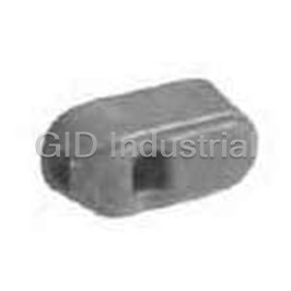
Switch Access Fusible Disconnect Switch Door Hardware BD3RL
Switch Access Disconnect Switch Auxiliary Contact BDAUX4
Switch Access Fusible Disconnect Switch Door Hardware BDDHK
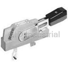
Switch Access Fusible Disconnect Switch Handle BDFHNHS12
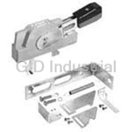
Switch Access Fusible Disconnect Switch Handle BDFHNHS4
Switch Access Fusible Disconnect Switch Shaft BDFHS12
Request a Quote

The quote request has been received
Close

Facing challenges or have inquiries? Feel free to contact us!
Call Us +1-469-283-2440
What they say about us
FANTASTIC RESOURCE
One of our top priorities is maintaining our business with precision, and we are constantly looking for affiliates that can help us achieve our goal. With the aid of GID Industrial, our obsolete product management has never been more efficient. They have been a great resource to our company, and have quickly become a go-to supplier on our list!
Bucher Emhart Glass
EXCELLENT SERVICE
With our strict fundamentals and high expectations, we were surprised when we came across GID Industrial and their competitive pricing. When we approached them with our issue, they were incredibly confident in being able to provide us with a seamless solution at the best price for us. GID Industrial quickly understood our needs and provided us with excellent service, as well as fully tested product to ensure what we received would be the right fit for our company.
Fuji
HARD TO FIND A BETTER PROVIDER
Our company provides services to aid in the manufacture of technological products, such as semiconductors and flat panel displays, and often searching for distributors of obsolete product we require can waste time and money. Finding GID Industrial proved to be a great asset to our company, with cost effective solutions and superior knowledge on all of their materials, it’d be hard to find a better provider of obsolete or hard to find products.
Applied Materials
CONSISTENTLY DELIVERS QUALITY SOLUTIONS
Over the years, the equipment used in our company becomes discontinued, but they’re still of great use to us and our customers. Once these products are no longer available through the manufacturer, finding a reliable, quick supplier is a necessity, and luckily for us, GID Industrial has provided the most trustworthy, quality solutions to our obsolete component needs.
Nidec Vamco
TERRIFIC RESOURCE
This company has been a terrific help to us (I work for Trican Well Service) in sourcing the Micron Ram Memory we needed for our Siemens computers. Great service! And great pricing! I know when the product is shipping and when it will arrive, all the way through the ordering process.
Trican Well Service
GO TO SOURCE
When I can't find an obsolete part, I first call GID and they'll come up with my parts every time. Great customer service and follow up as well. Scott emails me from time to time to touch base and see if we're having trouble finding something.....which is often with our 25 yr old equipment.
ConAgra Foods