

 Manufacturers
EATON BUSSMANN NDN111-WH-UL

Description
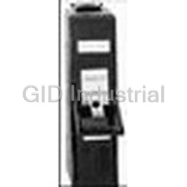
Terminal Blocks With High Short-Circuit Current 90 Amp
NDN111-WH-UL
Part Number
NDN111-WH-UL
Price
Request Quote
Manufacturer
EATON BUSSMANN
Lead Time
Request Quote
Category
Thermal Management » Misc Products
Specifications
Manufacturer
Eaton Bussmann
Manufacturers Part #
NDN111-WH-UL
Industry Aliases
NDN111-WH-UL
Sub-Categories
Miscellaneous Tools and Supplies
Factory Pack Quantity
100
Datasheet

Extracted Text
Power Distribution Blocks & Terminal Blocks with High Short-Circuit Current Ratings Table of Contents Page Selection Table . ........................... 2 Power Distribution Blocks PDBFS Series . . . . . . . . . . . . . . . . . . . . . . . . . . . . . . . . . . . .3-8 PDB Series . . . . . . . . . . . . . . . . . . . . . . . . . . . . . . . . . . . . . 9-12 Terminal Blocks 16XXX Series. . . . . . . . . . . . . . . . . . . . . . . . . . . . . . . . . . .13-15 14002-3-UL, TB300-03SP-UL, NDN63-WH-UL, NDN111-WH-UL . . . . . . . . . . . . . . . . . . . . . . . . . . . . . . . .16-18 Application Notes . . . . . . . . . . . . . . . . . . . . . . . .19-23 TOOLS TO ASSIST Technical Assistance Panel Layout 2D and 3D CAD files for some products to facilitate panel Application Engineering layouts found at www.cooperbussmann.com Application Engineering assistance is available to customers. The Application Engineering team is staffed by Engineering Services for SCCR engineers and available by phone with technical and OSCAR™ Compliance Software Eliminates the Guesswork in application support Monday – Friday, 8:00 a.m. – 5:00 p.m. Assembly Short-Circuit Current Rating (SCCR) Calculations. Central Time. The Cooper Bussmann innovative OSCAR™ Compliance Application Engineering can be reached via phone, fax or Software assists customer compliance with new Code and standards requirements for short-circuit current ratings as they email: relate to industrial control panels, equipment and assemblies. • Phone: 636-527-1270 Go to www.cooperbussmann.com • Fax: 636-527-1607 • E-mail: fusetech@cooperbussmann.com SCCR Panel Design Review for Improving Your Assembly SCCR. If your SCCR needs improvement, contact the Cooper Bussmann team for a design review. We guarantee our panel Online Resources SCCR review service for UL508A Supplement SB pre-certifica- Visit www.cooperbussmann.com for the following tion. resources: • Arc-flash calculator Other Application Information on SCCR • OSCAR™ compliance software Publications: • Training modules • Advanced Guide To Understanding Assembly Short-Circuit Current Rating Services • Simplified Guide To Understanding Short-Circuit Current • Engineering Rating – Find It, Fix It, Forget it • Training • SPD (Selecting Protective Devices) Sections on Industrial • Testing Control Panels and also Conductor & Terminations. Contact us for more information on Services: • Phone: 636-207-3294 • E-mail: services@cooperbussmann.com 1011 SB-BU09622 Page 1 of 23 Data Sheet 1049 Selection Table for SCCR Power Distribution Blocks and Terminal Blocks Short-Circuit Current Rated Power Distribution Control Panels. Marking the SCCR on Industrial Control ® Blocks Panels (NEC 409.110), Industrial Machinery Electrical ® ® Cooper Bussmann offers three distinctly different styles of Panels (NEC 670.3(A)), and HVAC equipment (NEC short-circuit current rated power distribution blocks (PDBs) 440.4(B)) is now required by the National Electrical Code. and terminal blocks (TBs) to match different application PDBs or TBs not marked with a SCCR are typically one of needs. The differences are whether the power the weakest links and may limit an assembly to no more than distribution blocks are enclosed or not, and whether they are 10kA SCCR. The PDBFS and PDB Series have increased UL1953 Listed PDBs or UL1059 Recognized TBs, which have spacing required where used in feeder circuits in equipment different minimum spacing requirements. The table on this listed to UL508A (UL1059 TBs must be evaluated for proper page can assist in the selection of the right series for your spacings). Also, for building wiring systems, the PDBFS application requirements. Series and PDB Series power distribution blocks can be used ® to meet the new 2005 NEC requirements in section Why these are important? 376.56(B) for PDBs in wireways. Assembly short-circuit current ratings (SCCRs) are now More application information on pages 19-23. ® required in the 2005 NEC and UL508A Listed Industrial Selection Table Industrial Industrial Control Control HVAC Wireways ® Product Catalog High Spacing** Panels Panels UL NEC Page UL Enclosed SCCR* 1” Air UL 508A UL 508A 1995 376.56(B) 2” Surface Branch Feeder (Requires Circuit Circuit UL 1953) † Series PDBFS 3 UL 1953 Listed Yes Yes Yes Yes Yes Yes Yes Power Distribution Blocks Yes UL 1953 Listed Series PDB 9 No*** Yes Yes Yes Yes Yes w/optional Power Distribution Blocks cover Series UL 1059 Recognized 16XXX 13 Terminal Blocks No*** Yes No**** Yes No**** Yes No NDN63-WH-UL, NDN111-WH-UL, UL 1059 Recognized 16 No Yes No Yes No Yes No 14002-3-UL, Terminal Blocks TB300-03SP-UL †IP-20 finger-safe under specific conditions, see datasheet page 8. *When protected by proper fuse class with maximum ampere rating specified or smaller. ** See PDB Spacing Requirements for Equipment table below. ***Optional covers are available. Not IP-20, but provide a safety benefit. ****No, except: Yes, if single pole units installed with proper spacings. PDB & TB Minimum Spacing Series PDB Requirements for Equipment Series PDBFS Spacing between Spacing between live parts of live parts and UL Standard opposite polarity grounded parts or enclosure Through air Over surface @600V @600V @600V 508A Feeder 1 2 1 ˝ ˝ ˝ Circuits 508A Branch 3 1 1 ⁄8˝ ⁄2˝ ⁄2˝ Circuits 3 1 1 1995 HVAC ⁄ ˝ ⁄ ˝ ⁄ ˝ 8 2 2 Note: Refer to Specific UL standards for complete spacing details. Series 162 and 163 Magnum Terminal Blocks 1011 SB-BU09622 Page 2 of 23 Data Sheet 1049 Series PDBFS Enclosed Power Distribution Blocks Feature/Benefits Electrical • Enclosed for enhanced • 600Vac or dc (UL 1953), 690Vac or dc (IEC) safety; IP-20 finger-safe • Short-Circuit Current Ratings up to 200kA, see table below under specific conditions, • Ampacities up to 760 Amps see page 8 • 75ºC rated connectors 2 • High Short-Circuit Current • CU Wire range 14 AWG to 500 kcmil or 2.5 to 240 mm Ratings up to 200,000A: Mechanical PDBs do not have to be • DIN rail or panel mount; PDBFS330 & PDBFS504 panel a weak link in achieving a mount only high SCCR for an • Captive termination screws; screws do not get misplaced industrial control panel • Wire ready: captive termination screws shipped backed out • Suitable for installation in to save time on conductor installation wireways and industrial • Sliding DIN rail latch for easy mounting control panel feeder and branch circuits. Listed to UL1953 • Single pole, gang mountable for multiple pole applications which has minimum spacing requirements at 600V of at least with interlocking dovetail accessory (optional Part 2A1279) 1” through air and 2” over surface One pin interlocks two units, two pins to interlock three units • Small footprint saves panel space. Stack side by side and still (see illustration on page 6) meet 1˝ and 2˝ spacing requirements • Flammability, UL 94V0 • For 2D and 3D CAD drawings visit www.cooperbussmann.com • Tin-plated AL connectors suitable for CU conductors • Elongated hole for panel mounting; easier mounting with Agency/Standards greater flexibility in matching up with drilled panel holes • UL Listed 1953, Guide QPQS, File E256146 • DIN rail end anchors required to prevent damage to block • CSA Certified, Class 6228-01, File 15364 when torquing, anchors not offered by Cooper Bussmann • CE component IEC 60947-7-1 • IEC 60529, IP-20 (Finger Safe) under specific conditions, see page 8 Series PDBFS Terminal Copper Conductor Capability Short-Circuit Current Rating Data Electrical Line Load Configuration Conductors Max Fuse Class & Amp** Catalog Number Openings per Pole Line Load J T RK1 RK5 Amps Wire Range Wire Range SCCR (All Single AWG or AWG or LPJ JJS LPS-RK FRS-R Pole) Line Load kcmil kcmil JJN LPN-RK FRN-R 2/0 to 8 AWG 2/0 to 8 AWG PDBFS204 175A 2/0 to 8 2/0 to 8 200 200 100 60 200kA 2 2 70 to 10 mm 70 to 10 mm 4 to 12 200 200 100 60 200kA 2/0 to 8 AWG 4 to 14 AWG PDBFS220 175A 2/0 to 8 175 175 100 30 100kA 2 2 70 to 10 mm 25 to 2.5 mm 4 to 14 200 200 100 60 50kA 350kcmil to 6 AWG 350kcmil to 6 AWG PDBFS303 310A 350 to 6 350 to 6 400 400 200 100 200kA 2 2 150 to 16 mm 150 to 16 mm 2 to 6 400 400 200 100 200kA 500kcmil to 6 AWG 2 to 14 AWG PDBFS330 380A 500 to 6 200 200 100 60 50kA 2 2 2 to 14 240 to 16 mm 35 to 2.5 mm 175 175 100 30 100kA 300 4 to 8 600 600 400 200 200kA 300kcmil to 4 AWG 4 to 14 AWG PDBFS377 570A 4 400 400 200 100 100kA 2 2 300 to 4 150 to 12 mm 25 to 2.5 mm 4 to 14 200 200 100 60 50kA 350kcmil to 4 AWG 350kcmil to 4 AWG 350 to 4 350 to 4 600 600 400 200 200kA PDBFS500 620A 2 2 185 to 12 mm 185 to 12 mm 500 500 600 800* 600 200 200kA 500kcmil to 6 AWG 500kcmil to 6 AWG PDBFS504 760A 2 2 240 to 16 mm 240 to 16 mm 500 to 6 500 to 6 600 600 400 200 100kA Ampacities 75C per NEC® Table 310.16 and UL508A Table 28.1 *Class L 800A (KRP-C 800_SP) or less fuses suitable for this particular SCCR case. ** Class G 60A (SC-60) or less or Class CC 30A (LP-CC-30, FNQ-R-30, KTK-R-30) or less are suitable for all SCCRs in this table. 1011 SB-BU09622 Page 3 of 23 Data Sheet 1049 Series PDBFS Enclosed Power Distribution Blocks Dimensions in[mm] Width Length Height Item Part No. A B C D E F G H 1 PDBFS204 1.030[26.16] 3.372[94.80] 2.146[54.50] 3.550[90.17] 2.905[73.79] 0.197[5.00] 0.197[5.00] N/A 2 PDBFS220 1.030[26.16] 3.372[94.80] 2.146[54.50] 3.550[90.17] 2.905[73.79] 0.197[5.00] 0.197[5.00] N/A 3 PDBFS303 1.550[39.37] 4.665[118.50] 2.874[73.00] 4.475[113.67] 3.810[96.77] 0.197[5.00] 0.236[6.00] N/A 4 PDBFS330 1.550[39.37] 4.665[118.50] 2.950[74.93] 4.475[113.67] 3.810[96.77] 0.197[5.00] 0.236[6.00] N/A 5 PDBFS377 1.875[47.62] 4.665[118.50] 2.933[74.50] 4.475[113.67] 3.810[96.77] 0.197[5.00] 0.236[6.00] N/A 6 PDBFS520 2.380[60.45] 4.665[118.50] 2.598[66.00] 4.475[113.67] 3.810[96.77] 0.197[5.00] 0.236[6.00] N/A 7 PDBFS504 2.560[65.02] 4.665[118.50] 3.150[80.00] 4.475[113.67] 3.810[96.77] 0.197[5.00] 0.236[6.00] 46.00[1.811] PDBFS204 PDBFS220 C PDBFS303 PDBFS330 1011 SB-BU09622 Page 4 of 23 Data Sheet 1049 Series PDBFS Enclosed Power Distribution Blocks PDBFS377 PDBFS500 PDBFS504 1011 SB-BU09622 Page 5 of 23 Data Sheet 1049 Series PDBFS Enclosed Power Distribution Blocks Panel Mounting Capable on all part numbers Use 2 screws for mounting each pole (#10 or M5 screw) (4 screws for PDBFS504) OR Hook load side onto 35mm DIN RAIL Open the latch using screwdriver Close the latch DIN Rail anchors are required on each DIN Rail Mounting side of block or blocks. Anchors must be used to prevent PDBFS204, PDBFS220, PDBFS303, damage to the plastic housing when PDBFS377, and PDBFS500 only. tightening terminals. Rotate PDB down For interlocking two or more blocks on a DIN Rail, insert male dove tail part number 2A1279 into the female dove tail opening. Fully insert male dove tail to interlock blocks. 2A1279 accessory ordered separately. 1011 SB-BU09622 Page 6 of 23 Data Sheet 1049 Series PDBFS Enclosed Power Distribution Blocks Series PDBFS Line Load Part Number Torque Trim Length Torque Trim Length Hex Key CU Wire Range CU Wire Range Hex Key Lb-in (Nm) in (mm) Lb-in (Nm) in (mm) 2/0 to 8 AWG 2/0 to 8 AWG PDBFS204 110 (12.4) 0.850 (21.6) 3/16˝ 110 (12.4) 0.970 (24.6) 3/16˝ 2 2 70 to 10mm 70 to 10mm 4 to 6 AWG 35 (4.0) 2 25 to 16mm 2/0 to 8 AWG 8 AWG 0.550 (14.0) top row, PDBFS220 120 (13.6) 0.750 (19.0) 3/16˝ 25 (2.8) 1/8˝ 2 2 70 to 10mm 10mm 0.850 (21.6) bottom row 10 to 14 AWG 20 (2.3) 2 6 to 2.5mm 350 Kcmil to 6 AWG 350 Kcmil to 6 AWG PDBFS303 275 (31.1) 1.350 (34.3) 5/16˝ 275 (31.1) 1.250 (31.8) 5/16˝ 2 2 150 to 16mm 150 to 16mm 2 to 3 AWG 50 (5.7) 2 35mm 4 to 6 AWG 45 (5.1) 2 PDBFS330 500 Kcmil to 6 AWG 500 (56.5) 1.250 (31.8) 3/8˝ 25 to 16mm 0.590 (15.0) top row 1/8˝ 2 240 to 16mm 8 AWG 1.200 (30.5) bottom row 40 (4.5) 2 10mm 10 to 14 AWG 35 (4.0) 2 6 to 2.5mm 4 to 6 AWG 35 (4.0) 2 25 to 16mm 300 Kcmil to 4 AWG 1.15 (29.2) top row 8 AWG 0.550 (14.0) top row, PDBFS377 275 (31.1) 1/4˝ 25 (2.8) 1/8˝ 2 2 150 to 25mm 1.400 (35.6) bottom row 10mm 1.00 (25.4) middle row 10 to 14 AWG 1.220 (31.0) bottom row 20 (2.3) 2 6 to 2.5mm 350 Kcmil to 4 AWG 350 Kcmil to 4 AWG PDBFS500 275 (31.1) 1.250 (31.8) 5/16˝ 275 (31.1) 1.250 (31.8) 5/16˝ 2 2 185 to 25mm 185 to 25mm 500 Kcmil to 6 AWG 500 Kcmil to 6 AWG PDBFS504 500 (56.5) 1.250 (31.8) 3/8˝ 500 (56.5) 1.250 (31.8) 3/8˝ 2 2 240 to 16mm 240 to 16mm Trim Wire Connector Hole Diameter Part No. Minimum Enclosure Part Line Load Size Number in (mm) in (mm) PDBFS204 16˝ X 16˝ X 6.75˝ PDBFS204 0.450 (11.5) 0.450 (11.5) PDBFS220 16˝ X 16˝ X 6.75˝ PDBFS220 0.450 (11.5) 0.246 (6.25) PDBFS303 36˝ X 30˝ X 12.625˝ PDBFS303 0.720 (18.3) 0.720 (18.3) PDBFS330 24˝ X 20˝ X 6.75˝ PDBFS330 0.870 (22.1) 0.314 (8.0) PDBFS377 24˝ X 20˝ X 6.75˝ PDBFS377 0.687 (17.5) 0.265 (6.7) PDBFS500 36˝ X 30˝ X 12.625˝ PDBFS500 0.718 (18.2) 0.718 (18.2) PDBFS504 36˝ X 30˝ X 12.625˝ PDBFS504 0.875 (22.2) 0.875 (22.2) 1011 SB-BU09622 Page 7 of 23 Data Sheet 1049 Series PDBFS Enclosed Power Distribution Blocks Specific Conditions to Achieve IP-20 Finger-Safe Status for Series PDBFS Line Load IP-20 IP-20 Part Trim Length Installed Wire Conductor Screw Trim Length Installed Wire Conductor Screw Number in (mm) Openings Opening in (mm) Openings Opening 2/0 to 8 AWG 2/0 to 8 AWG PDBFS204 0.850 (21.6) Yes Yes 0.970 (24.6) Yes Yes 2 2 70 to 10mm 70 to 10mm 4 to 14 AWG Yes Yes 2 2/0 to 8 AWG 0.550 (14.0) 25 to 2.5mm 2 PDBFS220 0.750 (19.0) 70 to 10mm Yes Yes top row, screws fully N/A Yes 0.850 (21.6) opened bottom row no wire in hole No N/A 350 Kcmil to 2/0 AWG 350 Kcmil to 2/0 AWG Yes Yes Yes Yes 2 2 150 to 70mm 1.250 (31.8) 150 to 70mm PDBFS303 1.350 (34.3) 1/0 to 6 AWG 1/0 to 6 AWG No Yes No Yes 2 2 50 to 16mm 50 to16mm 500 to 250 Kcmil 2 to 14 AWG Yes Yes Yes Yes 2 2 240 to 150mm 0.590 (15.0) 35 to 2.5mm PDBFS330 1.250 (31.8) 4/0 to 6 AWG top row, screws fully N/A Yes No Yes 120 to 16mm2 1.200 (30.5) opened bottom row no wire in hole No N/A 300 Kcmil to 4/0 AWG Yes Yes 2 150 to 120mm 0.550 (14.0) 4 to 14 AWG Yes Yes 2 1.15 (29.2) top row, 3/0 to 4 AWG top row, 25 to 2.5mm No Yes 2 PDBFS377 1.400 (35.6) bottom 95 to 25mm 1.00 (25.4) row screws fully middle row, screws fully N/A Yes N/A No opened 1.220 (31.0) opened bottom row no wire in hole no wire in hole No N/A Yes N/A 350 Kcmil to 2/0 AWG 350 Kcmil to 2/0 AWG Yes Yes Yes Yes 2 2 185 to 70mm 185 to 70mm 1/0 to 4 AWG 1/0 to 4 AWG No Yes No Yes 2 2 PDBFS500 1.250 (31.8) 50 to 25mm 1.250 (31.8) 50 to 25mm screws fully screws fully N/A No N/A No opened opened no wire in hole No N/A no wire in hole No N/A 500 to 350 Kcmil 500 to 350 Kcmil Yes Yes Yes Yes 2 2 240 to 185mm 240 to 185mm 300 Kcmil to 6 AWG 300 Kcmil to 6 AWG No Yes No Yes 2 2 PDBFS504 1.250 (31.8) 150 to 16mm 1.250 (31.8) 150 to 16mm screws fully screws fully N/A No N/A No opened opened no wire in hole No N/A no wire in hole No N/A 1011 SB-BU09622 Page 8 of 23 Data Sheet 1049 Series PDB Power Distribution Blocks Agency/Standards • UL Listed 1953, Guide QPQS, File E256146 Electrical • 600Vac or dc (UL 1953) • Short-Circuit Current Ratings up to 200kA, see table • 75ºC rated connectors, ampacities up to 310A • Wire range 14 AWG to 350 kcmil CU • Spacing between uninsulated opposite polarities or ground meets UL 1953 which requires at least 1” through air and 2” over surface for 301 to 600V Feature/Benefits • High Short-Circuit Current Ratings up to 200kA Mechanical PDBs do not have to be a weak link in achieving high • Panel mount SCCR for an industrial control panel • Flammability, UL 94V0 • Suitable for installation in wireways (with optional covers) • Tin-plated AL connectors suitable for CU conductors and industrial control panel feeder and branch circuits. Listed to UL1953 which has minimum spacing requirements at 600V of at least 1” through air and 2” Series PDB Terminal Copper Conductor Capability Short-Circuit Current Rating Data Line Load Configuration Conductors Max Fuse Class & Amp** Part Openings per Pole Line Load J T RK1 RK5 Number Amps Wire Range Wire Range SCCR AWG or AWG or LPJ JJS LPS-RK FRS-R Line Load kcmil kcmil JJN LPN-RK FRN-R PDB204-1 175A 2/0 to 8 AWG 2/0 to 8 AWG 2/0 to 8 2/0 to 8 200 200 200 60 200kA PDB204-3 4 to 12 200 200 200 60 200kA PDB220-1 175A 2/0 to 8 AWG 4 to 14 AWG 2/0 to 8 4 to 14 175 175 100 60 100kA PDB220-3 PDB280-1 175A 2/0 to 8 AWG 1/4-20 X 3/4 STUD 2/0 to 8 Stud 200 200 100 60 200kA PDB280-3 PDB321-1 4 to 12 400 400 200 100 200kA PDB321-2 175A 2/0 to 8 AWG 4 to 14 AWG 2/0 to 8 4 to 12 175 175 100 60 100kA PDB321-3 4 to 8 400 400 200 100 200kA PDB323-1 310A 350kcmil to 4 AWG 4 to 12 AWG 350 to 4 PDB323-3 4 to 12 175 175 100 60 100kA 4 to 8 400 400 200 100 200kA PDB370-1 310A 350kcmil to 4 AWG 4 to 14 AWG 350 to 4 PDB370-3 4 to 14 175 175 100 60 100kA 1/0 to 6 400 400 200 100 200kA PDB371-1 (6) 2 to 12 AWG 310A 350kcmil to 4 AWG 350 to 4 PDB371-3 (3) 1/0 to 12 1/0 to 12 175 175 100 60 100kA Ampacities 75C per NEC® Table 310.16 and UL508A Table 28.1 ** Class G 60A (SC-60) or less or Class CC 30A (LP-CC-30, FNQ-R-30, KTK-R-30) or less are suitable for all SCCR in this table. These blocks available in 1 or 3 poles. PDB321 available in 1, 2, and 3 poles. Part Number: Example: PDB204-1 = single pole PDB204-3 = three pole 1011 SB-BU09622 Page 9 of 23 Data Sheet 1049 Series PDB Power Distribution Blocks Dimensions in [mm] Width Length Height Part Numbers ABCD E F (Hole) PDB204-3, PDB220-3, PDB280-3 4.27 [108.3] 2.88 [73.2] 2.13 [54.0] 1.62 [41.1] 2.25 [57.2] 0.22 [5.7] PDB323-3, PDB370-3, PDB371-3 6.00 [152.4] 5.50 [139.7] 3.70 [93.9] 3.25 [82.6] 4.75 [120.7] 0.22 [5.7] PDB323-1, PDB370-1, PDB371-1 1.96 [49.8] 3.38 [85.7] 3.32 [85.7] — 0.21 [2.5] X 0.41 [10.4] PDB204-1, PDB220-1, PDB280-1 1.07 [27.2] 2.88 [73.2] 1.75 [44.5] 2.25 [57.2] 0.20 [5.1] PDB321-1 1.96 [49.8] 4.00 [101.6] 3.32 [84.3] 1.62 [41.1] 3.37 [85.6] 0.21 [5.3] X 0.41 [10.4] PDB321-2 3.58 [90.9] 4.00 [101.6] 3.32 [84.3] 1.62 [41.1] 3.37 [85.6] 0.21 [5.3] X 0.41 [10.4] PDB321-3 5.20 [132.1] 4.00 [101.6] 3.32 [84.3] 1.62 [41.1] 3.37 [85.6] 0.21 [5.3] X 0.41 [10.4] Top Top Side Side PDB204-3, PDB220-3, PDB280-3 PDB323-1, PDB370-1, PDB371-1 Top PDB323-3, PDB370-3, PDB371-3 Side Side F PDB204-1, C PDB321-1, PDB321-2, PDB321-3 PDB220-1, PDB280-1 1011 SB-BU09622 Page 10 of 23 Data Sheet 1049 Series PDB Power Distribution Blocks Optional covers Covers are ordered for each individual pole, i.e. three 1-pole covers for 3-pole block, see table A. Except PDB321 blocks have one cover for 1, 2 or 3 pole versions, see table B. (Shipped with mounting screws) Table A Table B Block Cover Block Cover PDB2XX-(pole): CPB162-1 PDB321-1 CPDB-1 PDB3XX-(pole): CPDB-1 PDB321-2 CPDB-2 PDB321-3 CPDB-3 Series 163 Cover Series 162 Cover Supplied with (4) #4 thread-cutting screws assembled as shown 4.14" Textured surface for marking CPDB-1 (single pole) 2.10" CPDB-2 (two pole) 3.72" CPDB-3 (three pole) 5.34" Flat Cover Part Number ˝A˝ Dimension CPB162-1 0.94˝ CPB162-2 1.75˝ CPB162-3 2.56˝ Part No. Minimum Enclosure Size PDB204-1, -3 16˝ X 16˝ X 6.75˝ PDB220-1, -3 16˝ X 16˝ X 6.75˝ PDB280-1, -3 16˝ X 16˝ X 6.75˝ PDB321-1, -2, -3 24˝ X 20˝ X 6.75˝ PDB323-1, -3 24˝ X 20˝ X 6.75˝ PDB370-1, -3 24˝ X 20˝ X 6.75˝ PDB371-1, -3 24˝ X 20˝ X 6.75˝ 1011 SB-BU09622 Page 11 of 23 Data Sheet 1049 Series PDB Power Distribution Blocks Line Load Part Number Torque Trim Length Hex Key CU Wire Range Torque Trim Length Hex Key, CU Wire Range Lb-in (Nm) in (mm) Lb-in (Nm) in (mm) Slot, Stud 2/0 to 8 AWG 2/0 to 8 AWG PDB204-1, -3 110 (12.4) 0.700 (17.8) 3/16˝ 110 (12.4) 0.700 (17.8) 3/16˝ Hex 2 2 70 to 10mm 70 to 10mm 4 to 6 AWG 35 (4.0) 2 25 to 16mm 2/0 to 8 AWG 8 AWG 0.470 (11.9) top row, PDB220-1, -3 120 (13.6) 0.670 (17.0) 3/16˝ 25 (2.8) Slot 2 2 70 to 10mm 10mm 0.780 (19.8) bottom row 10 to 14 AWG 20 (2.3) 2 6 to 2.5mm 2/0 to 8 AWG 1/4 - 20 PDB280-1, -3 120 (13.6) 0.670 (17.0) 3/16˝ N/A 50 (5.7) N/A 70 to 10mm2 Stud 4 to 6 AWG 35 (4.0) 2 25 to 16mm 2/0 to 8 AWG 8 AWG 0.480 (12.2) top row, PDB321-1, -2, -3 120 (13.6) 0.700 (17.8) 3/16˝ 25 (2.8) Slot 2 2 70 to 10mm 10mm 0.800 (20.3) bottom row 10 to 14 AWG 20 (2.3) 2 6 to 2.5mm 4 to 6 AWG 35 (4.0) 2 25 to 16mm 350 Kcmil to 4 AWG 8 AWG 1.00 (25.4) top row, PDB323-1, -3 275 (31.1) 0.900 (22.9) 5/16˝ 25 (2.8) Slot 2 2 185 to 25mm 10mm 0.450 (11.43) bottom row 10 to 12 AWG 20 (2.3) 2 6 to 4mm 4 to 6 AWG 35 (4.0) 2 25 to 16mm 0.450 (11.4) top row 350 Kcmil to 4 AWG 8 AWG PDB370-1, -3 275 (31.1) 0.900 (22.9) 5/16˝ 25 (2.8) 0.630 (16.0) middle row, Slot 2 2 185 to 25mm 10mm 0.920 (23.4) bottom row 10 to 14 AWG 20 (2.3) 2 6 to 2.5mm 2 to 3 AWG 50 (5.7) 2 35mm 4 to 6 AWG 45 (5.1) 0.450 (11.4) top row Slot top row 2 PDB371-1, -3 350 Kcmil to 4 AWG 275 (31.1) 0.900 (22.9) 5/16˝ 25 to 16mm 0.630 (16.0) middle row, Slot middle row, 2 185 to 25mm 8 AWG 40 (4.5) 0.920 (23.4) bottom row 3/16˝ Hex 2 10mm bottom row 10 to 12 AWG 35 (4.0) 2 6 to 4mm Trim Top Row Top Row Top Row Middle Row Bottom Row Bottom Row Bottom Row PDB220-1, -3 PDB321-1, -2, -3 PDB370-1, -3 PDB323-1, -3 PDB371-1, -3 1011 SB-BU09622 Page 12 of 23 Data Sheet 1049 Series 16XXX Terminal Blocks Feature/Benefits Mechanical • High Short-Circuit Current Ratings up to 200kA • Panel mount • UL1059 Recognition • Flammability, UL 94V0 • Tin-plated AL connectors suitable for CU Agency/Standards conductors • UL 1059 Recognized, Guide XCFR2, File E221592 • General Industry Class per UL 1059, usage catagory C • CSA Certified, Class 6228-01, File 15364 Electrical • 600Vac or dc • Short Circuit Current Ratings up to 200kA, see table • Ampacities up to 310 Amps • 75ºC rated connectors • Wire range 14 AWG to 350 kcmil CU Series 162 and 163 Series 16XXX Terminal Copper Conductor Capability Short-Circuit Current Rating Data Line Load Configuration Conductors Max Fuse Class & Amp** Part Openings per Pole Line Load J T RK1 RK5 Number Amps Wire Range Wire Range SCCR AWG or AWG or LPJ JJS LPS-RK FRS-R Line Load kcmil kcmil JJN LPN-RK FRN-R 16204-1, 175A 2/0 to 8 AWG 2/0 to 8 AWG 2/0 to 8 2/0 to 8 200 200 200 60 200kA -2, -3 -2, -3 4 to 12 200 200 200 60 200kA 16220-1, 175A 2/0 to 8 AWG 4 to 14 AWG 2/0 to 8 -2, -3 4 to 14 175 175 100 60 100kA 16280-1, 175A 2/0 to 8 AWG 1/4-20 X 3/4 STUD 2/0 to 8 Stud 200 200 100 60 200kA -2, -3 4 to12 400 400 200 100 200kA 16321-1, 175A 2/0 to 8 AWG 4 to 14 AWG 2/0 to 8 -2, -3 4 to 12 175 175 100 60 100kA 4 to 8 400 400 200 100 200kA 16323-1, 310A 350kcmil to 4 AWG 4 to 12 AWG 350 to 4 -2, -3 4 to 12 175 175 100 60 100kA 4 to 8 400 400 200 100 200kA 16370-1, 310A 350kcmil to 4 AWG 4 to 14 AWG 350 to 4 -2, -3 -2, -3 4 to 14 175 175 100 60 100kA 1/0 to 6 400 400 200 100 200kA 16371-1, (6) 2 to 12 AWG 310A 350kcmil to 4 AWG 350 to 4 -2, -3 (3) 1/0 to 12 1/0 to 12 175 175 100 60 100kA Ampacities 75C per NEC® Table 310.16 and UL508A Table 28.1 ** Class G 60A (SC-60) or less or Class CC 30A (LP-CC-30, FNQ-R-30, KTK-R-30) Part No. Minimum Enclosure or less are suitable for all the SCCRs in this table. Size These blocks available in 1, 2, or 3 poles Part Number: 16204-1, -2, -3 16˝ X 16˝ X 6.75˝ Example: 16204-1 = single pole 16220-1, -2, -3 16˝ X 16˝ X 6.75˝ 16204-3 = three pole 16280-1, -2, -3 16˝ X 16˝ X 6.75˝ 16321-1, -2, -3 24˝ X 20˝ X 6.75˝ 16323-1, -2, -3 24˝ X 20˝ X 6.75˝ 16370-1, -2, -3 24˝ X 20˝ X 6.75˝ 16371-1, -2, -3 24˝ X 20˝ X 6.75˝ 1011 SB-BU09622 Page 13 of 23 Data Sheet 1049 Series 16XXX Terminal Blocks Series 16XXX-X Line Load Part Number Torque Trim Length Hex Key CU Wire Range Torque Trim Length Hex Key, CU Wire Range Lb-in (Nm) in (mm) Lb-in (Nm) in (mm) Slot, Stud 2/0 to 8 AWG 2/0 to 8 AWG 16204-1, -2, -3 110 (12.4) 0.700 (17.8) 3/16˝ 110 (12.4) 0.700 (17.8) 3/16˝ Hex 2 2 70 to 10mm 70 to 10mm 4 to 6 AWG 35 (4.0) 2 25 to 16mm 2/0 to 8 AWG 8 AWG 0.470 (11.9) top row, 16220-1, -2, -3 120 (13.6) 0.670 (17.0) 3/16˝ 25 (2.8) Slot 2 2 70 to 10mm 10mm 0.780 (19.8) bottom row 10 to 14 AWG 20 (2.3) 2 6 to 2.5mm 2/0 to 8 AWG 1/4 - 20 16280-1, -2, -3 120 (13.6) 0.670 (17.0) 3/16˝ N/A 50 (5.7) N/A 70 to 10mm2 Stud 4 to 6 AWG 35 (4.0) 2 25 to 16mm 2/0 to 8 AWG 8 AWG 0.480 (12.2) top row, 16321-1, -2, -3 120 (13.6) 0.700 (17.8) 3/16˝ 25 (2.8) Slot 2 2 70 to 10mm 10mm 0.800 (20.3) bottom row 10 to 14 AWG 20 (2.3) 2 6 to 2.5mm 4 to 6 AWG 35 (4.0) 2 25 to 16mm 350 Kcmil to 4 AWG 8 AWG 1.00 (25.4) top row, 16323-1, -2, -3 275 (31.1) 0.900 (22.9) 5/16˝ 25 (2.8) Slot 2 2 185 to 25mm 10mm 0.450 (11.43) bottom row 10 to 12 AWG 20 (2.3) 2 6 to 4mm 4 to 6 AWG 35 (4.0) 2 25 to 16mm 0.450 (11.4) top row 350 Kcmil to 4 AWG 8 AWG 16370-1, -2, -3 275 (31.1) 0.900 (22.9) 5/16˝ 25 (2.8) 0.630 (16.0) middle row, Slot 2 2 185 to 25mm 10mm 0.920 (23.4) bottom row 10 to 14 AWG 20 (2.3) 2 6 to 2.5mm 2 to 3 AWG 50 (5.7) 2 35mm 4 to 6 AWG Slot top row 45 (5.1) 0.450 (11.4) top row 2 16371-1, -2, -3 350 Kcmil to 4 AWG 275 (31.1) 0.900 (22.9) 5/16˝ 25 to 16mm Slot middle row, 0.630 (16.0) middle row, 2 185 to 25mm 8 AWG 3/16˝ Hex 40 (4.5) 0.920 (23.4) bottom row 2 10mm bottom row 10 to 12 AWG 35. (4.0) 2 6 to 4mm Trim Top Row Top Row Top Row Middle Row Bottom Row Bottom Row Bottom Row 16220-1, -2, -3 16321-1, -2, -3 16370-1, -2, -3 16323-1, -2, -3 16371-1, -2, -3 1011 SB-BU09622 Page 14 of 23 Data Sheet 1049 Series 16XXX Terminal Blocks Dimensions for Series 162 & 163 (Inches) Width Length Height Part No. A1 A2 A3 B C D E F G H J K L 162 1.06 1.88 2.60 2.85 1.75 0.81 2.25 0.53 0.31 0.84 0.31 0.20 0.42 163 1.96 3.58 5.20 4.0 3.32 1.62 3.37 — — — — Slot 0.20˝ wide x 0.41˝ long Slot 0.42˝ wide x 0.62˝ long Series 162 Series 163 (Available 1, 2, and 3 pole) (Available 1, 2, and 3 pole) HJ LINE SIDE C Side A F D D E B F C K Dia. G L C'Bore LOAD SIDE Optional covers Block Cover Series 162: CPD162-(pole)* Series 163: CPDB-(pole)* *Provided with mounting screws Series 163 Cover Series 162 Cover Supplied with (4) #4 thread-cutting screws assembled as shown 4.14" Textured surface for marking Part Number ˝A˝ Dimension CPB162-1 0.94˝ CPB162-2 1.75˝ CPDB-1 (single pole) 2.10" CPDB-2 (two pole) 3.72" CPB162-3 2.56˝ CPDB-3 (three pole) 5.34" Flat Cover 1011 SB-BU09622 Page 15 of 23 Data Sheet 1049 Terminal Blocks With High Short-Circuit Current Ratings Short-Circuit Current Rating Data Max. Fuse Class and Amp** CU Wire Torque (1) CU Wire J T RK1 RK5 Minimum Part Number Amps Range lb-in Range SCCR Enclosure JJS LPS-RK FRS-R Line & Load MAX. AWG LPJ Size JJN LPN-RK FRN-R 2 to 3 AWG 50 2 to 8 200 200 100 60 200kA 4 to 6 AWG 45 14002-3-UL 115 8 AWG 35 2 to 14 175 175 100 60 100kA 8˝ x 8˝ x 4˝ 10 to 14 AWG 35 TB300-03SP-UL 30 10 to 18 AWG 16 10 to 18 60 60 60 — 100kA 8˝ x 8˝ x 4˝ NDN63-WH-UL 65 6 to 18 AWG 35 6 to 18 100 100 60 30 100kA 8˝ x 8˝ x 4˝ NDN111-WH-UL 90 2 to 18 AWG 32 2 to 18 200 200 200 60 100kA 8˝ x 8˝ x 4˝ **Class G 60A (SC-60) or less or Class CC 30A (LP-CC-30, FNQ-R-30, KTK-R-30) or less are suitable for all SCCRs in this table 14002-3-UL 2.375 Barrier Terminal Block (60.32) 0.875 Agency/Standards (22.23) • UL 1059 Recognized, Guide XCFR2, File E62622 • General Industry Class per UL 1059, usage category C 0.375 (9.52) Electrical • 600Vac or dc 0.750 • Short-Circuit Current Rating up to 200kA, See table (19.05) • 75ºC rated connectors, 115A ampacity • Wire range 2 to 4 AWG CU Mechanical • Panel mount 0.625 • 3 pole configuration (15.88) • Flammability, UL94 HB 1.250 (31.75) 1011 SB-BU09622 Page 16 of 23 Data Sheet 1049 Terminal Blocks With High Short-Circuit Current Ratings NDN63-WH-UL Agency/Standards • UL 1059 Recognized, Guide XCFR2, File E62622 • General Industry Class per UL 1059, usage category C Electrical • 600Vac or dc • Short-Circuit Current Rating up to 100kA, See table page 16 • 65A ampacity • Wire range 6 to 18 AWG CU Mechanical • 35mm DIN rail and C-rail mount • .375˝ (9.52) pole to pole spacing 1.50 • 3 pole configuration (38.10) 1 • Marking tape MT12- ⁄2 1.67 • Flammability, UL94 V2 (42.41) 1.17 1.45 (29.71) (36.83) TB300-03SP-UL 8-32 binding head screw - TB 300 Double Row Terminal Block 2.25 (57.15) Agency/Standards • UL 1059 Recognized, Guide XCFR2, File E62622 .22 2.69 • General Industry Class per UL 1059, usage category C (5.6) (68.32) Electrical • 600Vac or dc .90 1.33 .50 (12.7) • Short-Circuit Current Rating up to 100kA, See table page 16 (22.8) (33.8) • 30A ampacity • Wire range 10 to 18 AWG CU .56 Mechanical .21 x .25 slots (14.2) • Panel mount .56 (5.3 x 6.3) • .562˝ (14.28) pole to pole spacing .21dia. (14.2) • 3 pole configuration (5.3) .412 • Flammability, UL94 V0 (10.4) .81 (20.5) .33 (8.4) 1011 SB-BU09622 Page 17 of 23 Data Sheet 1049 Terminal Blocks With High Short-Circuit Current Ratings NDN111-WH-UL Agency/Standards • UL 1059 Recognized, Guide XCFR2, File E62622 • General Industry Class per UL 1059, usage category C Electrical • 600Vac or dc • Short-Circuit Current Rating up to 100kA, See table page 16 • 90A ampacity • Wire range 2 to 18 AWG CU Mechanical • Panel mount • 35mm DIN rail and C-rail mount • .635˝ (16.13mm) pole to pole spacing • 3 pole configuration 1 • Marking tape MT12- ⁄2 • Flammability, UL94 V2 Mtg. holes .18 (4.57) dia. .28 (7.11) c'bores 1.46 (37.13) 1.71 (43.48) Dovetail .62 Option (15.75) 1.87 (47.50) 1.44 (36.57) 1011 SB-BU09622 Page 18 of 23 Data Sheet 1049 Application Notes Proper Application there is adequate spacing for the OEM application in which When applying Power Distribution Blocks (PDBs) and they are being applied. Power distribution blocks are terminal blocks, there are several requirements that must be evaluated to UL1953, the power distribution block outline of ® satisfied, based upon various UL Standards, the NEC , and investigation and are listed for general installation, which the specific application. Some of the requirements and ratings means they have adequate spacing for most OEM and field include: voltage, continuous current, wire range (load and line applications. These power distribution blocks are marked with side), conductor terminal temperature rating, short-circuit a listing mark, which means that the inspector does not need current rating or withstand rating (SCCR), type and amp to check ”conditions of acceptability” as is needed with rating of upstream overcurrent protective device (fuse or recognized products. As listed products, PDBs evaluated to circuit breaker) and spacing (between uninsulated live part UL1953 are suitable for use in the field. For example, an and uninsulated grounded part or uninsulated live parts of electrical contractor may install them in a metal wireway, opposite polarity). The requirements vary, based on the something that may not be done with a recognized product application for industrial control panels (feeder circuit or such as a terminal block. branch circuit), field applications, or HVAC applications. Marking Equipment with SCCR ® New requirements in the 2005 NEC for a marked short- Marking the equipment with its short-circuit current rating circuit current rating (SCCR) on industrial control panels (SCCR) is another important consideration in the proper ® ® (NEC 409.110), industrial machinery (NEC 670.3A), and application of PDBs and terminal blocks. This datasheet ® commercial/industrial HVAC equipment (NEC 440.4(B)) have provides the details on Cooper Bussmann power distribution resulted in considerable attention being placed upon the blocks and terminal blocks that have high short-circuit proper selection and application of power distribution blocks current ratings. Using these PDBs and terminal blocks with and terminal blocks. In addition, UL508A Industrial Control appropriate overcurrent protective devices makes it easier to Panels has a requirement that the assembly be marked with achieve a high short-circuit current rating for the entire panel its short-circuit current rating. Per UL508A, each power assembly. circuit component in the panel, such as a PDB, has a SCCR expressed in amperes or kiloamperes and voltage. The SCCR for Wire Management Products SCCR shall be established by either being marked on the There are different ways to determine the SCCR for wire product, the instruction sheet provided with it, or from management products (power distribution blocks, terminal UL508A Supplement SB Table SB4.1. If an assembly short- blocks and multi-lug connectors) per UL508A Supplement SB: circuit current rating above 10,000 amperes is desired, a (1) Use tested and listed combinations, which consist of a power distribution block or a terminal block with a high specific part number and a specific type and maximum size short-circuit current rating must normally be utilized. overcurrent protective device. For instance, the power distribution blocks in this datasheet are all SCCR tested and The following material includes some application notes on listed combinations with fuses. An upstream current-limiting power distribution block and terminal block SCCR, UL Listed fuse of a specific class and maximum ampere rating as 1953 vs UL Recognized 1059, spacing requirements, shown in the tables can be used to achieve the SCCR in the conductor ampacities, conductor termination ratings affecting tables. Otherwise, the SCCR of the power distribution block conductor ratings, and SCCR for multi-lug switches and will be determined by (2) or (3). circuit breakers. Combination SCCRs UL Listed 1953 vs. UL Recognized 1059 Up to 200KA Listed products simply require checking to ensure that the product is used in accordance with its listing and labeling. However, for recognized products, such as terminal blocks, Use Tables the “Conditions of Acceptability” must be investigated to Specified fuse class ensure the product is suitable for the specific application, and with amp rating no then the procedure description must be documented in the greater than maximum shown manufacturer’s procedure for the assembly. Most power distribution blocks available today are actually terminal blocks, and are recognized to UL 1059, the terminal block standard. Terminal blocks may or may not meet the spacing needed for OEM applications. Terminal blocks are marked with a UL recognition mark to ensure that the designer and UL inspector checks, among other things, that 1011 SB-BU09622 Page 19 of 23 Data Sheet 1049 Application Notes (2) UL508A has provisions to raise the rating of power Spacing between Spacing between distribution blocks by the use of current-limiting live parts of live parts and UL Standard opposite polarity grounded parts overcurrent protective devices such as current-limiting or enclosure Through air Over surface fuses (i.e. class J, T, RK1, etc.) in the feeder portion of the @600V @600V @600V circuit. 508A Feeder (3) If the SCCR rating for a power distribution block, terminal 1˝ 2˝ 1˝ Circuits block or multi-lug connector is not established by (1) or (2) 508A Branch 3 1 1 ⁄8˝ ⁄2˝ ⁄2˝ above, then the SCCR is the default 10kA per UL508A, Circuits 3 1 1 Supplement SB, Table SB4.1. 1995 HVAC ⁄ ˝ ⁄ ˝ ⁄ ˝ 8 2 2 Note: Refer to Specific UL standards for complete spacing details. For more in depth application material on SCCR see Industrial Control Panel section of publication SPD or Industrial Control Panels (UL508A): Advanced Guide To Understanding Assembly Short-Circuit UL508A contains three important requirements to consider Current Rating. when applying power distribution blocks. • Spacing of 1˝ through air, 2˝ over surface (301 to 600V) is SCCR for Multi-Lug Connector (Power Distribution required when used in a feeder circuit (that’s everything Lug) Switch and Circuit Breaker ahead of or on the line side of the final branch circuit Switches or circuit breakers with multi-lug connectors for overcurrent protective device). conductor terminations serve a very similar wire management • An assumed short-circuit current rating of 10kA for power function as power distribution blocks. However, it cannot be distribution and terminal blocks not marked with a higher assumed that when a multi-lug connector is installed on a short-circuit current rating, per UL508A Table SB4.1. circuit breaker or switch, that the SCCR of the multi-lug • Conductor ampacity requirements based on conductor connector is the same as the interrupting rating of the terminal temperature ratings and UL508A conductor protective device. Multi-lug connectors are covered under UL ampacities Standard 486 A/B. Much like a power distribution block, The following details the requirements regarding the use of multi-lug connectors are components for distributing tap power distribution blocks in industrial control panels. conductors to power loads and are not an integral part of the overcurrent protective device operation. Therefore, the Use of Power Distribution Blocks in Industrial Control multi-lug connector must be evaluated in a short-circuit test Panel Feeder Circuits (600V & below) with the specific overcurrent protective device and listed with • A Listed PDB (UL1953) can be used “as is” since it meets a specific combination SCCR. It is important to note, most the 2˝ and 1˝ spacing requirements for feeder circuits in switches and circuit breakers are not short-circuit tested with UL508A section 10.2 (see Table 10.2) & 28.2.4. multi-lug connectors. If a multi-lug connector on a circuit • A Recognized Terminal Block (UL1059) can only be used if breaker or switch does not have a combination SCCR with it meets the spacing requirements in UL508A sections 10.2 the specific overcurrent protective device used, then it is to (see Table 10.2) & 28.2.1 and it is suitable for field wiring be treated in the same manner as an unmarked power (use Group A, C or D of UL 1059). distribution block, which means the SCCR is the default 10kA – Use Group A: Service — including dead-front switch (UL508A, Supplement SB). To repeat, unless the switch or boards, panelboards, service equipment, and the like. circuit breaker with a multi-lug connector is specifically – Use Group B: Commercial appliances, including marked with a short-circuit current rating, the actual short- business equipment, electronic data processing circuit current rating is 10,000 amperes (or less, if the equipment, and the like. interrupting rating of the circuit breaker or fuse is less than – Use Group C: Industrial, general. 10,000 amperes). The use of a listed and tested combination – Use Group D: Industrial, devices having limited ratings. SCCR will ensure that a higher rating is achieved for the Such as where the load on any single circuit of the product and aid in achieving a higher overall SCCR for the terminal block does not exceed 15 amperes at 51 to industrial control panel. 150 volts, 10 amperes at 151 to 300 volts, 5 amperes at 301 to 600 volts, or the maximum ampere rating, PDB Spacing Requirements for Equipment: whichever is less. Depending upon the specific application and the standard to Listed PDBs have adequate spacing for feeder which the equipment is being designed, there are certain circuit applications but most recognized terminal PDBs that can meet these spacing requirements, some with a blocks don’t have the spacing required high SCCR. The following details the spacing requirements at for use in feeder circuits 600V based upon the equipment standards. 1011 SB-BU09622 Page 20 of 23 Data Sheet 1049 Application Notes Use of Power Distribution Blocks in Industrial Control Termination Ratings Panel Branch Circuits (600V & below) Important considerations in the electrical and thermal • A Listed PDB (UL1953) can be used “as is” since it exceeds relationship for components in a circuit are the conductor the spacing requirements for branch circuits in UL508A size, material, rated ampacity, conductor insulation section 10.2 (see table 10.1) & 28.2.4. temperature rating and the permissible connector device • A Recognized Terminal Block (UL1059) can only be used if conductor temperature limits. it meets the spacing requirements at the required voltage in UL 508A, section 10.2 (see Table 10.1) & 28.2.1 and it is If a conductor terminates at two devices that have conductor suitable for field wiring (Use Group A, C or D of UL 1059). terminations rated at two different temperatures, the conductor ampacity must correlate to the terminal with the lowest temperature rating. Listed PDBs have adequate spacing for branch circuit applications and most recognized terminal 60°C terminal 75°C terminal blocks are also adequate for branch circuit applications Power Distribution Block Application Examples – UL 508A Conductor size and insulation rating? Conductors with higher temperature ratings can be used at their rated ampacities if the terminations of the circuit devices are rated for the higher temperature rated conductor [NEC 110.14(C)(1)(a)(3)]. However, the industry norm is that most devices rated 100A or less, such as blocks, disconnects, controllers and circuit breakers, have 60°C or 75°C rated terminations. For circuits greater than 100A, the norm is 75°C terminations. UL508A has further internal wiring restrictions requiring 90°C insulated conductors, but these conductors are sized based on either 60ºC or 75ºC allowable ampacities. PDB in UL 508A, 480V Feeder Circuit must have spacing of 1˝ through air and 2˝ Terminations have a temperature rating that must be over suface. PDBs listed to UL 1953 meet these spacing requirements. Terminal Blocks recognized to UL 1059 must be verified to have required spacing. observed and this has implications on permissible conductor temperature rating and ampacity. Shown below are three common termination ratings and the rules. The conductor ampacity may also have to be derated due to ambient, conduit fill or other reasons. Terminal Temp Rating 60°C, 75°C, 90°C or higher temperature rated conductor can be used, but the ampacity of the 60°C conductor must be based as if conductor is rated 60°C. 75°C, 90°C or higher temperature rated conductor can be used, but the ampacity of the conductor must 75°C be based as if conductor is rated 75°C. A 60°C conductor is not permitted to be used. Dual temperature rated termination. Either 60°C conductors at 60°C ampacity or 75°C conductors at 75°C ampacity can be used. If 90°C or higher 3 1 PDB in UL508A, 480V Branch Circuit must have spacing of ⁄8˝ through air and ⁄2˝ 60°C/75°C temperature rated conductor is used, the ampacity of over surface. PDBs listed to UL 1953 meet these spacing as well as most the conductor must be based as if conductor is terminal blocks recognized to UL 1059. rated 75°C. 1011 SB-BU09622 Page 21 of 23 Data Sheet 1049 Application Notes For more information on this see section Conductor & HVAC Equipment (UL1995): Terminations – Application Considerations in the Cooper The electrical panel is required to be marked with the ® Bussmann publication SPD – Selecting Protective Devices on assembly SCCR per NEC 440.4(B). The larger spacing that www.cooperbussmann.com is mandated in UL508A is not present in UL1995. If the control panel for the HVAC equipment is a listed UL508A UL 508A Industrial Control Panels Conductors for panel, then the larger UL508A spacing is required. Internal Wiring: Copper conductors only. Conductors are sized based on either the 60°C or 75°C allowable conductor Power Distribution Block Application UL 1995 ampacities from UL508A, Table 28.1 (following). The 75°C Example ampacities can only be used if the termination temperature ratings at both ends of the conductor are rated 75°C or 60°C/75°C. In addition, the conductor insulation is required to be 90°C or higher temperature rated even though the ampacity is based on 60°C or 75°C (UL508A, 29.2.1 & 29.6.1(b)). UL508A, Table 28.1 (Partial) Wire size 60ºC (140ºF) 75ºC (167ºF) 2 AWG (mm ) Copper Copper 14 (2.1) 15 15 12 (3.3) 20 20 10 (5.3) 30 30 8 (8.4) 40 50 6 (13.3) 55 65 4 (21.2) 70 85 PDB in 480V UL 1995 HVAC Equipment must have spacing of 3/8˝ 3 (26.7) 85 100 through air and 1/2˝ over surface. PDBs listed to UL 1953 meet this spacing 2 (33.6) 95 115 as well as most terminal blocks recognized to UL 1059. 1 (42.4) 110 130 1/0 (53.5) – 150 2/0 (67.4) – 175 3/0 (85.0) – 200 4/0 (107.2) – 230 250 kcmil (127) – 255 300 (152) – 285 350 (177) – 310 400 (203) – 335 500 (253) – 380 600 (304) – 420 700 (355) – 460 750 (380) – 475 800 (405) – 490 900 (456) – 520 1000 (506) – 545 1250 (633) – 590 1500 (760) – 625 1750 (887) – 650 2000 (1013) – 665 NOTES 1 For multiple-conductors of the same size (1/0 AWG or larger) at a terminal, the ampacity is equal to the value in this table for that conductor multiplied by the number of conductors that the terminal is able to accommodate. 1011 SB-BU09622 Page 22 of 23 Data Sheet 1049 Application Notes ® New 2005 NEC Requirements For Wireways: Power Distribution Block Application Wireway UL1953 listed power distribution blocks are suitable for the Example ® new 2005 NEC requirement in section 376.56(B) for field installation in metal wireways, if they are the enclosed type (Series PDBFS) or open type with cover. UL1953 is explicit in paragraph 1.1 that these devices are used for splicing and tapping conductors in metallic wireways, junction boxes, auxilary gutters, etc. Listed devices can be field installed; however, recognized devices are not intended for field installation. UL1059 devices are recognized and are terminal blocks, not power distribution blocks. Therefore UL1059 devices are not suitable for field installation and are not suitable for metal wireway applications even if enclosed or with covers. Also, the SCCR rating of a power distribution block installed in a metal wireway shall be equal to or greater than the available short-circuit current at the point of ® application (NEC 110-10). ® National Electrical Code : 376.56(B) Power Distribution Blocks. “(1) Installation. Power distribution blocks installed in metal wireways shall be listed.” Series PDB (open style) with covers and Series PDBFS (enclosed style) are “(4) Live Parts. Power distribution blocks shall not have suitable for installation in metal wireways. exposed live parts in the wireway after installation.” ® When installed in metal wireways, the NEC now requires a power distribution block that is listed (acceptableto AHJ). It must be an enclosed PDB or equipped with a cover to prevent exposure of live parts. Series PDBFS (enclosed style) and Series PDB with optional covers are UL1953 Power Distribution Blocks and are suitable for metal wireway applications. Terminal blocks, UL1059 recognized devices, are not suitable for this application. 1011 SB-BU09622 Page 23 of 23 Data Sheet 1049
Frequently asked questions
How does Electronics Finder differ from its competitors?

Is there a warranty for the NDN111-WH-UL?
Which carrier will Electronics Finder use to ship my parts?
Can I buy parts from Electronics Finder if I am outside the USA?
Which payment methods does Electronics Finder accept?
Why buy from GID?

Quality
We are industry veterans who take pride in our work

Protection
Avoid the dangers of risky trading in the gray market

Access
Our network of suppliers is ready and at your disposal

Savings
Maintain legacy systems to prevent costly downtime

Speed
Time is of the essence, and we are respectful of yours
Related Products
Camaster HRC Fuse Holders 20BS
Pull Out With GFCI B222-60FGF
60A, Pull Out W/ 1/2in Cable Whip B222-60NF12W
60A, Pull Out W/ 3/4in Cable Whip B222-60NF34W
Cartridge Fuses 250Vac 50A Fast Acting BK/AGC-50
Battery Disconnect Switches Surge Protectors And Computer Memory BP/BMS-1
Request a Quote

The quote request has been received
Close

Facing challenges or have inquiries? Feel free to contact us!
Call Us +1-469-283-2440
What they say about us
FANTASTIC RESOURCE
One of our top priorities is maintaining our business with precision, and we are constantly looking for affiliates that can help us achieve our goal. With the aid of GID Industrial, our obsolete product management has never been more efficient. They have been a great resource to our company, and have quickly become a go-to supplier on our list!
Bucher Emhart Glass
EXCELLENT SERVICE
With our strict fundamentals and high expectations, we were surprised when we came across GID Industrial and their competitive pricing. When we approached them with our issue, they were incredibly confident in being able to provide us with a seamless solution at the best price for us. GID Industrial quickly understood our needs and provided us with excellent service, as well as fully tested product to ensure what we received would be the right fit for our company.
Fuji
HARD TO FIND A BETTER PROVIDER
Our company provides services to aid in the manufacture of technological products, such as semiconductors and flat panel displays, and often searching for distributors of obsolete product we require can waste time and money. Finding GID Industrial proved to be a great asset to our company, with cost effective solutions and superior knowledge on all of their materials, it’d be hard to find a better provider of obsolete or hard to find products.
Applied Materials
CONSISTENTLY DELIVERS QUALITY SOLUTIONS
Over the years, the equipment used in our company becomes discontinued, but they’re still of great use to us and our customers. Once these products are no longer available through the manufacturer, finding a reliable, quick supplier is a necessity, and luckily for us, GID Industrial has provided the most trustworthy, quality solutions to our obsolete component needs.
Nidec Vamco
TERRIFIC RESOURCE
This company has been a terrific help to us (I work for Trican Well Service) in sourcing the Micron Ram Memory we needed for our Siemens computers. Great service! And great pricing! I know when the product is shipping and when it will arrive, all the way through the ordering process.
Trican Well Service
GO TO SOURCE
When I can't find an obsolete part, I first call GID and they'll come up with my parts every time. Great customer service and follow up as well. Scott emails me from time to time to touch base and see if we're having trouble finding something.....which is often with our 25 yr old equipment.
ConAgra Foods