

 Manufacturers
EATON BUSSMANN SD14-101-R

Description
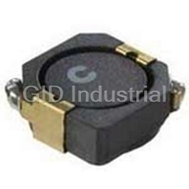
Inductor Power Shielded Drum Core 99.25uH/100uH 20% 100KHz Ferrite 386mA 1.68Ohm DCR 2020 T/R
SD14-101-R
Part Number
SD14-101-R
Price
Request Quote
Manufacturer
EATON BUSSMANN
Lead Time
Request Quote
Category
Magnetics » Inductor Surface Mount
Specifications
Manufacturer
Eaton Bussmann
Manufacturers Part #
SD14-101-R
Industry Aliases
SD14-101-R
Sub-Category
Surface Mount Inductors
Factory Pack Quantity
3800
Datasheet


Extracted Text
Effective August 2017 Technical Data PM4311 Supersedes March 2007 SD Low profile metalized shielded drum core power inductors Applications • Digital cameras • Media players • Mobile phones • Hand held equipment • PCMCIA cards • GPS systems Environmental data • Storage temperature range (component): -40 °C to +125 °C Product features • Operating temperature range: -40 °C to +125 °C • Six sizes of shielded drum core inductors (ambient plus self-temperature rise) with low profiles (as low as 1.0mm) and • Solder reflow temperature: high power density J-STD-020 (latest revision) compliant • Inductance range from .47 uH to 1000 uH HALOGEN • Current range from 0.88 A to 6.0 A Pb HF • Ferrite shielded, low EMI FREE • Ferrite core material SD Technical Data PM4311 Low profile metalized shielded drum core power inductors Effective August 2017 Product specifications Part Number Rated OCL (1) Part Irms (2) Isat (3) DCR (4) Volt Inductance +/-20% Marking (A) (A) (Ω) u-sec (µH) (µH) Typ. Typ. SD10-R47-R 0.470 0.453 A 2.59 3.54 0.0249 2.1 SD10-1R0-R 1.00 1.119 B 1.93 2.25 0.0448 3.3 SD10-1R5-R 1.50 1.563 C 1.60 1.91 0.0653 3.9 SD10-2R2-R 2.20 2.081 D 1.35 1.65 0.0912 4.5 SD10-3R3-R 3.30 3.339 E 1.24 1.31 0.1078 5.7 SD10-4R7-R 4.70 4.893 F 1.04 1.08 0.1535 6.9 SD10-6R2-R 6.20 6.743 G 0.94 0.92 0.218 8.1 SD10-8R2-R 8.20 8.889 H 0.800 0.800 0.2607 9.3 SD10-100-R 10.0 10.07 J 0.760 0.752 0.336 9.9 SD10-150-R 15.0 15.55 K 0.613 0.605 0.4429 12.3 SD10-220-R 22.0 22.21 L 0.498 0.506 0.6718 14.7 SD10-330-R 33.0 32.20 M 0.412 0.420 0.9807 17.7 SD10-470-R 47.0 46.63 N 0.337 0.349 1.47 21.3 SD10-680-R 68.0 70.01 O 0.301 0.285 1.84 26.1 SD10-820-R 82.0 83.48 P 0.258 0.261 2.50 28.5 SD10-101-R 100 102.0 Q 0.225 0.236 3.29 31.5 SD10-151-R 150 149.2 R 0.200 0.195 4.15 38.1 SD10-221-R 220 222.2 S 0.161 0.160 6.41 46.5 SD10-331-R 330 330.4 T 0.130 0.131 9.83 56.7 SD10-471-R 470 468.3 U 0.117 0.110 12.10 67.5 SD12-R47-R 0.470 0.490 A 3.19 3.86 0.0246 2.84 SD12-1R2-R 1.20 1.21 B 2.62 2.45 0.0366 4.47 SD12-1R5-R 1.50 1.69 C 2.19 2.08 0.0521 5.28 SD12-2R2-R 2.20 2.25 D 1.83 1.80 0.0747 6.09 SD12-3R3-R 3.30 3.61 E 1.55 1.42 0.1043 7.71 SD12-4R7-R 4.70 4.41 F 1.46 1.29 0.1177 8.53 SD12-6R2-R 6.20 6.25 G 1.21 1.08 0.1699 10.15 SD12-8R2-R 8.20 8.41 H 1.02 0.931 0.2399 11.77 10.0 10.89 J 0.938 0.818 0.2844 13.40 SD12-100-R SD12-150-R 15.0 15.21 K 0.782 0.692 0.4089 15.83 SD12-220-R 22.0 22.09 L 0.628 0.574 0.6338 19.08 SD12-330-R 33.0 32.49 M 0.519 0.474 0.9289 23.14 SD12-470-R 47.0 47.61 N 0.428 0.391 1.37 28.01 SD12-680-R 68.0 68.89 O 0.341 0.325 2.16 33.70 SD12-820-R 82.0 82.81 P 0.326 0.297 2.36 36.95 SD12-101-R 100 98.0 Q 0.308 0.273 2.64 40.19 SD12-151-R 150 151.3 R 0.251 0.220 3.96 49.94 SD12-221-R 220 222.0 S 0.229 0.181 4.76 60.49 SD12-331-R 330 334.9 T 0.186 0.148 7.25 74.30 SD12-471-R 470 462.3 U 0.167 0.126 8.95 87.29 SD12-681-R 680 670.8 V 0.149 0.104 11.30 105 SD12-821-R 820 800.9 W 0.129 0.095 14.93 115 SD12-102-R 1000 992.3 X 0.121 0.086 17.20 128 (1) Open Circuit Inductance Test Parameters: 100 kHz, 0.25 Vrms, 0.0 (4) DCR limits @ +20 °C. Adc. 5) Applied Volt-Time product (V-us) across the inductor at 100 kHz necessary to (2) RMS current for an approximate ΔT of 40 °C without core loss. It is generate a core loss equal to 10% of the total losses for 40 °C temperature rise. recommended that the temperature of the part not exceed +125 °C. (3) SD10,12,18,25 Peak current for approximate 30% rolloff at +20 °C. SD14 Peak current for approximate 20% roll off at +20 °C. www.eaton.com/electronics 2 SD Technical Data PM4311 Effective August 2017 Low profile metalized shielded drum core power inductors Product specifications Part Number Rated OCL (1) Part Irms (2) Isat (3) DCR (4) Volt Inductance +/-20% Marking (A) (A) (Ω) u-sec (µH) (µH) Typ. Typ. SD14-R58-R 0.58 0.61 A 3.52 4.84 0.0220 3.38 SD14-R87-R 0.87 0.88 B 3.2 3.96 0.0243 4.13 SD14-1R2-R 1.2 1.23 C 2.7 3.35 0.0344 4.88 SD14-1R5-R 1.5 1.63 D 2.53 2.91 0.0390 5.63 SD14-2R0-R 2 2.09 E 2.37 2.56 0.0445 6.38 SD14-2R5-R 2.5 2.62 F 2.05 2.29 0.0595 7.1 SD14-3R2-R 3.2 3.19 G 1.94 2.08 0.0663 7.9 SD14-4R5-R 4.5 4.53 H 1.64 1.74 0.0935 9.4 SD14-6R9-R 6.9 6.98 J 1.35 1.41 0.1363 11.6 SD14-8R8-R 8.8 8.88 K 1.14 1.25 0.1913 13.1 SD14-100-R 10 9.93 L 1.1 1.18 0.2058 13.9 SD14-150-R 15 14.68 M 0.98 0.969 0.2609 16.9 SD14-220-R 22 21.93 N 0.806 0.793 0.3853 20.6 SD14-330-R 33 32.55 O 0.654 0.651 0.5852 25.1 SD14-470-R 47 47.57 P 0.525 0.538 0.9055 30.4 SD14-680-R 68 68.21 Q 0.474 0.449 1.11 36 SD14-820-R 82 83 R 0.408 0.407 1.50 40 SD14-101-R 100 99.25 S 0.386 0.373 1.68 44 SD14-151-R 150 152.4 T 0.315 0.301 2.52 54 SD14-221-R 220 222 U 0.258 0.249 3.77 66 SD14-331-R 330 335.1 V 0.206 0.203 5.92 81 SD14-471-R 470 471.4 W 0.173 0.171 8.34 96 SD14-681-R 680 683.3 X 0.156 0.142 10.3 115 SD14-821-R 820 823.4 Y 0.134 0.129 13.9 126 SD14-102-R 1000 1008 Z 0.126 0.117 15.8 140 SD18-R47-R 0.47 0.49 A 3.58 4.63 0.0201 2.35 SD18-R82-R 0.82 0.81 B 3.24 3.60 0.0247 3.02 SD18-1R2-R 1.20 1.21 C 2.97 2.95 0.0294 3.70 SD18-1R5-R 1.50 1.69 D 2.73 2.49 0.0345 4.37 SD18-2R2-R 2.20 2.25 E 2.55 2.16 0.0398 5.04 SD18-3R3-R 3.30 3.61 F 2.07 1.71 0.0605 6.38 SD18-4R7-R 4.70 4.41 G 1.77 1.54 0.0824 7.06 SD18-6R2-R 6.20 6.25 H 1.61 1.30 0.1000 8.40 SD18-8R2-R 8.20 8.41 J 1.38 1.12 0.1351 9.74 SD18-100-R 10.0 10.89 K 1.28 0.982 0.1584 11.09 SD18-150-R 15.0 15.21 L 1.06 0.831 0.2278 13.10 SD18-220-R 22.0 22.09 M 0.876 0.689 0.3366 15.79 SD18-330-R 33.0 32.49 N 0.715 0.568 0.5057 19.15 SD18-470-R 47.0 47.61 O 0.578 0.470 0.7732 23.18 SD18-680-R 68.0 68.89 P 0.514 0.390 0.9798 27.89 SD18-820-R 82.0 82.81 Q 0.446 0.356 1.30 30.58 SD18-101-R 100 102.01 R 0.419 0.321 1.47 33.94 SD18-151-R 150 151.29 S 0.345 0.263 2.18 41.33 SD18-221-R 220 222.01 T 0.296 0.217 2.95 50.06 SD18-331-R 330 334.89 U 0.248 0.177 4.20 61.49 SD18-471-R 470 479.61 V 0.201 0.148 6.39 73.58 SD18-681-R 680 681.21 W 0.167 0.124 9.28 87.70 SD18-821-R 820 823.69 X 0.145 0.113 12.35 96.43 SD18-102-R 1000 1004 Y 0.136 0.102 14.01 107 (1) Open Circuit Inductance Test Parameters: 100 kHz, 0.25 Vrms, 0.0 (4) DCR limits @ +20 °C. Adc. 5) Applied Volt-Time product (V-us) across the inductor at 100 kHz necessary to (2) RMS current for an approximate ΔT of 40 °C without core loss. It is generate a core loss equal to 10% of the total losses for 40 °C temperature rise. recommended that the temperature of the part not exceed +125 °C. (3) SD10,12,18,25 Peak current for approximate 30% rolloff at +20 °C. SD14 Peak current for approximate 20% roll off at +20 °C. 3 www.eaton.com/electronics SD Technical Data PM4311 Low profile metalized shielded drum core power inductors Effective August 2017 Product specifications Part Number Rated OCL (1) Part Irms (2) Isat (3) DCR (4) Volt Inductance +/-20% Marking Amperes Amperes (Ω) u-sec (μH) (μH) Typ. Typ. SD20-R47-R 0.47 0.490 A 3.59 4.00 0.0200 2.28 SD20-1R2-R 1.20 1.21 B 3.07 2.55 0.0275 3.58 SD20-1R5-R 1.50 1.69 C 2.88 2.15 0.0312 4.23 SD20-2R2-R 2.20 2.25 D 2.45 1.87 0.0429 4.88 SD20-3R3-R 3.30 3.61 E 2.17 1.47 0.0547 6.18 SD20-4R7-R 4.70 4.41 F 2.05 1.33 0.0612 6.83 SD20-6R2-R 6.20 6.25 G 1.89 1.12 0.0720 8.13 SD20-8R2-R 8.20 8.41 H 1.61 0.966 0.1000 9.43 SD20-100-R 10.0 9.61 J 1.53 0.903 0.1100 10.08 SD20-150-R 15.0 15.21 K 1.25 0.718 0.1655 12.68 SD20-220-R 22.0 22.09 L 1.12 0.596 0.2053 15.28 SD20-330-R 33.0 32.49 M 0.913 0.491 0.3100 18.53 SD20-470-R 47.0 47.61 N 0.745 0.406 0.4650 22.43 SD20-680-R 68.0 68.89 O 0.610 0.337 0.6947 26.98 SD20-820-R 82.0 82.81 P 0.576 0.308 0.7785 29.58 SD20-101-R 100 98.01 Q 0.495 0.283 1.06 32.18 SD20-151-R 150 151.3 R 0.435 0.228 1.37 39.98 SD20-221-R 220 222.0 S 0.356 0.188 2.04 48.43 SD20-331-R 330 327.6 T 0.294 0.155 2.99 58.83 SD20-471-R 470 470.9 U 0.263 0.129 3.74 70.53 SD20-681-R 680 681.2 V 0.216 0.107 5.56 84.83 SD20-821-R 820 823.7 W 0.204 0.098 6.22 93.28 SD20-102-R 1000 1004.9 X 0.172 0.088 8.73 103 SD25-R47-R 0.47 0.466 A 3.88 6.00 0.0177 2.13 SD25-R82-R 0.82 0.770 B 3.58 4.67 0.0208 2.74 SD25-1R2-R 1.20 1.15 C 3.33 3.81 0.0240 3.34 SD25-1R5-R 1.50 1.61 D 3.12 3.23 0.0274 3.95 SD25-2R2-R 2.20 2.14 E 2.93 2.80 0.0311 4.56 SD25-3R3-R 3.30 3.43 F 2.64 2.21 0.0384 5.78 SD25-4R7-R 4.70 5.03 G 2.39 1.83 0.0467 6.99 SD25-6R8-R 6.80 6.93 H 2.19 1.56 0.0556 8.21 SD25-8R2-R 8.20 7.99 J 1.92 1.45 0.0724 8.82 SD25-100-R 10.0 10.35 K 1.80 1.27 0.0824 10.03 SD25-150-R 15.0 14.45 L 1.67 1.08 0.0956 11.86 SD25-220-R 22.0 22.81 M 1.34 0.857 0.1478 14.90 SD25-330-R 33.0 33.07 N 1.11 0.711 0.2149 17.94 SD25-470-R 47.0 47.89 O 0.919 0.592 0.3156 21.58 SD25-680-R 68.0 68.64 P 0.741 0.482 0.4850 25.84 SD25-820-R 82.0 82.17 Q 0.713 0.441 0.5242 28.27 SD25-101-R 100 100.79 R 0.670 0.398 0.5937 31.31 SD25-151-R 150 148.4 S 0.553 0.328 0.8723 38.00 SD25-221-R 220 222.4 T 0.446 0.268 1.34 46.51 SD25-331-R 330 332.2 U 0.359 0.219 2.07 56.85 SD25-471-R 470 472.4 V 0.293 0.184 3.10 67.79 SD25-681-R 680 677.2 W 0.262 0.154 3.88 81.17 SD25-821-R 820 826.7 X 0.230 0.139 5.04 89.68 SD25-102-R 1000 1003.4 Y 0.216 0.126 5.70 98.80 (1) Open Circuit Inductance Test Parameters: 100 kHz, 0.25 Vrms, 0.0 (4) DCR limits @ +20 °C. Adc. 5) Applied Volt-Time product (V-us) across the inductor at 100 kHz necessary to (2) RMS current for an approximate ΔT of 40 °C without core loss. It is generate a core loss equal to 10% of the total losses for 40 °C temperature rise. recommended that the temperature of the part not exceed +125 °C. (3) SD10,12,18,25 Peak current for approximate 30% roll off at +20 °C. SD14 Peak current for approximate 20% roll off at +20 °C. 4 www.eaton.com/electronics SD Technical Data PM4311 Effective August 2017 Low profile metalized shielded drum core power inductors Dimensions-mm RECOMMENDED PCB LAYOUT TOP VIEW 2 PAD LAYOUT 4 PAD LAYOUT SIDE VIEW BOTTOM VIEW Pin # 1 SCHEMATIC 1 identifier 1 5.950 9 5.95 9 1 2.975 5.2 R2.250 1.0 Max a 2 2.975 R2.250 1.5 Typ. 5.950 Ref. 2 2.975 2 Part marking (Note A) 2 2.575 2 HT 2 5.15 (see chart below) 5.2 Max A) Part Marking: Line 1: (1st digit indicates the inductance value per part marking Series HT designator in chart above) SD10 1.0mm max (2nd digit is a bi-weekly production date code) SD12 1.2mm max (3rd digit is the last digit of the year produced) Line 2: XX (indicates the product size code) SD14 1.45mm max SD18 1.8mm max Do not route traces or vias underneath the inductor SD20 2.0mm max SD25 2.5mm max Packaging Information 4.00 1.5 Dia SD10 2 2.00 ± 0.05 min. 1.5 Dia. A +0.1/-0.0 1.75 1 12.0 +/-0.3 0 B Bo ACTUAL SIZE 5.50 2 SD10 Ao=5.45mm Ko A Bo=5.45mm A Ao Parts packaged on 13" Diameter reel, 8.0 SECTION A-A Ko=1.20mm 3,800 parts per reel. Direction of feed 4.00 SD12/14/18 1.5 Dia 1.5 Dia. min. +0.1/-0.0 2.00 ± 0.05 1.75 A ACTUAL SIZE ACTUAL SIZE SD12 SD14 1 12.0 Bo +/-0.3 5.50 2 ACTUAL SIZE Ao=5.45mm SD18 Ko A Bo=5.45mm Ao Parts packaged on 13" Diameter reel, 8.0 SECTION A-A Ko=2.00mm 3,800 parts per reel. Direction of feed SD20/25 4.00 1.5 Dia 1.5 Dia. min. +0.1/-0.0 2.00 ± 0.05 1.75 A 1 12.0 B Bo +/-0.3 0 ACTUAL SIZE ACTUAL SIZE 5.50 2 SD20 SD25 Ao=5.45mm Ko A A Ao 8 8.0 0 Bo=5.45mm SECTION A-A Parts packaged on 13" Diameter reel, Direction of feed Ko=2.70mm 2,900 parts per reel. Dimensions are in millimeters. www.eaton.com/electronics 5 SD Technical Data PM4311 Low profile metalized shielded drum core power inductors Effective August 2017 Temperature rise vs current SD10-220 SD10-471 100.0 100.0 90.0 90.0 80.0 80.0 70.0 70.0 60.0 60.0 50.0 50.0 40.0 40.0 30.0 30.0 20.0 20.0 10.0 10.0 0.0 0.0 0.00 0.10 0.20 0.30 0.40 0.50 0.60 0.70 0.80 0.00 0.05 0.09 0.14 0.18 0.23 Idc (A) Idc (A) SD12-470 SD12-330 100.0 100.0 90.0 90.0 80.0 80.0 70.0 70.0 60.0 60.0 50.0 50.0 40.0 40.0 30.0 30.0 20.0 20.0 10.0 10.0 0.0 0.0 0.00 0.10 0.20 0.30 0.40 0.50 0.60 0.70 0.80 0.00 0.10 0.20 0.30 0.40 0.50 0.60 0.70 Idc (A) Idc (A) SD14-102 SD14-150 100.0 100.0 90.0 90.0 80.0 80.0 70.0 70.0 60.0 60.0 50.0 50.0 40.0 40.0 30.0 30.0 20.0 20.0 10.0 10.0 0.0 0.0 0.00 0.20 0.40 0.60 0.80 1.00 1.20 1.40 0.000 0.020 0.040 0.060 0.080 0.100 0.120 0.140 0.160 0.180 0.200 Idc (A) Idc (A) SD18-100 SD18-101 100.0 100.0 90.0 90.0 80.0 80.0 70.0 70.0 60.0 60.0 50.0 50.0 40.0 40.0 30.0 30.0 20.0 20.0 10.0 10.0 0.0 0.0 0.00 0.10 0.20 0.30 0.40 0.50 0.60 0.70 0.80 0.0 0.2 0.4 0.6 0.8 1.0 1.2 1.4 1.6 1.8 2.0 Idc (A) Idc (A) SD20-100 SD20-101 100.0 100.0 90.0 90.0 80.0 80.0 70.0 70.0 60.0 60.0 50.0 50.0 40.0 40.0 30.0 30.0 20.0 20.0 10.0 10.0 0.0 0.0 0.0 0.4 0.8 1.2 1.6 2.0 2.4 0.00 0.10 0.20 0.30 0.40 0.50 0.60 0.70 0.80 Idc (A) Idc (A) 6 www.eaton.com/electronics Temperature Rise (Deg. C) Temperature Rise (Deg. C) Temperature Rise (Deg. C) Temperature Rise (Deg. C) Temperature Rise (Deg. C) Temperature Rise (Deg. C) Temperature Rise (Deg. C) Temperature Rise (Deg. C) Temperature Rise (Deg. C) Temperature Rise (Deg. C) SD Technical Data PM4311 Effective August 2017 Low profile metalized shielded drum core power inductors Temperature rise vs current SD25-100 SD25-101 100.0 100.0 90.0 90.0 80.0 80.0 70.0 70.0 60.0 60.0 50.0 50.0 40.0 40.0 30.0 30.0 20.0 20.0 10.0 10.0 0.0 0.0 0.0 0.5 1.0 1.5 2.0 2.5 3.0 0.00 0.20 0.40 0.60 0.80 1.00 1.20 Idc (A) Idc (A) Inductance Characteristics OCL vs Isat OCL vs Isat SD12 SD10 100 100 90 90 80 80 70 70 60 60 50 50 40 40 30 30 20 20 10 10 0 0 0 10 20 30 40 50 60 70 80 90 100 110 120 130 140 0 10 20 30 40 50 60 70 80 90 100 110 120 % of Isat % of Isat OCL vs Isat OCL vs Isat SD18 SD14 100 100 90 90 80 80 70 70 60 60 50 50 40 40 30 30 20 20 10 10 0 0 0 10 20 30 40 50 60 70 80 90 100 110 120 130 0 10 20 30 40 50 60 70 80 90 100 110 120 130 140 150 160 % of Isat % of Isat OCL vs Isat OCL vs Isat SD20 SD25 100 100 90 90 80 80 70 70 60 60 50 50 40 40 30 30 20 20 10 10 0 0 0 10 20 30 40 50 60 70 80 90 100 110 120 130 140 150 0 10 20 30 40 50 60 70 80 90 100 110 120 130 140 150 160 170 % of Isat % of Isat www.eaton.com/electronics 7 OCL (%) OCL (%) OCL (%) Temperature Rise (Deg. C) OCL (%) OCL (%) OCL (%) Temperature Rise (Deg. C) SD Technical Data PM4311 Low profile metalized shielded drum core power inductors Effective August 2017 Core loss Irms DERATING WITH CORE LOSS % of applied volt u-seconds www.eaton.com/electronics 8 % of Losses from Irms (maximum) SD Technical Data PM4311 Effective August 2017 Low profile metalized shielded drum core power inductors Solder Reflow Profile TP Table 1 - Standard SnPb Solder (T ) Table 1 - Standard SnPb Solder (T ) T -5°C c c C t Max. Ramp Up Rate = 3°C/s P Volume Volume Max. Ramp Down Rate = 6°C/s 3 3 Package mm mm _ Thickness <350 >350 T L <2.5mm 235°C 220°C Preheat t A _ >2.5mm 220°C 220°C T smax T Taabbllee 2 2 - - L Leeaadd ((P Pbb)) F Fr reeee S So ollddeer r ((T T )) c c Volume Volume Volume T smin 3 3 3 t s Package mm mm mm Thickness <350 350 - 2000 >2000 <1.6mm 260°C 260°C 260°C 1.6 – 2.5mm 260°C 250°C 245°C >2.5mm 250°C 245°C 245°C 25°C Time 25°C to Peak Time Reference JDEC J-STD-020 Profile Feature Standard SnPb Solder Lead (Pb) Free Solder Preheat and Soak Temperature min. (T ) 100°C 150°C smin T emperature max. (T ) 150°C 200°C smax Time (T to T ) (t ) 60-120 Seconds 60-120 Seconds smin smax s Average ramp up rate T to T 3°C/ Second Max. 3°C/ Second Max. smax p Liquidous temperature (TL) 183°C 217°C Time at liquidous (t ) 60-150 Seconds 60-150 Seconds L Peak package body temperature (T )* Table 1 Table 2 P Time (t )** within 5 °C of the specified classification temperature (T ) 20 Seconds** 30 Seconds** p c Average ramp-down rate (T to T ) 6°C/ Second Max. 6°C/ Second Max. p smax Time 25°C to Peak Temperature 6 Minutes Max. 8 Minutes Max. * Tolerance for peak profile temperature (T ) is defined as a supplier minimum and a user maximum. p ** Tolerance for time at peak profile temperature (t ) is defined as a supplier minimum and a user maximum. p Life Support Policy: Eaton does not authorize the use of any of its products for use in life support devices or systems without the express written approval of an officer of the Company. Life support systems are devices which support or sustain life, and whose failure to perform, when properly used in accordance with instructions for use provided in the labeling, can be reasonably expected to result in significant injury to the user. Eaton reserves the right, without notice, to change design or construction of any products and to discontinue or limit distribution of any products. Eaton also reserves the right to change or update, without notice, any technical information contained in this bulletin. Eaton Electronics Division 1000 Eaton Boulevard Cleveland, OH 44122 United States www.eaton.com/electronics © 2017 Eaton Eaton is a registered trademark. All Rights Reserved Printed in USA All other trademarks are property Publication No. PM4311 of their respective owners. August 2017 Temperature
Frequently asked questions
How does Electronics Finder differ from its competitors?

Is there a warranty for the SD14-101-R?
Which carrier will Electronics Finder use to ship my parts?
Can I buy parts from Electronics Finder if I am outside the USA?
Which payment methods does Electronics Finder accept?
Why buy from GID?

Quality
We are industry veterans who take pride in our work

Protection
Avoid the dangers of risky trading in the gray market

Access
Our network of suppliers is ready and at your disposal

Savings
Maintain legacy systems to prevent costly downtime

Speed
Time is of the essence, and we are respectful of yours
Related Products
Inductor Power Shielded Wirewound 10uH 30% 100KHz Ferrite 4A 35mOhm DCR T/R CD1-100
Inductor Power Shielded Wirewound 10uH 30% 100KHz Ferrite 4A 35mOhm DCR T/R CD1-100-R
Inductor Power Shielded Wirewound 100uH 30% 100KHz Ferrite 1.36A 304mOhm DCR T/R CD1-101
Inductor Power Shielded Wirewound 100uH 30% 100KHz Ferrite 1.36A 304mOhm DCR T/R CD1-101-R
Inductor Power Shielded Wirewound 15uH 30% 100KHz Ferrite 3.35A 50mOhm DCR T/R CD1-150
Inductor Power Shielded Wirewound 15uH 30% 100KHz Ferrite 3.35A 50mOhm DCR T/R CD1-150-R


Request a Quote

The quote request has been received

Close

Facing challenges or have inquiries? Feel free to contact us!
Call Us +1-469-283-2440
What they say about us
FANTASTIC RESOURCE
One of our top priorities is maintaining our business with precision, and we are constantly looking for affiliates that can help us achieve our goal. With the aid of GID Industrial, our obsolete product management has never been more efficient. They have been a great resource to our company, and have quickly become a go-to supplier on our list!
Bucher Emhart Glass
EXCELLENT SERVICE
With our strict fundamentals and high expectations, we were surprised when we came across GID Industrial and their competitive pricing. When we approached them with our issue, they were incredibly confident in being able to provide us with a seamless solution at the best price for us. GID Industrial quickly understood our needs and provided us with excellent service, as well as fully tested product to ensure what we received would be the right fit for our company.
Fuji
HARD TO FIND A BETTER PROVIDER
Our company provides services to aid in the manufacture of technological products, such as semiconductors and flat panel displays, and often searching for distributors of obsolete product we require can waste time and money. Finding GID Industrial proved to be a great asset to our company, with cost effective solutions and superior knowledge on all of their materials, it’d be hard to find a better provider of obsolete or hard to find products.
Applied Materials
CONSISTENTLY DELIVERS QUALITY SOLUTIONS
Over the years, the equipment used in our company becomes discontinued, but they’re still of great use to us and our customers. Once these products are no longer available through the manufacturer, finding a reliable, quick supplier is a necessity, and luckily for us, GID Industrial has provided the most trustworthy, quality solutions to our obsolete component needs.
Nidec Vamco
TERRIFIC RESOURCE
This company has been a terrific help to us (I work for Trican Well Service) in sourcing the Micron Ram Memory we needed for our Siemens computers. Great service! And great pricing! I know when the product is shipping and when it will arrive, all the way through the ordering process.
Trican Well Service
GO TO SOURCE
When I can't find an obsolete part, I first call GID and they'll come up with my parts every time. Great customer service and follow up as well. Scott emails me from time to time to touch base and see if we're having trouble finding something.....which is often with our 25 yr old equipment.
ConAgra Foods