

 Manufacturers
EBM-PAPST INC. 78137-2-4039

Description
Thrml Mgmt Access Grill Guard 560mm Steel Wire
78137-2-4039
Part Number
78137-2-4039
Price
Request Quote
Manufacturer
EBM-PAPST INC.
Lead Time
Request Quote
Category
Thermal Management » Thermal Management Accessories
Specifications
Manufacturer
ebm-papst Inc.
Manufacturers Part #
78137-2-4039
Sub-Category
Thermal Management Accessories
Factory Pack Quantity
1
Datasheet

Extracted Text
version 2013-02 EC centrifugal fans – RadiPac The engineer’s choice RadiPac: Everything packed in compact form The line of radial plug fans with GreenTech EC motor technology already All RadiPacs listed in the catalogue exceed the minimum efficiency requi- established in the market has been expanded further. And with the new rements of the ErP Directive for Fans, effective as of 2013 respectively product line, we also have a new name: RadiPac. 2015. The motor efficiency of the GreenTech EC motors is significantly above those specified in efficiency class IE4. And this is achieved without RadiPac is to denote medium pressure radial fans and is meant to be an even having to resort to any of the rare earth magnets, the procurement independent line positioned to complement the low pressure line RadiCal. of which we are critical of. The “Pac” in RadiPac is short for “packaged”, as all required functions are packed into one fan and are on board. The welded impellers with their 7 backward curved blades are deliberate- ly made of aluminium as this minimises the bearing load of the motors The RadiPac line is available in drive capacities of up to 12 kW and sizes and maximises durability with high circumferential velocity. The position of 250mm to 1250mm in outer diameter. As a standard, all fans with their the impellers on the EC external-rotor motors has been optimised in terms rated input exceeding 500 Watts can be controlled by MODBUS and of aerodynamic and installation requirements. 0-10V. With the new release of our selection programme “Product selector”, the What is new is their mechanical design. All sizes can now also be ordered complete RadiPac line is available. This tool allows fans to be selected as versions which can be directly mounted on the floor. As of size 400, the according to the specified duty points, and this selection to be compared mechanical structure is executed in the form of a cube. The proven sup- and documented. Using a DLL file, the RadiPacs can be integrated in your port bracket is available up to size 560. specific programme for fan selection. All this allows them to be used in a wide variety of applications, going beyond the mere ventilation and air-conditioning industry. Generally, the RadiPacs are intended for use without scroll housing. 2 Table of contents RadiPac: Everything packed in compact form 2 GreenTech: The Green Company 4 Product overview: RadiPac 6 Overview of characteristic curves - RadiPac 8 Text for tenders 10 Size 250 - Z50 12 Size 280 - 450 (compact design) 78 Accessories 82 Electrical connections 88 Technical parameters & scope 94 ebm-papst representatives & subsidiaries 98 3 Sustainability is at the centre of our thoughts and actions. Out of conviction! Philosophy Eco-friendliness and sustainability have always been at the core of Development our thoughts and actions. For decades, we have worked according to the simple but strict creed of our co-founder Gerhard Sturm: Application “Each new product we develop has to be better than the last one in terms of economy and ecology.” GreenTech is the ultimate expres- Production sion of our corporate philosophy. Awards GreenTech is pro-active development. GreenTech is acknowledged and certified. Even in the design phase, the materials and processes we use are optimi- Every step in our chain of production meets the stringent standards of sed for the greatest possible eco-friendliness, energy balance and – environmental specialists and the public. The Deutscher Nachhaltigkeits- wherever possible – recyclability. We continually improve the material preis 2012 (German Sustainability Award 2012), where we were given the and performance of our products, as well as the flow and noise charac- Top3-award in the category “Germany’s most sustainable strategy for the teristics. At the same time, we significantly reduce energy consumption. future (company group)” bears testimony to our commitment to sustainabi- Close co-operation with universities and scientific institutes and the pro- lity, as does the DEKRA Award 2012 we received in the category “Umwelt – fessorship we endow in the area of power engineering and regenerative Herausforderung Energiewende / Environment – Challenge: Transition to energies allows us to profit from the latest research findings in these more sustainable energy systems”, to name only a few of a large number fields – and at the same time ensure highly qualified young academics. of examples. The environmental advantage gained in the performance of the products developed from our GreenTech philosophy can also be mea- GreenTech is eco-friendly production. sured in the fulfillment of the most stringent energy and environmental GreenTech also stands for maximum energy efficiency in our production standards. In many instances, our products are already well below the processes. There, the intelligent use of industrial waste heat and ground- thresholds energy legislation will impose a few years from now – several water cooling, photovoltaics and, of course, our own cooling and venti- times over. lation technology are of the utmost importance. Our most modern plant, for instance, consumes 91% less energy than currently specified and Our customers profit from this every day. required. In this way, our products contribute to protecting the environ- The heart of GreenTech is future-oriented EC technology from ebm- ment, from their origin to their recyclable packaging. papst. The EC technology at the core of our most efficient motors and fans allows efficiency of up to 90%, saves energy at a very high level, significantly extends service life and makes our products maintenance- free. These values pay off not only for the environment, but every cent al- so pays off for the user! All ebm-papst products – even those for which GreenTech EC technology does not (yet) make sense from an application viewpoint – feature the greatest possible connection of economy and ecology. 4 5 Motor Product overview: RadiPac RadiPac: Overview of types Centrifugal module Baugröße Nominal voltage range Centrifugal fan Max. input power Size with support bracket VAC W Standard Standard M3G 084-DF 1~ 200-277 450 T39-71 K3G250-AT39-72 250 M3G 084-FA 1~ 200-277 700 250 R3G250-AV29-B1 K3G250-AV29-B2 M3G 084-GF 3~ 380-480 820 R3G250-AY11-C1 K3G250-AY11-C2 M3G 084-FA 1~ 200-277 415 R3G280-AT04-71 K3G280-AT04-72 280 280 M3G 084-GF 1~ 200-277 715 R3G280-AU06-B1 K3G280-AU06-B2 M3G 084-GF 3~ 380-480 1000 R3G280-AU11-C1 K3G280-AU11-C2 M3G 112-EA 3~ 380-480 1000 R3G310-AX52-90 K3G310-AX52-90 M3G 112-EA 1~ 200-277 1270 R3G310-AX54-21 K3G310-AX54-22 310 310 M3G 112-GA 3~ 380-480 1650 R3G310-BB49-01 K3G310-BB49-02 M3G 112-IA 3~ 380-480 2915 R3G310-AZ88-01 K3G310-AZ88-02 M3G 112-EA 3~ 380-480 1000 R3G355-AX56-90 K3G355-AX56-90 355 M3G 112-GA 1~ 200-277 1400 R3G355-AY43-21 K3G355-AY43-22 355 M3G 112-GA 3~ 380-480 1700 R3G355-AY40-01 K3G355-AY40-02 M3G 112-IA 3~ 380-480 2250 R3G355-BC92-01 K3G355-BC92-02 M3G 112-IA 3~ 380-480 1850 R3G400-AY87-01 K3G400-AY87-02 400 M3G 150-FF 3~ 380-480 3000 400 R3G400-AQ23-01 K3G400-AQ23-01 M3G 150-FF 3~ 380-480 3470 R3G400-AQ31-01 K3G400-AQ31-01 M3G 112-IA 3~ 380-480 1650 R3G450-AY86-01 K3G450-AY86-02 450 450 M3G 150-FF 3~ 380-480 2730 R3G450-AQ24-01 K3G450-AQ24-01 M3G 150-IF 3~ 380-480 5370 R3G450-AZ30-01 K3G450-AZ30-01 M3G 150-FF 3~ 380-480 2825 R3G500-AP25-01 K3G500-AP25-01 500 500 M3G 150-FF 3~ 380-480 3510 R3G500-AP24-01 K3G500-AP24-01 M3G 150-IF 3~ 380-480 5500 R3G500-AQ33-01 K3G500-AQ33-01 M3G 150-IF 3~ 380-480 3000 R3G560-AP23-01 K3G560-AP23-01 560 560 M3G 150-NA 3~ 380-480 4700 R3G560-AQ04-01 K3G560-AQ04-01 M3G 150-NA 3~ 380-480 2900 R3G630-AP01-01 --- M3G 200-HF 3~ 380-480 6750 630 --- --- M3G 200-QA 3~ 380-480 11000 --- --- M3G 150-NA 3~ 380-480 2800 R3G710-AP02-01 --- 710 M3G 200-LA 3~ 380-480 7860 --- --- M3G 200-QA 3~ 380-480 11800 --- --- M3G 200-QA 3~ 380-480 7530 --- --- 800 M3G 200-QA 3~ 380-480 11600 --- --- M3G 200-QA 3~ 380-480 7520 --- --- 900 M3G 200-QA 3~ 380-480 8700 --- --- Z50 M3G 200-QA 3~ 380-480 3560 --- --- RadiPac in compact design Nominal voltage range Max. input power Baugröße Size Motor Centrifugal fan VAC W 280 M3G 084-GF 3~ 380-480 985 310 M3G 112-GA 3~ 380-480 1650 R3G310-BC38-01 355 M3G 112-GA 3~ 380-480 1730 R3G355-BD43-01 400 M3G 150-FF 3~ 380-480 2840 R3G400-AS23-01 450 M3G 150-FF 3~ 380-480 2380 R3G450-AS24-01 6 R3G250-A R3G280-AJ14-C1 Centrifugal module Centrifugal module Centrifugal module (3) with support bracket with support bracket with support- , (1) (2) (4) Increased corrosion protection Hygiene devices cube design (3) Legend: K3G250-AT39-89 K3G250-AT39-74 K3G250-AT39-56 (3) K3G250-AV29-B9 K3G250-AV29-B4 K3G250-AV29-B6 (1) Increased corrosion protection: (3) K3G250-AY11-C4 --- K3G250-AY11-C9 - Support bracket coated in black - Support plate and impeller coated in black (3) K3G280-AT04-74 K3G280-AT04-56 K3G280-AT04-89 - Motor coated in black (3) K3G280-AU06-B4 K3G280-AU06-B6 K3G280-AU06-B3 (3) (2) K3G280-AU11-C4 K3G280-AU11-C6 K3G280-AU11-C9 Design of hygiene devices: - Support bracket coated in black (3) K3G310-AX52-91 K3G310-AX52-35 K3G310-AX52-96 - Support plate and impeller coated in white (3) - Motor coated in black K3G310-AX54-52 --- K3G310-AX54-98 - Mounting elements made of stainless steel (3) K3G310-BB49-32 --- K3G310-BB49-96 For technical data and dimensions – see (3) K3G310-AZ88-32 K3G310-AZ88-35 K3G310-AZ88-96 standard type. (3) K3G355-AX56-91 --- K3G355-AX56-96 (3) Support design (3) K3G355-AY43-52 --- K3G355-AY43-98 (3) K3G355-AY40-32 K3G355-AY40-35 K3G355-AY40-96 (4) Cube design (3) K3G355-BC92-32 --- K3G355-BC92-96 (3) K3G400-AY87-96 K3G400-AY87-32 --- (4) K3G400-AQ23-02 K3G400-AQ23-31 K3G400-AQ23-35 (4) --- --- K3G400-AQ31-02 (4) K3G450-AY86-32 --- K3G450-AY86-96 (4) K3G450-AQ24-31 K3G450-AQ24-35 K3G450-AQ24-02 (4) K3G450-AZ30-31 K3G450-AZ30-35 K3G450-AZ30-02 (4) K3G500-AP25-31 --- K3G500-AP25-02 (4) --- --- K3G500-AP24-02 (4) K3G500-AQ33-31 K3G500-AQ33-35 K3G500-AQ33-02 (4) K3G560-AP23-31 --- K3G560-AP23-02 (4) K3G560-AQ04-31 K3G560-AQ04-35 K3G560-AQ04-02 --- --- --- (4) K3G630-AR02-01 --- --- (4) K3G630-AS05-01 --- --- --- --- --- (4) --- --- K3G710-AR03-01 (4) --- --- K3G710-AS06-01 (4) --- --- K3G800-AR08-01 (4) --- --- K3G800-AS07-01 (4) --- --- K3G900-AR10-01 (4) K3G900-AS08-01 --- --- (4) --- --- K3GZ50-AQ11-01 7 Overview of characteristic curves: RadiPac 2000 Ø 310 Ø 630 Ø 450 Ø 500 Ø 710 Ø 800 Ø 400 Ø 560 Ø 355 Ø 900 Ø 250 1000 Ø 280 900 800 700 600 500 400 Ø Z50 300 200 100 500 1000 2000 3000 4000 5000 10000 20000 30000 40000 50000 3 q m /h V 8 p Pa fs RadiPac in the Product Selector Additionaly, and for selecting the correct fan, you can take advan- Additionally, the life cycle costs for the selected fans can be calculated. tage of the ebm-papst software "Product Selector" with integrated You can make your selection based on the operating point or on the type “Black-Box" module for integration in system configuration pro- designation. grammes on the customer side. The data sheets, which can be created in PDF format, show not only the The new selection program gives you the ability to select plug fans based nominal data of the fan, but also the performance data in the specified on the operating point. If multiple fans are in the specified power range, operating point with the inlet and outlet side sound power levels across the aerodynamic and acoustic data displayed can be used to select and the octave band. document the most suitable fan. For more detailed information, simply ask your ebm-papst contact! 9 EC centrifugal fans – RadiPac K3G 250 to K3G 560 Text for tender for radial fan modules: Protective features: Single inlet; direct drive; high-performance radial impeller with circumfe- - Alarm relay with zero-potential change-over contacts rential diffuser mounted on an electronically commutated external-rotor (250 V AC/2 A, cos ϕ = 1) motor with integrated control electronics; radial impeller made of alumi- - Locked-rotor protection nium with backward curved, continuously welded blades; aerodynamical- - Phase failure detection ly optimised inlet nozzle with bleeder connection for pressure relief made - Soft start of motors of zinc-coated sheet steel; complete unit statically and dynamically balan- - Mains under-voltage detection ced in two planes as per DIN / ISO 1940 to balancing grade G 6.3; EC - Over-temperature protection of electronics and motor external-rotor motor, efficiency class IE4 without “rare earth” magnets - Short-circuit protection being used, with maintenance-free ball bearings and permanent lubrica- tion; nominal lifetime 40,000 operating hours; wide voltage input 1~200- Technical data: 3 277 V, 50/60 respectively 3~380-480 V, 50/60 Hz; unit can be operated - Air flow q = __________m /h V on all standard Electricity Board networks at identical air performance; - Static pressure p = __________Pa fs optimised motor technology; soft start; integrated current limitation; con- - Nominal voltage range U = V nection via brought-out variable cable connector (motor size 084) or easy- -Frequency f= Hz to-mount and robust integrated terminal box made of aluminium with - Fan speed n = __________rpm spring-loaded terminals (motor sizes 112, 150 and 200); extremely com- - Input power P = __________kW ed pact electronics; with adjustable PID controller (motor sizes 112, 150 and - Current draw I = __________A 200); meets all relevant EMC directives and all requirements as to circuit - Noise level L = __________dBA p feedbacks; requires no complicated installation with shielded cables; very - Perm. ambient temperature T = °C low-noise commutation logic; 100 % speed-controllable. Motors with an - Mass Fan = __________kg output of 750W or higher have an RS485/MODBUS RTU interface. Any potentially necessary constructional measures for structure-borne sound insulation have to be provided by customers. Fan type: K3G ..... Product: ebm-papst Optional: Modules with increased corrosion protection. For technical data, dimensions and connections – see data sheet. 10 EC centrifugal fans – RadiPac K3G 400 to K3G Z50 Text for tender for radial fan modules: Protective features: Single inlet; direct drive; high-performance radial impeller with circumfe- - Alarm relay with zero-potential change-over contacts rential diffuser mounted on an electronically commutated external-rotor (250 V AC/2 A, cos ϕ = 1) motor with integrated control electronics; radial impeller made of alumi- - Locked-rotor protection nium with backward curved, continuously welded blades; aerodynamical- - Phase failure detection ly optimised inlet nozzle made of zinc-coated sheet steel; complete unit - Soft start of motors statically and dynamically balanced in two planes as per DIN / ISO 1940 - Mains under-voltage detection to balancing grade G 6.3; EC external-rotor motor, efficiency class IE4 - Over-temperature protection of electronics and motor without “rare earth” magnets being used, with maintenance-free ball bea- - Short-circuit protection rings and permanent lubrication; nominal lifetime 40,000 operating hours; wide voltage input 3~380-480 V, 50/60 Hz; unit can be operated on all Technische Daten: 3 standard Electricity Board networks at identical air performance; optimi- -Air flow q = __________m /h V sed motor technology; soft start; integrated current limitation; connection - Static pressure p = __________Pa fs via easy-to-mount and robust integrated terminal box made of aluminium - Nominal voltage range U = V with spring-loaded terminals; extremely compact electronics; with adju--Frequency f= Hz stable PID controller; meets all relevant EMC directives and all require- - Fan speed n = __________rpm ments as to circuit feedbacks; requires no complicated installation with - Input power P = __________kW ed shielded cables; very low-noise commutation logic; 100 % speed-control- - Current draw I = __________A lable. All fans have an RS485/MODBUS RTU interface. Any potentially - Noise level L = __________dBA p necessary constructional measures for structure-borne sound insulation - Perm. ambient temerature T = °C have to be provided by customers. - Mass Fan = __________kg - Direction of rotation Impeller = Clockwise, seen on rotor For technical data, dimensions and connections – see data sheet. Fan type: K3G ..... Product: ebm-papst 11 EC centrifugal fans – RadiPac backward curved, Ø 250 – Material: Support bracket: Steel, coated in black Support plate and inlet nozzle: Sheet steel, galvanised Impeller: Sheet aluminium Rotor: Coated in black Electronics enclosure: Die-cast aluminium – Number of blades: 7 – Direction of rotation: Clockwise, seen on rotor – Type of protection: IP 54 (acc. to EN 60529) – Insulation class: "B" – Mounting position: Shaft horizontal or rotor on bottom; rotor on top on request – Condensate discharges: Rotor-side – Mode of operation: Continuous operation (S1) – Bearings: Maintenance-free ball bearings Nominal data Type Motor VAC Hz rpm W A °C A *3G 250 M3G 084-DF 1~ 200-277 50/60 3000 448 2,80 -25..+40 p. 88 / K1) B *3G 250 M3G 084-FA 1~ 200-277 50/60 3450 750 3,30 -25..+40 p. 91 / L7) C *3G 250 M3G 084-GF 3~ 380-480 50/60 3580 790 1,50 -25..+60 p. 93 / P2) subject to alterations (1) Nominal data in operating point with maximum load and 230 or 400 VAC n P I L A ed W Curves rpm W A dB(A) C η 3 = max. 1200 A 1 3175 380 2,48 84 4 A 2 3045 436 2,72 80 B A 3 3000 448 2,80 76 1000 4 A 4 3020 436 2,72 80 3 B 1 3450 581 2,58 85 B 2 3450 673 2,98 82 800 A 4 B 3 3450 750 3,30 79 3 B 4 3450 691 3,07 86 600 C 1 3655 642 1,25 87 3 C 2 3605 735 1,40 84 C 3 2 3580 790 1,50 80 400 C 4 3635 709 1,38 88 2 2 200 1 1 0 400 800 1200 1600 cfm 3 q 400 800 1200 1600 2000 2400 2800 m /h V Air performance measured as per: ISO 5801, Installation category A, with ebm-papst inlet nozzle without protection against accidental contact. Suction-side noise levels: L A as per ISO 13347, L A measured at 1 m distance to fan axis. The acou- W p stic values given are only valid under the measurment conditions listed and may vary depending on the installation situa- tion. With any deviation to the standard setup, the specific values have to be checked and reviewed once installed or fitted! For detailed information see page 94 ff. 12 p fs Pa 0,8 1,6 2,4 3,2 4,0 4,8 in H O 2 Curve Nominal voltage range Frequency (1) Speed/rpm Max. (1) input power Max. (1) current draw Perm. amb. temp. Technical features and electr. connection – Technical features: See electrical connections p. 88 ff. – EMC: Interference emission acc. to EN 61000-6-3 Interference immunity acc. to EN 61000-6-2 Harmonics acc. to EN 61000-3-2/3 – Touch current: : < 3,5 mA acc. to IEC 60990 (test circuit, illustration 4) A – Cable exit: Variable B C – Terminal box design: Electrical connection via terminal strip – Protection class: I (if customer has provided connection for protective earth) – Product conforming to standards: EN 61800-5-1, CE – Approvals: VDE, UL, CSA, CCC, GOST are applied for Inlet nozzle with one Centrifugal module Centrifugal module Centrifugal module Centrifugal fan kg kg kg kg (2) pressure tap w. support bracket w. supp. bracket w. support design R3G 250-AT39 -71 4,4 25075-2-4013 K3G 250-AT39 -72 8,4 K3G 250-AT39 -74 8,4 K3G 250-AT39 -89 10,4 R3G 250-AV29 -B1 5,6 25075-2-4013 K3G 250-AV29 -B2 10,1 K3G 250-AV29 -B4 10,1 K3G 250-AV29 -B9 12,1 R3G 250-AY11 -C1 6,7 25075-2-4013 K3G 250-AY11 -C2 11,1 K3G 250-AY11 -C4 11,1 K3G 250-AY11 -C9 13,1 (2) Centrifugal module with higher protection against corrosion Drawings Inlet nozzle Spring elements Rubber mounting Guard grille Electr. connection 13 p. 14 ff. p. 82 ff. p. 84 p. 85 p. 86 p. 88 ff. Mass of centrifugal fan Mass of centrifugal module with support bracket Mass of centrifugal module with support bracket Mass of centrifugal module with support design +20 600 85 ±10 8 45° 30° EC centrifugal fans – RadiPac backward curved, Ø 250 R3G 250-AT39-71 (Centrifugal fan) 201,5±3 Depth of screw max. 10 mm 43 48 153,5 ±2 M6 80 6 1,5 112 Ø164±0.35 Connection line AWG 22, Core-end sleeves 3x crimped core-end sleeves Accessory part: Inlet nozzle 25075-2-4013 Connection line AWG 18, not included in the standard scope of delivery (k-value: 70) 5x crimped core-end sleeves K3G 250-AT39-72 / -74 (Centrifugal module with support bracket) o400 235±3 187±1 2 o298 Observe the correct mounting position! Install the support struts only as shown in the view! o350 Pressure tap (k-value: 70) K3G 250-AT39-89 (Centrifugal module with support design) 235 ±3 400 ±2 187 2 350 298 Pressure tap (k-value: 70) Observe the correct mounting position! Install the support struts only as shown in the view! Ø9 15 M4 110 280 32.5 325 160 351 14 4x90° 600+20 85±10 Ø178 Ø150±0.25 Ø100 +1 Ø176 Ø284 Ø166.2 4xØ4.5 (4) 404 4xØ11 Ø260 Ø290 600+20 85 4xØ11 4x90° 5x72° R3G 250-AV29-B1 (Centrifugal fan) 223.9±3 56.5 167.4±2 43 Depth of screw max. 16 mm M6 (5x) 1.5 Ø186±0,5 Cable gland M16x1,5 (3x): Tightening torque 80 Cable diameter 3.5±0.5 Nm 112 min. 4 mm, max. 10 mm, Accessory part: Inlet nozzle 25075-2-4013 6 tightening torque 2.5±0.4 Nm not included in the standard scope of delivery (k-value: 70) K3G 250-AV29-B2 / -B4 (Centrifugal module with support bracket) 257.5±3 o400 201±1 2 o298 Observe the correct mounting position! Install the support struts only as shown in the view! o350 Pressure tap (k-value: 70) K3G 250-AV29-B9 (Centrifugal module with support design) ±3 257.5 400 201 ±1 2 350 298 Observe the correct mounting position! Install the support struts only as shown in the view! 15 M4 Ø9 125 280 Pressure tap 32.5 325 (k-value: 70) 175 351 15 Ø197 Ø165±0.25 Ø130 +1 Ø176 Ø284 (4) 4x Ø4.5 Ø166.2 404 Ø260 Ø290 4xØ11 4xØ11 5x72° EC centrifugal fans – RadiPac backward curved, Ø 250 R3G 250-AY11-C1 (Centrifugal fan) 223.9±3 56.5 167.4±2 43 Depth of screw max. 16 mm M6 (5x) 1.5 Ø186±0,5 Cable gland M16x1,5 (3x): Tightening torque 80 Cable diameter 3.5±0.5 Nm 112 min. 4 mm, max. 10 mm, Accessory part: Inlet nozzle 25075-2-4013 6 tightening torque 2.5±0.4 Nm not included in the standard scope of delivery (k-value: 70) K3G 250-AY11-C2 / -C4 (Centrifugal module with support bracket) 257.5±3 o400 201±1 2 o298 Observe the correct mounting position! Install the support struts only as shown in the view! o350 Pressure tap (k-value: 70) K3G 250-AY11-C9 (Centrifugal module with support design) 257.5 ±3 400 ±1 201 2 350 298 Observe the correct mounting position! Install the support struts only as shown in the view! 15 M4 Ø9 125 280 Pressure tap 32.5 325 (k-value: 70) 175 351 16 Ø197 Ø165±0.25 Ø130 +1 Ø176 Ø284 (4) 4x Ø4.5 Ø166.2 404 Ø260 Ø290 4xØ11 4xØ11 17 EC centrifugal fans – RadiPac backward curved, Ø 280 – Material: Support bracket: Steel, coated in black Support plate and inlet nozzle: Sheet steel, galvanised Impeller: Sheet aluminium Rotor: Coated in black Electronics enclosure: Die-cast aluminium – Number of blades: 7 – Direction of rotation: Clockwise, seen on rotor – Type of protection: IP 54 (acc. to EN 60529) – Insulation class: "B" – Mounting position: Shaft horizontal or rotor on bottom; rotor on top on request – Condensate discharges: Rotor-side – Mode of operation: Continuous operation (S1) – Bearings: Maintenance-free ball bearings Nominal data Type Motor VAC Hz rpm W A °C A *3G 280 M3G 084-FA 1~ 200-277 50/60 2400 415 2,70 -25..+40 p. 88 / K1) B *3G 280 M3G 084-GF 1~ 200-277 50/60 2800 715 3,10 -25..+40 p. 91 / L7) C *3G 280 M3G 084-GF 3~ 380-480 50/60 3100 1000 1,60 -25..+60 p. 90 / L6) subject to alterations (1) Nominal data in operating point with maximum load and 230 or 400 VAC n P I L A ed W Curves rpm W A dB(A) η 3 = max. C 4 A 1 2530 335 2,19 80 1000 A 2 2415 392 2,57 75 B A 3 2400 415 2,70 71 A 4 2405 405 2,66 75 4 800 3 B 1 2800 479 2,11 83 B 2 2800 655 2,88 79 A 3 B 3 2800 715 3,10 76 4 600 B 4 2800 650 2,85 82 C 1 3100 645 1,04 86 3 C 2 3100 852 1,35 83 400 2 C 3 3100 1000 1,60 80 2 C 4 3100 921 1,46 83 2 200 1 1 1 0 500 1000 1500 2000 cfm 3 q 500 1000 1500 2000 2500 3000 3500 m /h V Air performance measured as per: ISO 5801, Installation category A, with ebm-papst inlet nozzle without protection against accidental contact. Suction-side noise levels: L A as per ISO 13347, L A measured at 1 m distance to fan axis. The acou- W p stic values given are only valid under the measurment conditions listed and may vary depending on the installation situa- tion. With any deviation to the standard setup, the specific values have to be checked and reviewed once installed or fitted! For detailed information see page 94 ff. 18 p fs Pa 0,8 1,6 2,4 3,2 4,0 in H O 2 Curve Nominal voltage range Frequency (1) Speed/rpm Max. (1) input power Max. (1) current draw Perm. amb. temp. Technical features and electr. connection – Technical features: See electrical connections p. 88 ff. – EMC: Interference emission acc. to EN 61000-6-3 Interference immunity acc. to EN 61000-6-2 Harmonics acc. to EN 61000-3-2/3 – Touch current: : < 3,5 mA acc. to IEC 60990 (test circuit, illustration 4) A – Cable exit: Variable B C – Terminal box design: Electrical connection via terminal strip – Protection class: I (if customer has provided connection for protective earth) – Product conforming to standards: EN 61800-5-1, CE – Approvals: VDE, UL, CSA, CCC, GOST are applied for Inlet nozzle with one Centrifugal module Centrifugal module Centrifugal module Centrifugal fan kg kg kg kg (2) pressure tap w. support bracket w. supp. bracket w. support design R3G 280-AT04 -71 5,4 28075-2-4013 K3G 280-AT04 -72 9,7 K3G 280-AT04 -74 9,7 K3G 280-AT04 -89 11,7 R3G 280-AU06 -B1 6,8 28075-2-4013 K3G 280-AU06 -B2 11,5 K3G 280-AU06 -B4 11,5 K3G 280-AU06 -B3 13,5 R3G 280-AU11 -C1 7,1 28075-2-4013 K3G 280-AU11 -C2 11,7 K3G 280-AU11 -C4 11,7 K3G 280-AU11 -C9 13,7 (2) Centrifugal module with higher protection against corrosion Drawings Inlet nozzle Spring elements Rubber mounting Guard grille Electr. connection 19 p. 20 ff. p. 82 ff. p. 84 p. 85 p. 86 p. 88 ff. Mass of centrifugal fan Mass of centrifugal module with support bracket Mass of centrifugal module with support bracket Mass of centrifugal module with support design +20 600 85 ±10 8 45° 30° EC centrifugal fans – RadiPac backward curved, Ø 280 R3G 280-AT04-71 (Centrifugal fan) 227±3 Depth of screw max. 10 mm 53 ±2 48 179 M6 90 10 1.5 Ø164±0.35 Connection line AWG 22, 132 3x crimped core-end Core-end sleeves Connection line AWG 18, Accessory part: Inlet nozzle 28075-2-4013 sleeves 5x crimped core-end sleeves not included in the standard scope of delivery (k-value: 93) K3G 280-AT04-72 / -74 (Centrifugal module with support bracket) o400±1.2 268±3 218±1 2 o298 Observe the correct mounting position! Install the support struts only as shown in the view! o350 Pressure tap (k-value: 93) K3G 280-AT04-89 (Centrifugal module with support design) 268 ±3 400 ±1 218 2 350 Pressure tap 298 (k-value: 93) Observe the correct mounting position! Install the support struts only as shown in the view! Ø9 15 M4 140 280 32.5 325 190 351 20 4x90° 600+20 ±10 85 Ø178 Ø150±0.25 Ø100 +1.8 Ø197.4 Ø319 Ø187.2 4xØ4.5 (4) 404 4xØ11 Ø280 Ø325 600+20 85 4xØ11 4x90° 5x72° R3G 280-AU06-B1 (Centrifugal fan) 252.4±3 56.5 196±2 Depth of screw 53 max. 16 mm M6 (5x) Tightening torque 3.5±0.5 Nm 1.5 Ø186±0,5 Cable gland M16x1,5 (3x): 90 Cable diameter 132 min. 4 mm, max. 10 mm, Accessory part: Inlet nozzle 28075-2-4013 10 tightening torque 2.5±0.4 Nm not included in the standard scope of delivery (k-value: 93) K3G 280-AU06-B2 / -B4 (Centrifugal module with support bracket) 291.5±3 o400 235±1 2 o298 Observe the correct mounting position! Install the support struts only as shown in the view! o350 Pressure tap (k-value: 93) K3G 280-AU06-B3 (Centrifugal module with support design) ±3 291.5 400 235 ±1 2 350 298 Observe the correct mounting position! Install the support struts only as shown in the view! 15 M4 Ø9 155 280 Pressure tap 32.5 325 (k-value: 93) 205 351 21 Ø197 Ø165±0.25 Ø130 +1.8 Ø197.4 Ø319 Ø187.2 4xØ4.5 (4) 404 Ø280 Ø325 4xØ11 4xØ11 5x72° EC centrifugal fans – RadiPac backward curved, Ø 280 R3G 280-AU11-C1 (Centrifugal fan) 252.4±3 Depth of screw 56.5 196±2 max. 16 mm 53 M6 (5x) Tightening torque 1.5 Ø186±0,5 Cable gland M16x1,5 (3x): 3.5±0.5 Nm 90 Cable diameter 132 Accessory part: Inlet nozzle 28075-2-4013 min. 4 mm, max. 10 mm, 10 not included in the standard scope of delivery (k-value: 93) tightening torque 2.5±0.4 Nm K3G 280-AU11-C2 / -C4 (Centrifugal module with support bracket) o400 291.5±3 235±1 2 o298 Observe the correct mounting position! Install the support struts only as shown in the view! o350 Pressure tap (k-value: 93) K3G 280-AU11-C9 (Centrifugal module with support design) 291.5 ±3 400 ±1 235 2 350 298 Observe the correct mounting position! Install the support struts only as shown in the view! 15 M4 Ø9 Pressure tap 155 280 32.5 325 (k-value: 93) 205 351 22 Ø197 Ø165±0.25 Ø130 +1.8 Ø197.4 Ø319 Ø187.2 4x Ø4.5 (4) 404 Ø280 Ø325 4xØ11 4xØ11 23 EC centrifugal fans – RadiPac backward curved, Ø 310 – Material: Support bracket: Steel, coated in black Support plate and inlet nozzle: Sheet steel, galvanised Impeller: Sheet aluminium Rotor: Coated in black Electronics enclosure: Die-cast aluminium – Number of blades: 7 – Direction of rotation: Clockwise, seen on rotor – Type of protection: IP 54 (acc. to EN 60529) – Insulation class: "B" – Mounting position: Shaft horizontal or rotor on bottom; rotor on top on request – Condensate discharges: Rotor-side – Mode of operation: Continuous operation (S1) – Bearings: Maintenance-free ball bearings Nominal data Type Motor VAC Hz rpm W A °C A *3G 310 M3G 112-EA 3~ 380-480 50/60 2580 1000 1,63 -25..+55 p. 90 / L6) B *3G 310 M3G 112-EA 1~ 200-277 50/60 2850 1270 5,60 -25..+60 p. 92 / L9) C *3G 310 M3G 112-GA 3~ 380-480 50/60 3140 1650 2,50 -25..+60 p. 89 / M3) D *3G 310 M3G 112-IA 3~ 380-480 50/60 4100 3240 4,90 -25..+40 p. 89 / M3) subject to alterations (1) Nominal data in operating point with maximum load and 230 or 400 VAC n P I L A ed W Curves rpm W A dB(A) η 3 = max. D 4 A 1 2580 669 1,17 88 2000 A 2 2580 862 1,46 81 A 3 2580 1000 1,63 77 A 4 2580 907 1,53 79 1600 3 B 1 2930 946 4,14 88 C B 2 2895 1147 5,01 83 4 B B 3 2850 1270 5,60 79 1200 B 4 2850 1237 5,41 83 4 A C 1 3140 1158 1,79 90 3 4 C 2 3140 1440 2,21 86 2 800 C 3 3 3140 1650 2,50 83 3 C 4 3140 1559 2,39 87 2 D 1 4100 2244 3,35 99 2 400 2 D 2 4100 2767 4,12 94 D 3 4100 3240 4,90 91 D 4 4100 3018 4,49 95 1 1 1 1 0 500 1000 1500 2000 2500 3000 3500 cfm 3 q 1000 2000 3000 4000 5000 6000 m /h V Air performance measured as per: ISO 5801, Installation category A, with ebm-papst inlet nozzle without protection against accidental contact. Suction-side noise levels: L A as per ISO 13347, L A measured at 1 m distance to fan axis. The acou- W p stic values given are only valid under the measurment conditions listed and may vary depending on the installation situa- tion. With any deviation to the standard setup, the specific values have to be checked and reviewed once installed or fitted! For detailed information see page 94 ff. 24 p fs Pa 1,6 3,2 4,8 6,4 8,0 in H2O Curve Nominal voltage range Frequency (1) Speed/rpm Max. (1) input power Max. (1) current draw Perm. amb. temp. Technical features and electr. connection – Technical features: See electrical connections p. 89 ff. – EMC: Interference emission acc. to EN 61000-6-3 Interference immunity acc. to EN 61000-6-2 Harmonics acc. to EN 61000-3-2/3 – Touch current: : < 3,5 mA acc. to IEC 60990 (test circuit, illustration 4) – Terminal box design: Electrical connection via terminal strip – Protection class: I (if customer has provided connection for protective earth) – Product conforming to standards: EN 61800-5-1, CE B – Approvals: GOST A C D VDE, GOST Inlet nozzle with one Centrifugal module Centrifugal module Centrifugal module Centrifugal fan kg kg kg kg (2) pressure tap w. support bracket w. supp. bracket w. support design R3G 310-AX52 -90 8,8 31575-2-4013 K3G 310-AX52 -90 16,7 K3G 310-AX52 -91 16,7 K3G 310-AX52 -96 19,0 R3G 310-AX54 -21 11,0 31575-2-4013 K3G 310-AX54 -22 19,4 K3G 310-AX54 -52 19,4 K3G 310-AX54 -98 22,2 R3G 310-BB49 -01 12,6 31575-2-4013 K3G 310-BB49 -02 21,0 K3G 310-BB49 -32 21,0 K3G 310-BB49 -96 24,1 R3G 310-AZ88 -01 15,0 31575-2-4013 K3G 310-AZ88 -02 24,2 K3G 310-AZ88 -32 24,2 K3G 310-AZ88 -96 26,2 (2) Centrifugal module with higher protection against corrosion Drawings Inlet nozzle Spring elements Rubber mounting Guard grille Electr. connection 25 p. 26 ff. p. 82 ff. p. 84 p. 85 p. 86 p. 89 ff. Mass of centrifugal fan Mass of centrifugal module with support bracket Mass of centrifugal module with support bracket Mass of centrifugal module with support design EC centrifugal fans – RadiPac backward curved, Ø 310 R3G 310-AX52-90 (Centrifugal fan) 253,7±3 56,5 197,2±2 5xM6 55 Ø165 Cable gland Ø186±0,5 M16x1,5 (3x): Tightening torque Cable diameter 100 3.5±0.5 Nm min. 4 mm, max. 10 mm, 10 Accessory part: Inlet nozzle 31575-2-4013 147 tightening torque 2.5±0.4 Nm not included in the standard scope of delivery (k-value: 116) K3G 310-AX52-90 / -91 (Centrifugal module with support bracket) o500 294±3 o372 237.5±2.5 15 Observe the correct mounting position! Install the support struts only as shown in the view! M16x1.5(3x) o450 Pressure tap (k-value: 116) K3G 310-AX52-96 (Centrifugal module with support design) 294 ±3 500 ±2.5 237.5 15 450 372 Observe the correct mounting position! Install the support struts only as shown in the view! Pressure tap (k-value: 116) 15 M6 Ø9 150 350 32.5 395 200 422 26 Depth of screw max. 16 mm 5x72° Ø222 Ø360 4.3 Ø211,7 4xØ4,5 Ø325 Ø350 4xØ11 4xØ11 6x60° R3G 310-AX54-21 (Centrifugal fan) Accessory part: Inlet nozzle 31575-2-4013 269.2 ±3 not included in the standard scope of delivery (k-value: 116) 72 197.2 ±2 55 Depth of screw max. 20 mm 6xM10 Cable gland Ø232 M20x1,5 (3x): Cable diameter min. 4 mm, max. 10 mm, 100 Tightening torque Ø252±0.5 10 tightening torque 4±0.6 Nm 147 3.5±0.5 Nm K3G 310-AX54-22 / -52 (Centrifugal module with support bracket) o500 309.5±3 o375 237.5±2,5 15 Observe the correct mounting position! Install the support struts only as shown in the view! o450 Pressure tap (k-value: 116) K3G 310-AX54-98 (Centrifugal module with support design) 309.5 ±3 500 ±2.5 237.5 15 450 375 Observe the correct mounting position! Install the support struts only as shown in the view! 15 M6 Ø9 Pressure tap 162.5 350 32.5 395 (k-value: 116) 212.5 422 27 (3x) M20x1.5 Ø222 Ø360 4.3 Ø211.7 4xØ4.5 Ø11 (4x) Ø325 Ø350 4xØ11 6x60° EC centrifugal fans – RadiPac backward curved, Ø 310 R3G 310-BB49-01 (Centrifugal fan) Accessory part: Inlet nozzle 31575-2-4013 277.2 ±3 not included in the standard scope of delivery (k-value: 116) 60 217.2 ±2 55 Depth of screw max. 20 mm 6xM10 Cable gland M20x1,5 (3x): Ø232 Cable diameter min. 4 mm, max. 10 mm, tightening torque 4±0.6 Nm Tightening torque 100 Ø252±0.5 10 147 3.5±0.5 Nm K3G 310-BB49-02 / -32 (Centrifugal module with support bracket) 317.5±3 o500 257.5±2 15 o375 Observe the correct mounting position! Install the support struts only as shown in the view! o450 Pressure tap (k-value: 116) K3G 310-BB49-96 (Centrifugal module with support design) 317.5 ±3 500 ±2.5 257.5 15 450 375 Observe the correct mounting position! Install the support struts only as shown in the view! Pressure tap (k-value: 116) 15 M6 Ø9 182.5 350 32.5 395 232.5 422 28 (3x) M20x1.5 Ø222 4.3 Ø360 Ø211.7 4xØ4.5 Ø11 (4x) Ø325 Ø350 4xØ11 6x60° R3G 310-AZ88-01 (Centrifugal fan) Accessory part: Inlet nozzle 31575-2-4013 289.5 ±3 not included in the standard scope of delivery (k-value: 116) ±2 72 217.5 55 Depth of screw max. 20 mm 6xM10 Cable gland Ø232 M20x1,5 (3x): Cable diameter 80 min. 4 mm, max. 10 mm, Tightening torque Ø252±0.5 10 127 tightening torque 4±0.6 Nm 3.5±0.5 Nm K3G 310-AZ88-02 / -32 (Centrifugal module with support bracket) 329.5±3 o500 257.5±2.5 15 o375 Observe the correct mounting position! Install the support struts only as shown in the view! o450 Pressure tap (k-value: 116) K3G 310-AZ88-96 (Centrifugal module with support design) 329.5 ±3 500 ±2.5 257.5 15 450 375 Observe the correct mounting position! Install the support struts only as shown in the view! 15 M6 Ø9 Pressure tap 182.5 350 32.5 395 (k-value: 116) 232.5 422 29 (3x) M20x1.5 Ø222 Ø360 Ø211.7 4.3 4xØ4.5 Ø11 (4x) Ø325 Ø350 4xØ11 EC centrifugal fans – RadiPac backward curved, Ø 355 – Material: Support bracket: Steel, coated in black Support plate and inlet nozzle: Sheet steel, galvanised Impeller: Sheet aluminium Rotor: Coated in black Electronics enclosure: Die-cast aluminium – Number of blades: 7 – Direction of rotation: Clockwise, seen on rotor – Type of protection: IP 54 (acc. to EN 60529) – Insulation class: "B" – Mounting position: Shaft horizontal or rotor on bottom; rotor on top on request – Condensate discharges: Rotor-side – Mode of operation: Continuous operation (S1) – Bearings: Maintenance-free ball bearings Nominal data Type Motor VAC Hz rpm W A °C A *3G 355 M3G 112-EA 3~ 380-480 50/60 2140 1000 1,65 -25..+60 p. 90 / L6) B *3G 355 M3G 112-GA 1~ 200-277 50/60 2450 1400 6,00 -25..+50 p. 92 / L9) C *3G 355 M3G 112-GA 3~ 380-480 50/60 2600 1700 2,60 -25..+40 p. 89 / M3) D *3G 355 M3G 112-IA 3~ 380-480 50/60 2800 2250 3,50 -25..+55 p. 89 / M3) subject to alterations (1) Nominal data in operating point with maximum load and 230 or 400 VAC n P I L A ed W D Curves rpm W A dB(A) 1400 η 3 = max. 4 A 1 2140 656 1,14 87 C A 2 1200 2140 893 1,50 77 4 A 3 2140 1000 1,65 75 3 A 4 B 2140 918 1,54 78 1000 4 B 1 2450 998 4,33 86 3 A B 2 2440 1232 5,35 82 B 3 2450 1400 6,00 79 800 4 3 B 4 2410 1344 5,94 82 3 C 1 2600 1140 1,74 92 600 2 C 2 2600 1510 2,30 83 2 C 3 2600 1700 2,60 79 C 4 2600 1594 2,42 83 400 2 2 D 1 2800 1463 2,33 90 D 2 2800 1916 2,99 86 200 D 3 2800 2250 3,50 85 D 4 2800 2134 3,29 88 1 1 1 0 500 1000 1500 2000 2500 3000 3500 4000 cfm 3 q 1000 2000 3000 4000 5000 6000 7000 m /h V Air performance measured as per: ISO 5801, Installation category A, with ebm-papst inlet nozzle without protection against accidental contact. Suction-side noise levels: L A as per ISO 13347, L A measured at 1 m distance to fan axis. The acou- W p stic values given are only valid under the measurment conditions listed and may vary depending on the installation situa- tion. With any deviation to the standard setup, the specific values have to be checked and reviewed once installed or fitted! For detailed information see page 94 ff. 30 p fs Pa 0,8 1,6 2,4 3,2 4,0 4,8 5,6 in H O 2 Curve Nominal voltage range Frequency (1) Speed/rpm Max. (1) input power Max. (1) current draw Perm. amb. temp. Technical features and electr. connection – Technical features: See electrical connections p. 89 ff. – EMC: Interference emission acc. to EN 61000-6-3 Interference immunity acc. to EN 61000-6-2 Harmonics acc. to EN 61000-3-2/3 – Touch current: : < 3,5 mA acc. to IEC 60990 (test circuit, illustration 4) – Terminal box design: Electrical connection via terminal strip – Protection class: I (if customer has provided connection for protective earth) – Product conforming to standards: EN 61800-5-1, CE B – Approvals: GOST A C D VDE, GOST Inlet nozzle with one Centrifugal module Centrifugal module Centrifugal module Centrifugal fan kg kg kg kg (2) pressure tap w. support bracket w. supp. bracket w. support design R3G 355-AX56 -90 9,4 35675-2-4013 K3G 355-AX56 -90 17,4 K3G 355-AX56 -91 17,4 K3G 355-AX56 -96 19,4 R3G 355-AY43 -21 14,0 35675-2-4013 K3G 355-AY43 -22 22,4 K3G 355-AY43 -52 22,4 K3G 355-AY43 -98 25,5 R3G 355-AY40 -01 13,1 35675-2-4013 K3G 355-AY40 -02 23,4 K3G 355-AY40 -32 23,4 K3G 355-AY40 -96 25,0 R3G 355-BC92 -01 15,2 35675-2-4013 K3G 355-BC92 -02 25,8 K3G 355-BC92 -32 25,8 K3G 355-BC92 -96 27,8 (2) Centrifugal module with higher protection against corrosion Drawings Inlet nozzle Spring elements Rubber mounting Guard grille Electr. connection 31 p. 32 ff. p. 82 ff. p. 84 p. 85 p. 86 p. 89 ff. Mass of centrifugal fan Mass of centrifugal module with support bracket Mass of centrifugal module with support bracket Mass of centrifugal module with support design Observe the correct mounting position! Install the support struts only as shown in the view! Observe the correct mounting position! Install the support struts only as shown in the view! EC centrifugal fans – RadiPac backward curved, Ø 355 R3G 355-AX56-90 (Centrifugal fan) 270.7±3 Depth of screw 56.5 214.2±2 max. 16 mm 5xM6 64.5 Cable gland Ø165 M16x1,5 (3x): Ø186±0.5 Tightening torque Cable diameter 3.5±0.5 Nm min. 4 mm, max. 10 mm, 112 tightening torque 2.5±0.4 Nm 12 164 Accessory part: Inlet nozzle 35675-2-4013 not included in the standard scope of delivery (k-value: 148) K3G 355-AX56-90 / -91 (Centrifugal module with support bracket) 319.5±3 o500 263±2.5 15 o372 M16x1.5(3x) o450 Pressure tap (k-value: 148) K3G 355-AX56-96 (Centrifugal module with support design) 319,5 ±3 500 ±2.5 263 15 450 372 Pressure tap (k-value: 148) 15 M6 Ø9 175 350 32.5 395 225 422 32 5x72° Ø405 4.3 Ø250.3 Ø404 4xØ4.5 Ø239 Ø345 Ø370 4xØ11 4xØ11 6x60° R3G 355-AY43-21 (Centrifugal fan) Accessory part: Inlet nozzle 35675-2-4013 306.2 ±3 ±2 not included in the standard scope of delivery (k-value: 148) 72 234.2 64.4 Depth of screw max. 20 mm 6xM10 Cable gland Ø232 M20x1,5 (3x): Cable diameter Tightening torque 112 min. 4 mm, max. 10 mm, 3.5±0.5 Nm Ø252±0.5 12 164 tightening torque 4±0.6 Nm K3G 355-AY43-22 / -52 (Centrifugal module with support bracket) o500 354.5±3 o375 15 282.5±2,5 Observe the correct mounting position! Install the support struts only as shown in the view! o450 Pressure tap (k-value: 148) K3G 355-AY43-98 (Centrifugal module with support design) 354.5 ±3 500 ±2.5 282.5 15 450 375 Observe the correct mounting position! Install the support struts only as shown in the view! 15 M6 Ø9 Pressure tap 207.5 350 32.5 395 (k-value: 148) 257.5 422 33 (3x) M20x1.5 Ø405 Ø405 4.3 Ø250.3 Ø404 Ø11 (4x) Ø239 4xØ4.5 Ø345 Ø370 4xØ11 6x60° EC centrifugal fans – RadiPac backward curved, Ø 355 R3G 355-AY40-01 (Centrifugal fan) Accessory part: Inlet nozzle 35675-2-4013 294.2±3 not included in the standard scope of delivery (k-value: 148) 60 234.2±2 64.4 Depth of screw max. 20 mm 6xM10 Cable gland Ø232 M20x1,5 (3x): Cable diameter min. 4 mm, max. 10 mm, Tightening torque 112 tightening torque 4±0.6 Nm 12 Ø252±0.5 3.5±0.5 Nm 164 K3G 355-AY40-02 / -32 (Centrifugal module with support bracket) 342.5±3 o500 o375 282.5±2.5 15 Observe the correct mounting position! Install the support struts only as shown in the view! o450 Pressure tap (k-value: 148) K3G 355-AY40-96 (Centrifugal module with support design) 343 ±3 500 ±2.5 282.5 15 450 375 Observe the correct mounting position! Install the support struts only as shown in the view! Pressure tap (k-value: 148) 15 M6 Ø9 207.5 350 32.5 395 257.5 422 34 (3x) M20x1.5 Ø405 Ø405 4.3 Ø250.3 Ø404 4xØ4.5 Ø239 Ø11 (4x) Ø345 Ø370 4xØ11 6x60° R3G 355-BC92-01 (Centrifugal fan) ±3 Accessory part: Inlet nozzle 35675-2-4013 326.2 ±2 72 254.2 not included in the standard scope of delivery (k-value: 148) 64.4 Depth of screw 6xM10 max. 20 mm Cable gland Ø232 M20x1,5 (3x): Cable diameter Tightening torque 112 min. 4 mm, max. 10 mm, ±0.5 Ø252 3.5±0.5 Nm 164 12 tightening torque 4±0.6 Nm K3G 355-BC92-02 / -32 (Centrifugal module with support bracket) o500 374.5±3 o375 15 302.5±2.5 Observe the correct mounting position! Install the support struts only as shown in the view! o450 Pressure tap (k-value: 148) K3G 355-BC92-96 (Centrifugal module with support design) 374.5 ±3 500 ±2.5 302.5 15 450 375 Observe the correct mounting position! Install the support struts only as shown in the view! 15 M6 Ø9 Pressure tap 227.5 350 32.5 395 (k-value: 148) 277.5 422 35 (3x) M20x1.5 Ø405 Ø405 4.3 Ø250.3 Ø405 Ø239 4xØ4.5 Ø11 (4x) Ø345 Ø370 4xØ11 EC centrifugal fans – RadiPac backward curved, Ø 400 – Material: Support bracket: Steel, coated in black; Support plate and inlet nozzle: Sheet steel, galvanised; Cube design with inlet nozzle: Sheet steel, galvanised and plastic-coated in light grey (RAL 7035) Impeller: Sheet aluminium Rotor: Coated in black; Electronics enclosure: Die-cast aluminium – Number of blades: 7 – Direction of rotation: Clockwise, seen on rotor – Type of protection: IP 54 (acc. to EN 60529) A B C – Insulation class: "B"; "F" – Mounting position: Shaft horizontal or rotor on bottom; rotor on top on request – Condensate discharges: Rotor-side – Mode of operation: Continuous operation (S1) – Bearings: Maintenance-free ball bearings Nominal data Type Motor VAC Hz rpm W A °C A *3G 400 M3G 112-IA 3~ 380-480 50/60 2180 1850 2,90 -25..+50 p. 89 / M3) B *3G 400 M3G 150-FF 3~ 380-480 50/60 2550 3000 4,60 -25..+60 p. 89 / M3) C *3G 400 M3G 150-FF 3~ 380-480 50/60 2680 3470 5,30 -25..+40 p. 89 / M3) subject to alterations (1) Nominal data in operating point with maximum load and 400 VAC n P I L A ed W Curves 1600 rpm W A dB(A) η 3 = max. 4 C A 1 2180 1178 1,81 89 1400 B A 2 2180 1748 2,66 82 4 A 3 2180 1850 2,90 81 3 1200 A 4 2180 1638 2,49 84 3 A B 1 2550 1989 3,03 93 1000 4 B 2 2550 2578 3,92 87 B 3 2550 3000 4,60 85 3 B 4 2550 2890 4,41 87 800 C 1 2680 2293 3,51 94 C 2 2680 2974 4,53 89 600 2 2 2 C 3 2680 3470 5,30 86 C 4 2680 2873 4,41 91 400 200 1 1 1 0 1000 2000 3000 4000 5000 cfm 3 q 2000 4000 6000 8000 m /h V Air performance measured as per: ISO 5801, Installation category A, with ebm-papst inlet nozzle without protection against accidental contact. Suction-side noise levels: L A as per ISO 13347, L A measured at 1 m distance to fan axis. The acou- W p stic values given are only valid under the measurment conditions listed and may vary depending on the installation situa- tion. With any deviation to the standard setup, the specific values have to be checked and reviewed once installed or fitted! For detailed information see page 94 ff. 36 p fs Pa 0,8 1,6 2,4 3,2 4,0 4,8 5,6 in H O 2 Curve Nominal voltage range Frequency (1) Speed/rpm Max. (1) input power Max. (1) current draw Perm. amb. temp. Technical features and electr. connection – Technical features: See electrical connections p. 89 – EMC: Interference emission acc. to EN 61000-6-3 Interference immunity acc. to EN 61000-6-2 Harmonics acc. to EN 61000-3-2/3 – Touch current: : < 3,5 mA acc. to IEC 60990 (test circuit, illustration 4) – Terminal box design: Electrical connection via terminal strip – Protection class: I (if customer has provided connection for protective earth) – Product conforming to standards: EN 61800-5-1, CE A – Approvals: VDE, GOST; B C UL, CSA, GOST Inlet nozzle with one Centrifugal module Centrifugal module Centrifugal module with Centrifugal fan kg kg kg kg (2) (3) (4) pressure tap w. support bracket w. supp. bracket support- cube design (3) R3G 400-AY87 -01 15,6 40075-2-4013 K3G 400-AY87 -02 26,0 K3G 400-AY87 -32 26,0 K3G 400-AY87 -96 28,0 (4) R3G 400-AQ23 -01 21,7 40075-2-4013 K3G 400-AQ23 -01 32,3 K3G 400-AQ23 -31 32,3 K3G 400-AQ23 -02 47,0 (4) R3G 400-AQ31 -01 21,7 40075-2-4013 K3G 400-AQ31 -01 32,3 --- --- K3G 400-AQ31 -02 47,0 (2) Centrifugal module with higher protection against corrosion (3) Support design (4) Cube design Drawings Inlet nozzle Spring elements Rubber mounting Guard grille Electr. connection 37 p. 38 ff. p. 82 ff. p. 84 p. 85 p. 86 p. 89 ff. Mass of centrifugal fan Mass of centrifugal module with support bracket Mass of centrifugal module with support bracket Mass of centrifugal module with support- cube design 6x60° EC centrifugal fans – RadiPac backward curved, Ø 400 R3G 400-AY87-01 (Centrifugal fan) Accessory part: Inlet nozzle 40075-2-4013 333±3 not included in the standard scope of delivery (k-value: 188) 60 273±2 68 Depth of screw max. 20 mm 6xM10 Cable gland M20x1,5 (3x): Ø232 Cable diameter min. 4 mm, max. 10 mm, 125 Tightening torque tightening torque 4±0.6 Nm Ø252±0.5 9 182 3.5±0.5 Nm K3G 400-AY87-02 / -32 (Centrifugal module with support bracket) o500 387±3 o375 327±2.5 15 Observe the correct mounting position! Install the support struts only as shown in the view! o450 Pressure tap (k-value: 188) K3G 400-AY87-96 (Centrifugal module with support design) 387 ±3 500 ±2.5 327 15 450 375 Observe the correct mounting position! Install the support struts only as shown in the view! Pressure tap (k-value: 188) 15 M6 Ø9 250 350 32.5 395 300 422 38 (3x) M20x1.5 Ø455 Ø282 4.3 Ø455 Ø270.9 6xØ9 Ø11 (4x) Ø390 Ø413 4xØ11 6x60° R3G 400-AQ23-01 (Centrifugal fan) Accessory part: Inlet nozzle 40075-2-4013 335.6±3 70 265.6 ±2 68 not included in the standard scope of delivery (k-value: 188) Depth of screw 6xM10 max. 25 mm 220.5±1 Ø232-2 Cable gland M20x1,5 (3x): Cable diameter 9 Ø252±0,3 125 Tightening torque min. 4 mm, max. 10 mm, Ø275 3.5±0.5 Nm 182 tightening torque 4±0.6 Nm K3G 400-AQ23-01 / -31 (Centrifugal module with support bracket) o500-1 390±3 15 o375 320±2 Observe the correct mounting position! Install the support struts only as shown in the view! o450 Pressure tap (k-value: 188) K3G 400-AQ23-02 (Centrifugal module with cube design) 431 Inlet nozzle with pressure tap 15 323 (k-value: 188) 4xØ9 500 *435 *93 *298 * Screw-on position for rubber mounting respectively spring elements; with horizontal shaft position, only direct installation on the floor possible and permitted. 39 M20x1.5 (3x) Ø455 Ø188 Ø282 Ø455 Ø270.9 6xØ9 Ø11 (4x) Ø390 Ø413 6x60° EC centrifugal fans – RadiPac backward curved, Ø 400 R3G 400-AQ31-01 (Centrifugal fan) Accessory part: Inlet nozzle 40075-2-4013 335.6±3 70 265.6 ±2 68 not included in the standard scope of delivery (k-value: 188) Depth of screw max. 25 mm 6xM10 220.5±1 Ø232-2 Cable gland M20x1,5 (3x): Cable diameter 9 Ø252±0,3 125 min. 4 mm, max. 10 mm, Tightening torque Ø275 182 tightening torque 4±0.6 Nm 3.5±0.5 Nm K3G 400-AQ31-01 (Centrifugal module with support bracket) o500-1 390±3 15 o375 320±2 Observe the correct mounting position! Install the support struts only as shown in the view! o450 Pressure tap (k-value: 188) K3G 400-AQ31-02 (Centrifugal module with cube design) 431 Inlet nozzle with pressure tap 15 323 (k-value: 188) 4xØ9 500 *435 *93 *298 * Screw-on position for rubber mounting respectively spring elements; with horizontal shaft position, only direct installation on the floor possible and permitted. 40 M20x1.5 (3x) Ø455 Ø188 Ø282 Ø455 Ø270.9 6xØ9 Ø11 (4x) Ø390 Ø413 41 EC centrifugal fans – RadiPac backward curved, Ø 450 – Material: Support bracket: Steel, coated in black; Support plate and inlet nozzle: Sheet steel, galvanised; Cube design with inlet nozzle: Sheet steel, galvanised and plastic-coated in light grey (RAL 7035) Impeller: Sheet aluminium Rotor: Coated in black; Electronics enclosure: Die-cast aluminium – Number of blades: 7 – Direction of rotation: Clockwise, seen on rotor – Type of protection: IP 54 (acc. to EN 60529) A B C – Insulation class: "B"; "F" – Mounting position: Shaft horizontal or rotor on bottom; rotor on top on request – Condensate discharges: Rotor-side – Mode of operation: Continuous operation (S1) – Bearings: Maintenance-free ball bearings Nominal data Type Motor VAC Hz rpm W A °C A *3G 450 M3G 112-IA 3~ 380-480 50/60 1750 1615 2,50 -25..+50 p. 89 / M3) B *3G 450 M3G 150-FF 3~ 380-480 50/60 2040 2730 4,20 -25..+60 p. 89 / M3) C *3G 450 M3G 150-IF 3~ 380-480 50/60 2750 5370 8,30 -25..+40 p. 89 / M3) subject to alterations (1) Nominal data in operating point with maximum load and 400 VAC n P I L A ed W Curves rpm W A dB(A) η 3 = max. 2000 C A 1 1750 1036 1,61 87 4 A 2 1750 1457 2,25 80 A 3 1750 1615 2,50 77 1600 3 A 4 1750 1524 2,33 80 B 1 2040 1773 2,71 92 B 2 2040 2500 3,80 83 1200 B B 3 2040 2730 4,20 81 4 B 4 2040 2587 3,96 83 2 C 1 2750 3105 4,79 100 A 3 C 2 2750 4841 7,47 90 800 4 C 3 2750 5370 8,30 89 3 2 C 4 2750 5060 7,80 93 2 400 1 1 1 0 1000 2000 3000 4000 5000 6000 7000 cfm 3 q 2000 4000 6000 8000 10000 12000 m /h V Air performance measured as per: ISO 5801, Installation category A, with ebm-papst inlet nozzle without protection against accidental contact. Suction-side noise levels: L A as per ISO 13347, L A measured at 1 m distance to fan axis. The acou- W p stic values given are only valid under the measurment conditions listed and may vary depending on the installation situa- tion. With any deviation to the standard setup, the specific values have to be checked and reviewed once installed or fitted! For detailed information see page 94 ff. 42 p fs Pa 1,6 3,2 4,8 6,4 8,0 in H O 2 Curve Nominal voltage range Frequency (1) Speed/rpm Max. (1) input power Max. (1) current draw Perm. amb. temp. Technical features and electr. connection – Technical features: See electrical connections p. 89 – EMC: Interference emission acc. to EN 61000-6-3 Interference immunity acc. to EN 61000-6-2 Harmonics acc. to EN 61000-3-2/3 – Touch current: : < 3,5 mA acc. to IEC 60990 (test circuit, illustration 4) – Terminal box design: Electrical connection via terminal strip – Protection class: I (if customer has provided connection for protective earth) – Product conforming to standards: EN 61800-5-1, CE A – Approvals: VDE, GOST; B C UL, CSA, GOST Inlet nozzle with one Centrifugal module Centrifugal module Centrifugal module Centrifugal fan kg kg kg kg (2) pressure tap w. support bracket w. supp. bracket with cube design R3G 450-AY86 -01 16,4 45075-2-4013 K3G 450-AY86 -02 31,9 K3G 450-AY86 -32 31,9 K3G 450-AY86 -96 46,0 R3G 450-AQ24 -01 22,5 45075-2-4013 K3G 450-AQ24 -01 38,2 K3G 450-AQ24 -31 38,2 K3G 450-AQ24 -02 56,5 R3G 450-AZ30 -01 31,1 45075-2-4013 K3G 450-AZ30 -01 52,7 K3G 450-AZ30 -31 52,7 K3G 450-AZ30 -02 68,0 (2) Centrifugal module with higher protection against corrosion Drawings Inlet nozzle Spring elements Rubber mounting Guard grille Electr. connection 43 p. 44 ff. p. 82 ff. p. 84 p. 85 p. 86 p. 89 ff. Mass of centrifugal fan Mass of centrifugal module with support bracket Mass of centrifugal module with support bracket Mass of centrifugal module with cube design 6x60° EC centrifugal fans – RadiPac backward curved, Ø 450 R3G 450-AY86-01 (Centrifugal fan) Accessory part: Inlet nozzle 45075-2-4013 ±3 355 not included in the standard scope of delivery (k-value: 240) 60 295±2 76 Depth of screw max. 20 mm 6xM10 Cable gland M20x1,5 (3x): Ø232 Cable diameter min. 4 mm, max. 10 mm, 140 Tightening torque tightening torque 4±0.6 Nm Ø252±0.5 204 9 3.5±0.5 Nm K3G 450-AY86-02 / -32 (Centrifugal module with support bracket) o630 417±3 o551 357±2.5 15 Observe the correct mounting position! Install the support struts only as shown in the view! o580 Pressure tap (k-value: 240) K3G 450-AY86-96 (Centrifugal module with cube design) Inlet nozzle with pressure tap 463.5 (k-value: 240) 15 356 4xØ9 630 *565 *61.5 *361.5 * Screw-on position for rubber mounting respectively spring elements; with horizontal shaft position, only direct installation on the floor possible and permitted. 44 (3x) M20x1.5 Ø505 Ø317 Ø505 Ø303.4 6xØ9 Ø11 (4x) Ø430 Ø480 6x60° R3G 450-AQ24-01 (Centrifugal fan) Accessory part: Inlet nozzle 45075-2-4013 357±3 not included in the standard scope of delivery (k-value: 240) 70 287.2 ±2 76 Depth of screw max. 25 mm 6xM10 220.5±1 Ø232-2 Cable gland M20x1,5 (3x): Cable diameter 9 Ø252±0,3 140 Tightening torque min. 4 mm, max. 10 mm, Ø275 204 tightening torque 4±0.6 Nm 3.5±0.5 Nm K3G 450-AQ24-01 / -31 (Centrifugal module with support bracket) o630-1 419±3 o551 349±2 15 Observe the correct mounting position! Install the support struts only as shown in the view! o580 Pressure tap (k-value: 240) K3G 450-AQ24-02 (Centrifugal module with cube design) Inlet nozzle with pressure tap 460 (k-value: 240) 352 15 4xØ9 630 *565 *93 *327 * Screw-on position for rubber mounting respectively spring elements; with horizontal shaft position, only direct installation on the floor possible and permitted. 45 M20x1.5 (3x) Ø566 Ø188 Ø317 Ø505 Ø303.4 6xØ9 Ø11 (8x) Ø430 Ø480 6x60° EC centrifugal fans – RadiPac backward curved, Ø 450 R3G 450-AZ30-01 (Centrifugal fan) Accessory part: Inlet nozzle 45075-2-4013 406.5±3 not included in the standard scope of delivery (k-value: 240) 113 293.5±2 Depth of screw 76 max. 20 mm 6xM10 Tightening torque 3.5±0.5 Nm Cable diameter min. 9 mm, max. 16 mm, tightening torque Ø280-2 6±0.9 Nm Cable gland M20x1,5(2x) Cable diameter min. 4 mm, max. 10 mm, Cable gland 112 9 Ø304±0.5 176 tightening torque 4±0.6 Nm M25x1,5(1x) K3G 450-AZ30-01 / -31 (Centrifugal module with support bracket) ±3 o630-1 469 ±2 o520.5 355.5 15 o580 Pressure tap (k-value: 240) K3G 450-AZ30-02 (Centrifugal module with cube design) Inlet nozzle with pressure tap 507 15 (k-value: 240) 359 4xØ9 630 *565 *90 *377 * Screw-on position for rubber mounting respectively spring elements; with horizontal shaft position, only direct installation on the floor possible and permitted. 46 Ø188 Ø317 Ø505 Ø303.4 6xØ9 Ø11(8x) Ø430 Ø480 47 EC centrifugal fans – RadiPac backward curved, Ø 500 – Material: Support bracket: Steel, coated in black; Support plate and inlet nozzle: Sheet steel, galvanised; Cube design with inlet nozzle: Sheet steel, galvanised and plastic-coated in light grey (RAL 7035) Impeller: Sheet aluminium Rotor: Coated in black; Electronics enclosure: Die-cast aluminium – Number of blades: 7 – Direction of rotation: Clockwise, seen on rotor – Type of protection: IP 54 (acc. to EN 60529) – Insulation class: "F" – Mounting position: Shaft horizontal or rotor on bottom; rotor on top on request – Condensate discharges: Rotor-side – Mode of operation: Continuous operation (S1) – Bearings: Maintenance-free ball bearings Nominal data Type Motor VAC Hz rpm W A °C A *3G 500 M3G 150-FF 3~ 380-480 50/60 1780 2825 4,30 -25..+60 p. 89 / M3) B *3G 500 M3G 150-FF 3~ 380-480 50/60 1910 3510 5,40 -25..+50 p. 89 / M3) C *3G 500 M3G 150-IF 3~ 380-480 50/60 2200 5500 8,40 -25..+45 p. 89 / M3) subject to alterations (1) Nominal data in operating point with maximum load and 400 VAC n P I L A ed W Curves rpm W A dB(A) η 3 = max. 4 1600 C A 1 1780 1985 3,09 94 A 2 1780 2530 3,90 89 1400 A 3 1780 2825 4,30 83 B 3 A 4 1780 2692 4,14 85 1200 A 4 B 1 1910 2375 3,54 96 4 B 2 1910 3069 4,57 90 1000 3 B 3 1910 3510 5,40 84 B 4 1910 3264 4,83 87 3 800 C 1 2 2200 3725 5,82 100 C 2 2200 4944 7,64 94 600 C 3 2200 5500 8,40 89 2 C 4 2200 5148 7,95 90 2 400 200 1 1 1 0 2000 4000 6000 8000 cfm 3 q 2000 4000 6000 8000 10000 12000 14000 m /h V Air performance measured as per: ISO 5801, Installation category A, with ebm-papst inlet nozzle without protection against accidental contact. Suction-side noise levels: L A as per ISO 13347, L A measured at 1 m distance to fan axis. The acou- W p stic values given are only valid under the measurment conditions listed and may vary depending on the installation situa- tion. With any deviation to the standard setup, the specific values have to be checked and reviewed once installed or fitted! For detailed information see page 94 ff. 48 p fs Pa 0,8 1,6 2,4 3,2 4,0 4,8 5,6 6,4 in H O 2 Curve Nominal voltage range Frequency (1) Speed/rpm Max. (1) input power Max. (1) current draw Perm. amb. temp. Technical features and electr. connection – Technical features: See electrical connections p. 89 – EMC: Interference emission acc. to EN 61000-6-3 Interference immunity acc. to EN 61000-6-2 Harmonics acc. to EN 61000-3-2/3 – Touch current: : < 3,5 mA acc. to IEC 60990 (test circuit, illustration 4) – Terminal box design: Electrical connection via terminal strip – Protection class: I (if customer has provided connection for protective earth) – Product conforming to standards: EN 61800-5-1, CE – Approvals: UL, CSA, GOST Inlet nozzle with one Centrifugal module Centrifugal module Centrifugal module Centrifugal fan kg kg kg kg (2) pressure tap w. support bracket w. supp. bracket with cube design R3G 500-AP25 -01 24,6 64025-2-4013 K3G 500-AP25 -01 40,2 K3G 500-AP25 -31 40,2 K3G 500-AP25 -02 58,5 R3G 500-AP24 -01 24,6 64025-2-4013 K3G 500-AP24 -01 40,2 --- --- K3G 500-AP24 -02 58,5 R3G 500-AQ33 -01 21,7 64025-2-4013 K3G 500-AQ33 -01 32,3 K3G 500-AQ33 -31 32,3 K3G 500-AQ33 -02 70,0 (2) Centrifugal module with higher protection against corrosion Drawings Inlet nozzle Spring elements Rubber mounting Guard grille Electr. connection 49 p. 50 ff. p. 82 ff. p. 84 p. 85 p. 86 p. 89 ff. Mass of centrifugal fan Mass of centrifugal module with support bracket Mass of centrifugal module with support bracket Mass of centrifugal module with cube design 6x60° EC centrifugal fans – RadiPac backward curved, Ø 500 R3G 500-AP25-01 (Centrifugal fan) Accessory part: Inlet nozzle 64025-2-4013 ±3 373.5 not included in the standard scope of delivery (k-value: 281) 70 303.5 ±2 75 Depth of screw max. 25 mm 6xM10 220.5±1 Ø232-2 Cable gland M20x1,5 (3x): Cable diameter 12 Ø252±0,3 150 min. 4 mm, max. 10 mm, Tightening torque Ø275 220 tightening torque 4±0.6 Nm 3.5±0.5 Nm K3G 500-AP25-01 / -31 (Centrifugal module with support bracket) o630-1 431.5±3 o551 361.5±2 15 Observe the correct mounting position! Install the support struts only as shown in the view! o580 Pressure tap (k-value: 281) K3G 500-AP25-02 (Centrifugal module with cube design) Inlet nozzle with pressure tap 473 (k-value: 281) 15 364 4xØ9 630 *565 *96 *336 * Screw-on position for rubber mounting respectively spring elements; with horizontal shaft position, only direct installation on the floor possible and permitted. 50 M20x1.5 (3x) Ø566 Ø188 Ø352.5 Ø566 Ø337.2 6xØ9 Ø11 (8x) Ø445 Ø470 6x60° R3G 500-AP24-01 (Centrifugal fan) Accessory part: Inlet nozzle 64025-2-4013 ±3 373.5 not included in the standard scope of delivery (k-value: 281) 70 303.5 ±2 75 Depth of screw max. 25 mm 6xM10 220.5±1 Ø232-2 Cable gland M20x1,5 (3x): Cable diameter min. 4 mm, max. 10 mm, 12 Ø252±0,3 150 Tightening torque 3.5±0.5 Nm tightening torque 4±0.6 Nm Ø275 220 K3G 500-AP24-01 (Centrifugal module with support bracket) o630-1 431.5±3 o551 361.5±2 15 Observe the correct mounting position! Install the support struts only as shown in the view! o580 Pressure tap (k-value: 281) K3G 500-AP24-02 (Centrifugal module with cube design) Inlet nozzle with pressure tap 473 (k-value: 281) 15 364 4xØ9 630 *565 *96 *336 * Screw-on position for rubber mounting respectively spring elements; with horizontal shaft position, only direct installation on the floor possible and permitted. 51 M20x1.5 (3x) Ø566 Ø188 Ø352.5 Ø566 Ø337.2 6xØ9 Ø11 (8x) Ø445 Ø470 6x60° EC centrifugal fans – RadiPac backward curved, Ø 500 R3G 500-AQ33-01 (Centrifugal fan) Accessory part: Inlet nozzle 64025-2-4013 450.5±3 113 337.5±2 not included in the standard scope of delivery (k-value: 281) 75 Depth of screw max. 20 mm 6xM10 298.5±1 Tightening torque 3.5±0.5 Nm Cable diameter min. 9 mm, max. 16 mm, tightening torque Ø280-2 6±0.9 Nm Cable gland M20x1,5(2x) Cable diameter 150 Cable gland min. 4 mm, max. 10 mm, 12 Ø304±0.5 220.5 M25x1,5(1x) tightening torque 4±0.6 Nm K3G 500-AQ33-01 / -31 (Centrifugal module with support bracket) ±3 510 o630-1 ±2 396.5 15 o520.5 o580 Pressure tap (k-value: 281) K3G 500-AQ33-02 (Centrifugal module with cube design) Inlet nozzle with pressure tap 548 (k-value: 281) 15 399 4xØ9 630 *565 *107 *400 * Screw-on position for rubber mounting respectively spring elements; with horizontal shaft position, only direct installation on the floor possible and permitted. 52 Ø188 Ø352.5 Ø566 Ø337 6xØ9 Ø11(8x) Ø445 Ø470 53 EC centrifugal fans – RadiPac backward curved, Ø 560 – Material: Support bracket: Steel, coated in black; Support plate and inlet nozzle: Sheet steel, galvanised; Cube design with inlet nozzle: Sheet steel, galvanised and plastic-coated in light grey (RAL 7035) Impeller: Sheet aluminium Rotor: Coated in black; Electronics enclosure: Die-cast aluminium – Number of blades: 7 – Direction of rotation: Clockwise, seen on rotor – Type of protection: IP 54 (acc. to EN 60529) – Insulation class: "F" – Mounting position: Shaft horizontal or rotor on bottom; rotor on top on request – Condensate discharges: Rotor-side – Mode of operation: Continuous operation (S1) – Bearings: Maintenance-free ball bearings Nominal data Type Motor VAC Hz rpm W A °C A *3G 560 M3G 150-IF 3~ 380-480 50/60 1500 3000 4,60 -25..+50 p. 89 / M3) B *3G 560 M3G 150-NA 3~ 380-480 50/60 1750 4700 7,30 -25..+40 p. 89 / M3) subject to alterations (1) Nominal data in operating point with maximum load and 400 VAC n P I L A ed W Curves rpm W A dB(A) 1400 B η 3 = max. A 1 1500 1952 2,98 90 4 A 2 1200 1500 2481 3,77 86 A 3 1500 3000 4,60 80 A A 4 1500 2754 4,18 83 1000 3 B 1 1750 3032 4,77 97 4 B 2 1750 3929 6,10 91 800 B 3 1750 4700 7,30 84 B 4 3 1750 4366 6,71 86 600 2 400 2 200 1 1 0 2000 4000 6000 8000 cfm 3 q 4000 8000 12000 16000 m /h V Air performance measured as per: ISO 5801, Installation category A, with ebm-papst inlet nozzle without protection against accidental contact. Suction-side noise levels: L A as per ISO 13347, L A measured at 1 m distance to fan axis. The acou- W p stic values given are only valid under the measurment conditions listed and may vary depending on the installation situa- tion. With any deviation to the standard setup, the specific values have to be checked and reviewed once installed or fitted! For detailed information see page 94 ff. 54 p fs Pa 0,8 1,6 2,4 3,2 4,0 4,8 in H O 2 Curve Nominal voltage range Frequency (1) Speed/rpm Max. (1) input power Max. (1) current draw Perm. amb. temp. Technical features and electr. connection – Technical features: See electrical connections p. 89 – EMC: Interference emission acc. to EN 61000-6-3 Interference immunity acc. to EN 61000-6-2 Harmonics acc. to EN 61000-3-2/3 – Touch current: : < 3,5 mA acc. to IEC 60990 (test circuit, illustration 4) – Terminal box design: Electrical connection via terminal strip – Protection class: I (if customer has provided connection for protective earth) – Product conforming to standards: EN 61800-5-1, CE – Approvals: UL, CSA, GOST Inlet nozzle with one Centrifugal module Centrifugal module Centrifugal module Centrifugal fan kg kg kg kg (2) pressure tap w. support bracket w. supp. bracket with cube design R3G 560-AP23 -01 30,5 64030-2-4013 K3G 560-AP23 -01 56,1 K3G 560-AP23 -31 56,1 K3G 560-AP23 -02 74,0 R3G 560-AQ04 -01 40,0 64030-2-4013 K3G 560-AQ04 -01 69,7 K3G 560-AQ04 -31 69,7 K3G 560-AQ04 -02 86,5 (2) Centrifugal module with higher protection against corrosion Drawings Inlet nozzle Spring elements Rubber mounting Guard grille Electr. connection 55 p. 56 ff. p. 82 ff. p. 84 p. 85 p. 86 p. 89 ff. Mass of centrifugal fan Mass of centrifugal module with support bracket Mass of centrifugal module with support bracket Mass of centrifugal module with cube design 6x60° EC centrifugal fans – RadiPac backward curved, Ø 560 R3G 560-AP23-01 (Centrifugal fan) Accessory part: Inlet nozzle 64030-2-4013 ±3 422 not included in the standard scope of delivery (k-value: 348) 70 352 ±2 82 Depth of screw max. 25 mm 6xM10 250.5±1 Ø232-2 Cable gland M20x1,5 (3x): Cable diameter min. 4 mm, max. 10 mm, 16 Ø252±0,3 160 Tightening torque tightening torque 4±0.6 Nm Ø275 239 3.5±0.5 Nm K3G 560-AP23-01 / -31 (Centrifugal module with support bracket) 483±3 o800-1 413±2 o555 15 Observe the correct mounting position! Install the support struts only as shown in the view! o750 Pressure tap (k-value: 348) K3G 560-AP23-02 (Centrifugal module with cube design) Inlet nozzle with pressure tap 517 (k-value: 348) 15 412 4xØ9 760 *688 *170 *246 * Screw-on position for rubber mounting respectively spring elements; with horizontal shaft position, only direct installation on the floor possible and permitted. 56 M20x1.5 (3x) Ø566 Ø188 Ø395 Ø636 Ø385 6xØ9 Ø11 (8x) Ø490 Ø515 6x60° R3G 560-AQ04-01 (Centrifugal fan) Accessory part: Inlet nozzle 64030-2-4013 505±3 not included in the standard scope of delivery (k-value: 348) 113 392±2 Depth of screw 82 max. 20 mm 333±1 6xM10 Tightening torque 3.5±0.5 Nm Cable diameter min. 9 mm, max. 16 mm, tightening torque 6±0.9 Nm Ø280-2 Cable gland M20x1,5(2x) Cable diameter 160 Cable gland min. 4 mm, max. 10 mm, 16 Ø304±0.5 239 M25x1,5(1x) tightening torque 4±0.6 Nm K3G 560-AQ04-01 / -31 (Centrifugal module with support bracket) 566 ±3 o800-1 453 ±2 15 o570 o750 Pressure tap (k-value: 348) K3G 560-AQ04-02 (Centrifugal module with cube design) Inlet nozzle with pressure tap 597 15 (k-value: 348) 454,5 4xØ9 760 *688 *185 *311 * Screw-on position for rubber mounting respectively spring elements; with horizontal shaft position, only direct installation on the floor possible and permitted. 57 Ø188 Ø395 Ø636 Ø385 6xØ9 Ø11(8x) Ø490 Ø515 EC centrifugal fans – RadiPac backward curved, Ø 630 B C – Material: Cube design with inlet nozzle: Sheet steel, galvanised and plastic-coated in light grey (RAL 7035) Impeller: Sheet aluminium Rotor: Coated in black; Electronics enclosure: Die-cast aluminium – Number of blades: 7 – Direction of rotation: Clockwise, seen on rotor – Type of protection: IP 54 (acc. to EN 60529) – Insulation class: "F" B C – Mounting position: Shaft horizontal ( for floor installation only) or rotor on bottom; rotor on top on request – Condensate discharges: Rotor-side – Mode of operation: Continuous operation (S1) – Bearings: Maintenance-free ball bearings Nominal data Type Motor VAC Hz rpm W A °C kg A R3G 630-AP01 -01 M3G 150-NA 3~ 380-480 50/60 1130 2900 4,50 -25..+55 40 p. 89 / M3) B B K3G 630-AR02 -01 M3G 200-HF 3~ 380-480 50/60 1500 6750 10,30 -25..+50 125 p. 89 / M3) C K3G 630-AS05 -01 M3G 200-QA 3~ 380-480 50/60 1850 11000 17,00 -25..+40 160 p. 89 / M3) subject to alterations (1) Nominal data in operating point with maximum load and 400 VAC n P I L A ed W Curves rpm W A dB(A) η 3 = max. C 4 1800 A 1 1130 2155 3,26 88 A 2 1600 1130 2834 4,30 81 A 3 1130 2900 4,50 78 3 1400 A 4 B 1130 2461 3,73 79 B 1 1500 4523 7,00 97 1200 4 B 2 1500 5763 8,87 92 B 3 1500 6750 10,30 88 1000 B 4 1500 6333 9,69 88 3 C 1 1850 7459 11,55 101 A 800 2 C 2 1850 10040 15,39 96 4 C 3 1850 11000 17,00 91 600 3 C 4 1850 9894 15,15 92 2 400 2 200 1 1 1 0 2000 4000 6000 8000 10000 12000 14000 cfm 3 q 5000 10000 15000 20000 25000 m /h V Air performance measured as per: ISO 5801, Installation category A, with ebm-papst inlet nozzle without protection against accidental contact. Suction-side noise levels: L A as per ISO 13347, L A measured at 1 m distance to fan axis. The acou- W p stic values given are only valid under the measurment conditions listed and may vary depending on the installation situa- tion. With any deviation to the standard setup, the specific values have to be checked and reviewed once installed or fitted! For detailed information see page 94 ff. 58 p fs Pa 0,8 1,6 2,4 3,2 4,0 4,8 5,6 6,4 7,2 in H O 2 Curve Nominal voltage range Frequency (1) Speed/rpm Max. (1) input power Max. (1) current draw Perm. amb. temp. Mass Technical features and electr. connection – Technical features: See electrical connections p. 89 A – EMC: Interference emission acc. to EN 61000-6-3 A Interference immunity acc. to EN 61000-6-2 – Touch current: : < 3,5 mA acc. to IEC 60990 (test circuit, illustration 4) – Terminal box design: Electrical connection via terminal strip – Protection class: I (if customer has provided connection for protective earth) – Product conforming to standards: EN 61800-5-1, CE A – Approvals: UL, CSA, GOST; B C GOST Drawings Inlet nozzle Spring elements Rubber mounting Guard grille Electr. connection 59 p. 60 ff. p. 82 ff. p. 84 p. 85 p. 86 p. 89 6x60° EC centrifugal fans – RadiPac backward curved, Ø 630 R3G 630-AP01-01 (Centrifugal fan) Depth of screw max. 25 mm ±2 98.5 70 359 6xM10 250.5±1 Ø232-2 2 6 Ø252±0,3 224 Cable gland M20x1,5 (3x): Ø275 318.3 Cable diameter min. 4 mm, max. 10 mm, tightening torque 4±0.6 Nm Tightening torque 3.5±0.5 Nm Accessory part: Inlet nozzle 63070-2-4013 not included in the standard scope of delivery (k-value: 438) Cable gland M20x1,5(3x) 60 Ø188 ±3.6 Ø444 Ø716 Ø433 Ø427 6xØ10.5 Ø600 Ø634 K3G 630-AR02-01 (Centrifugal module with cube design) 652.5 511.5 506 8xØ11 20 4xØ11 4xØ11 660 *674 *159 *451 760 Inlet nozzle with pressure tap (k-value: 438) Tightening torque 3,5±0.5 Nm * Screw-on position for rubber mounting respectively spring elements; M20x1.5 (2x) with horizontal shaft position, M25x1.5 only direct installation on the floor possible and permitted. Cable diameter Cable diameter min. 4 mm, max. 10 mm, min. 9 mm, max. 16 mm, tightening torque 4±0.6 Nm tightening torque 6±0.9 Nm K3G 630-AS05-01 (Centrifugal module with cube design) 711 506 570 8xØ11 20 4xØ11 4xØ11 660 *169 *500 *674 760 Inlet nozzle with pressure tap (k-value: 438) Tightening torque 3,5±0.5 Nm * Screw-on position for rubber mounting respectively spring elements; with horizontal shaft position, only direct installation on the M20x1.5 (2x) M25x1.5 floor possible and permitted. Cable diameter Cable diameter min. 4 mm, max. 10 mm, min. 16 mm, max. 20.5 mm, tightening torque 6±0.6 Nm tightening torque 6±0.6 Nm 61 666 666 EC centrifugal fans – RadiPac backward curved, Ø 710 B C – Material: Cube design with inlet nozzle: Sheet steel, galvanised and plastic-coated in light grey (RAL 7035) Impeller: Sheet aluminium Rotor: Coated in black; Electronics enclosure: Die-cast aluminium – Number of blades: 7 – Direction of rotation: Clockwise, seen on rotor – Type of protection: IP 54 (acc. to EN 60529) – Insulation class: "F" B C – Mounting position: Shaft horizontal ( for floor installation only) or rotor on bottom; rotor on top on request – Condensate discharges: Rotor-side – Mode of operation: Continuous operation (S1) – Bearings: Maintenance-free ball bearings Nominal data Type Motor VAC Hz rpm W A °C kg A R3G 710-AP02 -01 M3G 150-NA 3~ 380-480 50/60 920 2800 4,30 -25..+40 44 p. 89 / M3) B K3G 710-AR03 -01 M3G 200-LA 3~ 380-480 50/60 1300 7860 12,00 -25..+40 163 p. 89 / M3) C K3G 710-AS06 -01 M3G 200-QA 3~ 380-480 50/60 1550 11800 18,00 -25..+40 194 p. 89 / M3) subject to alterations (1) Nominal data in operating point with maximum load and 400 VAC n P I L A ed W Curves rpm W A dB(A) η 3 = max. C 1600 4 A 1 920 1824 2,72 84 A 2 920 2522 3,77 80 1400 A 3 920 2800 4,30 78 B 3 A 4 920 2566 3,82 78 1200 4 B 1 1300 5116 7,87 96 B 2 1300 6911 10,63 91 1000 B 3 1300 7860 12,00 86 3 B 4 1300 7367 11,21 87 800 A C 1 1550 7632 11,88 101 2 C 2 1550 10356 16,00 94 600 4 C 3 1550 11800 18,00 88 3 2 C 4 1550 11144 17,09 91 400 2 200 1 1 1 0 5000 10000 15000 cfm 3 q 5000 10000 15000 20000 25000 30000 m /h V Air performance measured as per: ISO 5801, Installation category A, with ebm-papst inlet nozzle without protection against accidental contact. Suction-side noise levels: L A as per ISO 13347, L A measured at 1 m distance to fan axis. The acou- W p stic values given are only valid under the measurment conditions listed and may vary depending on the installation situa- tion. With any deviation to the standard setup, the specific values have to be checked and reviewed once installed or fitted! For detailed information see page 94 ff. 62 p fs Pa 0,8 1,6 2,4 3,2 4,0 4,8 5,6 6,4 in H O 2 Curve Nominal voltage range Frequency (1) Speed/rpm Max. (1) input power Max. (1) current draw Perm. amb. temp. Mass Technical features and electr. connection – Technical features: See electrical connections p. 89 A – EMC: Interference emission acc. to EN 61000-6-3 A Interference immunity acc. to EN 61000-6-2 – Touch current: : < 3,5 mA acc. to IEC 60990 (test circuit, illustration 4) – Terminal box design: Electrical connection via terminal strip – Protection class: I (if customer has provided connection for protective earth) – Product conforming to standards: EN 61800-5-1, CE A – Approvals: UL, CSA, GOST; B C GOST Drawings Inlet nozzle Spring elements Rubber mounting Guard grille Electr. connection 63 p. 64 ff. p. 82 ff. p. 84 p. 85 p. 86 p. 89 6x60° EC centrifugal fans – RadiPac backward curved, Ø 710 R3G 710-AP02-01 (Centrifugal fan) Depth of screw max. 25 mm ±2 117 70 394 6xM10 250.5±1 Ø232-2 2.5 15 Ø252±0,3 250 Cable gland M20x1,5 (3x): Ø275 354 Cable diameter min. 4 mm, max. 10 mm, tightening torque 4±0.6 Nm Tightening torque 3.5±0.5 Nm Accessory part: Inlet nozzle 71075-2-4013 not included in the standard scope of delivery (k-value: 545) Cable gland M20x1,5(3x) 64 Ø188 +4.6 Ø501 Ø806 Ø488 Ø470.3 6xØ9 Ø700 Ø720 K3G 710-AR03-01 (Centrifugal module with cube design) 712.5 700 579.5 20xØ11 25 4xØ11 4xØ11 600 *884 *234 *337 750 880 960 Inlet nozzle with pressure tap (k-value: 545) Tightening torque 3,5±0.5 Nm * Screw-on position for rubber mounting respectively spring elements; M20x1.5 (2x) with horizontal shaft position, M25x1.5 only direct installation on the floor possible and permitted. Cable diameter Cable diameter min. 4 mm, max. 10 mm, min. 9 mm, max. 16 mm, tightening torque4±0.6 Nm tightening torque 6±0.9 Nm K3G 710-AS06-01 (Centrifugal module with cube design) 759 700 621 20xØ11 25 4xØ11 4xØ11 600 *884 *252.5 *405 750 880 960 Inlet nozzle with pressure tap (k-value: 545) Tightening torque 3,5±0.5 Nm * Screw-on position for rubber mounting respectively spring elements; with horizontal shaft position, M25x1.5 only direct installation on the M20x1.5 (2x) floor possible and permitted. Cable diameter Cable diameter min. 4 mm, max. 10 mm, min. 16 mm, max. 20.5 mm, tightening torque 6±0.6 Nm tightening torque 6±0.6 Nm 65 864 864 EC centrifugal fans – RadiPac backward curved, Ø 800 – Material: Cube design with inlet nozzle: Sheet steel, galvanised and plastic-coated in light grey (RAL 7035) Impeller: Sheet aluminium Rotor: Coated in black; Electronics enclosure: Die-cast aluminium – Number of blades: 7 – Direction of rotation: Clockwise, seen on rotor – Type of protection: IP 54 (acc. to EN 60529) – Insulation class: "F" – Mounting position: Shaft horizontal (for floor installation only) or rotor on bottom; rotor on top on request – Condensate discharges: Rotor-side – Mode of operation: Continuous operation (S1) – Bearings: Maintenance-free ball bearings Nominal data Type Motor VAC Hz rpm W A °C kg A K3G 800-AR08 -01 M3G 200-QA 3~ 380-480 50/60 1050 7530 11,60 -25..+40 189 p. 89 / M3) B K3G 800-AS07 -01 M3G 200-QA 3~ 380-480 50/60 1370 11600 17,80 -25..+40 196 p. 89 / M3) subject to alterations (1) Nominal data in operating point with maximum load and 400 VAC n P I L A ed W Curves rpm W A dB(A) η 3 = max. B 4 1600 A 1 1050 4907 7,58 94 A 2 1050 6555 10,10 88 1400 A 3 1050 7530 11,60 85 A 4 1050 7183 11,02 85 3 1200 B 1 1370 6755 10,53 106 A B 2 1370 9619 14,77 98 1000 B 3 1370 11600 17,80 90 4 B 4 1370 10690 16,37 93 800 3 600 2 400 2 200 1 1 0 5000 10000 15000 20000 cfm 3 q 5000 10000 15000 20000 25000 30000 35000 m /h V Air performance measured as per: ISO 5801, Installation category A, with ebm-papst inlet nozzle without protection against accidental contact. Suction-side noise levels: L A as per ISO 13347, L A measured at 1 m distance to fan axis. The acou- W p stic values given are only valid under the measurment conditions listed and may vary depending on the installation situa- tion. With any deviation to the standard setup, the specific values have to be checked and reviewed once installed or fitted! For detailed information see page 94 ff. 66 p fs Pa 0,8 1,6 2,4 3,2 4,0 4,8 5,6 6,4 in H O 2 Curve Nominal voltage range Frequency (1) Speed/rpm Max. (1) input power Max. (1) current draw Perm. amb. temp. Mass Technical features and electr. connection – Technical features: See electrical connections p. 89 – Touch current: : < 3,5 mA acc. to IEC 60990 (test circuit, illustration 4) – Terminal box design: Electrical connection via terminal strip – Protection class: I (if customer has provided connection for protective earth) – Product conforming to standards: EN 61800-5-1, CE – Approvals: GOST Drawings Spring elements Rubber mounting Guard grille Electr. connection 67 p. 68 ff. p. 84 p. 85 p. 86 p. 89 EC centrifugal fans – RadiPac backward curved, Ø 800 K3G 800-AR08-01 (Centrifugal module with cube design) 783 700 650 25 20xØ11 4xØ11 4xØ11 600 *251.5 *430 *884 750 880 960 Inlet nozzle with pressure tap Tightening torque (k-value: 695) 3,5±0.5 Nm * Screw-on position for rubber mounting M20x1.5 (2x) respectively spring elements; M25x1.5 with horizontal shaft position, only direct installation on the floor possible and permitted. Cable diameter Cable diameter min. 4 mm, max. 10 mm, min. 9 mm, max. 16 mm, tightening torque 4±0.6 Nm tightening torque 6±0.9 Nm 68 864 K3G 800-AS07-01 (Centrifugal module with cube design) 759 700 621 20xØ11 25 4xØ11 4xØ11 600 *252.5 *405 *884 750 880 960 Inlet nozzle with pressure tap (k-value: 695) Tightening torque 3,5±0.5 Nm * Screw-on position for rubber mounting respectively spring elements; with horizontal shaft position, M20x1.5 (2x) M25x1.5 only direct installation on the floor possible and permitted. Cable diameter Cable diameter min. 4 mm, max. 10 mm, min. 16 mm, max. 20.5 mm, tightening torque 6±0.6 Nm tightening torque 6±0.6 Nm 69 864 EC centrifugal fans – RadiPac backward curved, Ø 900 – Material: Cube design with inlet nozzle: Sheet steel, galvanised and plastic-coated in light grey (RAL 7035) Impeller: Sheet aluminium Rotor: Coated in black; Electronics enclosure: Die-cast aluminium – Number of blades: 7 – Direction of rotation: Clockwise, seen on rotor – Type of protection: IP 54 (acc. to EN 60529) – Insulation class: "F" – Mounting position: Shaft horizontal (for floor installation only) or rotor on bottom; rotor on top on request – Condensate discharges: Rotor-side – Mode of operation: Continuous operation (S1) – Bearings: Maintenance-free ball bearings Nominal data Type Motor VAC Hz rpm W A °C kg A K3G 900-AR10 -01 M3G 200-QA 3~ 380-480 50/60 860 7520 11,50 -25..+40 222 p. 89 / M3) B K3G 900-AS08 -01 M3G 200-QA 3~ 380-480 50/60 1050 8700 13,50 -25..+40 232 p. 89 / M3) subject to alterations (1) Nominal data in operating point with maximum load and 400 VAC n P I L A ed W Curves rpm W A dB(A) η 3 = max. 1200 B 4 A 1 860 5028 7,72 92 A 2 860 6750 10,33 87 1000 A 3 860 7520 11,50 82 A A 4 860 7015 10,72 81 3 4 B 1 1050 5036 8,03 99 800 B 2 1050 7329 11,42 91 B 3 1050 8700 13,50 86 3 B 4 1050 7744 12,03 87 600 2 400 2 200 1 1 0 5000 10000 15000 20000 cfm 3 q 5000 10000 15000 20000 25000 30000 35000 m /h V Air performance measured as per: ISO 5801, Installation category A, with ebm-papst inlet nozzle without protection against accidental contact. Suction-side noise levels: L A as per ISO 13347, L A measured at 1 m distance to fan axis. The acou- W p stic values given are only valid under the measurment conditions listed and may vary depending on the installation situa- tion. With any deviation to the standard setup, the specific values have to be checked and reviewed once installed or fitted! For detailed information see page 94 ff. 70 p fs Pa 0,8 1,6 2,4 3,2 4,0 4,8 in H O 2 Curve Nominal voltage range Frequency (1) Speed/rpm Max. (1) input power Max. (1) current draw Perm. amb. temp. Mass Technical features and electr. connection – Technical features: See electrical connections p. 89 – Touch current: : < 3,5 mA acc. to IEC 60990 (test circuit, illustration 4) – Terminal box design: Electrical connection via terminal strip – Protection class: I (if customer has provided connection for protective earth) – Product conforming to standards: EN 61800-5-1, CE – Approvals: GOST Drawings Spring elements Rubber mounting Guard grille Electr. connection 71 p. 72 ff. p. 84 p. 85 p. 86 p. 89 EC centrifugal fans – RadiPac backward curved, Ø 900 K3G 900-AR10-01 (Centrifugal module with cube design) 745 612 930 30 24xØ11 4xØ11 4xØ11 400 *203.5 *1104 *440 800 950 1100 Inlet nozzle with pressure tap 1180 Tightening torque (k-value: 900) 3,5±0.5 Nm * Screw-on position for rubber mounting respectively spring elements; M20x1.5 (2x) M25x1.5 with horizontal shaft position, only direct installation on the floor possible and permitted. Cable diameter Cable diameter min. 4 mm, max. 10 mm, min. 9 mm, max. 16 mm, tightening torque 4±0.6 Nm tightening torque 6±0.9 Nm 72 1084 K3G 900-AS08-01 (Centrifugal module with cube design) 657 930 519 24xØ11 30 4xØ11 4xØ11 *181 *375 *1104 400 800 950 Inlet nozzle with pressure tap 1100 1180 (k-value: 900) Tightening torque 3,5±0.5 Nm * Screw-on position for rubber mounting M25x1.5 respectively spring elements; M20x1.5 (2x) with horizontal shaft position, only direct installation on the floor possible and permitted. Cable diameter Cable diameter min. 4 mm, max. 10 mm, min. 16 mm, max. 20.5 mm, tightening torque 6±0.6 Nm tightening torque 6±0.6 Nm 73 1084 EC centrifugal fans – RadiPac backward curved, Ø Z50 – Material: Cube design with inlet nozzle: Sheet steel, galvanised and plastic-coated in light grey (RAL 7035) Impeller: Sheet aluminium Rotor: Coated in black; Electronics enclosure: Die-cast aluminium – Number of blades: 7 – Direction of rotation: Clockwise, seen on rotor – Type of protection: IP 54 (acc. to EN 60529) – Insulation class: "F" – Mounting position: Shaft horizontal (for floor installation only) or rotor on bottom; rotor on top on request – Condensate discharges: Rotor-side – Mode of operation: Continuous operation (S1) – Bearings: Maintenance-free ball bearings Nominal data Type Motor VAC Hz rpm W A °C kg A K3G Z50-AQ11 -01 M3G 200-QA 3~ 380-480 50/60 380 3560 5,40 -25..+40 350 p. 89 / M3) subject to alterations (1) Nominal data in operating point with maximum load and 400 VAC n P I L A ed W Curves rpm W A dB(A) A η 3 = max. 300 A 1 380 2250 3,40 81 4 A 2 380 3180 4,60 74 A 3 380 3560 5,40 73 250 A 4 380 3340 4,90 73 3 200 150 2 100 50 1 0 5000 10000 15000 20000 25000 30000 cfm 3 q 10000 20000 30000 40000 50000 m /h V Air performance measured as per: ISO 5801, Installation category A, with ebm-papst inlet nozzle without protection against accidental contact. Suction-side noise levels: L A as per ISO 13347, L A measured at 1 m distance to fan axis. The acou- W p stic values given are only valid under the measurment conditions listed and may vary depending on the installation situa- tion. With any deviation to the standard setup, the specific values have to be checked and reviewed once installed or fitted! For detailed information see page 94 ff. 74 p fs Pa 0,2 0,4 0,6 0,8 1,0 1,2 in H O 2 Curve Nominal voltage range Frequency (1) Speed/rpm Max. (1) input power Max. (1) current draw Perm. amb. temp. Mass Technical features and electr. connection – Technical features: See electrical connections p. 89 – Touch current: : < 3,5 mA acc. to IEC 60990 (test circuit, illustration 4) – Terminal box design: Electrical connection via terminal strip – Protection class: I (if customer has provided connection for protective earth) – Product conforming to standards: EN 61800-5-1, CE – Approvals: GOST Drawings Electr. connection 75 p. 76 p. 89 EC centrifugal fans – RadiPac backward curved, Ø Z50 K3G Z50-AQ11-01 (Centrifugal module with cube design) 974.3 30 797.3 24xØ11 4xØ11 1500 *1424 *277.3 *566 Tightening torque 3,5±0.5 Nm Inlet nozzle with pressure tap (k-value: 1730) * Screw-on position for rubber mounting M20x1.5 (2x) M25x1.5 respectively spring elements; with horizontal shaft position, only direct installation on the floor possible and permitted. Cable diameter Cable diameter min. 4 mm, max. 10 mm, min. 9 mm, max. 16 mm, tightening torque 4±0.6 Nm tightening torque 6±0.9 Nm 76 77 EC centrifugal fans – RadiPac backward curved, Ø 280 - 450 (compact design) – Material: Impeller: Sheet aluminium Rotor: Coated in black Electronics enclosure: Die-cast aluminium – Number of blades: 7 – Direction of rotation: Clockwise, seen on rotor – Type of protection: IP 54 (acc. to EN 60529) – Insulation class: "B" – Mounting position: Shaft horizontal or rotor on bottom; rotor on top on request – Condensate discharges: Rotor-side – Mode of operation: Continuous operation (S1) – Bearings: Maintenance-free ball bearings Nominal data Type Motor VAC Hz rpm W A °C kg A R3G 280-AJ14 -C1 M3G 084-GF 3~ 380-480 50/60 3260 985 1,60 -25..+60 7,1 p. 90 / L6) B R3G 310-BC38 -01 M3G 112-GA 3~ 380-480 50/60 3170 1650 2,50 -25..+50 12,1 p. 89 / M3) C R3G 355-BD43 -01 M3G 112-GA 3~ 380-480 50/60 2650 1730 2,60 -25..+60 12,6 p. 89 / M3) D R3G 400-AS23 -01 M3G 150-FF 3~ 380-480 50/60 2550 2840 4,20 -25..+60 21,3 p. 89 / M3) E R3G 450-AS24 -01 M3G 150-FF 3~ 380-480 50/60 2040 2380 3,60 -25..+60 22,0 p. 89 / M3) subject to alterations (1) Nominal data in operating point with maximum load and 400 VAC n P I L A ed W Curves rpm W A dB(A) 1400 η 3 = max. A 1 3260 703 1,31 89 4 A 2 1200 3260 877 1,57 86 4 A 3 3260 985 1,60 84 4 A 4 3260 873 1,57 85 4 1000 3 B 1 3170 1230 1,83 90 4 3 B 2 3170 1523 2,27 88 3 800 B 3 3170 1650 2,50 85 3 3 B 4 3170 1540 2,30 88 C E C 1 2650 1248 1,86 90 B 600 D C 2 2650 1561 2,33 86 A 2 2 C 3 2650 1730 2,60 84 2 C 4 2 2 2650 1629 2,42 86 400 D 1 2550 2095 3,13 92 D 2 2550 2594 3,84 89 200 D 3 2550 2840 4,20 86 D 4 2550 2675 3,95 89 1 1 1 1 1 E 1 2040 1641 2,48 90 0 500 1000 1500 2000 2500 3000 3500 4000 4500 5000 5500 cfm 3 E 2 q 2040 2156 3,23 85 1000 2000 3000 4000 5000 6000 7000 8000 9000 m /h V E 3 2040 2380 3,60 82 Air performance measured as per: ISO 5801, Installation category A, with ebm-papst inlet nozzle without protection against E 4 2040 2171 3,24 86 accidental contact. Suction-side noise levels: L A as per ISO 13347, L A measured at 1 m distance to fan axis. The acou- W p stic values given are only valid under the measurment conditions listed and may vary depending on the installation situa- tion. With any deviation to the standard setup, the specific values have to be checked and reviewed once installed or fitted! For detailed information see page 94 ff. 78 p fs Pa 0,8 1,6 2,4 3,2 4,0 4,8 5,6 in H O 2 Curve Nominal voltage range Frequency (1) Speed/rpm Max. (1) input power Max. (1) current draw Perm. amb. temp. Mass Technical features and electr. connection – Technical features: See electrical connections p. 89 – EMC: Interference emission acc. to EN 61000-6-3 Interference immunity acc. to EN 61000-6-2 Harmonics acc. to EN 61000-3-2/3 – Touch current: : < 3,5 mA acc. to IEC 60990 (test circuit, illustration 4) – Terminal box design: Electrical connection via terminal strip – Protection class: I (if customer has provided connection for protective earth) – Product conforming to standards: EN 61800-5-1, CE A – Approvals: VDE, UL, CSA, CCC, GOST are applied for; B C VDE, GOST; D E UL, CSA, GOST Drawings Inlet nozzle Guard grille Electr. connection 79 p. 80 ff. p. 82 ff. p. 86 p. 89 ff. 6x60° 6x60° 5x72° EC centrifugal fans – RadiPac backward curved, Ø 280 - 450 (compact design) R3G 280-AJ14-C1 (Centrifugal fan) 56.5 152.4±2 53 Depth of screw 12-16 mm Ø5.5 Tightening torque Cable gland M16x1,5 (3x): 3.5±0.5 Nm Ø186±0,5 Cable diameter 90 min. 4 mm, max. 10 mm, 126 tightening torque 2.5±0.4 Nm Accessory part: Inlet nozzle 28075-2-4013 6 not included in the standard scope of delivery (k-value: 93) R3G 310-BC38-01 (Centrifugal fan) Accessory part: Inlet nozzle 31575-2-4013 not included in the standard scope of delivery (k-value: 116) 60 170.2 ±2 55 Depth of screw max. 20 mm 6xM10 Cable gland M20x1,5 (3x): Ø232 Cable diameter min. 4 mm, max. 10 mm, Tightening torque 100 tightening torque 4±0.6 Nm Ø252±0.5 3.5±0.5 Nm 147 6 R3G 355-BD43-01 (Centrifugal fan) Accessory part: Inlet nozzle 35675-2-4013 not included in the standard scope of delivery (k-value: 148) 60 187.2 ±2 64.4 Depth of screw max. 20 mm 6xM10 Cable gland M20x1,5 (3x): Cable diameter Ø232 min. 4 mm, max. 10 mm, Tightening torque tightening torque 4±0.6 Nm 3.5±0.5 Nm 112 Ø252±0.5 6 164 80 Ø197 Ø165±0.25 Ø130 +1.8 Ø197.4 0 +2.3 Ø250.3 +2 Ø222 Ø284 Ø360 Ø319 Ø239 4xØ4.5 4x Ø4.5 Ø187.2 Ø211.7 4xØ4.5 Ø325 Ø280 Ø325 Ø350 Ø350 Ø325 22.5° 22.5° 8x45° 8x45° R3G 400-AS23-01 (Centrifugal fan) Accessory part: Inlet nozzle 40075-2-4013 289.5±3 70 228.5 ±2 68 not included in the standard scope of delivery (k-value: 188) Depth of screw 14xM10 max. 25 mm 220.5±1 Ø232-2 Cable gland M20x1,5 (3x): Cable diameter 9 Ø252±0,3 125 min. 4 mm, max. 10 mm, Tightening torque Ø275 182 tightening torque 4±0.6 Nm 3.5±0.5 Nm R3G 450-AS24-01 (Centrifugal fan) Accessory part: Inlet nozzle 45075-2-4013 ±3 320.2 76 not included in the standard scope of delivery (k-value: 240) 70 250.2 ±2 Depth of screw 14xM10 max. 25 mm 220.5±1 Ø232-2 Cable gland M20x1,5 (3x): Cable diameter 9 Ø252±0,3 140 min. 4 mm, max. 10 mm, Tightening torque Ø275 204 tightening torque 4±0.6 Nm 3.5±0.5 Nm 81 6x60° 6x60° Ø282 Ø317 Ø455 Ø404 6xØ9 Ø270.9 6xØ9 Ø303.4 Ø390 Ø430 Ø413 Ø480 4x90° Inlet nozzles -Material: galvanised sheet steel Vers. 1 Vers. 2 Inlet nozzles without measuring device for backward curved centrifugal fans Part no. Size Vers. For dimensions, see 25070-2-4013 250 1 page 14 28070-2-4013 280 1 page 20 31570-2-4013 310 1 page 26 35670-2-4013 355 1 page 32 40070-2-4013 400 2 page 38 45070-2-4013 450 2 page 44 63072-2-4013 500 2 page 50 63071-2-4013 560 2 page 56 63070-2-4013 630 2 page 60 71070-2-4013 710 2 page 64 subject to alterations Effects of installation space Curve: When mounting our product in a rectangular box, air performance might be reduced. B D d = Hydraulic diameter h 1,4 1,6 1,8 2,0 2,2 2,4 2,6 2,8 Formula: d = 2 x B x H / (B + H) h Hydraulic diameter d /D h B = Width of box H = Height of box D = Outer diameter of the fan 82 0,5xD 6x60° D H D Correction factor for air flow 0,92 0,93 0,94 0,95 0,96 0,97 0,98 0,99 1,00 Inlet nozzles with measuring device -Material: galvanised sheet steel Vers. 3 Vers. 4 (with one pressure (with piezometer tap) ring) Inlet nozzles with measuring device to determine air flow for backward curved centrifugal fans Part no. Part no. Size Vers. For dimensions, see (3) (4) 25075-2-4013 / 25080-2-4013 250 3/4 page 14 (3) (4) 28075-2-4013 / 28080-2-4013 280 3/4 page 20 (3) (4) 31575-2-4013 / 31580-2-4013 310 3/4 page 26 (3) (4) 35675-2-4013 / 35680-2-4013 355 3/4 page 32 (3) (4) 40075-2-4013 / 40080-2-4013 400 3/4 page 38 (3) (4) 45075-2-4013 / 45080-2-4013 450 3/4 page 44 (3) (4) 64025-2-4013 / 64002-2-4013 500 3/4 page 50 (3) (4) 64030-2-4013 / 64001-2-4013 560 3/4 page 56 (3) (4) 64040-2-4013 / 64000-2-4013 630 3/4 page 60 (3) (4) 71075-2-4013 / 71080-2-4013 710 3/4 page 64 (3) (4) subject to alterations with one pressure tap with piezometer ring (4 pressure taps connected by tubing) Air flow determination The differential pressure approach compares the static pressure before the inlet nozzle with the static pressure inside the inlet nozzle. Air flow can be calculated on the basis of the differential pressure (difference in pressure of the static pressures) in keeping with the following equation: 3 . q = k �Δpq in [m /h] und Δp in [Pa] V V If constant air flow is to be controlled to, then the nozzle pressure has to be kept constant: 2 2 Δp = q : k V k takes into account the specific nozzle characteristics. Differences in static pressure are measured in 1/4 measuring point(s) along the circumference of the inlet nozzle. Connection on the customer side is k-values: (for RadiPac inlet nozzles) acomplished via a pre-mounted T tube connector. This tube connector is suited for pneumatic hoses with an internal diameter of 4 mm. Size 250 280 310 355 400 450 500 k-value 70 93 116 148 188 240 281 Size 560 630 710 800 900 Z50 k-value 348 438 545 695 900 1730 83 x 0,5 D D Δp Spring elements -Packaging: part numbers refer to one set consisting of 4 x spring elements. Vers. 1 Vers. 2 Delivered in cardboard box. * unloaded Spring elements Order no. (set) Type Vers. Minimum speed Spring deflection 11001-4-5142 K3G 250-AT39-89 1 360 rpm 14,1 mm 11001-4-5142 K3G 250-AV29-B9 1 340 rpm 16,0 mm 11001-4-5142 K3G 280-AT04-89 1 340 rpm 16,4 mm 11001-4-5142 K3G 280-AU06-B3 1 330 rpm 16,5 mm 11001-4-5142 K3G 280-AU11-C9 1 320 rpm 18,2 mm 11003-4-5142 K3G 310-AX52-96 1 420 rpm 10,3 mm 11003-4-5142 K3G 310-AX54-98 1 390 rpm 12,2 mm 11003-4-5142 K3G 310-BB49-96 1 380 rpm 13,1 mm 11003-4-5142 K3G 310-AZ88-96 1 360 rpm 14,2 mm 11003-4-5142 K3G 355-AX56-96 1 420 rpm 10,5 mm 11003-4-5142 K3G 355-AY43-98 1 370 rpm 13,8 mm 11003-4-5142 K3G 355-AY40-96 1 370 rpm 13,6 mm 11003-4-5142 K3G 400-AY87-96 1 350 rpm 15,2 mm 11005-4-5142 K3G 450-AY86-96 1 470 rpm 8,1 mm 11005-4-5142 K3G 400-AQ23-02 1 430 rpm 10,1 mm 11005-4-5142 K3G 400-AQ31-02 1 430 rpm 10,1 mm 11005-4-5142 K3G 450-AQ24-02 1 390 rpm 12,1 mm 11005-4-5142 K3G 450-AZ30-02 1 360 rpm 14,6 mm 11005-4-5142 K3G 500-AP25-02 1 380 rpm 12,5 mm 11005-4-5142 K3G 500-AP24-02 1 380 rpm 12,5 mm 11005-4-5142 K3G 500-AQ33-02 1 350 rpm 15,0 mm 11005-4-5142 K3G 560-AP23-02 1 340 rpm 15,9 mm 11005-4-5142 K3G 560-AQ04-02 1 320 rpm 18,5 mm 11012-4-5142 K3G 630-AR02-01 2 270 rpm 25,7 mm 11013-4-5142 K3G 630-AS05-01 2 330 rpm 17,3 mm 11013-4-5142 K3G 710-AR03-01 2 310 rpm 19,5 mm 11013-4-5142 K3G 710-AS06-01 2 300 rpm 20,3 mm 11013-4-5142 K3G 800-AR08-01 2 280 rpm 23,1 mm 11013-4-5142 K3G 800-AS07-01 2 280 rpm 23,1 mm 11014-4-5142 K3G 900-AR10-01 2 320 rpm 17,8 mm 11014-4-5142 K3G 900-AS08-01 2 320 rpm 17,8 mm subject to alterations 84 Ø52 M8 *57 Ø70 *94 M10 Rubber mounting G -Packaging: Part numbers refer to one set consisting of 4 x rubber stops, washers and nuts. Delivered in plastig bag. G D Rubber mounting Order no. (set) Type Minimum speed Spring deflection DG H L T 10001-4-5164 K3G 250-AT39-89 1250 rpm 0,9 mm 15 M4 25 10 5 10001-4-5164 K3G 250-AV29-B9 1170 rpm 1,0 mm 15 M4 25 10 5 10001-4-5164 K3G 280-AT04-89 1160 rpm 1,0 mm 15 M4 25 10 5 10001-4-5164 K3G 280-AU06-B3 1150 rpm 1,0 mm 15 M4 25 10 5 10001-4-5164 K3G 280-AU11-C9 1100 rpm 1,1 mm 15 M4 25 10 5 10002-4-5164 K3G 310-AX52-96 1390 rpm 0,7 mm 20 M6 25 18 6 10002-4-5164 K3G 310-AX54-98 1270 rpm 0,9 mm 20 M6 25 18 6 10002-4-5164 K3G 310-BB49-96 1230 rpm 0,9 mm 20 M6 25 18 6 10002-4-5164 1180 rpm 1,0 mm 20 M6 25 18 6 K3G 310-AZ88-96 10002-4-5164 K3G 355-AX56-96 1370 rpm 0,7 mm 20 M6 25 18 6 10002-4-5164 K3G 355-AY43-98 1190 rpm 1,0 mm 20 M6 25 18 6 10002-4-5164 K3G 355-AY40-96 1210 rpm 0,9 mm 20 M6 25 18 6 10002-4-5164 K3G 400-AY87-96 1140 rpm 1,1 mm 20 M6 25 18 6 10002-4-5164 K3G 450-AY86-96 980 rpm 1,4 mm 20 M6 25 18 6 10003-4-5164 K3G 400-AQ23-02 950 rpm 1,5 mm 25 M8 25 20 8 10003-4-5164 K3G 400-AQ31-02 950 rpm 1,5 mm 25 M8 25 20 8 10003-4-5164 K3G 450-AQ24-02 870 rpm 1,8 mm 25 M8 25 20 8 10004-4-5164 K3G 450-AZ30-02 940 rpm 1,5 mm 30 M8 30 20 8 10003-4-5164 K3G 500-AP25-02 860 rpm 1,8 mm 25 M8 25 20 8 10003-4-5164 K3G 500-AP24-02 860 rpm 1,8 mm 25 M8 25 20 8 10004-4-5164 K3G 500-AQ33-02 930 rpm 1,6 mm 30 M8 30 20 8 10003-4-5164 K3G 560-AP23-02 760 rpm 2,3 mm 25 M8 25 20 8 10004-4-5164 K3G 560-AQ04-02 840 rpm 1,9 mm 30 M8 30 20 8 10005-4-5164 K3G 630-AR02-01 680 rpm 2,9 mm 40 M10 40 28 10 10006-4-5164 K3G 630-AS05-01 740 rpm 2,4 mm 50 M10 50 28 10 10005-4-5164 K3G 710-AR03-01 620 rpm 3,5 mm 40 M10 40 28 10 10006-4-5164 K3G 710-AS06-01 680 rpm 2,9 mm 50 M10 50 28 10 10005-4-5164 570 rpm 4,1 mm 40 M10 40 28 10 K3G 800-AR08-01 10006-4-5164 K3G 800-AS07-01 640 rpm 3,3 mm 50 M10 50 28 10 10005-4-5164 K3G 900-AR10-01 520 rpm 5,0 mm 40 M10 40 28 10 10006-4-5164 K3G 900-AS08-01 580 rpm 3,9 mm 50 M10 50 28 10 subject to alterations 85 H L T Air intake guard grilles -Material: steel wire, plastic coated Vers. 1 Vers. 2 Vers. 3 e b e b e b Air intake guard grilles for backward curved centrifugal fans (according to EN ISO 13857) Part no. Size Vers. a b d e Strut pitch 78129-2-4039 250 1 260 4,5 210 2,8 4 x 90° 78130-2-4039 280 1 280 4,5 230 2,8 4 x 90° 78131-2-4039 310 1 325 4,5 250 2,8 4 x 90° 78132-2-4039 355 1 345 4,5 310 2,8 4 x 90° 78133-2-4039 400 2 390 8,5 350 3,8 3 x 120° 78134-2-4039 450 2 430 8,5 410 3,8 3 x 120° 78139-2-4039 500 2 445 8,5 410 3,8 3 x 120° 78137-2-4039 560 2 490 8,5 430 3,8 3 x 120° 78138-2-4039 630 2 600 8,5 490 3,8 3 x 120° 78141-2-4039 710 3 700 8,5 598 4,8 6 x 60° 78141-2-4039 800 3 700 8,5 598 4,8 6 x 60° 78142-2-4039 900 3 850 8,5 680 4,8 6 x 60° subject to alterations 86 a a a Ød Ød Ød 87 Electrical connections EC K1) Technical features: • PFC (passive) • Control input 0-10 VDC / PWM • Output 10 VDC max. 1,1 mA • Alarm relay • Over-temperature protected electronics / motor Notes on various control possibilities and their applications U = 15 V min L I = max + black Mains 10 mA 50/60 Hz N - blue PE green/yellow NC Alarm relay: white1 Break for failure + (2 A, 250 VAC, AC1) white2 U PWM Voltage output - 10 K red +10 V max. 1.1 mA 12 V Lin/PWM control input yellow 0-10 VDC / PWM 1 μF GND blue Speed setting Speed setting Full speed Speed setting with variable PWM 1 - 10 kHz 1 V - 10 V resistance 100% PWM -> n=max 10 V -> n=max approx. 10% PWM -> n=min approx. 1 V -> n=min < 10% PWM -> n=0 < 1 V -> n=0 start up at > 14 % start up at > 1.4 V Customer circuit Connection Fan Line 1 Line 2 black blue green/yellow white1 white2 red yellow blue Line Connection Colour Assignment / function Line Connection Colour Assignment / function 1 L black Mains 50/60 Hz, phase 2 +10 V red Voltage output +10 V max. 1.1 mA N blue Mains 50/60 Hz, neutral 0-10 V / PWM yellow Control input (Impedance 100 kΩ) PE green/yel Protective earth GND blue GND NC white1 Status relay, floating status contact, break with error COM white2 Status relay, floating status contact, changeover contact, common connection (2 A, 250 V, min. 10 mA, AC1) 88 L N PE NC COM +10 V 0-10 V PWM GND Electrical connections EC M3) Technical features: • PFC (passive) • Motor current limitation, Alarm relay • integrated PID controller • Line undervoltage / phase failure detection • Control input 0-10 VDC / PWM • Over-temperature protected electronics / motor • Input for sensor 0-10 V or 4-20 mA • Reverse polarity and locked-rotor protection, Soft start • Slave output 0-10 V max. 5 mA • External 24 V input (programming) • Output 20 VDC (±20 %) max. 50 mA • External release input • Output 10 VDC (+10 %) max. 10 mA • Operation and alarm display • RS485 MODBUS-RTU • Control interface with SELV potential safely disconnected from the mains KL3 KL2 KL1 8 9 10 11 12 13 14 1 2 3 4 5 6 7 1 2 3 1 2 3 Connector Pin Connection Assignment / function KL1 1 L1 Mains supply connection, supply voltage 3~380-480 VAC; 50/60 Hz 2 L2 Mains supply connection, supply voltage 3~380-480 VAC; 50/60 Hz 3 L3 Mains supply connection, supply voltage 3~380-480 VAC; 50/60 Hz PE PE Earth connection, PE connection KL2 1 NO Status relay, floating status contact, close with error 2 COM Status relay, floating status contact, changeover contact, common connection (2 A, 250 V, min. 10 mA, AC1) 3 NC Status relay, floating status contact, break with error KL3 1 RSA Bus connection RS485; RSA; MODBUS RTU 2 RSB Bus connection RS485; RSB; MODBUS RTU 3/10 GND Signal ground for control interface 4 Ain1 U Analogue input 1 (set value); 0-10 V; Ri= 100 kΩ; parametrisable curves; only usable as alternative to input Ain1 I 5 +10 V Fixed voltage output 10 VDC; +10 V ±3 %; max. 10 mA; short circuit proof; power supply for ext. devices (e.g. potentiometer) 6 Ain1 I Analogue input 1 (set value); 4-20 mA; Ri= 100 Ω; parametrisable curve; only usable as alternative to input Ain1 U 7 Din1 Digital input 1: enabling of electronics; enabling: open pin or applied voltage 5 to 50 VDC; disabling: bridge to GND or applied voltage < 1 VDC; reset function: triggers software reset after a level change to < 1V 8 Din2 Digital input 2: parameter set switch 1/2; according to EEPROM setting, thr valid/used parameter set is selectable per BUS or per digital input Din2. Parameter set 1: open oin or applied voltage 5 to 50 VDC; parameter set 2: bridge to GND or applied voltage < 1 VDC 9 Din3 Digital input 3: Control characteristic of the integrated controller; according to EEPROM setting, the control characteristic of the integrated controller is normally/inversely selectable per BUS or per digital input; normal: open pin or applied voltage 5 to 50 VDC (control deviation = actual sensor value - set value); inverse: bridge to GND or applied voltage < 1 VDC control deviation = set value - actual sensor value) Analogue input 2; actual sensor value 0-10 V; Ri= 100 kΩ; parametrisable curve; only usable as alternative to input Ain2 I 11 Ain2 U 12 +20 V Fixed voltage output 20 VDC; +20 V +25/-10 %; max. 50 mA; short circuit proof; power supply for ext. devices (e.g. sensors) 13 Ain2 I Analogue input 2; actual sensor value 4-20 mA; Ri= 100 Ω; parametrisable curve; only usable as alternative to input Ain2 U 14 Aout Analogue output 0-10 V; max. 5 mA; output of the actual motor control factor (output voltage of electronics)/of the actual motor speed; function selectable per BUS; parametrisable curve 89 RS A Din2 RS B Din3 GND GND Ain1 U Ain2 U +10 V +20 V Ain1 I Ain2 I Din1 Aout NO COM NC PE L1 L2 L3 Electrical connections EC L6) Technical features: • PFC (passive) • Alarm relay • Integrated PID controller • Line undervoltage / phase failure detection • Control input 0-10 VDC / PWM • Motor current limitation • Input for sensor 0-10 V or 4-20 mA • Over-temperature protected electronics / motor • Slave output 0-10 V max. 3 mA • Locked-rotor protection • Output 20 VDC (±20 %) max. 50 mA • Soft start • Output 10 VDC (+10 %) max. 10 mA • RS485 MODBUS KL3 KL2 KL1 Connector Connection Assignment / function Connector Connection Assignment / function KL3 PE PE Protective earth OUT Master output 0-10 V max. 3 mA KL1 L3 Mains; L3 GND GND L2 Mains; L2 0-10 V / PWM Control / Actual value input (Impedance 100 kΩ) +10 V L1 Mains; L1 Supply for external potentiometer, KL2 NC Status relay, floating status contact, break with error 10 VDC (+10 %) max. 10 mA COM Status relay, floating status contact, changeover con- +20 V Supply for external sensor, tact, common connection (2 A, 250 V, min. 10 mA, AC1) 20 VDC (±20 %) max. 50 mA NO Status relay, floating status contact, close with error 4-20 mA Control / Actual value input 0-10 V / PWM Control / Actual value input GND GND RSB RS485 interface for MODBUS RTU; RSB RSA RS485 interface for MODBUS RTU; RSA RSB RS485 interface for MODBUS RTU; RSB RSA RS485 interface for MODBUS RTU; RSA 90 RS A RS B RS A RS B GND 0-10 V PWM 4-20 mA +20 V +10 V 0-10 V PWM GND OUT NO COM NC L1 L2 L3 PE Electrical connections EC L7) Technical features: • PFC (active) • Alarm relay • Integrated PID controller • Line undervoltage detection • Control input 0-10 VDC / PWM • Motor current limitation • Input for sensor 0-10 V or 4-20 mA • Over-temperature protected electronics / motor • Slave output 0-10 V max. 3 mA • Locked-rotor protection • Output 20 VDC (±20 %) max. 50 mA • Soft start • Output 10 VDC (+10 %) max. 10 mA • RS485 MODBUS KL3 KL2 KL1 Connector Connection Assignment / function Connector Connection Assignment / function PE PE Protective earth KL3 OUT Master output 0-10 V max. 3 mA KL1 N Mains 50/60 Hz. neutral GND GND L Mains 50/60 Hz, phase 0-10 V / PWM Control / Actual value input (Impedance 100 kΩ) KL2 NC Status relay, floating status contact, break with error +10 V Supply for external potentiometer, COM Status relay, floating status contact, changeover con- 10 VDC (+10 %) max. 10 mA tact, common connection (2 A, 250 V, min. 10 mA, AC1) +20 V Supply for external sensor, NO Status relay, floating status contact, close with error 20 VDC (±20 %) max. 50 mA 4-20 mA Control / Actual value input 0-10 V / PWM Control / Actual value input GND GND RSB RS485 interface for MODBUS RTU; RSB RSA RS485 interface for MODBUS RTU; RSA RSB RS485 interface for MODBUS RTU; RSB RSA RS485 interface for MODBUS RTU; RSA 91 RS A RS B RS A RS B GND 0-10 V PWM 4-20 mA +20 V +10 V 0-10 V PWM GND OUT NO COM NC L N PE Electrical connections EC L9) Technical features: • PFC (active) • Alarm relay • Integrated PID controller • Line undervoltage detection • Control input 0-10 VDC / PWM • Motor current limitation • Input for sensor 0-10 V or 4-20 mA • Over-temperature protected electronics / motor • Slave output 0-10 V max. 3 mA • Locked-rotor protection • Output 20 VDC (±20 %) max. 50 mA • Soft start • Output 10 VDC (+10 %) max. 10 mA • RS485 MODBUS KL3 KL2 KL1 Connector Connection Assignment / function Connector Connection Assignment / function KL1 KL3 Din1 N Mains; neutral Digital input 1 (enabling / disabling of electronics), L1 Mains; L1 Enabling: Pin open or applied voltage 5 to 50 VDC PE PE Protective earth Disabling: Bridge to GND or applied voltage < 1 VDC KL2 NC Status relay, floating status contact, break with error Ain1 I Analogue set value input, 4-20 mA (impedance 100 Ω), COM Status relay, floating status contact, changeover con- only to be used as alternative to terminal Ain1 U tact, common connection (2 A, 250 V, min. 10 mA, AC1) +10 V Supply for external potentiometer, NO Status relay, floating status contact, close with error 10 VDC (±3 %) max. 10 mA Ain1U Analogue set value input, 0-10 V (impedance 100 kΩ), only to be used as alternative to terminal Ain1 I GND GND RSB RS485 interface for MODBUS RTU; RSB RSA RS485 interface for MODBUS RTU; RSA Aout Analogue output 0-10 V max. 5 mA, reading of current motor speed / current motor control factor Ain2 I Analog. actual value input, 4-20mA (impedance 100Ω), only to be used as alternative to terminal Ain2 U +20 V Supply for external sensor, 20 VDC (+25 % / -10%) max. 40 mA Ain2 U Analog. actual value input, 0-10 V (impedance 100 kΩ), only to be used as alternative to terminal Ain2 I GND GND Din3 Digital input 3 (switch Normal / Inverse), The preset effective direction of the integrated controller can be selected via BUS or via digital input Normal/Inverse. Normal: Pin open or applied voltage 5 to 50 VDC Inverse: Bridge to GND or applied voltage < 1 VDC Din2 Digital input 2 (switch Day / Night), The preset set of parameters can be selected via BUS or via digital input Day/Night. Day: Pin open or applied voltage 5 to 50 VDC Night: Bridge to GND or applied voltage < 1 VDC 92 RS A Din2 RS B Din3 GND GND Ain1 U Ain2 U +10 V +20 V Ain1 I Ain2 I Din1 Aout NO COM NC PE L1 N Electrical connections EC P2) Technical features: • PFC (passive) • Motor current limitation, Alarm relay • integrated PID controller • Line undervoltage / phase failure detection • Control input 0-10 VDC / PWM • Over-temperature protected electronics / motor • Input for sensor 0-10 V or 4-20 mA • Locked-rotor protection, Soft start • Slave output 0-10 V max. 5 mA • Control interface with SELV potential safely disconnected from the mains • Output 20 VDC (±25 % / -10 %) max. 50 mA • Output 10 VDC (+3 %) max. 10 mA • External 24 V input (programming) • RS485 MODBUS RTU KL3 Full Speed Speed setting RSA 12 RSB 4 3/7 11 RSA 10 RSA RSB 1-10V 9 RSB 3 2 GND 10V -> n = max 8 IN 1V -> n = min 47K <1V -> n = 0 0-10V/PWM 7 I O 4-20mA 1 6 +20V/50mA 5 20V +10V/10mA 4 10V 33 0-10V/PWM 3 100 47K 2.2μF GND 2 Speed setting OUT Set value with potentiometer e.g. for pressure 1 OUT KL2 GND NO 5 4 3 COM 2 3/7 NC 10K 4-20mA 1 6 2 KL1 L1 3 P L2 2 N L3 1 PE PE PE Customer circuit Connection Fan Connector Pin Connection Assignment / function PE PE Earth connection, PE connection KL1 1/2/3 L1, L2, L3 Mains supply connection, supply voltage 3~380-480 VAC; 50/60 Hz KL2 1 NC Status relay, floating status contact; option 1: break with error; option 2: break with error for run monitor error message 2 COM Status relay, floating status contact; changeover contact; common connection (2 A, 250 V, min. 10 mA, AC1) 3 NO Status relay, floating status contact; option 1: close with error; option 2: close with run monitor error message KL3 1 OUT Analogue output 0-10 V; max. 3 mA, SELV, output of the actual motor duty cycle (PWM): 1 V corresponds to 10 % PWM, 10 V corresponds to 100 % PWM 2/8 GND Signal ground for control interface KL3; SELV 3/7 0-10 V Control input 0-10 VDC, impedance 100 kΩ; only usable as alternative to 4-20 mA input, SELV 4 +10 V Fixed voltage output 10 VDC (±3 %), max. 10 mA; power supply for ext. devices (e.g. potentiometer), SELV 5 +20 V Fixed voltage output 20 VDC (+25 % / -10 %), max. 50 mA; power supply for ext. devices (e.g. sensors), SELV 6 4-20 mA Control input 4-20 mA, impedance 100 Ω; only usable as alternative to 0-10 V input, SELV 9/11 RSB RS485 interface for MODBUS RTU; RSB 10/12 RSA RS485 interface for MODBUS RTU; RSA 93 14 11 12 A1 A2 Technical parameters & scope High standards for all ebm-papst products Here at ebm-papst, we constantly strive to further improve our products in order to be able to offer you the best possible product for your application. Careful monitoring of the market ensures that technical innovations are reflected in the improvements of our products. Based on the technical parame- ters listed below and the ambience you want our product to operate in, we here at ebm-papst can always work out the best solution for your specific application.. General performance parameters The majority of our products use maintenance-free ball bearings for Any deviations from the technical data and parameters described here any mounting position possible. As an option, sleeve bearings can be are listed on the product-specific data sheet. used, which is indicated on the product-specific data sheet wherever applicable. Type of protection The service life L10 of the ball bearings can be taken as approx. 40,000 The type of protection is specified in the product-specific data sheets. operating hours at an ambient temperature of 40 °C, yet this estimate can vary according to the actual ambient conditions. Insulation class We will gladly provide you with a lifetime calculation taking into account The insulation class is specified in the product-specific data sheets. your specific operating conditions. Mounting position Motor protection / thermal protection The mounting position is specified in the product-specific data sheets. Information on motor protection and thermal protection is provided in the Condensate discharge holes product-specific data sheets. Information on the condensate discharge holes is provided in the Depending on motor type and field of application, the following protective product-specific data sheets. features are realised: – Thermal overload protection (TOP), either in-circuit or external Mode of operation – PTC with electronic diagnostics The mode of operation is specified in the product-specific data sheets. – Impedance protection Protection class – Thermal overload protection (TOP) with electronic diagnostics The protection class is specified in the product-specific data sheets. – Current limitation via electronics If an external TOP is connected, the customer has to make sure to Service life connect a conventional trigger device for switching it off. The service life of ebm-papst products depends on two major factors: Products without fitted TOP and without protection against improper use, – The service life of the insulation system a motor protection complying with the valid standards has to be installed. – The service life of the bearing system The service life of the insulation system mainly depends on voltage level, Mechanical strain / performance parameters temperature and ambient conditions, such as humidity and condensation. All ebm-papst products are subjected to comprehensive tests complying The service life of the bearing system depends mainly on the thermal load with the normative specifications. In addition to this, the tests also reflect on the bearing. the vast experience and expertise of ebm-papst. 94 Vibration test Standards Vibration tests are carried out in compliance with Information on standards is provided in the product-specific data sheets. – Vibration test in operation according to DIN IEC 68, parts 2-6 EMC – Vibration test at standstill according to DIN IEC 68, parts 2-6 Information on EMC standards is provided in the product-specific data Shock load sheets. Shock load tests are carried out in compliance with Complying with the EMC standards has to be established on the final – Shock load according to DIN IEC 68, parts 2-27 appliance, as different mounting situations can result in changed EMC properties. Balancing quality Testing the balancing quality is carried out in compliance with Leakage current – Residual imbalance according to DIN ISO 1940 Information on the leakage current is provided in the product-specific – Standard balancing quality level G 6.3 data sheets. Should you require a higher balancing quality level for your specific Measuring is according to IEC 60990. application, please let us know and specify this when ordering your Approvals product. In case you require a specific approval for your ebm-papst product Chemo-physical strain / performance parameters (VDE, UL, GOST, CCC, CSA, etc.) please let us know. Should you have questions about chemo-physical strain, please direct Most of our products can be supplied with the relevant approval. them to your ebm-papst contact. Information on existing approvals is provided in the product-specific data sheets. Fields of application, industries and applications Our products are used in various industries and applications: Air performance measurements Ventilation, air-conditioning and refrigeration technology, clean room All air performance measurements are carried out on suction side and on technolog y, automotive and rail technology, medical and laboratory tech - chamber test beds conforming to the specifications as per ISO 5801 and nology, electronics, computer and office technology, telecommunications, DIN 24163. The fans under test are installed in the measuring chamber at household appliances, heating, machines and plants, drive engineering. free air intake and exhaust (installation category A) and are operated at Our products are not designed for use in the aviation and aerospace nominal voltage, with AC also at nominal frequency, and without any industry! additional components such as guard grilles. As required by the standard, the air performance curves correspond to Legal and normative directives 3 an air density of 1.2 kg/m . The products described in this catalogue are designed, developed and produced in keeping with the standards in place for the relevant product and, if known, the conditions governing the relevant fields of application. 95 3d Technical parameters & scope Measurement conditions for air and noise measurement Sound pressure level and sound level ebm-papst products are measured under the following conditions: All acoustic values are established according to ISO 13347, DIN 45635 – Axial and diagonal fans in direction of rotation “V” in full nozzle and and ISO 3744/3745 to accuracy class 2 and given in A-rated form. without guard grille When the sound pressure level (L ) is measured, the microphone is on p – Backward curved centrifugal fans, free-running and with inlet nozzle the intake side of the fan being tested, usually at a distance of 1 m on – Forward curved single and dual inlet centrifugal fans with housing the fan axis. To measure the sound power level (L ), 10 microphones are distributed w Noise measurements over an enveloping surface on the intake side of the fan being tested All noise measurements are carried out in low-reflective test rooms with (see graphic). The sound power level measured can be roughly calculated reverberant floor. Thus the ebm-papst acoustic test chambers meet the from the sound pressure level by adding 7 dB. requirements of precision class 1 according to DIN EN ISO 3745. For noise measurement, the fans being tested are placed in a reverberant wall and Measuring configuration as per ISO 13347-3 respectively DIN 45635-38: operated at nominal voltage (for AC, also at nominal frequency) without 10 measuring points additional attachments such as the guard grille. d ≥ D h = 1,5d ... 4,5d 2 Measurement area S = 6d + 7d (h + 1,5d) 96 2d D h 1,5d Combined level of multiple same-level sound sources Adding 2 noise sources with the same level results in a level increase of approx. 3 dB. The noise characteristics of multiple identical fans can be determined in advance based on the noise values specified in the data sheet. This is shown in the diagram opposite. Example: 8 A3G800 axial fans are on a condenser. According to the data sheet, the sound pres- sure level of a fan is approximately 75 dB(A). The level increase measured from the diagram is 9 dB. Thus the overall sound level of the installation can be expected to be 84 dB(A). 1 2 3 4 5 6 7 8 9 10 15 20 25 Number of sources of sound with identical level Combined level of two different-level sound sources The acoustic performance of two different fans can be predetermined based on the sound levels given in the data sheet. This is shown in the diagram opposite. Example: There is an axial fan A3G800 with a sound pressure level of 75 dB(A) at the operating point and an axial fan A3G710 with 71 dB(A) in a ventilation unit. The level difference is 4 dB. The level increase can now be read in the diagram as approx. 1.5 dB. This means that the overall sound level of the unit can be expected to be 76.5 dB(A). 0 4 8 12 16 20 24 [dB] Difference in level with two sources of sound [dB(A)] Distance laws Sound power level is independent of distance to the sound source. In contrast to this, sound pressure level decreases the further away the noise source is. The adjacent diagram shows the decrease in level under far sound field conditions. Far sound field conditions apply whenever the distance between microphone and fan is big when compared to fan diameter and wavelength to be considered. For more information on far sound field, please consult the relevant literature on this complex topic. Per doubling of distance, the level in the far sound field decreases by 6 dB. In the near field of the fan, other correlations apply and the decrease in levels can be consider- ably smaller. The following example only applies to far sound field conditions and can vary strongly depending on the installation effects: 1 2 5 10 20 50 100 With an axial fan A3G300, a sound pressure level of 65 dB(A) was measured at a distance of Distance [m] 1 m. According to the adjacent diagram, at a distance of 20 m we would get a reduction by 26 dB, i.e. a sound pressure level of 39 dB(A). 97 [dB] [dB] [dB] Decrease in sound pressure level Increase in sound pressure / sound power level Increase in sound pressure / sound power level [dB(A)] [dB(A)] [dB(A)] -40 -30 -26 -20 -10 0 0 1 1,5 2 3 0 5 9 10 15 ebm-papst in Germany ebm-papst St. Georgen GmbH & Co. KG ebm-papst Mulfingen GmbH & Co. KG ebm-papst Landshut GmbH Hermann-Papst-Straße 1 Bachmühle 2 Hofmark-Aich-Straße 25 78112 St. Georgen 74673 Mulfingen 84030 Landshut GERMANY GERMANY GERMANY Phone +49 7724 81-0 Phone +49 7938 81-0 Phone +49 871 707-0 Fax +49 7724 81-1309 Fax +49 7938 81-110 Fax +49 871 707-465 info2@de.ebmpapst.com info1@de.ebmpapst.com info3@de.ebmpapst.com Berlin Heilbronn / Heidelberg Ulm Dipl.-Ing. (TH) Jens Duchow Dipl.-Ing. Mark Gartner M.Sc. Reinhard Sommerreißer Händelstraße 7 Gehrweg 12 Am Silbermannpark 10 16341 Panketal 74199 Unterheinriet 86161 Augsburg GERMANY GERMANY GERMANY Phone +49 30 944149-62 Phone +49 7130 404569-1 Phone +49 821 6610-7023 Fax +49 30 944149-63 Fax +49 7130 404569-2 Fax +49 821 6610-7024 Jens.Duchow@de.ebmpapst.com Mark.Gartner@de.ebmpapst.com Reinhard.Sommerreisser@de.ebmpapst.com Bielefeld Kassel Distributoren Dipl.-Ing. (FH) Wolf-Jürgen Weber Dipl.-Ing. (FH) Ralph Brück Niehausweg 13 Hoherainstraße 3 b Frankfurt 33739 Bielefeld 35075 Gladenbach R.E.D. Handelsgesellschaft mbH GERMANY GERMANY Gutenbergstraße 3 Phone +49 5206 91732-31 Phone +49 6462 4071-10 63110 Rodgau - Jügesheim Fax +49 5206 91732-35 Fax +49 6462 4071-11 GERMANY Wolf-Juergen.Weber@de.ebmpapst.com Ralph.Brueck@de.ebmpapst.com Phone +49 6106 841-0 Fax +49 6106 841-111 Dortmund Koblenz info@red-elektromechanik.de Dipl.-Ing. (FH) Hans-Joachim Pundt Winfried Schaefer www.red-elektromechanik.de Auf den Steinern 3 Hinter der Kirch 10 59519 Möhnesee-Völlinghausen 56767 Uersfeld Hamburg GERMANY GERMANY Breuell + Hilgenfeldt GmbH Phone +49 2925 800-407 Phone +49 2657 16-96 Grützmühlenweg 48 Fax +49 2925 800-408 Fax +49 2657 16-76 22339 Hamburg Hans-Joachim.Pundt@de.ebmpapst.com Winfried.Schaefer@de.ebmpapst.com GERMANY Phone +49 40 538092-20 Frankfurt Munich Fax +49 40 538092-84 Dipl.-Ing. Christian Kleffmann Dipl.-Wirt.-Ing. (FH) Jens Peter info@breuell-hilgenfeldt.de Dr.-Hermann-Krause-Straße 23 Landsbergerstraße 14 63452 Hanau 86932 Pürgen Munich GERMANY GERMANY A. Schweiger GmbH Phone +49 6181 1898-12 Phone +49 8196 99877-54 Ohmstraße 1 Fax +49 6181 1898-13 Fax +49 8196 99877-55 82054 Sauerlach Christian.Kleffmann@de.ebmpapst.com Jens.Peter@de.ebmpapst.com GERMANY Phone +49 8104 897-0 Halle Nuremberg Fax +49 8104 897-90 Dipl.-Ing. (TU) Michael Hanning Dipl.-Wirt.-Ing. (FH) Axel Resch info@schweiger-gmbh.de Lercheneck 4 Dr.-August-Koch-Str. 1 www.schweiger-gmbh.com 06198 Salzatal / OT Lieskau 91639 Wolframs-Eschenbach GERMANY GERMANY Phone +49 345 55124-56 Phone +49 9875 9783-170 (1 to 5 pieces) Fax +49 345 55124-57 Fax +49 9875 9783-171 North Michael.Hanning@de.ebmpapst.com Axel.Resch@de.ebmpapst.com Breuell + Hilgenfeldt GmbH Hamburg Offenburg Grützmühlenweg 48 Ingenieurbüro Breuell GmbH Dipl.-Ing. (FH) Ralf Braun 22339 Hamburg Ing. Dirk Kahl Hubeneck 21 GERMANY Elektroingenieur 77704 Oberkirch Phone +49 40 538092-20 Grützmühlenweg 48 GERMANY Fax +49 40 538092-84 22339 Hamburg Phone +49 7802 9822-52 ebmpapst@breuell-hilgenfeldt.de GERMANY Fax +49 7802 9822-53 South Phone +49 40 538092-19 Ralf.Braun@de.ebmpapst.com HDS Ventilatoren Vertriebs GmbH Fax +49 40 538092-84 Stuttgart Glaswiesenstraße 1 Dirk.Kahl@de.ebmpapst.com Dipl.-Ing. (FH) Rudi Weinmann 74677 Dörzbach Hindenburgstraße 100/1 GERMANY 73207 Plochingen Phone +49 7937 80355-20 GERMANY Fax +49 7937 80355-25 Phone +49 7153 9289-80 info@hds-gmbh.net Fax +49 7153 9289-81 www.hds-gmbh.net Rudi.Weinmann@de.ebmpapst.com 98 fan agent compact fan agent motor specialist motor agent ebm-papst in Europe Czech Republic / Slovakia Hungary Europe ebm-papst CZ s.r.o. ebm-papst Industries Kft. Austria Kaštanová 34a Ezred u. 2. ebm-papst Motoren & Ventilatoren GmbH 620 00 Brno 1044 Budapest Straubingstraße 17 CZECH REPUBLIC HUNGARY 4030 Linz Phone +420 544 502-411 Phone +36 1 8722-190 AUSTRIA Fax +420 547 232-622 Fax +36 1 8722-194 Phone +43 732 321150-0 info@ebmpapst.cz office@hu.ebmpapst.com Fax +43 732 321150-20 www.ebmpapst.cz Iceland info@at.ebmpapst.com Denmark RJ Engineers www.ebmpapst.at ebm-papst Denmark ApS Stangarhyl 1a Belarus Vallensbækvej 21 110 Reykjavik ebm-papst Bel AgmbH 2605 Brøndby ICELAND P.O. Box 117 DENMARK Phone +354 567 8030 220138 Minsk Phone +45 43 631111 Fax +354 567 8015 BELARUS Fax +45 43 630505 rj@rj.is Phone +375 17 3851556 mail@dk.ebmpapst.com www.rj.is Fax +375 17 3851556 www.ebmpapst.dk Ireland info@by.ebmpapst.com Estonia ebm-papst UK Ltd. www.ebmpapst.by ebm-papst Oy, Eesti Filiaal Chelmsford Business Park Belgium Kesk tee 13 Chelmsford Essex CM2 5EZ ebm-papst Benelux B.V. Aaviku küla, Jüri Tehnopark UNITED KINGDOM Sales office Belgium-Luxemburg 75301 Rae Vald, Harjumaa Phone +44 1245 468555 Romeinsestraat 6/0101 ESTONIA Fax +44 1245 466336 Research Park Haasrode Phone +372 65569-78 sales@uk.ebmpapst.com 3001 Heverlee-Leuven Fax +372 65569-79 www.ebmpapst.co.uk BELGIUM www.ebmpapst.ee Phone +32 16 396-200 AuBren Limited Fax +32 16 396-220 Finland Portlaoise Business & Technology Park info@be.ebmpapst.com ebm-papst Oy Mountrath Road www.ebmpapst.be Puistotie 1 Portlaoise, Co. Laois 02760 Espoo IRELAND Bulgaria FINLAND Phone +353 57 8664343 ebm-papst Romania S.R.L. Phone +358 9 887022-0 Fax +353 57 8664346 Str. Tarnavei No. 20 Fax +358 9 887022-13 sales@ie.aubren.com 500327 Brasov mailbox@ebmpapst.fi www.aubren.com ROMANIA www.ebmpapst.fi Phone +40 268 331859 Italy Fax +40 268 312805 France ebm-papst Srl dudasludovic@xnet.ro ebm-papst sarl Via Cornaggia 108 ZI Nord - rue A. Mohler 22076 Mozzate (Co) Croatia BP 62 ITALY ebm-papst Industries Kft. 67212 Obernai Cedex Phone +39 0331 836201 Ezred u. 2. FRANCE Fax +39 0331 821510 1044 Budapest Phone +33 820 326266 info@it.ebmpapst.com HUNGARY Fax +33 3 88673883 www.ebmpapst.it Phone +36 1 8722-190 info@ebmpapst.fr Macedonia Fax +36 1 8722-194 www.ebmpapst.fr ebm-papst Industries Kft. office@hu.ebmpapst.com Greece Ezred u. 2. Helcoma 1044 Budapest Th. Rotas & Co OE HUNGARY Davaki 65 Phone +36 1 8722-190 17672 Kallithea-Attiki Fax +36 1 8722-194 GREECE office@hu.ebmpapst.com Phone +30 210 9513-705 Fax +30 210 9513-490 contact@helcoma.gr www.helcoma.gr 99 ebm-papst in Europe Netherlands Russia Switzerland ebm-papst Benelux B.V. ebm-papst Ural GmbH ebm-papst AG Engelseweg 127 Posadskaja-Strasse, 23(E), 3 Rütisbergstrasse 1 5705 AC Helmond 620102 Ekaterinburg 8156 Oberhasli NETHERLANDS RUSSIA SWITZERLAND Phone +31 492 502-900 Phone +7 343 2338000 Phone +41 44 73220-70 Fax +31 492 502-950 Fax +7 343 2337788 Fax +41 44 73220-77 verkoop@nl.ebmpapst.com Konstantin.Molokov@ru.ebmpapst.com verkauf@ebmpapst.ch www.ebmpapst.nl www.ebmpapst.ur.ru www.ebmpapst.ch Norway ebm-papst Rus GmbH Turkey ebm-papst AS proezd 4529, vladenie 5, stroenie 1 Akantel Elektronik San. Tic. LTD. Sti. P.B. 173 Holmlia 141000 Mytistschi, Oblast Moskau Atatürk Organize Sanayi 1203 Oslo RUSSIA Bölgesi 10007 SK. No.:6 NORWAY Phone +7 495 9807524 35620 Cigli-Izmir Phone +47 22 763340 Fax +7 495 5140924 TURKEY Fax +47 22 619173 info@ebmpapst.ru Phone +90 232 3282090 mailbox@ebmpapst.no www.ebmpapst.ru Fax +90 232 3280270 www.ebmpapst.no akantel@akantel.com.tr Serbia & Montenegro www.ebmpapst.com.tr Poland ebm-papst Industries Kft. ebm-papst Polska Sp. z o.o. Ezred u. 2. Ukraine ul. Annopol 4A 1044 Budapest ebm-papst Ukraine LLC 03236 Warszawa HUNGARY Lepse Boulevard, 4, Building 21 POLAND Phone +36 1 8722-190 03067 Kiev Phone +48 22 6757819 Fax +36 1 8722-194 UKRAINE Fax +48 22 6769587 office@hu.ebmpapst.com Phone +38 044 2063091 office@ebmpapst.pl Fax +38 044 2063091 Spain www.ebmpapst.pl mail@ebmpapst.ua ebm-papst Ibérica S.L. www.ebmpapst.ua Portugal Avda. del Sistema Solar, 29 ebm-papst (Portugal), Lda. 28830 San Fernando de Henares (Madrid) United Kingdom Centro Empresarial de Alverca SPAIN ebm-papst UK Ltd. Rua de Adarse, Vale D’Ervas Phone +34 91 6780894 Chelmsford Business Park Corpo D / Fracção 3 Fax +34 91 6781530 Chelmsford Essex CM2 5EZ 2615-178 Alverca do Ribatejo ventas@ebmpapst.es UNITED KINGDOM PORTUGAL www.ebmpapst.es Phone +44 1245 468555 Phone +351 218 394 880 Fax +44 1245 466336 Sweden Fax +351 218 394 759 sales@uk.ebmpapst.com ebm-papst AB info@pt.ebmpapst.com www.ebmpapst.co.uk Äggelundavägen 2 www.ebmpapst.pt 17562 Järfälla ebm-papst Automotive & Drives (UK) Ltd. Romania SWEDEN The Smithy ebm-papst Romania S.R.L. Phone +46 10 4544400 Fidlers Lane Str. Tarnavei Nr. 20 Fax +46 8 362306 East Ilsley, Berkshire RG20 7LG 500327 Brasov info@ebmpapst.se UNITED KINGDOM ROMANIA www.ebmpapst.se Phone +44 1635 2811-11 Phone +40 268 331859 Fax +44 1635 2811-61 Fax +40 268 312805 A&Dsales@uk.ebmpapst.com dudasludovic@xnet.ro www.ebmpapst-ad.com 100 fan agent compact fan agent motor specialist motor agent ebm-papst in America and Africa USA America Africa ebm-papst Inc. Argentina South Africa P.O. Box 4009 ebm-papst de Argentina S.A. ebm-papst South Africa (Pty) Ltd. 100 Hyde Road Hernandarias 148 Lomas del Mirador P.O. Box 3124 Farmington, CT 06034 Pcia. de Buenos Aires (1752) 1119 Yacht Avenue UNITED STATES ARGENTINA 2040 Honeydew Phone +1 860 674-1515 Phone +54 11 46576135 SOUTH AFRICA Fax +1 860 674-8536 Fax +54 11 46572092 Phone +27 11 794-3434 sales@us.ebmpapst.com ventas@ar.ebmpapst.com Fax +27 11 794-5020 www.ebmpapst.us www.ebmpapst.com.ar info@za.ebmpapst.com ebm-papst Automotive & Drives, Inc. www.ebmpapst.co.za Brasil 3200 Greenfield, Suite 255 ebm-papst Motores Ventiladores Ltda. Dearborn, MI 48120 Av. José Giorgi, 301 Galpões B6+B7 UNITED STATES Condominio Logical Center Phone +1 313 406-8080 06707-100 Cotia - São Paulo Fax +1 313 406-8081 BRAZIL automotive@us.ebmpapst.com Phone +55 11 4613-8700 www.ebmpapst-automotive.us Fax +55 11 4777-1456 vendas@br.ebmpapst.com www.ebmpapst.com.br Canada ebm-papst Canada Inc. 1800 Ironstone Manor, Unit 2 Pickering, Ontario, L1W3J9 CANADA Phone +1 905 420-3533 Fax +1 905 420-3772 sales@ca.ebmpapst.com www.ebmpapst.ca Mexico ebm Industrial S. de R.L. de C.V. to Paseo de Tamarindos 400-A-5 Piso Col. Bosques de las Lomas Mexico 05120, D.F. MEXICO Phone +52 55 3300-5144 Fax +52 55 3300-5243 sales@mx.ebmpapst.com www.ebmpapst.com.mx 101 ebm-papst in Asia and Australia Japan Thailand Asia ebm-papst Industries Japan K.K. ebm-papst Thailand Co., Ltd. China 12th Floor, Benex S-3 Bldg. 99/9 Moo 2, Central Chaengwattana Tower ebm-papst Ventilator (Shanghai) Co., Ltd. 3-20-8 Shinyokohama, Kohoku-ku 14th Floor, Room 1402 No. 418, Huajing Road 222-0033 Yokohama Chaengwattana Road Bangtarad, Pakkret WaiGaoQiao Free Trade Zone JAPAN 11120 Nonthaburi No. 2001, Yang Gao (N) Road Phone +81 45 47057-51 THAILAND 200131 Shanghai Fax +81 45 47057-52 Phone +66 2 8353785-7 P.R. of CHINA info@jp.ebmpapst.com Fax +66 2 8353788 Phone +86 21 5046-0183 www.ebmpapst.jp salesdept@th.ebmpapst.com Fax +86 21 5046-1119 Korea United Arab Emirates sales@cn.ebmpapst.com ebm-papst Korea Co. Ltd. ebm-papst Middle East FZE www.ebmpapst.com.cn 6F, Trutec Bldg. PO Box 17755 Hong Kong B 6-2, Digital Media City (DMC) Jebel Ali Free Zone / FZS1 / AP05 ebm-papst Hong Kong Ltd. Sangam-Dong, Mapo-Gu Dubai Room 17E, MG Tower Seoul 121-270 UNITED ARAB EMIRATES 133 Hoi Bun Road, Kwun Tong KOREA Phone +971 4 88608-26 Hong Kong Phone +82 2 366213-24 Fax +971 4 88608-27 P.R. of CHINA Fax +82 2 366213-26 info@ae.ebmpapst.com Phone +852 2145-8678 info@kr.ebmpapst.com www.ebmpapst.ae Fax +852 2145-7678 www.ebmpapst.co.kr Vietnam info@hk.ebmpapst.com Malaysia ebm-papst Vietnam India ebm-papst Malaysia Representative Office ebm-papst India Pvt. Ltd. Representative Office Room #102, 25 Nguyen Van Thu Street 26/3, G.N.T. Road, Erukkencherry Unit 12-2, Jalan USJ Sentral 3 District 1 Chennai-600118 Persiaran Subang, Selangor Darul Ehsan Ho Chi Minh City INDIA 47600 Subang Jaya VIETNAM Phone +91 44 25372556 MALAYSIA Phone +84 8 39104099 Fax +91 44 25371149 Phone +60 3 8024-1680 Fax +84 8 39103970 sales@in.ebmpapst.com Fax +60 3 8024-8718 linh.nguyen@vn.ebmpapst.com www.ebmpapst.in salesdept@my.ebmpapst.com Indonesia Australia Singapore ebm-papst Indonesia ebm-papst SEA Pte. Ltd. Australia Representative Office No. 23 Ubi Road 4 ebm-papst A&NZ Pty Ltd. German Centre, 4th Floor, Suite 4470 #06-00 Olympia Industrial Building 10 Oxford Road Jl. Kapt. Subijono Dj. Bumi Serpong Damai Singapore 408620 Laverton North, Victoria, 3026 15321 Tangerang SINGAPORE AUSTRALIA INDONESIA Phone +65 65513789 Phone +61 3 9360-6400 Phone +62 21 5376250 Fax +65 68428439 Fax +61 3 9360-6464 Fax +62 21 5388305 salesdept@sg.ebmpapst.com sales@ebmpapst.com.au salesdept@id.ebmpapst.com www.ebmpapst.com.au Taiwan Israel ETECO Engineering & Trading Corp. New Zealand Polak Bros. Import Agencies Ltd. 10F-I, No. 92, Teh-Wei Str. ebm-papst A&NZ Pty Ltd. 9 Hamefalsim Street Tsow-Inn District, Kaohsiung 102 Henderson Valley Road Kiryat Arie, Petach-Tikva 49514 TAIWAN Henderson, Auckland 1230 ISRAEL Phone +886 7 557-4268 NEW ZEALAND Phone +972 3 9100300 Fax +886 7 557-2788 Phone +64 9 837-1884 Fax +972 3 5796679 eteco@ms22.hinet.net Fax +64 9 837-1899 polak@polak.co.il www.ebmpapst.com.tw sales@ebmpapst.com.au www.polak.co.il www.ebmpapst.com.au 102 fan agent compact fan agent motor specialist motor agent 103 37797-7-8811 · 2013-05 · KD-3’ www.ebmpapst.com Printed in Germany ebm-papst Mulfingen GmbH & Co. KG Bachmühle 2 74673 Mulfingen Germany Phone +49 7938 81-0 Fax +49 7938 81-110 info1@de.ebmpapst.com The engineer’s choice
Frequently asked questions
How does Electronics Finder differ from its competitors?

Is there a warranty for the 78137-2-4039?
Which carrier will Electronics Finder use to ship my parts?
Can I buy parts from Electronics Finder if I am outside the USA?
Which payment methods does Electronics Finder accept?
Why buy from GID?

Quality
We are industry veterans who take pride in our work

Protection
Avoid the dangers of risky trading in the gray market

Access
Our network of suppliers is ready and at your disposal

Savings
Maintain legacy systems to prevent costly downtime

Speed
Time is of the essence, and we are respectful of yours
Related Products
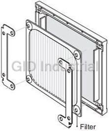
Thrml Mgmt Access Plug and Cord Set 150mm 01505-4-6711
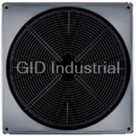
Thrml Mgmt Access Grill Guard 300mm Black Phosphatized Steel Wire 09415-2-4039
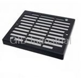
Thrml Mgmt Access Grill Guard 119mm 10016-1-5170
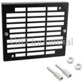
Thrml Mgmt Access Filter Guard Assembly 119mm 10017-1-5170
Thrml Mgmt Access Filter Guard Assembly 119mm 10018-1-5170
Thrml Mgmt Access Filter Fan 10020-1-5170
Request a Quote

The quote request has been received
Close

Facing challenges or have inquiries? Feel free to contact us!
Call Us +1-469-283-2440
What they say about us
FANTASTIC RESOURCE
One of our top priorities is maintaining our business with precision, and we are constantly looking for affiliates that can help us achieve our goal. With the aid of GID Industrial, our obsolete product management has never been more efficient. They have been a great resource to our company, and have quickly become a go-to supplier on our list!
Bucher Emhart Glass
EXCELLENT SERVICE
With our strict fundamentals and high expectations, we were surprised when we came across GID Industrial and their competitive pricing. When we approached them with our issue, they were incredibly confident in being able to provide us with a seamless solution at the best price for us. GID Industrial quickly understood our needs and provided us with excellent service, as well as fully tested product to ensure what we received would be the right fit for our company.
Fuji
HARD TO FIND A BETTER PROVIDER
Our company provides services to aid in the manufacture of technological products, such as semiconductors and flat panel displays, and often searching for distributors of obsolete product we require can waste time and money. Finding GID Industrial proved to be a great asset to our company, with cost effective solutions and superior knowledge on all of their materials, it’d be hard to find a better provider of obsolete or hard to find products.
Applied Materials
CONSISTENTLY DELIVERS QUALITY SOLUTIONS
Over the years, the equipment used in our company becomes discontinued, but they’re still of great use to us and our customers. Once these products are no longer available through the manufacturer, finding a reliable, quick supplier is a necessity, and luckily for us, GID Industrial has provided the most trustworthy, quality solutions to our obsolete component needs.
Nidec Vamco
TERRIFIC RESOURCE
This company has been a terrific help to us (I work for Trican Well Service) in sourcing the Micron Ram Memory we needed for our Siemens computers. Great service! And great pricing! I know when the product is shipping and when it will arrive, all the way through the ordering process.
Trican Well Service
GO TO SOURCE
When I can't find an obsolete part, I first call GID and they'll come up with my parts every time. Great customer service and follow up as well. Scott emails me from time to time to touch base and see if we're having trouble finding something.....which is often with our 25 yr old equipment.
ConAgra Foods