

 Manufacturers
ERNI ELECTRONICS 014818
Description
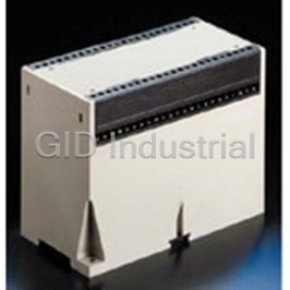
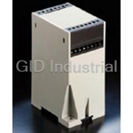
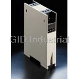
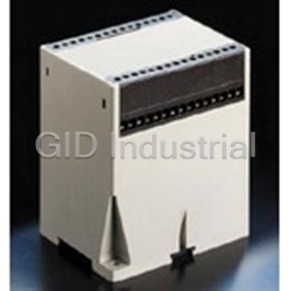
Enclosures LDG-A Cover
014818
Part Number
014818
Price
Request Quote
Manufacturer
ERNI ELECTRONICS
Lead Time
Request Quote
Category
Thermal Management » Misc Products
Specifications
Manufacturer
ERNI Electronics
Manufacturers Part #
014818
Industry Aliases
14818
Sub-Categories
Miscellaneous Tools and Supplies
Factory Pack Quantity
10
Datasheet

Extracted Text
Enclosures LDG-A www.erni.com Catalog E 074485 06/10 Edition 2 www.erni.com Catalog E 074485 06/10 Edition 2 www.erni.com Enclosures LDG-A Table of Contents General information about LDG-A enclosures ................................................................. 2 Technical Data......................................................................................... 3 Temperature Range ..................................................................................... 3 The base for economical and compact packaging of your electronics . . . . . . . . . . . . . . . . . . . . . . . . . . . . . . . . . . . . . . . . . . . . . . . 4 Terminal block design and type overview ..................................................................... 5 Pluggable terminals and blind inserts ....................................................................... 6 Flexibility for customized solutions .......................................................................... 7 Enclosure versions with ventilation slots...................................................................... 8 Enclosure LDG-A 12 .................................................................................... 9 Enclosure LDG-A 14 ................................................................................... 12 Enclosure LDG-A 16 . .................................................................................. 14 Enclosure LDG-A 30 ................................................................................... 16 Enclosure LDG-A 46 ................................................................................... 18 Enclosure LDG-A 70 ................................................................................... 20 Catalog E 074483 06/10 Edition 2 www.erni.com 1 Enclosures LDG-A Types Features LDG-A-12, max. 12 screw clamp terminals • Snap-in design for fast end assembly LDG-A-14, max. 14 screw clamp terminals • Complete assembly of the unit outside of the housing LDG-A-16, max. 16 screw clamp terminals before LDG-A-30, max. 30 screw clamp terminals end assembly LDG-A-46, max. 46 screw clamp terminals • Robust self locking vibration proof terminal block screws LDG-A-70, max. 70 screw clamp terminals • Protection against accidental human contact • Transparent cover for LED indicators • Suitable frame inserts for pluggable standard connectors General • Base parts with and without ventilation slots The LDG-A series of enclosures are fully insulated enclosures. • Base part metallized The screw clamp terminals are protected against accidental • Compact and attractive design contact in accordance with VDE 0100 Part 570, VDE 0160 • Wall and DIN rail mountable Part 100 and VBG 4. Designed for easy installation, these screw terminals can be soldered by wave, allowing the manufacturing of the PCB boards in one step. 2 Catalog E 074485 06/10 Edition 2 www.erni.com Enclosures LDG-A Technical Data Type LDG-A-12 LDG-A-14 LDG-A-16 LDG-A30 LDG-A-46 LDG-A-70 Degree of protection IP20 Air distances ≥ 3 mm ≥ 4 mm Creepage distances ≥ 3.2 mm ≥ 5 mm Voltage rating (IEC 60664) The permissible operating voltages depend on the customer application and on the applicable or specified safety require- ments. Insulation coordination according to IEC 60664-1 has to be regarded for the complete electrical device. Therefore, the maximum creepage and clearance distances of the mated connectors are specified for consideration as a part of the whole current path. In practice, reductions in creepage or clearance distances may occur due to the conductive pattern of the prin- ted board or the wiring used, and have to be taken into account separately. As a result the creepage and clearance distances for the application may be reduced compared to those of the connector. Screw clamp steel, tin plated 2 2 Terminal wire size max. 2.5 mm max. 4 mm current rating max. 16 A max. 20 A tightening torque max. 0.4 Nm material CuSn6 Ms Terminal pin plating 2 µm Ni 2 µm Ni 5 µm Sn 5 µm Sn Temperature range -40° C ... +110° C Base part PC (30% GF), RAL 7032, UL 94 V-1 Terminal block housing, blind plug, cover PC, UL 94 V-2 Frame insert and blind insert PC, UL 94 V-0 Outside dimensions L x B x H 75 x 22.5 x 98.5 mm 75 x 45 x 110 mm 75 x 55 x 110 mm 75 x 99.7 x 110 mm 75 x 150 x 110 mm 75 x 225 x 110 mm 75 x 22.5 x 110 mm Aprovales UL File E 84703 CSA File LR 62504 Temperature Range Inside temperature 95° Enclosure Ambient temperature Typ 23°C 50°C 70°C LDG-A- A A C A B C A B C 12 8 6 3 5 4 2 2,5 2 1 14 12 10 7 7 6 4 4 3 2 16 13 11 9 8 7 5 4 3,5 3 30 19 18 16 12 11 10 7 6 5 46 26 23 20 16 14 12 9 8 7 70 36 33 30 23 21 19 12 10 11 Dissipation in W A = Both side faces not obstructed, free airflow B = One side face blocked by obsruction, 0 mm away C = Both side face blocked by obsruction, 0 mm away Catalog E 074483 06/10 Edition 2 www.erni.com 3 Enclosures LDG-A The base for all applications Fully-insulated enclosures in accordance with machinery and automotive industry standards, with shockproof terminals acc. to VDE 0100 and VBG 4. Base part optionally with or without ventilation slots. Enclosure surface with erosion-structure in attractive design. Easy assembly and disassembly for servicing. Easy connecting technique Generously dimensioned stacking compartment From the connection cable via the terminal block to the Printed circuit boards can be stacked one above the other PC board, the connection could not be more simple. such that complex assemblies can be implemented in compact dimensions. Fast component-mounting and manufacturing times Just snap them on The PC board, with the mounted components and terminal LDG-A enclosures have a snap-on clip for easy snap-on blocks will be wave-soldered, in one work process and assembly for standard DIN rails acc. to DIN 46277 and then completely assembled into the base part in one step. DIN EN 50022. 4 Catalog E 074485 06/10 Edition 2 www.erni.com Enclosures LDG-A Terminal block design and type overview LDG-A 12 Length: 75 mm Width: 22.5 mm Height: 98.5 mm or 110 mm LDG-A 14 Length: 75 mm Width: 45 mm Height: 110 mm LDG-A 16 Length: 75 mm 1 Terminal clamp Width: 55 mm 2 Terminal pin Height: 110 mm 3 Terminal block housing 4 Blind plug LDG-A 14, 16, 30, 46, 70 LDG-A 30 Length: 75 mm Width: 99.7 mm Height: 110 mm LDG-A 46 Length: 75 mm Width: 150 mm Height: 110 mm LDG-A 70 1 Terminal clamp 2 Terminal pin, short Length: 75 mm 2a Terminal pin, long Width: 225 mm 3 Terminal block housing, narrow Height: 110 mm 3a Terminal block housing, wide 4 Blind plug Catalog E 074483 06/10 Edition 2 www.erni.com 5 Enclosures LDG-A Plugable terminals and blind inserts Easy service and device exchange Frame inserts with cut-out for comercially available pluggable terminal connectors Features: • Used as assembly and guide element for the PC board with guides for transverse board and longitudinal board offset by 90°. • Compact design for secure snap-on and safe fixing on the base part. • Screw-on option for the cover. Frame insert with top cutout for separate pin header. For Connection of commercially available screw-plug maximum component space on the longitudinal board. connectors. Ordering information Description Color Part no. Frame insert with top cutout for separate pin header. LDG-A-16 You will have the maximum component space on the Frame insert with PC board. top cutout black 053869 Frame insert with bottom cutout allows the assembly Frame insert with of a transverse board. bottom cutout black 053870 The blind insert provides for the full covering of the base Blind insert black 053871 part. Individual customized cutouts achieved by mechanical LDG-A-30 machining or special tool inserts are easy to be realized. Frame insert with top cutout black 034769 Technical data Frame insert with Material of plastic parts: PC bottom cutout black 053164 UL 94 V-0 Blind insert black 053074 Color: black LDG-A-46 special colors upon request Frame insert with Temperature range: -40°C up to +110°C bottom insert black 054248 Blind insert black 054249 LDG-A-70 Blind insert black 054730 6 Catalog E 074485 06/10 Edition 2 www.erni.com Enclosures LDG-A Flexibility for customized solutions Various colors, e. g. company color for base part, cover or terminal block possible Cover in grey, black or Customized cutouts and holes transparent for display functions in covers and blind inserts Catalog E 074483 06/10 Edition 2 www.erni.com 7 Enclosures LDG-A Versions with ventilation slots Effective heat dissipation for electronic subassemblies with increased heating Base part with ventilation slots - availiable for enclosure versions LDG-A-12, LDG-A-16, LDG-A-30, LDG-A-46, LDG-A-70 - slot dimension: 42 x 3 mm - additional data upon request Ordering information Description Color Part no. Base part with ventilation slots 114932 LDG-A-12 light grey 024870 LDG-A-16 light grey 434098 LDG-A-30 light grey 024080 LDG-A-46 light grey 424328 LDG-A-70 light grey 8 Catalog E 074485 06/10 Edition 2 www.erni.com Enclosures LDG-A LDG-A 12 • For max. 12 screw clamp terminals, 6 on each side • Partial loaded terminal blocks with blind plugs • PCB board arrangement see drawing Length: 75 mm Width: 22.5 mm Height: 98.5 mm or 110 mm Ordering information Description Type Color Part Number Base part 110 mm w/o ventilation slot light grey 024082 Base part 110 mm with ventilation slot light grey 114932 Base part 98,5 mm w/o ventilation slot light grey 414470 Cover transparent 414462 Cover light grey 414463 Terminal block housing right black 414453 Terminal block housing left black 414455 Terminal pin right, long 224082 Terminal pin right, medium 224079 Terminal pin right, short 224078 Terminal pin left, long 224081 Terminal pin left, medium 224077 Terminal pin left, short 224080 Clamp, not assembled 414469 Terminal block, fully loaded right black 043853 Terminal block, fully loaded left black 043860 Blind plug black 414466 Catalog E 074483 06/10 Edition 2 www.erni.com 9 15 ° 56 ° 15 ° Enclosures LDG-A LDG-A 12 Dimensions: low height version 22,5 20,1 1,2 Deckel Cover 5,6 25 5,6 Querplatine Klemmengehäuse, rechts 3,2 Crosswise circuit board 2,55 23 Terminal housing, right Klemmengehäuse, links Terminal housing, left Klemme Terminal Printklemmstift, rechts Schraubenloch für Blechschraube PCB terminal pin, right Hole for tapping scr ew lang, mittel, kurz long, middle, short ISO 1481-ST 2,2x6,5 Längsplatine Blindstopfen / Blind plug Printklemmstift, links Lengthwise circuit board (anstelle Klemme und Print-Klemmstift) PCB terminal pin, left (in place of terminal and terminal pin) lang, mittel, kurz long, middle, short Gehäuse-Unterteil 5,5 Housing base Rastschieber 8 Sliding catch 35,5 13,5 17,4 19,8 72 1 75 all dimensions in mm Recommended PCB dimensions Längsplatine / Lengthwise circuit board 61 54,61 / Crosswise circuit board Querplatine 52,07 48 36,83 Belegungsgrenze ist abhängig von der Einbaulage der Querplatine 29,21 +0,1 22 length available for components 17,4 1,2 22,5 depends on the location of the crosswise circuit board 47 24,5 1) Höhe ist abhängig von der Einbaulage der Querplatine 5,5 13,25 1) height depends on location of 8,5 70 the crosswise circuit board 71,5 -0,3 17,25 Belegungsgrenze für Bauelemente mounting limit for components all dimensions in mm 10 Catalog E 074485 06/10 Edition 2 www.erni.com 88,5 5,08 34,29 5,08 33,7 5,08 41,5 17,78 5,08 15,2 92 72 5x3,1= 15,5 55,5 3,1 5 1,8 4,5 10,16 13,97 1,5 4,445 19 1,7 2,8 11,7 14,1 14,5 54 89,2 +0,1 2,6 1 -0,1 17 98,5 17,5 1,6 -0,3 1) max. 14,1 15 ° 56 ° 15 ° Enclosures LDG-A LDG-A 12 Dimensions: standard height version 22,5 20,1 Deckel 1,2 Cover 5,6 25 5,6 Querplatine Klemmengehäuse, rechts Crosswise circuit board 3,2 2,55 23 Terminal housing, right Klemmengehäuse, links Klemme Terminal housing, left Terminal Printklemmstift, rechts Schraubenloch für Blechschraube PCB terminal pin, right Hole for tapping scr ew lang, mittel, kurz long, middle, short ISO 1481-ST 2,2x6,5 Blindstopfen / Blind plug Printklemmstift, links (anstelle Klemme und Print-Klemmstift) PCB terminal pin, left (in place of terminal and terminal pin) Längsplatine lang, mittel, kurz long, middle, short Lengthwise circuit board Gehäuse-Unterteil Housing base 5,5 8 Rastschieber Sliding catch 35,5 13,5 17,4 19,8 72 1 75 all dimensions in mm Recommended PCB dimensions Längsplatine / Lengthwise circuit board 61 54,61 52,07 Querplatine / Crosswise circuit board 48 36,83 Belegungsgrenze ist abhängig von der Einbaulage der Querplatine 29,21 +0,1 17,4 length available for components 1,2 22,5 depends on the location of the crosswise circuit board 22 47 24,5 1) Höhe ist abhängig von der 5,5 13,25 Einbaulage der Querplatine 8,5 1) 70 height depends on location of the crosswise circuit board 71,5 -0,3 17,25 Belegungsgrenze für Bauelemente all dimensions in mm mounting limit for components Catalog E 074483 06/10 Edition 2 www.erni.com 11 100 5,08 34,29 5,08 33,7 5,08 53 5,08 17,78 15,2 103,5 83,5 5x3,1= 15,5 67 3,1 5 1,8 4,5 10,16 13,97 1,5 4,445 19 1,7 2,8 11,7 65,5 14,1 14,5 100,7 +0,1 2,6 1 -0,1 17 1,6 17,5 -0,3 1) max. 14,1 110 Enclosures LDG-A LDG-A 14 • For max. 14 screw clamp terminals , 7 on each side • Partial loaded terminal blocks with blind plugs • PCB board arrangement see drawing Length: 75 mm Width: 45 mm Height: 110 mm Ordering information Description Type Color Part Number Base part w/o ventilation slots light grey 423280 Cover light grey 423273 Cover transparent 423272 Cover black 423274 Terminal block housing narrow black 423275 Terminal block housing wide black 423277 Terminal pin short 224076 Terminal pin long 224074 Clamp, not assembled 154562 Terminal block, fully loaded narrow black 914810 Terminal block, fully loaded wide black 914820 Blind plug black 103006 12 Catalog E 074485 06/10 Edition 2 www.erni.com 15 ° Enclosures LDG-A LDG-A 14 Dimensions 45 Gehäuse-Deckel 42,2 75 Cover 50,4 6x5,9= 35,4 Klemmengehäuse (breit) 45,8 5,9 Terminal housing (wide) Klemmengehäuse (schmal) Terminal housing (narr ow) Querplatine Crosswise circuit board Print-Klemmstift (lang) Print-Klemmstift (kurz) PCB terminal pin (long) 1,8 PCB terminal pin (short) 3 Klemme Terminal 23,6 Längsplatine Lengthwise circuit board Blindstopfen / Blind plug (anstelle Klemme und Print-Klemmstift) (in place of terminal and terminal pin) Gehäuse-Unterteil Housing base Rastschieber 5,5 8 Sliding catch 35,5 13,5 Schraubenloch für Blechschraube 72 Hole for tapping scr ew 39,8 ISO 1481-ST 2,2x6,5 12 1,8 all dimensions in mm Recommended PCB dimensions Längsplatine / Lengthwise circuit board Querplatine / Crosswise circuit board bei breitem Klemmengehäuse 4 30 for wide terminal housing bei schmalem Klemmengehäuse 18 16 for narrow terminal housing 41,7 -0,3 45 1,6 0,1 6x5,9= 35,4 23,6 0,1 49,6 8,5 13,5 40,2 Belegungsgrenze für Bauelemente wie gezeichnet bzw . spiegelbildlich 1) Höhe ist abhängig von der mounting limit for components Einbaulage der Querplatine as drawn or mirror image 1) height depends on location of Achtung: Im Eckenbereich verringerte Einbauhöhen the crosswise circuit board Note: reduced space for components in the cor ner area all dimensions in mm Catalog E 074483 06/10 Edition 2 www.erni.com 13 1) max. 99,5 1) min. 85,5 81,6 75,8 103,3 68,8 100,5 86,5 3x3,3= 9,9 69,8 3,3 5 1,8 Mitte Gehäuse / center of housing 1,7 40,2 5,1 +0,1 1,7 1,6 12,2 +0,1 21,5 2,6 15 18,8 17 1,6 42,2 -0,3 1) 76,3 max. 12,2 82,1 2,8 110 Enclosures LDG-A LDG-A 16 • For max. 16 screw clamp terminals, 8 on each side • Partial loaded terminal blocks with blind plugs • PCB board arrangement see drawing • Special frames for pluggable standard connectors availa- ble Length: 75 mm Width: 55 mm Height: 110 mm Ordering information Description Type Color Part Number 414124 Base part w/o ventilation slots light grey 024870 Base part with ventilation slots light grey 014415 Cover light grey 014416 Cover transparent 014417 Cover black 103031 Terminal block housing narrow black 103033 Terminal block housing narrow blue 103032 Terminal block housing wide black 103034 Terminal block housing wide blue 224076 Terminal pin short 224074 Terminal pin long 154562 Clamp, not assembled 914830 Terminal block, fully loaded narrow black 914840 Terminal block, fully loaded wide black 103006 Blind plug black Frame insert for pluggable 053869 connectors Top cutout black Frame insert for pluggable 053870 connectors Bottom cutout black 053871 Blind insert black 14 Catalog E 074485 06/10 Edition 2 www.erni.com 15 ° R6,5 15 ° 15 ° 15 ° Enclosures LDG-A LDG-A 16 Dimensions Gehäuse-Deckel 55 75 Cover 52 50,4 Klemmengehäuse (breit) 7x6 42 45,8 = Klemmengehäuse (schmal) Terminal housing (wide) 6 Terminal housing (narrow) Querplatine Crosswise circuit board Print-Klemmstift (lang) Print-Klemmstift (kurz) PCB terminal pin (long) 2,5 1,8 PCB terminal pin (short) 3 Klemme Terminal 30 Längsplatine Lengthwise circuit boar d Blindstopfen / Blind plug (anstelle Klemme und Print-Klemmstift) (in place of terminal and terminal pin) Gehäuse-Unterteil Housing base Rastschieber 5,5 8 Sliding catch 13,8 35,5 13,5 Schraubenloch für Blechschraube 72 Hole for tapping screw 39,8 ISO 1481-ST 2,2x6,5 12 1,8 60 62,5 all dimensions in mm Recommended PCB dimensions / Lengthwise circuit board Querplatine / Crosswise circuit board Längsplatine bei breitem Klemmengehäuse 4 30 for wide terminal housing bei schmalem Klemmengehäuse 18 16 for narrow terminal housing 45 51,5 -0,3 1,6 0,1 7x6 42 = 30 0,1 49,6 12,6 8,5 14 13,6 50 Belegungsgrenze für Bauelemente wie gezeichnet bzw . spiegelbildlich mounting limit for components 1) as drawn or mirror image Höhe ist abhängig von der Einbaulage der Querplatine 1) height depends on location of Achtung: Im Eckenbereich verringerte Einbauhöhen the crosswise circuit board Note: reduced space for components in the cor ner area all dimensions in mm Catalog E 074483 06/10 Edition 2 www.erni.com 15 15 ° 1) max. 99,7 1) min. 85,4 81,8 76 69 43,5 3,3 103,5 100,7 86,4 4x2,5= 10 37,5 70 2,5 4,5 5 1,8 Mitte Gehäuse / center of housing 5,3 50 1,7 12,5 15,3 19,1 17 +0,1 1,7 1,6 3,3 +0,1 21,5 2,6 43,5 3,7 2,8 43,5 76,5 82,3 110 1,6 52 -0,3 1) max. 12,5 Enclosures LDG-A LDG-A 30 • For max. 30 screw clamp terminals, 15 on each side • Partial loaded terminal blocks with blind plugs • PCB board arrangement see drawing Usage of standard connectors • Special frames for pluggable standard connectors available • Pitch of 5.08 mm allows connection of 17 wires on each side Length: 75 mm Width: 99.7 mm Height: 110 mm Ordering information Description Type Color Part Number Base part w/o ventilation slots light grey 414165 Base part with ventilation slots light grey 434098 Cover light grey 413962 Cover transparent 413963 Cover black 413964 Terminal block housing narrow black 413966 Terminal block housing narrow blue 413965 Terminal block housing wide black 413968 Terminal block housing wide blue 413967 Terminal pin short 224076 Terminal pin long 224074 Clamp, not assemnbled 154562 Terminal block, fully loaded narrow black 914850 Terminal block, fully loaded wide black 914860 Blind plug black 103006 Frame insert for pluggable connectors Top cutout black 034769 Frame insert for pluggable connectors Bottom cutout black 053164 Blind insert black 053074 16 Catalog E 074485 06/10 Edition 2 www.erni.com R6,5 15 ° 15 ° 15 ° 15 ° Enclosures LDG-A LDG-A 30 Dimensions Gehäuse-Deckel 75 99,7 Cover 50,4 96,7 Klemmengehäuse (breit) 45,8 14x6= 84 Klemmengehäuse (schmal) Terminal housing (wide) 6 Terminal housing (narrow) Querplatine Crosswise circuit board Print-Klemmstift (lang) Print-Klemmstift (kurz) PCB terminal pin (long) 72 PCB terminal pin (short) 1,8 Klemme 3 Terminal Längsplatine Lengthwise circuit boar d Blindstopfen / Blind plug (anstelle Klemme und Print-Klemmstift) (in place of terminal and terminal pin) Gehäuse-Unterteil Housing base Rastschieber 5,5 8 12,4 Sliding catch 3 35,5 13,5 5,2 auf Wunsch mit Lüftungsschlitzen with ventilation holes on request 72 39,8 Schraubenloch für Blechschraube 12 Hole for tapping screw ISO 1481-ST 2,2x6,5 1,8 60 all dimensions in mm 62,5 Recommended PCB dimensions Längsplatine / Lengthwise circuit board Querplatine / Crosswise circuit board bei breitem Klemmengehäuse 45 96.2 -0.3 4 for wide terminal housing 30 18 bei schmalem Klemmengehäuse 14x6= 84 ±0.1 16 for narrow terminal housing ±0.1 72 1.6 49.6 12,6 12,6 8.5 13,6 94.7 Belegungsgrenze für Bauelemente wie gezeichnet bzw . spiegelbildlich 1) mounting limit for components Höhe ist abhängig von der as drawn or mirror image Einbaulage der Querplatine Achtung: Im Eckenbereich verringerte Einbauhöhen 1) height depends on location of all dimensions in mm the crosswise circuit board Note: reduced space for components in the cor ner area Catalog E 074483 06/10 Edition 2 www.erni.com 17 15 ° 1) max. 99,7 1) min. 85,7 81,8 76 69 43,5 3,3 103,5 100,7 86,7 3x3,3= 9,9 70 3,3 85 5 4,5 1,8 Mitte Gehäuse / center of housing 1,7 94,7 5,1 12,2 15 18,8 17 +0,1 1,7 1,6 +0,1 3,3 2,6 21,7 42 43,5 3,7 43,5 76,5 2,8 82,3 110 1.6 96.7 -0.3 1) max. 12.2 Enclosures LDG-A LDG-A 46 • For max. 46 screw clamp terminals, 23 on each side • Partial loaded terminal blocks with blind plugs • PCB board arrangement see drawing Usage of standard connectors • Special frames for pluggable standard connectors available • Pitch of 5.08 mm allows connection of 26 wires on each side Length: 75 mm Width: 150 mm Height: 110 mm Ordering information Description Type Color Part Number Base part w/o ventilation slots light grey 024078 Base part with ventilation slots light grey 024080 Cover light grey 014818 Cover transparent 014819 Cover black 014820 Terminal block housing narrow black 014649 Terminal block housing wide black 014790 Terminal pin short black 224076 Terminal pin long black 224074 Clamp, not assemnbled 154562 Terminal block, fully loaded narrow black 914890 Terminal block, fully loaded wide black 914900 Blind plug black 103006 Frame insert for pluggable connectors Bottom cutout black 054248 Blind insert black 054249 18 Catalog E 074485 06/10 Edition 2 www.erni.com R7,5 15 ° 15 ° 15 ° 15 ° Enclosures LDG-A LDG-A 46 Dimensions Gehäuse-Deckel Sonderschraube 75 149 Cover Special screw 50,4 144 45,8 22x6= 132 Klemmengehäuse (breit) Klemmengehäuse (schmal) 39,8 Terminal housing (wide) 6 Terminal housing (narrow) Querplatine Crosswise circuit board Print-Klemmstift (lang) Print-Klemmstift (kurz) PCB terminal pin (long) 120 PCB terminal pin (short) Klemme 1,8 Terminal 3 Längsplatine Lengthwise circuit boar d Blindstopfen / Blind plug (anstelle Klemme und Print-Klemmstift) (in place of terminal and terminal pin) Gehäuse-Unterteil Housing base 4,9 Rastschieber Sliding catch 3 10 12,4 35,5 12,5 5,2 70 Schraubenloch für Blechschraube 39,8 Hole for tapping screw 12 ISO 1481-ST 2,2x6,5 1,8 auf Wunsch mit Lüftungsschlitzen with ventilation holes on request 60 62,5 all dimensions in mm Recommended PCB dimensions Querplatine / Crosswise circuit board Längsplatine / Lengthwise circuit board 39 bei breitem Klemmengehäuse for wide terminal housing 143.5 4 29 -0.3 bei schmalem Klemmengehäuse 18 15 ±0.1 for narrow terminal housing 22x6= 132 ±0.1 120 1.6 49.6 12,6 12,6 10.5 142 Belegungsgrenze für Bauelemente wie gezeichnet, bzw . spiegelbildlich 1) Höhe ist abhängig von der mounting limit for components Einbaulage der Querplatine as drawn or mirror image 1) Achtung: Im Eckenbereich verringerte Einbauhöhen height depends on location of all dimensions in mm the crosswise circuit board Note: reduced space for components in the cor ner area Catalog E 074483 06/10 Edition 2 www.erni.com 19 15 ° 1) max. 97.2 1) min. 84.5 80.6 74.8 67.8 43,3 2,2 102,3 99,5 85,5 2x3,3= 6,6 134,3 68,8 3,3 4,5 5 1,8 142 12,3 2,5 15 18,8 17 42 / center of housing Mitte Gehäuse +0.1 2,2 Ø1.6 2,5 +0.1 Ø2.6 20,6 43,3 2,6 43,3 75,3 4,6 81,1 110 1.6 1) 144 -0,3 max. 12.2 Enclosures LDG-A LDG-A 70 • For max. 70 screw clamp terminals, 35 on each side, clamp pitch 6 mm • Partial loaded terminal blocks with blind plugs • PCB board arrangement see drawing Usage of standard connectors • Special frames for pluggable standard connectors available • Pitch of 5.08 mm allows connection of 41 wires on each side Length: 75 mm Width: 225 mm Height: 110 mm Ordering information Description Type Color Part Number 424327 Base part w/o ventilation slots light grey 424328 Base part with ventilation slots light grey 424243 Cover light grey 424244 Cover transparent 424245 Cover black 424240 Terminal block housing narrow black 424239 Terminal block housing narrow blue 424242 Terminal block housing wide black 424241 Terminal block housing wide blue 224076 Terminal pin short 224074 Terminal pin long 154562 Clamp, not assemnbled 914870 Terminal block, fully loaded narrow black 914880 Terminal block, fully loaded wide black 103006 Blind plug black 054730 Blind insert black 20 Catalog E 074485 06/10 Edition 2 www.erni.com R7,5 15 ° 15 ° 15 ° 15 ° Enclosures LDG-A LDG-A 70 Dimensions 224,7 Gehäuse-Deckel Sonderschraube 75 Cover 219,7 Special screw 50,4 34x6= 204 45,8 Klemmengehäuse (breit) 6 Klemmengehäuse (schmal) Terminal housing (wide) 39,8 Terminal housing (narrow) Querplatine Crosswise circuit board Print-Klemmstift (lang) Print-Klemmstift (kurz) PCB terminal pin (long) 192 PCB terminal pin (short) Klemme 1,8 Terminal 3 Längsplatine Lengthwise circuit boar d Blindstopfen / Blind plug (anstelle Klemme und Print-Klemmstift) (in place of terminal and terminal pin) Gehäuse-Unterteil Housing base Rastschieber 4,9 3 10 Sliding catch 35,5 12,5 12,4 Schraubenloch für Blechschraube 5,2 Hole for tapping screw 70 ISO 1481-ST 2,2x6,5 39,8 12 auf Wunsch mit Lüftungsschlitzen 1,8 with ventilation holes on request 60 62,5 all dimensions in mm Recommended PCB dimensions Querplatine / Crosswise circuit board / Lengthwise circuit board Längsplatine bei breitem Klemmengehäuse for wide terminal housing 219,2 39 -0,3 4 29 bei schmalem Klemmengehäuse 18 15 34x6= 204 0,1 for narrow terminal housing 192 0,1 1.6 49.6 12,6 10,5 10,5 12,6 75 217,7 1) Belegungsgrenze für Bauelemente Höhe ist abhängig von der wie gezeichnet, bzw . spiegelbildlich Einbaulage der Querplatine Achtung: Im Eckenbereich verringerte Einbauhöhen mounting limit for components 1) Note: reduced space for components in the corner area height depends on location of as drawn or mirror image all dimensions in mm the crosswise circuit board Catalog E 074483 06/10 Edition 2 www.erni.com 21 15 ° 1) max. 97.2 1) min. 84.5 80.6 74.8 102,3 99,5 67.8 85,5 43,3 2x3,3= 6,6 2,2 210 68,8 3,3 5 4,5 1,8 12,3 2,5 75 15 18,8 217,7 17 42 Mitte Gehäuse / center of housing +0.1 2,2 Ø1.6 +0.1 2,5 Ø2.6 20,6 43,3 1.6 1) 219,7 12.2 -0,3 max. 2,6 43,3 75,3 4,6 81,1 110 ERNI Electronics GmbH & Co. KG Europe South America Africa Japan Seestrasse 9 73099 Adelberg/Germany Tel +49 7166 50-0 Fax +49 7166 50-282 info@erni.de ERNI Electronics, Inc. North America Canada Mexico 2201 Westwood Ave Richmond, VA 23230/USA Tel +1 804 228-4100 Fax +1 804 228-4099 info@erni.us ERNI Asia Holding Pte Ltd. Asia Australia New Zealand Blk 4008 Ang Mo Kio Avenue 10 #04-01/02 Techplace I Singapore 569625 Tel +65 6 555 5885 Fax +65 6 555 5995 info@erni-asia.com www.erni.com © ERNI Electronics GmbH & Co. KG 2010 • Printed in Germany. A policy of continuous improvement is followed and the right to alter any published data without notice is reser- ® ® ® ® ® ® ® ® ® ved. ERNI , MicroStac , MicroSpeed , MiniBridge , MaxiBridge , ERmet , ERmet ZD , ERbic and ERNIPRESS are trademarks (registered or applied for in various countries) of ERNI Electronics GmbH & Co. KG. Catalog E 074485 06/10 Edition 2 www.erni.com
Frequently asked questions
How does Electronics Finder differ from its competitors?

Is there a warranty for the 014818?
Which carrier will Electronics Finder use to ship my parts?
Can I buy parts from Electronics Finder if I am outside the USA?
Which payment methods does Electronics Finder accept?
Why buy from GID?

Quality
We are industry veterans who take pride in our work

Protection
Avoid the dangers of risky trading in the gray market

Access
Our network of suppliers is ready and at your disposal

Savings
Maintain legacy systems to prevent costly downtime

Speed
Time is of the essence, and we are respectful of yours
Related Products
Enclosures LDG-A, Cover 014415
Enclosures LDG-A Cover 014417
Enclosures LDG-A Cover 014820
Base Part of Enclosure 110mm without Ventilation Slots, Light Gray 024082
Base Part of Enclosure with Ventilation Slots, Light Gray 024870
Enclosures LDG-A Framer Insert 034769
Request a Quote

The quote request has been received
Close

Facing challenges or have inquiries? Feel free to contact us!
Call Us +1-469-283-2440
What they say about us
FANTASTIC RESOURCE
One of our top priorities is maintaining our business with precision, and we are constantly looking for affiliates that can help us achieve our goal. With the aid of GID Industrial, our obsolete product management has never been more efficient. They have been a great resource to our company, and have quickly become a go-to supplier on our list!
Bucher Emhart Glass
EXCELLENT SERVICE
With our strict fundamentals and high expectations, we were surprised when we came across GID Industrial and their competitive pricing. When we approached them with our issue, they were incredibly confident in being able to provide us with a seamless solution at the best price for us. GID Industrial quickly understood our needs and provided us with excellent service, as well as fully tested product to ensure what we received would be the right fit for our company.
Fuji
HARD TO FIND A BETTER PROVIDER
Our company provides services to aid in the manufacture of technological products, such as semiconductors and flat panel displays, and often searching for distributors of obsolete product we require can waste time and money. Finding GID Industrial proved to be a great asset to our company, with cost effective solutions and superior knowledge on all of their materials, it’d be hard to find a better provider of obsolete or hard to find products.
Applied Materials
CONSISTENTLY DELIVERS QUALITY SOLUTIONS
Over the years, the equipment used in our company becomes discontinued, but they’re still of great use to us and our customers. Once these products are no longer available through the manufacturer, finding a reliable, quick supplier is a necessity, and luckily for us, GID Industrial has provided the most trustworthy, quality solutions to our obsolete component needs.
Nidec Vamco
TERRIFIC RESOURCE
This company has been a terrific help to us (I work for Trican Well Service) in sourcing the Micron Ram Memory we needed for our Siemens computers. Great service! And great pricing! I know when the product is shipping and when it will arrive, all the way through the ordering process.
Trican Well Service
GO TO SOURCE
When I can't find an obsolete part, I first call GID and they'll come up with my parts every time. Great customer service and follow up as well. Scott emails me from time to time to touch base and see if we're having trouble finding something.....which is often with our 25 yr old equipment.
ConAgra Foods