

 Manufacturers
ERNI ELECTRONICS 203002

Description
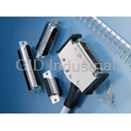
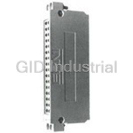
Cable Housings KSG 173 203 253193 For Connectors to DIN 41 612 And VG 95 324
203002
Part Number
203002
Price
Request Quote
Manufacturer
ERNI ELECTRONICS
Lead Time
Request Quote
Category
Connectors » Connector Accessories
Specifications
Manufacturer
ERNI Electronics
Manufacturers Part #
203002
Industry Aliases
203002
Sub-Category
Connector Accessories
Factory Pack Quantity
1
Datasheet

Extracted Text
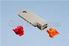
Mateable transfer wiring-system for connectors to DIN 41 612 and VG 95 324 1 ERNI Elektroapparate GmbH D-73099 Adelberg -a- ++49-7166-500 � 7 27 759 Telefax: ++49-7166-50 282 1.12 Table of contents Cable housings for connectors to DIN 41 612 and VG 95 324 General, Patterns, Packing Dimensions Technical data, Coding system Cable housings KSG 173 for connectors type B, C, D, E, H11, H15, Q, R KSG 203 for female connectors type F KSG 253 for female ribbon-cable (IDC)-connectors type C Individual parts, Ordering information Guide elements for front panel connection Guide elements for mounting through wiring field andlor backplanes Guide elements for mounting on rear side of 19" racks Guide frames for fitting within the wiring plane Application examples KSG 173 Circuit board drilling pattern for male and female connectors to DIN 41 612 with angled connecting pins Cable housings KSG 193 for male and female connectors types BK and CK (half-length VG connectors) Dimensions, Ordering information Guide elements for front mounting connections Guide elements for mounting on wiring planes Guide elements for mounting within the wiring planes Circuit board drilling pattern for male and female connectors to VG 95 324 (half-length VG connectors) with angled connecting pins Wiring elements and plug-on distribution connectors Electrical and mechanical characteristics, General Dimensions, Ordering information Index of Part-Nos. Cable housings KSG 173, 203,253,193 for connectors DIN 41 612 and VG 95 324 General: All housings in this family offer the following advantages This cable housing family meets the demand for a fully-in- sulated compact housing suitable for holding either the eA strong, fully insulated housing; male or female half of connectors to DIN 41 612. Exclusion of any mechanical stress on the multi-pin con- The mechanical protection provided by the cable housings nectors during insertion, operation and withdrawal; makes these PCB-related connectors suitable for all kind Lifting screws (which can be turned successively) maki of electrical interfaces. They can be used as board-to- it easy to overcome insertion and withdrawal forces; wire connectors, as coding or test plugs or as plug-in jum- Suitable guide elements to facilitate mounting on thi per connections. front panels or wiring ends of PCB modules; Suitable guide elements assist in matching the two con- Suitable for providing signal or current interconnection! nector halves and also offer coding possibilities. between (W-) racks; Three alternative cable outlet positions; These universal cable housings have been develo- a Reliable strain-relief; ped in close cooperation with leading manufactu- rers of electronic equipment. Retrofitting of coding devices possible; Attractive design. Patterns: KSG 193 KSG 173 for male and female connectors types BK and CK for male or female connectors types B, C, D, H 11, Q, R, housing width 15.24 mm (.V) (3T) housing width 15.24 mm (.6) (3T) Female connectors type H 15 Packing: housing width 15.24 mm (.6) (3T) Cable housings for male and female connectors type E as component sets packed in bags - without guide ele- housing width 20.32 mm (.V) (4T) ments Guide elements KSG 203 for female connectors type F as component sets packed in bags including fastening ele- ments housing width 15.24 mm (.6) (3T) KSG 253 Coding for female ribbon-cable (IDC)-connectors type C as component sets packed in bags including fastening ele- ments housing width 15.24 mm (.V) (3T) 3 Dimensions Cable housing KSG 173 for male and female connectors types B, C, D, H1 1, Q, R An adaptor element is necessary for fitting types B and Q. Cable housing KSG 173 for male and female connectors type E Cable crtfy 15x20 mm Gable housings KSG 173 for female connectors type H15 L-+ Cable entry 16x20 mm Cable housings KSG 203 for female connectors type F Cable enliy 11x15 mm = Dimensions Cable housings KSG 253 for female ribbon-cable (IDC) - connectors type C Cable entries at rear and on both sides Cable entry at rear .-,-&# l f* 3 Dimensions Cable housings KSG 253 to carry small electronic circuits LEDs can be fitted at the rear of the cable housing for the visual indication of fault signals or switch positions. IÑ Female connector types C or D Male connector type R Cover plates for fitting diodes KSG 173 (4Tl KSG 253 KSG 173 (3T) KSG 203 Technical data, coding system Cable housings KSG 173, 203, 253,193 for connectors to DIN 41 612 and VG 95 324 Technical data Mouldina material Polycarbonate 30 % GFR 1 Application class 1 EKD DIN 40 040 1 1 Temperature range 1 -65OC to +l 25OC 1 1 Inflammability 1 UL 94 V-1 1 1 Metal parts 1 Steel, surface treated 1 Coding system a Packing Part-No. As comuonent set uacked in a ban: <, 2 coding bushes positive 033 004 2 coding bushes negative and fastening elements 8 Individual parts, ordering details Cable housings KSG 173,203,253 for male and female connectors to DIN 41 612 Individual parts Fillister headscrew M 2.5 x ... DIN 84 2 3 Guide element 4 Blind plug 5 Cable sleeve Fillister head screw M 2.5~ ... DIN 84 6 7 Strain relief 8 Cable guide An adaptor element is necessary for fitting types B and 0. Order details Number of For For Part-No, Cable housing Part-No. 1 connectortype 1 1 cab'e housing 1 cable outlets 1 connectortype 1 1 Outlets at 1 C Insulation 1 KSG 173 1 B,C,D,HII,O,R 173001 KSG 253 253001 sides Connectors KSG 173 2 B,C,D,HII,O,R 173002 C Insulation Displacement 253 002 1 E 173051 KSG 253 KSG 173 at rear Connectors KSG 173 2 E 173052 for KSG 173 1 H15 414886 1 KSG 1 cover plate 1 KSG 173 1 2 1 H15 1 414888 1 1 KSG 203 1 1 1 F 1 203001 1 Cover plate for KSG 173 (3T) Cover plate for KSG 173 (4T) Cover plate for KSG 253 Cable housings with 3 cable outlets on request Adaptor for fitting male or female connectors type B and or Q into KSG 173 Special patterns for particular requirements on request. 9 Guide elements Guide elements for front panel connection with connector types B, C, D, E, F, H 11, H 15, Q, R Explanation - Installation possibilities This interface system gives users the opportunity of provi- ding mateable connections on the front-panels. The guide Pos. 1 Guide elements fitted as a card-edge grip for moun- elements can either be fitted as pull grips or be mounted on ting a male connector resp. inverted female connec- metal front panels. tor (the female connector resp. inverted male con- nector being in the cable housing). Fitting mateable connectors to the front of PCB modules makes it possible to seperate the internal and external wi- Pos. 2 Guide elements fitted as a card-edge grip for the ring and to provide mateable connections between diffe- mounting of a female connector with angled solder rent modules, cabinets or other peripheral equipment. pins (the male half being in the cable housing). This front-side interface system makes it possible to trans- Pos. 3 As Pos. 1 and 2 but for mounting on a front panel. mit sensitive signals without interferences. For the panel cutout see page 11. For PCB-drillings please see page 19 -,,Front mountings". Pos. 4 The guide elements are also suitable for cable hou- sing KSG 253 (the female half being in the cable housing). Order details, mounting cutouts Order details for guide elements (sets) Type Application Part No. Pos. Guide element for B, C, D Male connector Card edge grip 043 518 1 Female connector 0, R, F, H11, H15 E Card edge grip 043 549 1 Male connector Card edge grip 043 519 Female connector B, C, D, H 11 2 Card edge grip 043 550 E 2 Female connector B, C, D Male connector Front panel 043 520 3 Female connector Front panel 043 575 F,H11,H15 3 Male connector E Front panel 043 551 Male connector 3 Front panel 043 523 Female connector B, C, D, H11 3 E Front panel 043 552 Female connector 3 Card edge grip 043 518 Male connector C 4 C Front panel 043 520 4 Male connector Mounting cutout for guide element 043 551 for guide element 043 520 043 552 043 523 043 575 17 l1-----� 21 11 Q, R Guide elements for mounting through wiring fields with connector types B, C, D, E, F, H 11, H 15, Q, R In a similar way to front-mounted connectors, this interface Explanation - Installation possibilities System also provides for making mateable interC0nne~- pas, 1 The guide elements are fitted to the motherboard tions directly from the wiring field to a printed circuit board. support. Alternatively, by fitting suitable spacer The guide elements are mounted on the rails of a subrack washers (included in the set), the guide elements can be fitted directly to a subrack. and serve to locate the PC0 in the rack. Pos. 2 For power connections, the female half is mounted in the cable housing and the male half and PC0 in the subrack to provide protection against accidental contact. Pos. 3 Similar to the front-panel mounting, it is also possi- ble to fit female connectors with right-angled termi- nations or reversed female connectors on the prin- ted circuit board (male connector in the cable hou- sing). Pos. 4The guide elements are also suitable for cable hou- sings KSG 253 (female connector in the cable hou- sing). Order details, mounting cutouts Order details for guide elements [sets) Pos. Guide element for Type Part No. Male connector 1 1 Female connector 1 1 1 1 Male connector 1 F, H11, H15, 1 043553 1 Mounting cutout for guide element 043 554 for guide element 043 553 Possibility of mounting the Possibility of mounting the guide elements either in guide elements either in he row 104,14 (hole dia, 2,6 mm hi row 104.14 (hole dia. 2.6 mm) 0 in hi row 122.5. M 2.5 thread or in hole row 122,5. M 2.5 mead / Guide elements for mounting on mother boards or on printed circuit boards with connector types B, C, D, E, H 11, Q, R The interfacing technique shown in Pos. 1 is particularly Explanation - Installation possibilities suitable for cases and cabinets fitted with pivoting wiring Pos. 1 The guide elements for the female half are mounted frames. on the wiring rails, adjacent to subracks or on a prin- The guide elements are mounted adjacent to or on the ted circuit board. subracks. Pos.2 The guide elements for the male half are mounted A particular advantage of this interface system is the wide on the wiring rails adjacent to the subracks or on a variety of wiring possibilities it offers. Depending on the printed circuit board. method of connection used (wire wrapping, clip to clip, sol- Pos.3 The guide elements are mounted in the interior of der, fast-on or piggy-back) a suitable female connector or the subrack, reversed male connector is mounted on the interfacing field Pos. 4 The guide elements are also suitable for cable hou- so that the interfacing field and the wiring matrix sings type KSG 253 (here the female half is mounted have similar connectors. The male half or reversed female in the cable housing). half is carried in the cable housing. Where circuit boards are used in the wiring field as shown in Pos. 2, on which male half connectors with straight pins are fitted, the guide elements can be fastened directly on the circuit board. In such cases, the female half is carried in the cable housing. Order details, mounting cutout Order details for guide elements [sets] Part No. 1 1 Pm. 1 Guide element for 1 Female connector B, C, D, H11 M3 555 l '2, R Male connector l l l E 043 556 l Female connector M3 620 2 Male conn&d1 B, C, D, 043619 E 2 Male connecto?' Mounting cutout tor guide element 043 556 for guide element 043 555 043 61 9 043 620 Guide frames and spacer elements for fitting in the wiring plane for use with connector types B, C, D, E, Q, R Explanation - Installation possibilities W~th th~s Interface svstem, mateable lnterconnectlons can be provided on the wiring end between the internal wiring Pos, 1 Spacer elements are secured to female connectors and the external wiring. Such connections can either be type B, C, DUE, EUE or reversed male connectors ty- provided directly on the wiring plane or on the top or pes Q or R or to plug-on distribution strips on the wi- bottom edge fields. ring plane or mother board (ERNIPRESS). Apart from the possibility of mating male connectors in Pos, 2 After the wrap-connections have been made, the cable housings to female connectors with 0,6x0,6 mm guide frame is screwed to the spacer elements. It connection pins, wiring connector elements with 0,6x0,6 serves both to center the connecting pins and to and l XI mm connection pins have been developed. See hold the cable housing. pages 27 - 29. Pos. 3 A guide frame and spacer elements fitted in the wi- The particular advantage of these elements is their narrow ring plane. width which facilitates edge mounting without any exten- Pos. 4 Guide frames, spacer elements and plug-on distri- sion beyond the height of a subrack. bution strips fitted to the top and bottom edge fields. Where it is required to connect a female connector in a ca- Pos. 5 The guide frames and spacer elements are suitable ble housing to female connectors with l X l mm wiring pins, also for cable housings type KSG 253. (With the fe- use is made of our special female connectors types DUE male connector in the cable housing). and EUE which have the l X l mm ins reduced at the ends to l x0,6 mm so that connection can be made to them using female connectors to DIN 41 612. For dimension drawings of types DUE and EUE see our bro- chure ,,Technical Data for DIN 41 612lVG 95 324 connec- tors," For ordering data of types DUE and EUE see ,,Summary of Components DIN 41 612lVG 95 324 connectors.'' Order details Order details for guide frames (sets] 1 For connection to Female connectors types B, C, DUE Male connectors types Q, R 033 020 Wiring elements VE 64, VE 96 Plug-on distribution strips SV 32 Femaie connectors type EUE 033 02l Plug-on distribution strips SV 48 - - Female connectors type F*) Order details for spacer elements Spacer Mounting element fixed For connection to 1 element 1 part NO. on subrack height [mm] Mounting rail Female connectors type B, C 6 083 52g (2 mm thickness) Termination length 13 mm Mounting in wiring plane Female connectors type B, C Termination length 17 mm 9 083 526 Wiring elements VE 64, VE 96 Plug-on distribution strips SV 32, SV 48 17,s 083 527 Femaie connectors Woe DUE. EUE Mounting rail Plug-on distribution strips SV 32, SV 48 1 193 1 083 533 (2 mm thickness) Mounting on edge field Wiring elements VE 64, VE 96 Femaie press-fit connectors Circuit board types B, C, Termination length 17 mm 3.2 mm thickness 8 083 531 Male reversed press-fit connectors 2.4 mm thickness types Q, R, Termination length 17 mm Male reversed press-fit connectors l l 083 526 types Q, R, Termination length 20 mm Female press-fit connectors 16 083 535 types D, E, Termination length 26 mm l l Mounting rail Female connectors type P) 1 223 1 083528 l2 mm thickness) Application examples Cable housing KSG 173 This cable housing is also suitable for holding electronic circuits l. KSG 173 as a memory cassette, for example, for machine controls. ~~~ ~~~ ~ .. Here 2 EPROMS are soldered together with a 32-pole male .~ ~~~~~ .. ~ ~~~ . . connector to a circuit board, The storage capacity in this example is 2Kx16 bit. .-- 0 3 These memories retain their data over many years without any power supply. T 2. KSG 173 (3T) fitted with a pre-selector switch VS 632. The switch units are mounted one above another and can be snapped into the cable housing to lock in place. The dimensions of the switch units exactly match those of the opening in the cable housing so that no modification to the KSG 173 necessary. These selector switches provide for directly influencing a control by the digital input of numerical valuesand provide at the same time a visual indication of the switch positions. Circuit board drilling pattern for male and female connectors to DIN 41 612 with right-angled connecting pins View of equipment side 1) Hole pattern drawing for male connectors and reversed female connectors to DIN 41 612. Even numbered abc 1 ,O F 48 2) Hole pattern drawing for 2-5-8 ... 26-29-32 e 1-6 H l1 11 female connectors with right-angled connection pins. Cable housing KSG 193 for male and female connector types BK and CK to VG 95324 (half length VG connectors) An adaptor is necessary when fitting type BK Cableertry 11x15 mm 1 Order details Number of Designation Part No. Type Cable entries KSG 193 BK, CK 1 193001 KSG 193 BK, CK 2 193 002 Cable housings with 3 cable ei - Adaptor BK 133117 on request. Guide elements for front mounting with connector types BK or CK (half-length VG connectors) This interface system gives users the opportunity of provi- ding mateable connections on the front-panels. Fitting mateable connectors to the front-panels of PC0 mo- dules makes it possible to separate the internal and exter- nal wiring and to provide mateable connections between different modules, cabinets or other peripheral equipment. This front end interface system makes it possible to trans- mit sensitive signals without interferences. For circuit-board hole pattern see page 26 ,,Front end". Dimensions, order details and mounting cutouts Dimensions Pos.1 Guide element for fitting male connectors (female connector in the cable housing). Pos. 2 Guide element for fitting female connectors (male connector in the cable housing). Cable housing in connected condition Order details for guide elements (sets) Part No. Guide element for POS. Type Male connector BK, CK 043 520 1 Female connector BK, CK 043 523 2 Mounting cutout for guide element 043 520 043 523 Guide elements for mounting type BK and CK connectors (half-length VG connectors) on wiring planes A particular advantage of this method of interconnection wiring is the wide variety of wiring methods that are possi- ble. A female connector type chosen to suit the wiring me- thod used (wire wrapping, solder, fast-on or piggy-back connections) is fitted in the interconnection field. Thus the interconnection field and the wiring plane have identical terminations. The male half of the connector is carried in the cable housing. Where the wiring plane is fitted with printed circuit boards on which male connectors with straight pins are fitted, the guide elements can be mounted directly on the printed cir- cuit board. In this case. the female connector is carried in the cable housing. (See Page 14, Pos. 2) - l Dimensions Order details, mounting cutout Order details for guide elements (set) Pm Guide element for Part No. Type Female connector BK, CK, 043 555 1 1 1 1 Male connector1) 1 BK, CK 1) Male connector with straight terminations Mounting cutout for guide elements 043 555 043 620 Guide elements for fitting with connector types BK and CK [half-length VG connectors) in the wiring plane In a similar way to front-mounted connectors, this interface system also provides for making mateable interconnec- tions directly from the wiring end to a printed circuit board. The auide elements are mounted on the mother board and serve to locate the card in the rack Explanation The guide elements are mounted on the motherboard. For power connections, the female half is mounted in the Similar to front-panel mounting, female connectors with cable housing and the male half and circuit board in the right-angled connections can be mounted directly on the subrack to provide protection against accidental contact. printed circuit board and the male connector is then loca- ted in the cable housing. Dimensions \ Cable lioiising 111 connected condition Order details, mounting cutout Order details for guide elements [sets) Pos. Guide element for Type Part No. Male connector BK, CK 043 553 1 Female connector Mounting cutout for guide element 043 553 Circuit board drilling pattern for male and female connectors type BK and CK (half-length VG connectors) with right-angled connecting pins View of equipment side Of Equipped Rows occupied poles with contac BK 32 ab Complete 1 ,O BK 16 ab Even numbered 1 ,O CK 48 abc Complete 1 ,O CK 32 a c Comolete 1 n 1 CK 1 16 1 a c 1 Even numbered 1 1.0 1) Hole pattern drawing for male connectors VG 95 324. BK and CK to 2) Hole pattern drawing for female connectors BK and CK with right-angled connecting pins. ERN - Wiring strips and plug-on distribution strips Electrical and mechanical characteristics 19" subracks have space for mounting female connectors to DIN 41 612 vertically in the wiring plane while the top and bottom edge wiring fields have room for mounting wiring strips and plug-on distribution strips horizontally. These strips are also suitable for mounting in the wiring plane. The wiring strips VE 64 and VE 96 with gold-plated 0,6x0,6 mm connection pins on a 2,54 mm grid are sui- Yearlyaverage S 80%, max.100% Perm. relative humidity table for plugging on female connectors type C to DIN 41 612. Wiring elements VE 32 and VE 48 with 1 xl mm connec- 1:rking current tion pins on a grid of 5,08 mm are suitable for use as distri- + 20% 4A 1 5.5A 1 bution strips. ambient +7W 2A 4A The plug-on distribution strips SV 32 and SV 48 facilitate temperaturs +100¡ 1 A 2A the internal and external wiring of subracks on the wiring Test voltage 1000 Vs, 3000 V,!, side. The 1 x1 mm wire-wrap pins are similar to those of the wiring strips but they are reduced to 1 x0,6 mm in the contact area so that female connectors type C, D, or E to Polycarbonate 30 % GFR Insulation material DIN 41 612 can be plugged on to the ends of these reduced pins. Wiring strips Dimensions, ordering information Wiring strips VE 64-ac-0.6 X 0,6 mm Wiring strips VE 96-abc-0.6 x0.6 mm Connection pins gold-plated Connection pins gold-plated Part-No.: 013 402 Part-No.: 013 401 Wiring strips VE 48-ace-l xl mm Wiring strips VE 32-ac-l xl mm Connection pins tin-plated Connection pins tin-plated Part-No.: 023 802 Part-No.: 023 801 Plug-on distribution strips Dimensions, ordering information Plug-on distribution strip Plug-on distribution strip SV 32-ac-l X 1/1 X 0,6 mm SV 48-ace-1 X 1/1 X 0,6 mm Remaining dimensions as for Remaining dimensions as for wiring strip VE 32-ac-1 XI XI wiring strip VE 48-ace1 Connection pins gold-plated Connection pins gold-plated Part-No.: 113 401 Pan-No.: 113 402 Index of Part-Nos. Part-No. Page Part-No. Page 01 3 401 28 083 527 17 083 528 01 3 402 28 17 023 801 28 083 529 17 023 802 28 083 531 17 033 004 8 083 533 17 17 083 535 17 033 020 17 113401 29 033 021 033 022 17 113402 29 043 51 8 11 173 001 9 11 173 002 043 51 9 9 11, 21 173 051 043 520 9 043 523 11, 21 173 052 9 043 549 11 173114 9 11 173115 9 043 550 11 173117 9 043 551 043 552 11 193 001 20 043 553 13, 25 193 002 20 043 554 13 193117 20 15, 23 203 001 9 043 555 043 556 15 203 002 9 253 001 043 61 9 15 9 043 620 15, 23 253 002 9 043 574 11 253 004 9 253 117 043 575 11 9 41 4 886 083 525 17 9 083 526 17 414 888 9 Notes ERN1 Elektroapparate GmbH P.O. Box D-73099 Adel berg Phone (071 66) 50-0 Fax (071 66) 501 19 Telex 727759 Our products: Two-part connectors to DIN 41 612 and VG 95 324, Press-fit connectors, SMD connectors, Miniature connectors with l .27 mm pitch, E*, 2.0 mm interconnection system, Fibre optic cable connectors, Subminiature D connectors, ERNIPRESS systems including PC Boards to customer's specifications plus a complete interfacing system for all connectors, Modular connector housing system for 6, 8, 14, 30, 64 and 96 pins, LDG series of DIN rail mountable miniature enclosures, Insulation displacement connectors for 10-96 pins, Pin connectors, 1-1 00 pins, Print relays with l, 2 and 4 changeover contact elements, Hybrid relays with electronic input section, Miniature rotary code-selection switches, Miniature rotary stepping switches, Low-profile switches
Frequently asked questions
How does Electronics Finder differ from its competitors?

Is there a warranty for the 203002?
Which carrier will Electronics Finder use to ship my parts?
Can I buy parts from Electronics Finder if I am outside the USA?
Which payment methods does Electronics Finder accept?
Why buy from GID?

Quality
We are industry veterans who take pride in our work

Protection
Avoid the dangers of risky trading in the gray market

Access
Our network of suppliers is ready and at your disposal

Savings
Maintain legacy systems to prevent costly downtime

Speed
Time is of the essence, and we are respectful of yours
Related Products
Connector Accessories Socket Housing 25 POS Polybutylene Terephthalate Black 014180
Connector Accessories Coding Key Straight 043347
Connector Accessories Housing Cover Front Panel For Male Connector Bag 043551
Connector Accessories Guide Element For Male Connector 043553
Connector Accessories Guide Element Straight 043554
Connector Accessories Guide Element for Female Connector 043555
Request a Quote

The quote request has been received
Close

Facing challenges or have inquiries? Feel free to contact us!
Call Us +1-469-283-2440
What they say about us
FANTASTIC RESOURCE
One of our top priorities is maintaining our business with precision, and we are constantly looking for affiliates that can help us achieve our goal. With the aid of GID Industrial, our obsolete product management has never been more efficient. They have been a great resource to our company, and have quickly become a go-to supplier on our list!
Bucher Emhart Glass
EXCELLENT SERVICE
With our strict fundamentals and high expectations, we were surprised when we came across GID Industrial and their competitive pricing. When we approached them with our issue, they were incredibly confident in being able to provide us with a seamless solution at the best price for us. GID Industrial quickly understood our needs and provided us with excellent service, as well as fully tested product to ensure what we received would be the right fit for our company.
Fuji
HARD TO FIND A BETTER PROVIDER
Our company provides services to aid in the manufacture of technological products, such as semiconductors and flat panel displays, and often searching for distributors of obsolete product we require can waste time and money. Finding GID Industrial proved to be a great asset to our company, with cost effective solutions and superior knowledge on all of their materials, it’d be hard to find a better provider of obsolete or hard to find products.
Applied Materials
CONSISTENTLY DELIVERS QUALITY SOLUTIONS
Over the years, the equipment used in our company becomes discontinued, but they’re still of great use to us and our customers. Once these products are no longer available through the manufacturer, finding a reliable, quick supplier is a necessity, and luckily for us, GID Industrial has provided the most trustworthy, quality solutions to our obsolete component needs.
Nidec Vamco
TERRIFIC RESOURCE
This company has been a terrific help to us (I work for Trican Well Service) in sourcing the Micron Ram Memory we needed for our Siemens computers. Great service! And great pricing! I know when the product is shipping and when it will arrive, all the way through the ordering process.
Trican Well Service
GO TO SOURCE
When I can't find an obsolete part, I first call GID and they'll come up with my parts every time. Great customer service and follow up as well. Scott emails me from time to time to touch base and see if we're having trouble finding something.....which is often with our 25 yr old equipment.
ConAgra Foods