

 Manufacturers
ERNI ELECTRONICS 973024

Description
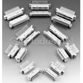
Conn Hard Metric F 120Signal/60Ground POS 2.5mm Press Fit RA Thru-Hole
Part Number
973024
Price
Request Quote
Manufacturer
ERNI ELECTRONICS
Lead Time
Request Quote
Category
Connectors » Connector Backplane
Specifications
Manufacturer
ERNI Electronics
Manufacturers Part #
973024
Sub-Category
Backplane Connectors
Factory Pack Quantity
32
Datasheet

Extracted Text
® ERmet ZD www.erni.com Catalog E 074505 04/07 Edition 7 www.erni.com Catalog E 074505 04/07 Edition 7 ERmet ZD High Speed Differential Hard Metric Connector System Table of Contents ERmet ZD High Speed Differential Hard Metric Connector System . . . . . . . . . . . . . . . . . . . . . . . . . . . . . . . . . . . . . . . . . . . . . . . . . .2 Electrical and Mechanical Characteristics . . . . . . . . . . . . . . . . . . . . . . . . . . . . . . . . . . . . . . . . . . . . . . . . . . . . . . . . . . . . . . . . . . . . .3 Right Angle Female Connectors 4 Pair . . . . . . . . . . . . . . . . . . . . . . . . . . . . . . . . . . . . . . . . . . . . . . . . . . . . . . . . . . . . . . . . . . . . . . .5 Right Angle Female Connectors 4 Pair Ordering Information . . . . . . . . . . . . . . . . . . . . . . . . . . . . . . . . . . . . . . . . . . . . . . . . . . . . . .6 Right Angle Female Connectors 3 Pair . . . . . . . . . . . . . . . . . . . . . . . . . . . . . . . . . . . . . . . . . . . . . . . . . . . . . . . . . . . . . . . . . . . . . . .7 Right Angle Female Connectors 3 Pair Ordering Information . . . . . . . . . . . . . . . . . . . . . . . . . . . . . . . . . . . . . . . . . . . . . . . . . . . . . .8 Right Angle Female Connectors 2 Pair . . . . . . . . . . . . . . . . . . . . . . . . . . . . . . . . . . . . . . . . . . . . . . . . . . . . . . . . . . . . . . . . . . . . . . .9 Right Angle Female Connectors 2 Pair Ordering Information . . . . . . . . . . . . . . . . . . . . . . . . . . . . . . . . . . . . . . . . . . . . . . . . . . . . .10 Vertical Male Connectors 4 Pair . . . . . . . . . . . . . . . . . . . . . . . . . . . . . . . . . . . . . . . . . . . . . . . . . . . . . . . . . . . . . . . . . . . . . . . . . . .11 Vertical Male Connectors 4 Pair Ordering Information . . . . . . . . . . . . . . . . . . . . . . . . . . . . . . . . . . . . . . . . . . . . . . . . . . . . . . . . . . .12 Vertical Male 4 Pair Cable Headers . . . . . . . . . . . . . . . . . . . . . . . . . . . . . . . . . . . . . . . . . . . . . . . . . . . . . . . . . . . . . . . . . . . . . . . . .14 Vertical Male 4 Pair Cable Headers Ordering Information . . . . . . . . . . . . . . . . . . . . . . . . . . . . . . . . . . . . . . . . . . . . . . . . . . . . . . . .15 Vertical Male Connectors 3 Pair . . . . . . . . . . . . . . . . . . . . . . . . . . . . . . . . . . . . . . . . . . . . . . . . . . . . . . . . . . . . . . . . . . . . . . . . . . .16 Vertical Male Connectors 3 Pair Ordering Information . . . . . . . . . . . . . . . . . . . . . . . . . . . . . . . . . . . . . . . . . . . . . . . . . . . . . . . . . . .17 Vertical Male Connectors 2 Pair . . . . . . . . . . . . . . . . . . . . . . . . . . . . . . . . . . . . . . . . . . . . . . . . . . . . . . . . . . . . . . . . . . . . . . . . . . .19 Vertical Male Connectors 2 Pair Ordering Information . . . . . . . . . . . . . . . . . . . . . . . . . . . . . . . . . . . . . . . . . . . . . . . . . . . . . . . . . . .20 Right Angle Male Connectors 4 Pair . . . . . . . . . . . . . . . . . . . . . . . . . . . . . . . . . . . . . . . . . . . . . . . . . . . . . . . . . . . . . . . . . . . . . . . .21 Right Angle Male Connectors 4 Pair Ordering Information . . . . . . . . . . . . . . . . . . . . . . . . . . . . . . . . . . . . . . . . . . . . . . . . . . . . . . .22 Right Angle Male Connectors 3 Pair . . . . . . . . . . . . . . . . . . . . . . . . . . . . . . . . . . . . . . . . . . . . . . . . . . . . . . . . . . . . . . . . . . . . . . . .23 Right Angle Male Connectors 3 Pair Ordering Information . . . . . . . . . . . . . . . . . . . . . . . . . . . . . . . . . . . . . . . . . . . . . . . . . . . . . . .24 Right Angle Male Connectors 2 Pair . . . . . . . . . . . . . . . . . . . . . . . . . . . . . . . . . . . . . . . . . . . . . . . . . . . . . . . . . . . . . . . . . . . . . . . .25 Right Angle Male Connectors 2 Pair Ordering Information . . . . . . . . . . . . . . . . . . . . . . . . . . . . . . . . . . . . . . . . . . . . . . . . . . . . . . .26 Vertical Female Connectors 4 Pair . . . . . . . . . . . . . . . . . . . . . . . . . . . . . . . . . . . . . . . . . . . . . . . . . . . . . . . . . . . . . . . . . . . . . . . . .27 Vertical Female Connectors 4 Pair Ordering Information . . . . . . . . . . . . . . . . . . . . . . . . . . . . . . . . . . . . . . . . . . . . . . . . . . . . . . . . .28 Cable System . . . . . . . . . . . . . . . . . . . . . . . . . . . . . . . . . . . . . . . . . . . . . . . . . . . . . . . . . . . . . . . . . . . . . . . . . . . . . . . . . . . . . . . .29 ERmet ZD Cable 5 Wafer . . . . . . . . . . . . . . . . . . . . . . . . . . . . . . . . . . . . . . . . . . . . . . . . . . . . . . . . . . . . . . . . . . . . . . . . . . . . . . . .30 ERmet ZD Cable 10 Wafer . . . . . . . . . . . . . . . . . . . . . . . . . . . . . . . . . . . . . . . . . . . . . . . . . . . . . . . . . . . . . . . . . . . . . . . . . . . . . . .31 Cable Assemblies . . . . . . . . . . . . . . . . . . . . . . . . . . . . . . . . . . . . . . . . . . . . . . . . . . . . . . . . . . . . . . . . . . . . . . . . . . . . . . . . . . . . .31 Application Tooling, Equipment and Testing . . . . . . . . . . . . . . . . . . . . . . . . . . . . . . . . . . . . . . . . . . . . . . . . . . . . . . . . . . . . . . . . . .32 Mating Conditions . . . . . . . . . . . . . . . . . . . . . . . . . . . . . . . . . . . . . . . . . . . . . . . . . . . . . . . . . . . . . . . . . . . . . . . . . . . . . . . . . . . . .34 Recommended PCB Layout . . . . . . . . . . . . . . . . . . . . . . . . . . . . . . . . . . . . . . . . . . . . . . . . . . . . . . . . . . . . . . . . . . . . . . . . . . . . .35 Antipad Size . . . . . . . . . . . . . . . . . . . . . . . . . . . . . . . . . . . . . . . . . . . . . . . . . . . . . . . . . . . . . . . . . . . . . . . . . . . . . . . . . . . . . . . . . .40 Additional Mechanical Features . . . . . . . . . . . . . . . . . . . . . . . . . . . . . . . . . . . . . . . . . . . . . . . . . . . . . . . . . . . . . . . . . . . . . . . . . . .41 Part Number Index . . . . . . . . . . . . . . . . . . . . . . . . . . . . . . . . . . . . . . . . . . . . . . . . . . . . . . . . . . . . . . . . . . . . . . . . . . . . . . . . . . . . .44 Catalog E 074505 04/07 Edition 7 www.erni.com 1 ERmet ZD High Speed Differential Hard Metric Connector System ERmet ZD Male and Female Module with Pressfit Termination Description Technical Features The ERmet ZD is specifically designed for high speed • Design: Wafers with individually shielded pairs of contacts. differential signaling in telecom applications at data rates of up • Contacts: Low noise, dual beam, leaf contacts with one to 5 Gbits/second. This robust, high performance, modular ground blade for every pair of signals. connector system is also designed to be used in conjunction • Wafer pitch: 2.5 mm from wafer to wafer. with the 2 mm Hard Metric (IEC 61076-4-101) family of • Pitch between signal pins: 1.5 mm between pairs connectors. It shares the chassis and board design features (within wafer). along with common layout references. • Pitch between pairs: 4.5 mm (within wafer). The connector meets the electrical performance requirements • Ground arrangement: In line with signals at termination and of high speed, low voltage differential signaling. The ERmet ZD surrounding shield. connector family is available in pressfit versions. The back- • Multiline Crosstalk < 3% at 100 ps plane module is a male pin header that has three mating • Differential Impedance: 100 Ω ±10% levels. The ground shield and signal pins mate sequentially at • Power Modules: Closed entry, vertical female backplane 1.5 mm intervals. modules with stamped blades. The robust mechanical design and excellent signal integrity • Alignment Features: Improved pre-alignment guide and are a result of the internal differential shielding scheme and the polarizing features, 4 rigid blades for all modules. “L” shaped male shield blades. The inherently rigid male • Modularity: Modules are available in two widths and a shields stand higher than the signal pins and surround each variety of lengths to integrate within typical Eurocard pair. An improved guidance feature completes the rugged designs utilizing 5 and 8 row, 2 mm HM connectors to mechanical design. IEC 61076-4-101. Optimized grid design to improve the RF characteristics. Easy and economical trace routing achieved by in line-design of signal and ground pins. Simulation models available upon request. 2 Catalog E 074505 04/07 Edition 7 www.erni.com ERmet ZD High Speed Differential Hard Metric Connector System Electrical and Mechanical Characteristics Standard Pressfit Male- and Female Number of pins 2-, 3- and 4-pair Technical data Climate category DIN EN 60068-1 -55/125/56 test b Temperature range -55/125 °C Current rating IEC60512 By ambient temperature: test 5b 20 °C 0.9 A 70 °C 0.7 A 100 °C 0.4 A Clearance and creepage 0.5 mm distance Voltage rating IEC 60664 Has to be determined according to client-specific using case (degree of environmental pollu- tion) according to IEC 60664 Dielectric strength IEC 60512 contact pair - contact pair 500 V rms test 4a contact pair - shield 500 V rms Contact resistance IEC 60512 < 50 mΩ (Signal) test 2a < 15 mΩ (Shield) 4 Insulation resistance IEC 60512 > 10 MΩ test 3a Vibration, sine IEC 60512 10 – 2000 Hz test 6d 20 g Contact interruption (while IEC 60512 < 1 µs vibration test) test 2e Shock, halfsine IEC 60512 50 g test 6c 11 ms Contact interruption (while IEC 60512 < 1 µs shock test) test 2e Mechanical operation IEC 60512 > 250 mating cycles (mating cycles) test 9a Insertion and withdrawal IEC 60512 Insertion force: max. 0.7 N/pin (Signal) force test 13b max. 0.9 N/pin (Shield) Withdrawal force: min. 0.15 N/pin Gauge retention force IEC 60512 > 0.2 N test 16e Catalog E 074505 04/07 Edition 7 www.erni.com 3 ERmet ZD High Speed Differential Hard Metric Connector System Electrical and Mechanical Characteristics Standard Pressfit Male- and Female Number of pins 2-, 3- and 4-pair Signal transmission data Multiline Crosstalk < 3% at 100 ps Insertion Loss < 1 dB up to 3 GHz Differential impedance 100 Ω ±10% Propagation delay A pin 197 ±10 ps B pin 107 ±10 ps C pin 125 ±10 ps D pin 134 ±10 ps E pin 157 ±10 ps F pin 166 ±10 ps G pin 187 ±10 ps H pin 199 ±10 ps Process-conditions Press-in force 36 N/pin Warning Soldering of pressfit connectors not recommended. Materials Housing: LCP Plastic material (symbol) CTI value IEC 112 CTI 175 UL flame rating UL 94 V-0 UL file E83005 Contact and mating area Base material Cu alloy min. 0.65 µm PdNi + 0.1 µm Au over 2 - 3 µm Ni Plating 0.76 µm Au over 1.27 µm Ni (Right Angle Male RoHS 5/6) Termination area Base material Cu alloy Plating 0.5 - 2 µm Sn matt over 2 - 3 µm Ni 0.5 µm SnPb over 1.27 µm Ni (Right Angle Male RoHS 5/6) Environment compatibility Recycling no flame-retardent additives, no toxic additives, allow easy recycling Product-approval UL E84703 4 Catalog E 074505 04/07 Edition 7 www.erni.com gh gh ef ef cd cd ab ab ERmet ZD High Speed Differential Hard Metric Connector System Right Angle Female Connectors 4 Pair The ERmet ZD 4 pair female connector provides in the 10 wafer version 40 contact pairs (80 signal contacts and 40 ground contacts). The female pair 4 is available with pressfit termination. Additionally, the ERmet ZD 4 pair female connector has four pre-alignment pegs which provide easier alignment, improved rigidity and reliable polarisation. The layout grid facilitates integration with conventional 2 mm HM (IEC 061076-4-101) connectors. Dimensional Drawing 9x2.5= 22,5 0,75 2,5 h g f e d c b a 10 1 EE-Zone für durchkontaktierte ±0.05 Löcher ş 0.6 compliant zone for through hole ±0.05 ş 0.6 0,1 15,7 1,8 Lochbild für Leiterplatte Board hole pattern (Bestückungsseite) (Component mounting side) 24,95 -0,1 0,1 2,4 alle Löcher - all holes 9 x 2.5 =() 22,5 0.05 h g 2,5 1) f e h d g c f b e a d c b a 10 1 21,4 -0,1 Firmensignet Position ±0.05 1) ş0.6 Durchmesser des metallisierten Loches Date Code Id.-Nr. ±0.05 ş0.6 Diameter of finished plated-through hole ±0.02 ş0.7 Bohrungsdurchmesser des Loches ±0.02 All dimensions in mm ş0.7 Diameter of drilled hole Catalog E 074505 04/07 Edition 7 www.erni.com 5 1,5 1,5 4,5 10,8 -0,2 1,5 19,4 0,1 27,9 1 1,5 1,5 11x 1.5 =() 16,5 1 XXXXXXX ERNI 973032 ERmet ZD High Speed Differential Hard Metric Connector System Right Angle Female Connectors 4 Pair Ordering Information Configuration Length Pin Termination Termination Used For No. of Pins Part Number Configuration Tail Length h g f e d c b a 10 1 4 Pair / 25 mm 40 pairs - Pressfit 1.8 mm Zone 2 120 973032 10 wafers 80 signals / 40 grounds * 4 Pair / 30 mm 48 pairs - Pressfit 1.8 mm – 144 973099 12 wafers 96 signals / 48 grounds 4 Pair / 37.5 mm 60 pairs - Pressfit 1.8 mm 180 973024* 15 wafers 120 signals / 60 grounds * Parts available as kit. 6 Catalog E 074505 04/07 Edition 7 www.erni.com ef ef cd cd ab ab ERmet ZD High Speed Differential Hard Metric Connector System Right Angle Female Connectors 3 Pair The ERmet ZD 3 pair female connector provides in the 10 wafer version 30 contact pairs (60 signal contacts and 30 ground contacts). The female 3 pair is available with pressfit termination. Additionally, the ERmet ZD 3 pair female connector has four pre-alignment pegs which provide easier alignment, improved rigidity and reliable polarisation. The layout grid facilitates integration with conventional 2 mm HM (IEC 061076-4-101) connectors. Dimensional Drawing 9x2.5= 22,5 0,75 2,5 f e d c b a 10 1 EE-Zone für durchkontaktierte ±0.05 Löcher ş 0.6 compliant zone for through hole ±0.05 ş 0.6 0,1 11,2 1,8 Lochbild für Leiterplatte Board hole pattern (Bestückungsseite) (Component mounting side) 24,95 -0,1 0,1 2,4 alle Löcher - all holes 9 x 2.5 =() 22,5 0.05 f 2,5 e 1) d c b f a e d c b a 10 1 16,9 -0,1 Firmensignet Position Ident-Nr. Date Code ±0.05 1) ş0.6 Durchmesser des metallisierten Loches ±0.05 ş0.6 Diameter of finished plated-through hole ş0.7 Bohrungsdur ±0.02 chmesser des Loches All dimensions in mm ±0.02 ş0.7 Diameter of drilled hole Catalog E 074505 04/07 Edition 7 www.erni.com 7 1,5 4,5 1,5 14,9 10,8 -0,2 1,5 0,1 23,3 1 1,5 1,5 8x 1.5 =() 12 1 XXXXXXX ERNI 973028 ERmet ZD High Speed Differential Hard Metric Connector System Right Angle Female Connectors 3 Pair Ordering Information Configuration Length Pin Termination Termination Used For No. of Pins Part Number Configuration Tail Length f e d c b a 10 1 3 Pair / 25 mm 30 pairs - Pressfit 1.8 mm ADF 90 973028 10 wafers 60 signals / 30 grounds f e d c b a 15 1 3 Pair / 37.5 mm 45 pairs - Pressfit 1.8 mm – 135 973020 15 wafers 90 signals / 45 grounds 8 Catalog E 074505 04/07 Edition 7 www.erni.com cd ab ERmet ZD High Speed Differential Hard Metric Connector System Right Angle Female Connectors 2 Pair The ERmet ZD 2 pair female connector provides in the 10 wafer version 20 contact pairs (40 signal contacts and 20 ground contacts). The female 2 pair is available with pressfit termination. Additionally, the ERmet ZD 2 pair female connector has four pre-alignment pegs which provide easier alignment, improved rigidity and reliable polarisation. The layout grid facilitates integration with conventional 2 mm HM (IEC 061076-4-101) connectors. Dimensional Drawing 9x2,5= 22,5 0,75 2,5 d c b a 10 1 8,56 Lochbild für Leiterplatte Board hole pattern (Bestückungsseite) (Component mounting side) 0,1 1,8 24,95 -0,1 0,1 2,4 alle Löcher - all holes 9 x 2,5 =() 22,5 cd 0.05 d c 2,5 1) ab b a d c b Position a 13,35 -0,1 10 1 Id.-Nr. Firmensignet Date Code EE-Zone für durchkontaktierte Löcher ş0.6 ±0.05 ±0.05 1) ş0.6 Durchmesser des metallisierten Loches compliant zone for through hole ±0.05 ş0.6 Diameter of finished plated-through hole ş0.6 ±0.05 ±0.02 ş0.7 Bohrungsdurchmesser des Loches ±0.02 ş0.7 Diameter of drilled hole All dimensions in mm Catalog E 074505 04/07 Edition 7 www.erni.com 9 1,5 4,5 11,35 1,5 10,8 1,5 -0,2 0,1 1 18,9 1,5 1,5 5 x 1,5 =() 7,5 1 XXXXXXX ERNI 973046 ERmet ZD High Speed Differential Hard Metric Connector System Right Angle Female Connectors 2 Pair Ordering Information Configuration Length Pin Termination Termination Used For No. of Pins Part Number Configuration Tail Length d c b a 10 1 2 pair / 25 mm 20 pairs - Pressfit 1.8 mm – 60 973046 10 wafers 40 signals / 20 grounds 10 Catalog E 074505 04/07 Edition 7 www.erni.com ab ab cd cd ef ef gh gh ERmet ZD High Speed Differential Hard Metric Connector System Vertical Male Connectors 4 Pair The ERmet ZD 4 pair male connector provides in the 10 wafer version 40 contact pairs (80 signal contacts and 40 ground contacts). This series supports three levels of sequential mating. The male 4 pair is available with pressfit termination. The "L" shaped shields are robust mechanical structures that provide an ideal differential environment as well as protecting the signal pins and resisting deflection that could cause stubbing. Various module length are offered in four pair wide configura- tion. The layout grid facilitates integration with conventional 2 mm HM (IEC 061076-4-101) connectors. Dimensional Drawing 23,4 -0,1 Id.-Nr. Date Code EE-Zone für durchkontaktierte ±0.05 Löcher ş 0.6 compliant zone for through hole ş 0.6 ±0.05 Lochbild für Leiterplatte Board hole pattern 10 9 8 7 6 5 4 3 2 1 (Bestückungsseite) (Component mounting side) alle Löcher - all holes a 9 x 2.5 = () 22,5 b 0.05 c 2,5 1) d e f g h a b c d e f 2,5 g h 9x2.5= 22,5 0,75 24,95 -0,1 10 9 8 7 6 5 4 3 2 1 ±0.05 1) ş0.6 Durchmesser des metallisierten Loches ±0.05 ş0.6 Diameter of finished plated-through hole ±0.02 ş0.7 Bohrungsdurchmesser des Loches ±0.02 All dimensions in mm ş0.7 Diameter of drilled hole Catalog E 074505 04/07 Edition 7 www.erni.com 11 1,5 4,5 5,7 0,2 () 1,7 3 -0,1 0,1 6,35 0,05 13,4 1,5 11x 1.5 =() 16,5 XXXXXXX ERNI 973031 ab cd ef gh ab cd ef gh ab cd ef gh ERmet ZD High Speed Differential Hard Metric Connector System Vertical Male Connectors 4 Pair Ordering Information Configuration Length Pin Termination Termination Used For No. of Pins Part Number Configuration Tail Length ERmet a BBBBBB BBB B b BBBBBBBBB B YYYYYYYYY Y c B B B B B B BBB B d B B B B B B B B B B YYYYYYYYY Y e B B B BB B BBB B f B B BB BB B B B B Y Y Y Y Y Y Y Y Y Y g B B B B B B BB B B h BBBBBBB BB B Y Y Y Y Y Y Y Y Y Y 10 9 8 7 6 5 4 3 2 1 4 Pair / 25 mm 40 pairs - Pressfit 1.7 mm – 120 973061 10 wafers 80 signals / 40 grounds a DDDDDD DDD D b DDDDDDDDD D YYYYYYYYY Y c D D D D D D DDD D d D D D D D D D D D D YYYYYYYYY Y e D D D DD D DDD D f D D DD DD D D D D Y Y Y Y Y Y Y Y Y Y g D D D D D D DD D D h DDDDDDD DD D Y Y Y Y Y Y Y Y Y Y 10 9 8 7 6 5 4 3 2 1 4 Pair / 25 mm 40 pairs - Pressfit 3.7 mm Zone 2 120 973031 10 wafers 80 signals / 40 grounds a D D D DDDDD DDD D b D D D DDDDDDDD D Y Y Y YYYYYYYY Y c D D D D D D D D DDD D d D D D D D D D D D D D D Y Y Y YYYYYYYY Y e D D D D D DD D DDD D f D D D D DD DD D D D D Y Y Y Y Y Y Y Y Y Y Y Y g D D D D D D D D DD D D h D D D DDDDDD DD D Y Y Y Y Y Y Y Y Y Y Y Y 12 11 10 9 8 7 6 5 4 3 2 1 4 Pair / 30 mm 48 pairs - Pressfit 3.7 mm – 144 973096 12 wafers 96 signals / 48 grounds Signal Pins Shielding Pins YZ AB C D E F 12 Catalog E 074505 04/07 Edition 7 www.erni.com 0,2 1,7 0,1 3,8 () 3 -0,1 0,1 5,3 0,2 2,5 0,2 3,7 Bezugsebene Tiefe Datum plane depth 0,2 1,7 0,1 () 6,35 () 3 -0,1 0,2 2,5 Bezugsebene Tiefe Datum plane depth ab cd ef gh ERmet ZD High Speed Differential Hard Metric Connector System Vertical Male Connectors 4 Pair Ordering Information Configuration Length Pin Termination Termination Used For No. of Pins Part Number Configuration Tail Length a D D D D D D DDDDD DDD D b D D D D D D DDDDDDDD D Y Y Y Y Y Y YYYYYYYY Y c D D D D D D D D D D D DDD D d D D D D D D D D D D D D D D D Y Y Y Y Y Y YYYYYYYY Y e D D D D D D D D DD D DDD D f D D D D D D D DD DD D D D D Y Y Y Y Y Y Y Y Y Y Y Y Y Y Y g D D D D D D D D D D D DD D D h D D D D D D DDDDDD DD D Y Y Y Y Y Y Y Y Y Y Y Y Y Y Y 15 14 13 12 11 10 9 8 7 6 5 4 3 2 1 4 Pair / 37.5 mm 60 pairs - Pressfit 3.7 mm – 180 973023 15 wafers 120 signals / 60 grounds Signal Pins Shielding Pins YZ AB C D E F Catalog E 074505 04/07 Edition 7 www.erni.com 13 0,2 1,7 0,1 3,8 () 3 -0,1 0,1 5,3 0,2 2,5 0,2 3,7 Bezugsebene Tiefe Datum plane depth 0,2 1,7 0,1 () 6,35 () 3 -0,1 0,2 2,5 Bezugsebene Tiefe Datum plane depth ab ab cd cd ef ef gh gh ERmet ZD High Speed Differential Hard Metric Connector System Vertical Male 4 Pair Cable Headers The ERmet ZD cable assembly combines high data rate digital cabling technology with the ERmet ZD high-speed connector to offer an interconnect that delivers high signal fidelity and reliability at backdrill of 5 Gbit/s or higher. The vertical male 4 pair cable header is available with latch for the 5 wafer cable system. Dimensional Drawing 25,2 Ident-Nr. Date Code EE-Zone für durchkontaktierte ±0.05 Löcher ş 0.6 compliant zone for through hole ±0.05 ş 0.6 Lochbild für Leiterplatte Board hole pattern 10 9 8 7 6 5 4 3 2 1 (Bestückungsseite) (Component mounting side) alle Löcher - all holes 9 x 2.5 = 22,5 b 0.05 c 2,5 1) d e f g a h b c d e 2,5 f g 9 x 2.5 = 22,5 0,75 h 24,95 -0,1 10 9 8 7 6 5 4 3 2 1 ±0.05 1) ş0.6 Durchmesser des metallisierten Loches ş0.6 Diameter of finished plated-thr ±0.05 ough hole ±0.02 ş0.7 Bohrungsdurchmesser des Loches ş0.7 Diameter of drilled hole ±0.02 All dimensions in mm 14 Catalog E 074505 04/07 Edition 7 www.erni.com 1,5 4,2 4,5 0,2 2,5 3 -0,1 6,35 0,1 0,05 13,4 1,5 11x 1.5 = 16,5 XXXXXXX ERNI 174234 ab cd ef gh ERmet ZD High Speed Differential Hard Metric Connector System Vertical Male 4 Pair Cable Headers Ordering Information Configuration Length Pin Termination Termination No. of Pins Part Number Configuration Tail Length 4 Pair / 25 mm 40 pairs - Pressfit 1.7 mm 120 244766 10 wafers 80 signals / 40 grounds a FFFFFFFFFF b FFFFFFFFFF ZZZZZZZZZZ c FFFFFFFFFF d FFFFFFFFFF ZZZZZZZZZZ e FFFFFFFFFF f FFFFFFFFFF ZZZZZZZZZZ g FFFFFFFFFF h FFFFFFFFFF ZZZZZZZZZZ 10 9 8 7 6 5 4 3 2 1 4 Pair / 25 mm 40 pairs - Pressfit 2.5 mm 120 174234 10 wafers 80 signals / 40 grounds Signal Pins Shielding Pins YZ AB C D E F Catalog E 074505 04/07 Edition 7 www.erni.com 15 0,2 1,7 0,1 3,8 () 3 -0,1 0,1 5,3 0,2 2,5 0,2 3,7 Bezugsebene Tiefe Datum plane depth 0,2 1,7 0,1 () 6,35 () 3 -0,1 0,2 2,5 Bezugsebene Tiefe Datum plane depth ab ab cd cd ef ef ERmet ZD High Speed Differential Hard Metric Connector System Vertical Male Connectors 3 Pair The ERmet ZD 3 pair male connector provides in the 10 wafer version 30 contact pairs (60 signal contacts and 30 ground contacts). This series supports three levels of sequential mating. The male 3 pair is available with pressfit termination. The "L" shaped shields are robust mechanical structures that provide an ideal differential environment as well as protecting the signal pins and resisting deflection that could cause stubbing. Various module length are offered in three pair wide configu- ration. The three pair wide version is ideal for Eurocard back- plane designs with 2 mm card spacing. Dimensional Drawing Ident-Nr. Date/Code 18,9 -0,1 EE-Zone für durchkontaktierte ±0.05 Löcher ş 0.6 compliant zone for through hole ±0.05 ş 0.6 Lochbild für Leiterplatte Board hole pattern 10 9 8 7 6 5 4 3 2 1 (Bestückungsseite) (Component mounting side) alle Löcher - all holes a 9 x 2.5 =() 22,5 b 0.05 c 2,5 1) d e f a b 2,5 c d 9x2.5= 22,5 0,75 e f 24,95 -0,1 10 9 8 7 6 5 4 3 2 1 ±0.05 1) ş0.6 Durchmesser des metallisierten Loches ±0.05 ş0.6 Diameter of finished plated-through hole ±0.02 ş0.7 Bohrungsdurchmesser des Loches ±0.02 ş0.7 Diameter of drilled hole All dimensions in mm 16 Catalog E 074505 04/07 Edition 7 www.erni.com 1,5 4,5 5,7 0,2 1,7 3 -0,1 0,1 6,35 0,05 13,4 1,5 8 x 1,5 =() 12 XXXXXXX ERNI 973027 ab cd ef ab cd ef ab cd ef ERmet ZD High Speed Differential Hard Metric Connector System Vertical Male Connectors 3 Pair Ordering Information Configuration Length Pin Termination Termination Used For No. of Pins Part Number Configuration Tail Length a BBBBBB BBB B b BBBBBBBBB B YYYYYYYYY Y c B B B B B B BBB B d B B B B BBB B B B YYYYYYYYY Y e B B B B B B BBB B f B B B B BBB B B B YYYYYYYYY Y 10 9 8 7 6 5 4 3 2 1 3 Pair / 25 mm 30 pairs - Pressfit 1.7 mm – 90 973062 10 wafers 60 signals / 30 grounds a F F F F F F F F F F b F F F F F F F F F F Z Z Z Z Z Z Z Z Z Z c F F F F F F F F F F d F F F F F F F F F F Z Z Z Z Z Z Z Z Z Z e F F F F F F F F F F f F F F F F F F F F F Z Z Z Z Z Z Z Z Z Z 10 9 8 7 6 5 4 3 2 1 3 Pair / 25 mm 30 pairs - Pressfit 2.5 mm – 90 223396 10 wafers 60 signals / 30 grounds a DDDDDD DDD D b DDDDDDDDD D YYYYYYYYY Y c D D D D D D DDD D d D D D D DDD D D D YYYYYYYYY Y e D D D D D D DDD D f D D D D DDD D D D YYYYYYYYY Y 10 9 8 7 6 5 4 3 2 1 3 Pair / 25 mm 30 pairs - Pressfit 3.7 mm – 90 973027 10 wafers 60 signals / 30 grounds Signal Pins Shielding Pins YZ AB C D E F Catalog E 074505 04/07 Edition 7 www.erni.com 17 0,2 1,7 0,1 3,8 () 3 -0,1 0,1 5,3 0,2 2,5 0,2 3,7 Bezugsebene Tiefe Datum plane depth 0,2 1,7 0,1 () 6,35 () 3 -0,1 0,2 2,5 Bezugsebene Tiefe Datum plane depth ab cd ef ERmet ZD High Speed Differential Hard Metric Connector System Vertical Male Connectors 3 Pair Ordering Information Configuration Length Pin Termination Termination Used For No. of Pins Part Number Configuration Tail Length a DDDDD DDDDDD DDD D b DDDDD DDDDDDDDD D YYYYY YYYYYYYYY Y c D D D D D D D D D D D DDD D d D D D D D D D D D DDD D D D YYYYY YYYYYYYYY Y e D D D D D D D D D D D DDD D f D D D D D D D D D DDD D D D YYYYY YYYYYYYYY Y 15 14 13 12 11 10 9 8 7 6 5 4 3 2 1 3 Pair / 37.5 mm 45 pairs - Pressfit 3.7 mm – 135 973019 15 wafers 90 signals / 45 grounds Signal Pins Shielding Pins YZ AB C D E F 18 Catalog E 074505 04/07 Edition 7 www.erni.com 0,2 1,7 0,1 3,8 () 3 -0,1 0,1 5,3 0,2 2,5 0,2 3,7 Bezugsebene Tiefe Datum plane depth 0,2 1,7 0,1 () 6,35 () 3 -0,1 0,2 2,5 Bezugsebene Tiefe Datum plane depth ab ab cd cd ERmet ZD High Speed Differential Hard Metric Connector System Vertical Male Connectors 2 Pair The ERmet ZD 2 pair male connector provides in the 10 wafer version 20 contact pairs (40 signal contacts and 20 ground contacts). This series supports three levels of sequential mating. The male 2 pair is available with pressfit termination. The "L" shaped shields are robust mechanical structures that provide an ideal differential environment as well as protecting the signal pins and resisting deflection that could cause stubbing. Various module length are offered in two pair wide configura- tion. The two pair wide version is ideal for applications in combination with ERmet 5+2 connectors because of the same width of 15.4 mm. Dimensional Drawing Ident-Nr. Date/Code 15,4 -0,1 EE-Zone für durchkontaktierte Löcher ş 0.6 ±0.05 compliant zone for through hole ±0.05 ş 0.6 Lochbild für Leiterplatte Board hole pattern (Bestückungsseite) (Component mounting side) 10 9 8 7 6 5 4 3 2 1 alle Löcher - all holes 9 x 2.5 =() 22,5 a b 2,5 c 1) d a 2,5 b 9x2.5= 22,5 0,75 c d 24,95 -0,1 10 9 8 7 6 5 4 3 2 1 ±0.05 1) ş0.6 Durchmesser des metallisierten Loches ±0.05 ş0.6 Diameter of finished plated-through hole ±0.02 ş0.7 Bohrungsdurchmesser des Loches ±0.02 ş0.7 Diameter of drilled hole All dimensions in mm Catalog E 074505 04/07 Edition 7 www.erni.com 19 1,5 4,5 5,7 0,6 0,2 1,7 3 -0,1 0,1 6,35 0,05 13,4 1,5 5x 1,5 =() 7,5 XXXXXXX ERNI 973056 ab cd ab cd ab cd ERmet ZD High Speed Differential Hard Metric Connector System Vertical Male Connectors 2 Pair Ordering Information Configuration Length Pin Termination Termination Used For No. of Pins Part Number Configuration Tail Length a AAAAAA AAA A b AAAAAAAAA A YYYYYYYYY Y c A A A A A A AAA A d A A A A AAA A A A YYYYYYYYY Y 10 9 8 7 6 5 4 3 2 1 2 pair / 25 mm 20 pairs - Pressfit 1.7 mm – 60 973080 10 wafers 40 signals / 20 grounds a BBBBBB BBB B b BBBBBBBBB B YYYYYYYYY Y c B B B B B B BBB B d B B B B BBB B B B YYYYYYYYY Y 10 9 8 7 6 5 4 3 2 1 2 pair / 25 mm 20 pairs - Pressfit 1.7 mm – 60 973063 10 wafers 40 signals / 20 grounds a DDDDDD DDD D b DDDDDDDDD D YYYYYYYYY Y c D D D D D D DDD D d D D D D DDD D D D YYYYYYYYY Y 10 9 8 7 6 5 4 3 2 1 2 pair / 25 mm 20 pairs - Pressfit 3.7 mm – 60 973056 10 wafers 40 signals / 20 grounds Signal Pins Shielding Pins YZ AB C D E F 20 Catalog E 074505 04/07 Edition 7 www.erni.com 0,2 1,7 0,1 3,8 () 3 -0,1 0,1 5,3 0,2 2,5 0,2 3,7 Bezugsebene Tiefe Datum plane depth 0,2 1,7 0,1 () 6,35 () 3 -0,1 0,2 2,5 Bezugsebene Tiefe Datum plane depth ab cd ab ef cd gh ef gh ERmet ZD High Speed Differential Hard Metric Connector System Right Angle Male Connectors 4 Pair The ERmet ZD 4 pair right angle male connector provides in the 10 wafer version 40 contact pairs and is available with pressfit termination. The connector is designed for high speed differential applications and is an extension of the ERmet 2 mm HM product line. The 4 pair right angle male connector can be used as an ® AdvancedTCA Zone 3 connector in conjunction with the Zone 2 right angle female connector. Dimensional Drawing Ident-Nr. Date/Code 23,35 EE-Zone für durchkontaktierte ±0.05 Löcher ş 0.6 compliant zone for through hole ±0.05 ş 0.6 17,68 10 9 8 7 6 5 4 3 2 1 Lochbild für Leiterplatte Board hole pattern (Bestückungsseite) (Component mounting side) a b alle Löcher - all holes c 9 x 2,5 =() 22,5 d e 2,5 1) f g h a b 2,5 c d 9 x 2,5 = 22,5 0,75 e f 24,95 g h 10 9 8 7 6 5 4 3 2 1 ±0.05 1) ş0.6 Durchmesser des metallisierten Loches ±0.05 ş0.6 Diameter of finished plated-through hole ±0.02 ş0.7 Bohrungsdurchmesser des Loches ±0.02 ş0.7 Diameter of drilled hole All dimensions in mm Catalog E 074505 04/07 Edition 7 www.erni.com 21 1,5 4,5 5,7 17,2 2 1,5 6,35 6,9 34,55 1,5 11 x 1,5 = 16,5 XXXXXXX ERNI 973101 ab cd ef gh ERmet ZD High Speed Differential Hard Metric Connector System Right Angle Male Connectors 4 Pair Ordering Information Configuration Length Pin Termination Termination Used For No. of Pins Part Number Configuration Tail Length a FFFFFF FFF F b FFFFFFFFF F YYYYYYYYY Y c F F F F F F FFF F d F F F F FFF F F F YYYYYYYYY Y e FFFFFF FFF F f FFFFFFFFF F YYYYYYYYY Y g F F F F F F FFF F h F F F F FFF F F F YYYYYYYYY Y 10 9 8 7 6 5 4 3 2 1 4 Pair / 25 mm 40 pairs - Pressfit – – 120 973101 10 wafers 80 signals / 40 grounds Signal Pins Shielding Pins F Y 2,2 22 Catalog E 074505 04/07 Edition 7 www.erni.com 0,1 5,3 0,1 () 6,35 ab cd ab ef cd ef ERmet ZD High Speed Differential Hard Metric Connector System Right Angle Male Connectors 3 Pair The ERmet ZD 3 pair right angle male connector provides in the 10 wafer version 30 contact pairs and is available with pressfit termination. The connector is designed for high speed differential applications and is an extension of the ERmet 2 mm HM product line. Dimensional drawings and board hole pattern Ident-Nr. Date/Code 18,985 EE-Zone für durchkontaktierte ±0.05 Löcher ş 0.6 compliant zone for through hole ±0.05 ş 0.6 13,335 10 9 8 7 6 5 4 3 2 1 Lochbild für Leiterplatte Board hole pattern (Bestückungsseite) (Component mounting side) a b alle Löcher - all holes c 9 x 2,5 =() 22,5 d e f 2,5 1) 2,5 a b 9 x 2,5 = 22,5 0,75 c d 24,95 e f 10 9 8 7 6 5 4 3 2 1 ±0.05 1) ş0.6 Durchmesser des metallisierten Loches ±0.05 ş0.6 Diameter of finished plated-through hole ±0.02 ş0.7 Bohrungsdurchmesser des Loches ±0.02 ş0.7 Diameter of drilled hole All dimensions in mm Catalog E 074505 04/07 Edition 7 www.erni.com 23 1,5 4,5 5,7 12,7 2 1,5 6,35 6,9 30,05 1,5 1,5 5x 1,5 = () 3 XXXXXXX ERNI 204781 ab cd ef ERmet ZD High Speed Differential Hard Metric Connector System Right Angle Male Connectors 3 Pair Ordering Information Configuration Length Pin Termination Termination Used For No. of Pins Part Number Configuration Tail Length a FFFFFF FFF F b FFFFFFFFF F YYYYYYYYY Y c F F F F F F FFF F d F F F F FFF F F F YYYYYYYYY Y e FFFFFFFFF F f FFFFFFFFF F YYYYYYYYY Y 10 9 8 7 6 5 4 3 2 1 3 Pair / 25 mm 30 pairs - Pressfit – – 90 204781 10 wafers 60 signals / 30 grounds Signal Pins Shielding Pins F Y 2,2 24 Catalog E 074505 04/07 Edition 7 www.erni.com 0,1 5,3 0,1 () 6,35 ab cd ab cd ERmet ZD High Speed Differential Hard Metric Connector System Right Angle Male Connectors 2 Pair The ERmet ZD 2 pair right angle male connector provides in the 10 wafer version 20 contact pairs and is available with pressfit termination. The connector is designed for high speed differential applications and is an extension of the ERmet 2 mm HM product line. Dimensional Drawing Ident-Nr. Date/Code 15,485 EE-Zone für durchkontaktierte ±0.05 Löcher ş 0.6 compliant zone for through hole ş 0.6 ±0.05 9,81 10 9 8 7 6 5 4 3 2 1 Lochbild für Leiterplatte Board hole pattern (Bestückungsseite) (Component mounting side) a - all holes alle Löcher b 9 x 2.5 =() 22,5 c d 2,5 1) 2,5 9 x 2.5 = 22,5 0,75 24,9 a b c d 10 9 8 7 6 5 4 3 2 1 ±0.05 1) ş0.6 Durchmesser des metallisierten Loches ±0.05 ş0.6 Diameter of finished plated-through hole ±0.02 ş0.7 Bohrungsdurchmesser des Loches ±0.02 ş0.7 Diameter of drilled hole All dimensions in mm Catalog E 074505 04/07 Edition 7 www.erni.com 25 1,5 4,5 5,7 8,2 2 1,5 6,35 6,9 25,55 1,5 1,5 5x 1,5 =() 7,5 XXXXXXX ERNI 204780 ab cd ERmet ZD High Speed Differential Hard Metric Connector System Right Angle Male Connectors 2 Pair Ordering Information Configuration Length Pin Termination Termination Used For No. of Pins Part Number Configuration Tail Length a FFFFFF FFF F b FFFFFFFFF F YYYYYYYYY Y c F F F F F F FFF F d F F F F FFF F F F YYYYYYYYY Y 10 9 8 7 6 5 4 3 2 1 2 pair / 25 mm 20 pairs - Pressfit – – 60 204780 10 wafers 40 signals / 20 grounds Signal Pins Shielding Pins F Y 2,2 26 Catalog E 074505 04/07 Edition 7 www.erni.com 0,1 5,3 0,1 () 6,35 ERmet ZD High Speed Differential Hard Metric Connector System Vertical Female Connectors 4 Pair In addition to the four-pair connector modules specified for ® use in AdvancedTCA Zone 2, the product line includes two-pair and three-pair signal modules and coplanar connectors. A mezzanine style connector is also available in a four-pair version (vertical female pressfit). Dimensional Drawing EE-Zone für durchkontaktierte Löcher ş0,6±0,05 9x2.5= 22,5 compliant zone for through hole 0,75 2,5 ş0,6±0,05 Lochbild für Leiterplatte (Bestückungsseite) Board hole pattern (component mounting side) 1,8 15 1 alle Löcher - all holes 9x 2.5 =() 22,5 2,5 gh h g ef f e cd d c ab b a 10 1 24,95 1) 1) ş0,6±0,05 Durchmesser des metallisierten Loches ş0,6±0,05 diameter of finished plated-through hole ş0,7±0,02 Bohrungsdurchmesser des Loches ş0,7±0,02 diameter of drilled hole All dimensions in mm Catalog E 074505 04/07 Edition 7 www.erni.com 27 1,5 4,5 22,6 21,4 1,5 () 16,5 11x 1.5 = ERmet ZD High Speed Differential Hard Metric Connector System Vertical Female Connectors 4 Pair Ordering Information Configuration Length Pin Termination Termination Connector No. of Pins Part Number Configuration Tail Length Height * 4 Pair / 25 mm 40 pairs - Pressfit 1.8 mm 12 mm 120 134883 10 wafers 80 signals / 40 grounds 4 Pair / 25 mm 40 pairs - Pressfit 1.8 mm 15 mm 120 134974 10 wafers 80 signals / 40 grounds * Board-toBoard Distance: Female Connector Height + Male Connector Height = Board-to-Board Distance 12 mm + 3 mm = 15 mm 15 mm + 3 mm = 18 mm 28 Catalog E 074505 04/07 Edition 7 www.erni.com ERmet ZD High Speed Differential Hard Metric Connector System Cable System Conncector Specifications • Mating pin length: 3.8 - 5.3 mm • Operating temperature: -55 °C - +105 °C • Connector body: Glass filled LCP, UL 94 V-O • Contacts and Shield: Phosphor Bronze Mechanical Data • Mating force: Signal 0.7 N/pin (max.) Shield 0.9 N/pin (max.) • Withdrawal force: Signal 0.2 N/pin (max.) Shield 0.2 N/pin (max.) General Information Electrical Data ERmet ZD Cable Assemblies allow high speed digital signals • Current rating: 1.0 A @ 70 °C to be transmitted further and with superior signal fidelity. • Insulation resistance: This connector system has been optimized to transmit high Contact pair/Contact pair: 3000 MΩ (min.) speed differential signals between 2.5 to 10 Gbit/s. Contact pair/Shield: 4000 MΩ (min.) ERmet ZD Cable Assemblies come in a variety of different • Withstanding voltage: 500 V cable sizes, custom pin-out configurations, and are available • Connector impedance: 100 Ω ±5 Ω @ 100 ps rise time in either cable or backplane header compatible versions. EMI backshells can also be incorporated to provide a complete interconnect solution for external cabling requirements. This Performance level modular interconnect product family has been designated a common platform for interoperability testing by the 10 Gigabit • Multiline crosstalk: < 5% @ 100 ps rise time, 250 mV swing Ethernet Alliance XAUI Interoperability Group and 10 Gigabit Ethernet Consortium. The connector has also been selected as the backplane interconnect for the PICMG 3.X (ATCA) industry standard. Features • Low loss, low crosstalk, low skew • Controlled impedance through connector • Optimized grid design for enhanced electrical performance and trace routing • Integrated polarization, guidance and mechanical latching • Available versions: 4 pair cable header with latch for 5 wafer cable system 4 pair cable header without latch for 10 wafer cable system Catalog E 074505 04/07 Edition 7 www.erni.com 29 A H ERmet ZD High Speed Differential Hard Metric Connector System Cable Assemblies ERmet ZD Cable 5 Wafer This ERmet ZD cable is used for the 5 wafer cable system. The cables are available with or without latch. For use with Connector 244766 or 174234. Partnumber Cable System with Latch: 204685 25 1000 50 330 TAPE APPROX EVERY 325MM PUSH TO RELEASE HANDLE 50 TOP VIEW CABLE TYPE: DXSN2285 26 AWG. TWIN-AX 20X X1 X2 HA H A 1 1 5 5 FRONT VIEW X1 X2 H G F E D C B A H G F E D C B A NOTES: S4 S4 S3 S3 S2 S2 S1 S1 1 S4 S4 S3 S3 S2 S2 S1 S1 1 1. ALL GROUND WIRES TO BE ATTACHED TO SHIELDS 2 2 S8 S8 S7 S7 S6 S6 S5 S5 S8 S8 S7 S7 S6 S6 S5 S5 S12 S12 S11 S11 S10 S10 S9 S9 3 S12 S12 S11 S11 S10 S10 S9 S9 3 4 4 S16 S16 S15 S15 S14 S14 S13 S13 S16 S16 S15 S15 S14 S14 S13 S13 S20 S20 S19 S19 S18 S18 S17 S17 5 S20 S20 S19 S19 S18 S18 S17 S17 5 PINOUT LEFT SIDE VIEW PINOUT RIGHT SIDE VIEW 30 Catalog E 074505 04/07 Edition 7 www.erni.com A H LABEL TAPE TAPE A H ERmet ZD High Speed Differential Hard Metric Connector System Cable Assemblies ERmet ZD Cable 10 Wafer This ERmet ZD cable is used for the 10 wafer cable system. For use with Connector 973031 or 973061. Partnumber Cable System: 223325 500 25 50 300 TAPE APPROX. EVERY 300MM AS NEEDED 50 TOP VIEW CABLE TYPE: DXSN2285 26 AWG. TWIN-AX 40X X1 X2 H HA A 1 1 10 10 FRONT VIEW X1 X2 A H E D C B A H G F E D C B G F NOTES: S4 S1 S2 S2 S3 S3 S4 S4 1 S1 S1 S2 S2 S3 S3 S4 1 S1 1. ALL GROUND WIRES TO BE ATTACHED TO SHIELDS 2 S5 S5 S6 S6 S7 S7 S8 S8 2 S5 S5 S6 S6 S7 S7 S8 S8 3 S11 S11 S12 S12 3 S9 S9 S10 S10 S11 S11 S12 S12 S9 S9 S10 S10 4 S13 S13 S14 S14 S15 S15 S16 S16 4 S13 S13 S14 S14 S15 S15 S16 S16 S20 5 S17 S17 S18 S18 S19 S19 S20 S20 5 S17 S17 S18 S18 S19 S19 S20 6 S21 S24 S24 6 S21 S21 S22 S22 S23 S23 S24 S24 S21 S22 S22 S23 S23 S27 S27 S28 S28 7 S25 S26 S26 S27 S27 S28 S28 7 S25 S25 S26 S26 S25 8 S29 S29 S30 S31 S31 S32 S32 8 S29 S29 S30 S30 S31 S31 S32 S32 S30 9 S33 S33 S34 S34 S35 S35 S36 S36 9 S33 S33 S34 S34 S35 S35 S36 S36 10 S37 S37 S38 S38 S39 S39 S40 S40 10 S37 S37 S38 S38 S39 S39 S40 S40 PINOUT LEFT SIDE VIEW PINOUT LEFT SIDE VIEW Catalog E 074505 04/07 Edition 7 www.erni.com 31 A H LABEL TAPE TAPE ERmet ZD High Speed Differential Hard Metric Connector System Application Tooling, Equipment and Testing Evaluation Kits The two evaluation kits, singleline version and multiline version, are developed to measure the signal integrity behavior of the advanced differential pair connector system ERmet ZD. Each evaluation kit contains the test boards and a CD Rom with the description of the measurement set up and relevant technical information. The boards are designed in a manner that allows full de-embedding of the parasitic influence of the transmission lines and the SMA connectors on the board. This ensures properly measured values of the connector system itself without any negative influence of the test fixture. Measurements can be performed with a Time Domain Re- flectometer in the Time domain or a Vector Network Analyzer in the frequency domain. Configuration Part Number The multiline version is specially designed to determine the multiline crosstalk between up to 10 signal pairs 163211 and to measure a connector directly at its pins. The singleline version can be used to determine differential impedance of single signal pairs, crosstalk between 163210 two signal pairs, transmission and reflection behavior of single pairs and propagation delay of single pairs. Simulation Models The ERNI ERmet ZD simulation models are provided in two different formats: 1.Spice compatible models based on L, R, C and K elements in accordance to UC Berkeley Spice3f5 standard. 2.S-parameter data in Touchstone file format For each format, two different types of simulation models are given: 1.A set of very compact models, which represents only one signal pair (e.g. a-b) of the connector. These models should be used, if only the reflection behavior and the impedance matching of the connector should be analyzed. They do not slow down a simulator significantly. This modell is available on the ERNI web page. 2.A set of models which represent 3 wafers of the connector with each wafer containing 2, 3 or 4 signal pairs. This model family fully represents the connector behavior including: • impedance matching • crosstalk behavior • ground bounce This model is only available when the customer has signed an NDA. The usage of each model is explained in the header part of the appropriate library file. Configuration Part Number CD with Simulation Models for the ERmet ZD Connector System 144470 32 Catalog E 074505 04/07 Edition 7 www.erni.com ERmet ZD High Speed Differential Hard Metric Connector System Application Tooling, Equipment and Testing Modular Pressfit Tools ERmet ZD connectors can be end to end mounted in modular layout. To be able to pressfit the selected connector layout for your application in a rationalized way, we have designed the necessary pressfit tools to be modular too. This is true of the tools both for male connectors and for female connectors. The tool bases, also termed anvils, are fixed in a tool holder. Each connector module requires an appropriately sized tool module. Ordering Information Connector Type Wafer Part Number Part Number Upper Tool Lower Tool Right Angle Female Connectors 4 Pair 10 220629 220630 Right Angle Female Connectors 3 Pair 10 220634 220635 Right Angle Female Connectors 2 Pair 10 220637 220638 Verticale Male Connectors 4 Pair 10 220627 220628 Verticale Male Connectors 3 Pair 10 220633 220640 Verticale Male Connectors 2 Pair 10 220636 220639 Right Angle Male Connectors 4 Pair 10 220880 220630 Right Angle Male Connectors 3 Pair 10 220879 220635 Right Angle Male Connectors 2 Pair 10 220895 220638 Verticale Female Connectors 4 Pair 10 220806 220628 Verticale Male 4 Pair Cable Header 10 220758 220628 Repair Instructions Repair Instructions for male and female connectors available for download under www.erni.com/ERmetZD. Catalog E 074505 04/07 Edition 7 www.erni.com 33 ERmet ZD High Speed Differential Hard Metric Connector System Mating Conditions Misalignment Parameters Transverse axis Longitudinal axis Inclination Parameters Transverse axis Longitudinal axis 34 Catalog E 074505 04/07 Edition 7 www.erni.com ERmet ZD High Speed Differential Hard Metric Connector System Recommended PCB Layout ERmet ZD Daughtercard and 2 mm HM Connectors 4 Pair 3 Pair 2 Pair Catalog E 074505 04/07 Edition 7 www.erni.com 35 ERmet ZD High Speed Differential Hard Metric Connector System Recommended PCB Layout ERmet ZD Backplane and 2 mm HM Connectors 4 Pair 3 Pair 2 Pair 36 Catalog E 074505 04/07 Edition 7 www.erni.com ERmet ZD High Speed Differential Hard Metric Connector System Recommended PCB Layout Midplane Layout Catalog E 074505 04/07 Edition 7 www.erni.com 37 ERmet ZD High Speed Differential Hard Metric Connector System Recommended PCB Layout ERmet ZD Connector Coplanar 38 Catalog E 074505 04/07 Edition 7 www.erni.com ERmet ZD High Speed Differential Hard Metric Connector System Stubbing Effect Traces near the connector layer result in via stubs which cause undesirable reflections. Top of pcb (connecor side) Traces near the bottom layer improve the reflection behaviour. Top of pcb (connector side) Catalog E 074505 04/07 Edition 7 www.erni.com 39 R0,2 ERmet ZD High Speed Differential Hard Metric Connector System Antipad Size Y F E D 1,5 Drawing shows one differential track pair A = trackwidth B = space between tracks C = space D = plated hole E = drill hole F = pad diameter X x Y = antipad size The table below shows two examples for the antipad size No. of Track-Pairs Pad-Diameter Antipad Size X x Y Space C Trackwidth A. Space between Tracks B 2 1.0mm 1.3 x 2.8mm 0.075mm* 0.15mm 0.15mm 1 1.0mm 1.3 x 2.9mm 0.1mm* 0.25mm 0.4mm (*) overlapping is necessary because of impedance control Note: To improve the high speed characteristics, remove all pads on unconnected layers! Smaller padsizes also improves the electrical characteristics! Antipad size as large as possible also improves the electrical characteristics! 40 Catalog E 074505 04/07 Edition 7 www.erni.com 2,5 A X C B ERmet ZD High Speed Differential Hard Metric Connector System Additional Mechanical Features Termination Details ERmetZD backplane and daughter card modules are avail- Front Cover Rear able in pressfit versions. The parts are fully intermateable Organizer Wafer and differ physically only in their printed circuit board layout Assembly requirements. The pressfit versions utilize the same eye of the needle compliant pin design for both the signal and ground terminals. The finished plated through-hole requirements are 0.55mm to 0.65mm which is the same hole specified by IEC 61076-4-101 for all 2mm HM connectors. All ERmetZD modules are designed with an air gap between the connector and the board to facilitate convection reflow soldering methods. Additionally, the housing materials are comprised of a thermally stable polymer made to withstand higher temperatures. Alignment Modules The solid alignment modules secure correct mating of large size daughter cards. To prevent damage to a system resulting from incorrect insertion of cards with different logic, coding keys can be snapped into the optional alignment modules. These are the same color coded keys defined within the IEC 61076-4-101 standard. The IEC standard defines a unique configuration and color for more than 70 different coding keys. Optional Allignment Module Catalog E 074505 04/07 Edition 7 www.erni.com 41 ERmet ZD High Speed Differential Hard Metric Connector System Additional Mechanical Features Basic Grid Design 1 2 3 4 n The design of today´s high speed differential connectors is h limited orimarily by the electrical characteristics of the termi- 1.5 mm g nation via geometry. The ERmetZD utilizes an optimum grid f design which significantly reduces noise within the pattern e and allows generous clearance for easier routing. 4.5 mm Wafer Orientation d c b a 2.5 mm Trace Density Edge coupled The grid pattern allows wide traces for long runs without ever having to separate two differential pairs to negotiate via holes, as shown in the proposed layouts. depends on pad size 0.25 mm 0.40 mm 0.15 mm 0.15 mm depends on pad size depends on pcb size and manufacturer Ø0.60 mm 0.05 Plated Ø0.70 mm 0.02 Drilled Plated Through-Holes for Pressfit Terminals Plated through-hole for pressfit contacts All ERmetZD, ERmet 5+2, ERmet 8+2 and ERmet Power Ş0.7 ±0.02 Module pressfit terminals share plated through-hole require- Diameter of drilled hole ±0.05 Ş0.6 ments. These pressfit terminals have been used successfully Diameter of finished plated through-hole min. 0.1 with reflowed tin-lead, plated tin-lead, immersion tin, organic Pad width coatings over bare copper and immersion gold hole plating regimes. The hole recommendations and press in force infor- mation shown in this catalog are for reflowed tin-lead and plated tin-lead. Additional test data for other hole plating max. 15 μm regimes are available through customer service. Sn / SnPb min. 25 μm Cu Short Termination Pins of the Shield at the Male Pressfit Connectors. Note that the pressfit shield terminals are shorter than the 23.4 19.6 pressfit terminals of the signal pins. This allows the standard shields to be used with signal terminals that are either 3.7mm or 1.8mm long. 1.5 42 Catalog E 074505 04/07 Edition 7 www.erni.com SIGNAL SIGNAL GROUND SIGNAL SIGNAL GROUND 3.0 L 1.8 0.1 3.8 5.3 6.35 ERmetZD High Speed Differential Hard Metric Connector System Daughter Card Layout The ERmetZD connectors are available in module lengths suitable for use in the J3/P3, J5/P5 positions on 6U-160mm daughter cards designed in accordance with VITA 30.1 for CompactPCI® and other Eurocard applications. The use of ERmetZD high speed differential connectors may also prove to be popular for new high speed, differential I/O requirements. The drawin below is a preliminary recommendation from ERNI and has not yet been considered by any standards group. +0 160.0 -0.3 2.5 0.1 1.5 3.57 17 5.0 J5 2.5 1 +0.1 25 88.9 -0.1 3.0 +0.05 2.0 -0.00 15 8 J4 11 2 OPTIONAL 1 15 3.175 USABLE +0 CL 233.35 -0.3 J3 COMPONENT 44.45 SPACE 2.5 1 22 OPTIONAL 3.175 2 J2 2.5 ±0.05 1.5 0.6 THRU PLATED 1 (Rows A to F) FE D C B A +0.1 25 88.9 -0.1 DRILLED TO 1 0.7 ± 0.02 22 +0.05 2 2.0 -0.00 3.175 15 FE D C B A 8 J1 ±0.1 11 1.5 2 2.0 4.0 1 F E D C B A DRILLED TO ±0.1 5.55 2.0 1.5 2.5 2.7 ± 0.01 The 6U-160mm layout shown above is a suggested layout showing how ERmetZD modules in J3 and J5 are to be positioned adjacent to standard 2mm Hm modules in positions J1, J2 and J4. Note that the daughtercard is numbered in accordance with the CompactPCI® specification. The numbering on the connectors themselves is different and in accordance with the IEC 61076-4-101 standard. Catalog E 074505 04/07 Edition 7 www.erni.com 43 TOP VIEW Part # 064 176 Part # 064 785 ERmet ZD Part # 064 176 ERmet ZD Part # 973 020 Part # 973 012 EF CD AB ERmet ZD High Speed Differential Hard Metric Connector System Part Number Index Part Number Page 134883 . . . . . . . . . . . . . . . . . . . . . . . . . . . . . . . . . . . . . 28 134974 . . . . . . . . . . . . . . . . . . . . . . . . . . . . . . . . . . . . . 28 144470 . . . . . . . . . . . . . . . . . . . . . . . . . . . . . . . . . . . . . 32 163210 . . . . . . . . . . . . . . . . . . . . . . . . . . . . . . . . . . . . . 32 163211 . . . . . . . . . . . . . . . . . . . . . . . . . . . . . . . . . . . . . 32 174234 . . . . . . . . . . . . . . . . . . . . . . . . . . . . . . . . . . . . . 15 204685 . . . . . . . . . . . . . . . . . . . . . . . . . . . . . . . . . . . . . 30 204780 . . . . . . . . . . . . . . . . . . . . . . . . . . . . . . . . . . . . . 26 204781 . . . . . . . . . . . . . . . . . . . . . . . . . . . . . . . . . . . . . 24 220627 . . . . . . . . . . . . . . . . . . . . . . . . . . . . . . . . . . . . . 33 220628 . . . . . . . . . . . . . . . . . . . . . . . . . . . . . . . . . . . . . 33 220629 . . . . . . . . . . . . . . . . . . . . . . . . . . . . . . . . . . . . . 33 220630 . . . . . . . . . . . . . . . . . . . . . . . . . . . . . . . . . . . . . 33 220633 . . . . . . . . . . . . . . . . . . . . . . . . . . . . . . . . . . . . . 33 220634 . . . . . . . . . . . . . . . . . . . . . . . . . . . . . . . . . . . . . 33 220635 . . . . . . . . . . . . . . . . . . . . . . . . . . . . . . . . . . . . . 33 220635 . . . . . . . . . . . . . . . . . . . . . . . . . . . . . . . . . . . . . 33 220636 . . . . . . . . . . . . . . . . . . . . . . . . . . . . . . . . . . . . . 33 220637 . . . . . . . . . . . . . . . . . . . . . . . . . . . . . . . . . . . . . 33 220638 . . . . . . . . . . . . . . . . . . . . . . . . . . . . . . . . . . . . . 33 220639 . . . . . . . . . . . . . . . . . . . . . . . . . . . . . . . . . . . . . 33 220640 . . . . . . . . . . . . . . . . . . . . . . . . . . . . . . . . . . . . . 33 220758 . . . . . . . . . . . . . . . . . . . . . . . . . . . . . . . . . . . . . 33 220806 . . . . . . . . . . . . . . . . . . . . . . . . . . . . . . . . . . . . . 33 220879 . . . . . . . . . . . . . . . . . . . . . . . . . . . . . . . . . . . . . 33 220880 . . . . . . . . . . . . . . . . . . . . . . . . . . . . . . . . . . . . . 33 220895 . . . . . . . . . . . . . . . . . . . . . . . . . . . . . . . . . . . . . 33 223325 . . . . . . . . . . . . . . . . . . . . . . . . . . . . . . . . . . . . . 31 223396 . . . . . . . . . . . . . . . . . . . . . . . . . . . . . . . . . . . . . 17 244766 . . . . . . . . . . . . . . . . . . . . . . . . . . . . . . . . . . . . . 15 973019 . . . . . . . . . . . . . . . . . . . . . . . . . . . . . . . . . . . . . 18 973020 . . . . . . . . . . . . . . . . . . . . . . . . . . . . . . . . . . . . . . 8 973023 . . . . . . . . . . . . . . . . . . . . . . . . . . . . . . . . . . . . . 13 973024 . . . . . . . . . . . . . . . . . . . . . . . . . . . . . . . . . . . . . . 6 973027 . . . . . . . . . . . . . . . . . . . . . . . . . . . . . . . . . . . . . 17 973028 . . . . . . . . . . . . . . . . . . . . . . . . . . . . . . . . . . . . . . 8 973031 . . . . . . . . . . . . . . . . . . . . . . . . . . . . . . . . . . . . . 12 973032 . . . . . . . . . . . . . . . . . . . . . . . . . . . . . . . . . . . . . . 6 973046 . . . . . . . . . . . . . . . . . . . . . . . . . . . . . . . . . . . . . 10 973056 . . . . . . . . . . . . . . . . . . . . . . . . . . . . . . . . . . . . . 20 973061 . . . . . . . . . . . . . . . . . . . . . . . . . . . . . . . . . . . . . 12 973062 . . . . . . . . . . . . . . . . . . . . . . . . . . . . . . . . . . . . . 17 973063 . . . . . . . . . . . . . . . . . . . . . . . . . . . . . . . . . . . . . 20 973080 . . . . . . . . . . . . . . . . . . . . . . . . . . . . . . . . . . . . . 20 973096 . . . . . . . . . . . . . . . . . . . . . . . . . . . . . . . . . . . . . 12 973099 . . . . . . . . . . . . . . . . . . . . . . . . . . . . . . . . . . . . . . 6 973101 . . . . . . . . . . . . . . . . . . . . . . . . . . . . . . . . . . . . . 22 44 Catalog E 074505 04/07 Edition 7 www.erni.com Member www.erni.com Catalog E 074441 Catalog E 074505 11/03 04/07 Edition 4 Edition 7 www.erni.com 45 ERNI Electronics GmbH Europe South America Africa Japan Seestrasse 9, Postfach 73099 Adelberg/Germany Tel +49 7166 50-0 Fax +49 7166 50-282 info@erni.de ERNI Electronics, Inc. North America Canada Mexico 2201 Westwood Ave Richmond, VA 23230/USA Tel +1 804 228-4100 Fax +1 804 228-4099 info.usa@erni.com ERNI Asia Holding Pte Ltd. Asia Blk 4008 Ang Mo Kio Avenue 10 #04-01/02 Techplace I Singapore 569625 Tel +65 6 555 5885 Fax +65 6 555 5995 info@erni-asia.com www.erni.com ERNI Electronics GmbH 2007 • Printed in Germany. A policy of continuous improvement is followed and the right to alter any published data without notice is reserved. Catalog E 074505 04/07 Edition 7
Frequently asked questions
How does Electronics Finder differ from its competitors?

Is there a warranty for the 973024?
Which carrier will Electronics Finder use to ship my parts?
Can I buy parts from Electronics Finder if I am outside the USA?
Which payment methods does Electronics Finder accept?
Why buy from GID?

Quality
We are industry veterans who take pride in our work

Protection
Avoid the dangers of risky trading in the gray market

Access
Our network of suppliers is ready and at your disposal

Savings
Maintain legacy systems to prevent costly downtime

Speed
Time is of the essence, and we are respectful of yours
Related Products
Conn DIN 41612 M 48 POS 2.54mm Solder ST Thru-Hole 004484
Conn DIN 41612 M 32 POS 2.54mm Solder ST Thru-Hole 004485
Conn DIN 41612 F 30 POS 2.54mm Solder ST Thru-Hole 004492
Conn DIN 41612 M 30 POS 2.54mm Solder ST Thru-Hole 004500
Conn DIN 41612 M 32 POS Press Fit ST Thru-Hole 004502
Conn DIN 41612 F 96 POS Press Fit ST Thru-Hole 004707
Request a Quote

The quote request has been received
Close

Facing challenges or have inquiries? Feel free to contact us!
Call Us +1-469-283-2440
What they say about us
FANTASTIC RESOURCE
One of our top priorities is maintaining our business with precision, and we are constantly looking for affiliates that can help us achieve our goal. With the aid of GID Industrial, our obsolete product management has never been more efficient. They have been a great resource to our company, and have quickly become a go-to supplier on our list!
Bucher Emhart Glass
EXCELLENT SERVICE
With our strict fundamentals and high expectations, we were surprised when we came across GID Industrial and their competitive pricing. When we approached them with our issue, they were incredibly confident in being able to provide us with a seamless solution at the best price for us. GID Industrial quickly understood our needs and provided us with excellent service, as well as fully tested product to ensure what we received would be the right fit for our company.
Fuji
HARD TO FIND A BETTER PROVIDER
Our company provides services to aid in the manufacture of technological products, such as semiconductors and flat panel displays, and often searching for distributors of obsolete product we require can waste time and money. Finding GID Industrial proved to be a great asset to our company, with cost effective solutions and superior knowledge on all of their materials, it’d be hard to find a better provider of obsolete or hard to find products.
Applied Materials
CONSISTENTLY DELIVERS QUALITY SOLUTIONS
Over the years, the equipment used in our company becomes discontinued, but they’re still of great use to us and our customers. Once these products are no longer available through the manufacturer, finding a reliable, quick supplier is a necessity, and luckily for us, GID Industrial has provided the most trustworthy, quality solutions to our obsolete component needs.
Nidec Vamco
TERRIFIC RESOURCE
This company has been a terrific help to us (I work for Trican Well Service) in sourcing the Micron Ram Memory we needed for our Siemens computers. Great service! And great pricing! I know when the product is shipping and when it will arrive, all the way through the ordering process.
Trican Well Service
GO TO SOURCE
When I can't find an obsolete part, I first call GID and they'll come up with my parts every time. Great customer service and follow up as well. Scott emails me from time to time to touch base and see if we're having trouble finding something.....which is often with our 25 yr old equipment.
ConAgra Foods