

 Manufacturers
ERNI ELECTRONICS 973061

Description
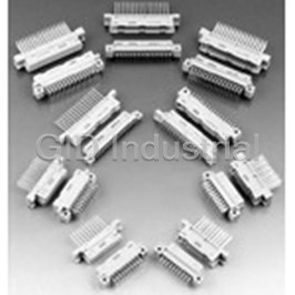
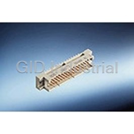
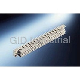
Conn Hard Metric M 80Signal/40Ground POS 2.5mm Press Fit RA Thru-Hole
973061
Part Number
973061
Price
Request Quote
Manufacturer
ERNI ELECTRONICS
Lead Time
Request Quote
Category
Connectors » Connector Backplane
Specifications
Manufacturer
ERNI Electronics
Manufacturers Part #
973061
Industry Aliases
973061
Sub-Category
Backplane Connectors
Factory Pack Quantity
64
Datasheet

Extracted Text
ERmet ZDplus - Application Note ERmet ZDplus Version 1.0 Application Note Version 2.2 www.erni.com Katalog D 074518 Ausgabe 3, 03/05 09/13 www.erni.com 1 www.erni.com 09/13 ERmet ZDplus - Application Note Version 2.2 The ERmet ZDplus connector is an enhancement of the ERmet Technical Features ZD family. This high-speed differential Hard Metric connector • Modules: 2-, 3- and 4-pair versions available. system enables data rates of 20 Gbit/s and more. • Mating: Compatible to standard ERmet ZD male connectors, The ERmet ZDplus is based on the principal mechanical design backwards compatible to existing backplane systems of the proven ERmet ZD with the same dimensions. To enable • Design: Wafers with individually fully shielded pairs of contacts. higher data rates ERNI Electronics has optimized the signal • Contacts: Low noise, dual beam, leaf contacts with one routing and the pressfit termination of the female connector. ground blade for every pair of signals. To benefit from the maximum performance of the new ERmet • Wafer pitch: 2.5 mm from wafer to wafer. ZDplus the usage of backdrilling is recommended. Decreasing • Pitch between signal pins: 1.5 mm between pairs (within wafer). via stub length and the related “stub effect” by backdrilling sig- • Pitch between pairs: 4.5 mm (within wafer). nificantly reduces the reflections and the overall BER (Bit Error • Ground arrangement: In line with signals at termination and sur- Rate) of the interconnect. rounding shield. The first product of the ERmet ZD+® family is the 4-pair right • Multiline Crosstalk: <3% at 100ps rise time, 250 mV swing. angle female connector with pressfit termination. The ERmet ZDplus female connector is mating compatible to the existing • Insertion loss: <3 dB up to 10 GHz. ERmet ZD male connector. This means, that existing backplane • Differential Impedance: 100 Ω ±5 % designs do not need layout changes on the backplane side, if • Skew Compensation: max. 3ps differential skew customers want to upgrade their systems. Of course the lay- • Power Modules: Closed entry, vertical female backplane modu- out on the daughtercards has to be modified if using the new les with stamped blades. ERmet ZDplus female parts. • Alignment Features: Improved pre-alignment guide and polari- Single pair and multi pair spice models available. Also s-parameter and zing features, 4 rigid blades for all modules. spectraquest models • Datarate Options: Female Male Datarate ZD ZD 5+ Gbit/s ZDplus ZD 15+ Gbit/s ZD ZDplus 10+ Gbit/s ZDplus ZDplus 20+ Gbit/s 3 www.erni.com 09/13 ab cd ef gh ERmet ZDplus - Application Note Version 2.2 Dimensional Drawings ERmet ZD Vertical Male Connectors 4 pair / 10 wafer 23,4 -0,1 Date Code EE-Zone für durchkontaktierte ±0.05 Löcher ø 0.6 compliant zone for through hol e ±0.05 ø 0.6 10 9 8 7 6 5 4 3 2 1 a b c d e f g h 2,5 9x2.5= 22,5 0,75 24,95 -0,1 Part Numbers Configuration Pin Version Part Number Type 4 (4 pairs) / 10 wafers D 973031 Type 4 (4 pairs) / 10 wafers B 973061 4 4 www.erni.com 09/13 1,5 4,5 5,7 0,2 () 1,7 3 -0,1 0,1 6,35 0,05 13,4 XXXXXXX ERNI ab cd ef ERmet ZDplus - Application Note Version 2.2 Dimensional Drawings ERmet ZD Vertical Male Connectors 3 pair / 10 wafer Ident-Nr. Date/Code 18,9 -0,1 EE-Zone für durchkontaktierte ±0.05 Löcher ø 0.6 compliant zone for through hol e ø 0.6 ±0.05 10 9 8 7 6 5 4 3 2 1 a b c d e f 2,5 0,75 9x2.5= 22,5 24,95 -0,1 Part Numbers Configuration Pin Version Part Number Type 3 (3 pairs) / 10 wafers D 973027 Type 3 (3 pairs) / 10 wafers B 973062 5 www.erni.com 09/13 1,5 4,5 5,7 0,2 1,7 3 -0,1 0,1 6,35 0,05 13,4 XXXXXXX ERNI 973062 ERmet ZDplus - Application Note Version 2.2 Dimensional Drawings ERmet ZDplus Vertical Male Connectors 4 pair / 10 wafer Anforderungsstufe class 23,4 -0,1 Date Code A EN-Zone für durchkontaktierte 2,5 Löcher 0.46 ± 0.05 1,5 9 x 2,5 = 22,5 compliant zone for through hole 0.46 ± 0.05 DETAIL A MAßSTAB 5 : 1 Leiterplattenoberfläche Tochterkarte Top surface of daughter card Messerkontakte sind im Paar symmetrisch angeordnet 10 9 8 7 6 5 4 3 2 1 Male contacts within pairs are arranged symmetriecally a b 1,2 GND ab c d Kontaktversionen, Messerkontakte GND cd e Contact Selection Options, Male Contacts f GND ef g AB h GND gh 2,5 9x 2,5 = 22,5 0,75 24,95 -0,1 Leiterplattenkante Backplane edge Bestückungsplan - contact layout A A A A a A A A A A A b A A A A A A A A A A GND ab Z Z Z Z Z Z Z Z Z Z c A A A A A A A A A A d A A A A A A A A A A GND cd Z Z Z Z Z Z Z Z Z Z e A A A A A A A A A A f A A A A A A A A A A GND ef Z Z Z Z Z Z Z Z Z Z g A A A A A A A A A A A h A A A A A A A A A GND gh Z Z Z Z Z Z Z Z Z Z 10 9 8 7 6 5 4 3 2 1 Part Number Configuration Pin Version Part Number Type 4 (4 pairs) / 10 wafers A 394452 6 www.erni.com 09/13 1,5 4,5 5,7 +0,2 1,6 3,8 ±0,1 5,3 ±0,1 3 -0,1 3 -0,1 6,35 ±0,1 13,4 ±0,05 XXXXXXX ERNI RC 2 ERmet ZDplus - Application Note Version 2.2 Dimensional Drawings ERmet ZDplus Vertical Male Connectors 3 pair / 10 wafer Anforderungsstufe class 18,9-0,1 Date Code A EN-Zone für durchkontaktierte 2,5 Löcher 0.46 ± 0.05 1,5 9 x 2,5 = 22,5 compliant zone for through hole 0.46 ± 0.05 DETAIL A MAßSTAB 5 : 1 Leiterplattenoberfläche Tochterkarte Messerkontakte sind im Paar symmetrisch angeordnet Top surface of daughter card Male contacts within pairs are arranged symmetriecally 10 9 84 7 6 5 3 2 1 1,2 a b Kontaktversionen, Messerkontakte GND ab c Contact Selection Options, Male Contacts d GND cd e AB f GND ef 2,5 9x 2,5 = 22,5 0,75 24,95 -0,1 Leiterplattenkante Backplane edge Bestückungsplan - contact layout a A A A A A A A A A A A A A A A A A A A b A GND ab Z Z Z Z Z Z Z Z Z Z A A A A A A A A A A c A A A A A A A A A A d Z Z Z Z Z Z Z Z Z Z GND cd A A A A A A A A A A e A f A A A A A A A A A GND ef Z Z ZZ Z Z Z Z Z Z 10 9 8 7 6 5 4 3 2 1 Part Number Configuration Pin Version Part Number Type 3 (3 pairs) / 10 wafers A 464514 7 www.erni.com 09/13 1,5 4,5 5,7 +0,2 1,6 3,8 ±0,1 5,3 ±0,1 3 -0,1 3 -0,1 6,35 ±0,1 13,4 ±0,05 XXXXXXX ERNI RC 2 ERmet ZDplus - Application Note Version 2.2 Dimensional Drawings ERmet ZDplus Vertical Male Connectors 2 pair / 10 wafer Anforderungsstufe class 15,4 -0,1 Date Code A EN-Zone für durchkontaktierte 2,5 1,5 LöcherØ 0.46 ± 0.05 9 x 2,5 = 22,5 compliant zone for through hole Ø 0.46 ± 0.05 DETAIL A MAßSTAB 5 : 1 Leiterplattenoberfläche Tochterkarte Messerkontakte sind im Paar symmetrisch angeordnet Top surface of daughter card Male contacts within pairs are arranged symmetriecally 10 9 8 7 6 5 4 3 2 1 1,2 a b GND ab c d GND cd Kontaktversionen, Messerkontakte Contact Selection Options, Male Contacts 2,5 0,75 9x 2,5 = 22,5 AB 24,95 -0,1 Leiterplattenkante Backplane edge Bestückungsplan - contact layout a A A A A A A A A A A b A A A A A A A A A A GND ab Z Z Z Z Z Z Z Z Z Z c A A A A A A A A A A d A A A A A A A A A A GND cd Z Z Z Z Z Z Z Z Z Z 10 9 8 7 6 5 4 3 2 1 Part Number Configuration Pin Version Part Number Type 2 (2 pairs) / 10 wafers A 464520 8 www.erni.com 09/13 1,5 4,5 5,7 +0,2 1,6 3,8 ±0,1 5,3 ±0,1 3 -0,1 3 -0,1 6,35 ±0,1 13,4 ±0,05 XXXXXXX ERNI RC 2 ERmet ZDplus - Application Note Version 2.2 Dimensional Drawings Right Angle Female Connectors 4 pair / 10 wafer 22,5 2,5 0,75 h g f e d c b a 10 1 EN-Zone für durchkontaktierte Löcher 0.46 ± 0.05 compliant zone for through hole 0.46 ± 0.05 15,7 24,95 -0,1 +0,2 1,6 Date Code Position GND h h g GND g GND f f e GND e GND d d c GND c GND b b a GND a 18,6 16,7 21,4 -0,1 Oberfläche der Tochterplatine Top surface of daughter card Part Numbers Configuration Part Number Type 4 (4 pairs) / 10 wafers 384312 9 www.erni.com 09/13 1,5 4,5 19,4 17,5 1,2 0,9 1,2 1,1 10,4 1 27,9 ±0,1 ERmet ZDplus - Application Note Version 2.2 Dimensional Drawings Right Angle Female Connectors 3 pair / 15 wafer Part Numbers Configuration Part Number Type 3 (3 pairs) / 15 wafers 384310 10 www.erni.com 09/13 ERmet ZDplus - Application Note Version 2.2 Dimensional Drawings Right Angle Female Connectors 3 pair / 10 wafer 9 x 2,5 = 22,5 2,5 0,75 f e d c b a 10 1 EN-Zone für durchkontaktierte Löcher 0.46 ± 0.05 compliant zone for through hole 0.46 ± 0.05 +0,2 1,6 25 max. GND f f e GND e GND d d c GND c GND b b a GND a 14,1 12,2 16,9 Oberfläche der Tochterplatine Top surface of daughter card Part Numbers Configuration Part Number Type 3 (3 pairs) / 10 wafers 454530 11 www.erni.com 09/13 1,5 4,5 14,9 13 1,2 1,2 1,1 0,9 10,4 20,2 1 23,4 ERmet ZDplus - Application Note Version 2.2 Dimensional Drawings Right Angle Female Connectors 2 pair / 10 wafer 9 x 2,5 = 22,5 2,5 0,75 d c b a 10 1 EN-Zone für durchkontaktierte +0,2 1,6 8,56 Löcher Ø 0,46 ± 0,05 compliant zone for through hole 24,95 -0,1 Ø 0,46 ± 0,05 GND d d c GND c GND b b a GND a 8,65 Oberfläche der Tochterplatine 13,35 -0,1 Top surface of daughter card Part Numbers Configuration Part Number Type 2 (2 pairs) / 10 wafers 464459 12 www.erni.com 09/13 1,5 4,5 11,35 1,2 1,2 1,1 10,4 0,9 1 18,9 ERmet ZDplus - Application Note Version 2.2 Layout Backplane Layout 4 Pair ERmet ZD Male Connector 13 www.erni.com 09/13 ERmet ZDplus - Application Note Version 2.2 Layout Backplane Layout 4 Pair ERmet ZDplus 14 www.erni.com 09/13 ERmet ZDplus - Application Note Version 2.2 Layout Daughtercard Layout 4 Pair ERmet ZDplus Female Connector Daughtercard Layout 3 Pair ERmet ZDplus Female Connector 15 www.erni.com 09/13 ERmet ZDplus - Application Note Version 2.2 Layout Daughtercard Layout 2 Pair ERmet ZDplus Female Connector Trace Routing 16 www.erni.com 09/13 ERmet ZDplus - Application Note Version 2.2 Schichtaufbau im metallisierten Loch für EN-Kontakt Plated Through-Holes for Pressfit Terminals Metal plating of plated-through hole for EN-contact Bohrungsdurchmesser des Loches All pressfit terminals of the ERmet ZDplus modules share the 0,55 ±0,02 Diameter of drilled hole Durchmesser des same plated through-hole requirements. These pressfit ter- metallisierten Loches 0,46 ±0,05 Diameter of finished minals have been used successfully with reflowed tin-lead, min. 0,05 Restringbreite plated-through hole Restring width plated tin-lead, immersion tin, organic coatings over bare copper and immersion gold hole plating regimes. The hole recommendations and press in force information shown in this catalog are for reflowed tin-lead and plated tin-lead. Additional test data for other hole plating regimes are available through customer service. max. 10 µm Sn 1) min. 25 µm Cu 1) Werden andere Oberflächentechniken, wie z.B. NiAu, chem. Sn oder Cu blank eingesetzt, sind die angegebenen Maße für Bohrungsdurchmesser, Durchmesser des metallisierten Loches, Restringbreite und die Mindestschichtdicke von Cu einzuhalten. Backdrilling Ein mögliches Überschreiten der oberen Toleranz von Maß "Durchmesser des metallisierten Loches" wird durch eine entsprechende Cu-Schichtdicke vermieden. For other platings, such as NiAu, chem. Sn or blanc Cu the recommended dimensions have to be respected for the diameter of drilled hole, diameter of plated-through hole, rest ring width and min. thickness of Cu plating. To keep the max. tolerance for the "Diameter of finished plated-through hole" the according thickness of the Cu-plating has to be used. für Einpresszone ERmet ZDplus for press-fit zone ERmet ZDplus Stubbing Effect Top connection Bottom connection The bottom connection is to prefer, because it don’t cause so much reflection. 17 www.erni.com 09/13 ERmet ZDplus - Application Note Version 2.2 High Frequency Simulation in Board Interface Simulation Setup Simulation study with traces in upper and lower layer. Two Ground Pins Cross section without insulator Description Ports Input Signal Signal rise time: 50 ps 18 www.erni.com 09/13 ERmet ZDplus - Application Note Version 2.2 High Frequency Simulation in Board Interface Results for Traces in Upper Layer Impedance NEXT of neighbored signal pairs 19 www.erni.com 09/13 ERmet ZDplus - Application Note Version 2.2 High Frequency Simulation in Board Interface FEXT of neighbored signal pairs Results for Traces in Lower Layer Impedance 20 www.erni.com 09/13 ERmet ZDplus - Application Note Version 2.2 High Frequency Simulation in Board Interface NEXT of neighbored signal pairs FEXT of neighbored signal pairs 21 www.erni.com 09/13 ERmet ZDplus - Application Note Version 2.2 Measurement Results Introduction In this abstract several results of ERNI ERmet ZDplus were presented, based on S-Parameter measurements with ZProbe. Measurement Equipment: Agilent ENA E5071C with Cascade Microtech ZProbes (GSGSG) Calibration and de-embedding were performed to isola- te the connector. Frequency Range: 300kHz...20GHz Sweep points: 3001 IF Bandwidth: 1kHz Device Under Test: ZDplus testboard V6 (20.12.2012) 22 www.erni.com 09/13 ERmet ZDplus - Application Note Version 2.2 Measurement Results Return and Insertion Loss 23 www.erni.com 09/13 ERmet ZDplus - Application Note Version 2.2 Measurement Results Crosstalk 24 www.erni.com 09/13 ERmet ZDplus - Application Note Version 2.2 Measurement Results Intra-Pair Skew 25 www.erni.com 09/13 ERmet ZDplus - Application Note Version 2.2 Guiding System Layouts Alignment pin kit with base plate Alignment pin kit without base plate Alignment guide bush kit Layout of daughter card Backplanelayout Backplanelayout Backplane 0,03 4,3 0,03 4,3 backplane daughtercard daughtercard 3,1 0,03 Ordering Information Configuration PCB Thickness Electrical Contact Part Number Guiding pin kit without base plate 2.5 - 6.0 mm Yes 214361 Guiding pin kit without base plate 6.0 - 8.0 mm Yes 214362 Guiding pin kit with base plate 2.5 - 6.0 mm Yes 214363 Guiding pin kit with base plate 6.0 - 8.0 mm Yes 214364 Guiding pin kit without base plate 2.5 - 6.0 mm No 144370 Guiding pin kit without base plate 6.0 - 8.0 mm No 144371 Guiding pin kit with base plate 2.5 - 6.0 mm No 144131 Guiding pin kit with base plate 6.0 - 8.0 mm No 144132 Guid bush kit 1.5 - 2.0 mm Yes 234675 Guid bush kit 2.0 - 4.5 mm Yes 164307 Guid bush kit 1.5 - 2.0 mm No 144127 Guid bush kit 2.0 - 4.5 mm No 144128 26 www.erni.com 09/13 +0,05 2,5 8,5 0,05 10,5 0,2 component side 10,5 0,2 15,4 3 -0,2 0,1 5,5 7 0,1 14 0,05 Member www.erni.com Katalog D 074518 Ausgabe 3, 03/05 www.erni.com 09/13 27 ERNI Electronics GmbH & Co. KG Europe South America Africa Japan Seestrasse 9 73099 Adelberg/Germany Tel +49 7166 50-0 Fax +49 7166 50-282 info@erni.de ERNI Electronics, Inc. North America Canada Mexico 2201 Westwood Ave Richmond, VA 23230/USA Tel +1 804 228-4100 Fax +1 804 228-4099 info@erni.us ERNI Asia Holding Pte Ltd. Asia Australia New Zealand Blk 4008 Ang Mo Kio Avenue 10 #04-01/02 Techplace I Singapore 569625 Tel +65 6 555 5885 Fax +65 6 555 5995 info@erni-asia.com www.erni.com © ERNI Electronics GmbH & Co. KG 2013 • Printed in Germany. A policy of continuous improvement is followed and the right to alter any published data without notice is reserved. ERNI®, MicroStac®, MicroSpeed®, MiniBridge®, MaxiBridge®, ERmet®, ERmet ZD®, ERbic® and ERNIPRESS® are trademarks (registered or applied for in various countries) of ERNI Electronics GmbH & Co. KG. AdvancedTCA®, CompactPCI® and CompactPCI Express® are trademarks of PCI Industrial Computer Manufacturers Group. 28 28 Katalog D 074518 Katalog D 074518 Ausgabe 3, 03/05 Ausgabe 3, 03/05 09/13 www.erni.com www.erni.com
Frequently asked questions
How does Electronics Finder differ from its competitors?

Is there a warranty for the 973061?
Which carrier will Electronics Finder use to ship my parts?
Can I buy parts from Electronics Finder if I am outside the USA?
Which payment methods does Electronics Finder accept?
Why buy from GID?

Quality
We are industry veterans who take pride in our work

Protection
Avoid the dangers of risky trading in the gray market

Access
Our network of suppliers is ready and at your disposal

Savings
Maintain legacy systems to prevent costly downtime

Speed
Time is of the essence, and we are respectful of yours
Related Products
Conn DIN 41612 M 48 POS 2.54mm Solder ST Thru-Hole 004484
Conn DIN 41612 M 32 POS 2.54mm Solder ST Thru-Hole 004485
Conn DIN 41612 F 30 POS 2.54mm Solder ST Thru-Hole 004492
Conn DIN 41612 M 30 POS 2.54mm Solder ST Thru-Hole 004500
Conn DIN 41612 M 32 POS Press Fit ST Thru-Hole 004502
Conn DIN 41612 F 96 POS Press Fit ST Thru-Hole 004707
Request a Quote

The quote request has been received
Close

Facing challenges or have inquiries? Feel free to contact us!
Call Us +1-469-283-2440
What they say about us
FANTASTIC RESOURCE
One of our top priorities is maintaining our business with precision, and we are constantly looking for affiliates that can help us achieve our goal. With the aid of GID Industrial, our obsolete product management has never been more efficient. They have been a great resource to our company, and have quickly become a go-to supplier on our list!
Bucher Emhart Glass
EXCELLENT SERVICE
With our strict fundamentals and high expectations, we were surprised when we came across GID Industrial and their competitive pricing. When we approached them with our issue, they were incredibly confident in being able to provide us with a seamless solution at the best price for us. GID Industrial quickly understood our needs and provided us with excellent service, as well as fully tested product to ensure what we received would be the right fit for our company.
Fuji
HARD TO FIND A BETTER PROVIDER
Our company provides services to aid in the manufacture of technological products, such as semiconductors and flat panel displays, and often searching for distributors of obsolete product we require can waste time and money. Finding GID Industrial proved to be a great asset to our company, with cost effective solutions and superior knowledge on all of their materials, it’d be hard to find a better provider of obsolete or hard to find products.
Applied Materials
CONSISTENTLY DELIVERS QUALITY SOLUTIONS
Over the years, the equipment used in our company becomes discontinued, but they’re still of great use to us and our customers. Once these products are no longer available through the manufacturer, finding a reliable, quick supplier is a necessity, and luckily for us, GID Industrial has provided the most trustworthy, quality solutions to our obsolete component needs.
Nidec Vamco
TERRIFIC RESOURCE
This company has been a terrific help to us (I work for Trican Well Service) in sourcing the Micron Ram Memory we needed for our Siemens computers. Great service! And great pricing! I know when the product is shipping and when it will arrive, all the way through the ordering process.
Trican Well Service
GO TO SOURCE
When I can't find an obsolete part, I first call GID and they'll come up with my parts every time. Great customer service and follow up as well. Scott emails me from time to time to touch base and see if we're having trouble finding something.....which is often with our 25 yr old equipment.
ConAgra Foods