

 Manufacturers
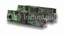
EXCELSYS XG4X03
Description
Isolated DC/DC Converters
Part Number
XG4X03
Price
Request Quote
Manufacturer
EXCELSYS
Lead Time
Request Quote
Category
Circuit Protection » AC-DC Power Supply
Specifications
Manufacturer
Excelsys
Manufacturers Part #
XG4X03
Lead Time
8 Week Lead Time
Brand
EXCELSYS
Factory Pack Quantity
1
Datasheet

Extracted Text
Xgen Product Selector The Xgen series of user configurable power supplies with its unique plug and play architecture allows system designers to define 3 and build ‘instant’ custom power solutions with industry leading 17W/in power density and up to 90% efficiency. Xgen powerPacs The application specific 4 slot and 6 slot powerPacs provide up to 12 isolated DC outputs from 200W up to 1340W. The table below summarises the powerPacs by application and power level. Please refer to the specific product datasheets for full specifications. Application Slots 200W 400W 600W 700W 750W 800W 900W 1000W 1200W 1340W Standard 4 Slot XLA XLB XLC XLD 6 Slot XCA XCB XCC XCD XCE Medical 4 Slot XMA XMB XMC XMD 6 Slot XVA XVB XVC XVD XVE Low Noise Standard 4 Slot XKA XKB XKC 6 Slot XQA XQB XQC Low Noise Medical 4 Slot XRA XRB XRC 6 Slot XZA XZB XZC Ultra Quiet Standard 4 Slot XTA XTB 6 Slot XBA XBB XBC Ultra Quiet Medical 4 Slot XNA XNB 6 Slot XWA XWB XWC Hi-Temp 6 Slot XHA XHB Xgen powerMods High Efficiency Plug and Play DC output modules to provide a wide range of DC output voltages from 1.0V up to 58.0V. Standard Xgen product options include: Conformal Coating, Low MODEL Vmin Vnom Vmax Imax Watts Vtrim Vpot Acoustic Noise, Low Leakage Current, Extra Ruggedisation, Xg1 1.0 1.5 2.5 3.6 50A 125W Connector, Cabling & Mounting options, Thermal Signals and Xg2 1.5 3.2 5.0 6.0 40A 200W Reverse Fans. See Section 4.10 for more information. Xg3 4.0 6.0 12.0 15.0 20A 240W Xg4 8.0 12.0 24.0 30.0 10A 240W Xg5 8.0 24.0 48.0 58.0 6A 288W Xg7 5.0 24.0 28.0 5A 120W Xg8 V1 5.0 24.0 28.0 3A 72W V2 5.0 24.0 28.0 3A 72W www.excelsys.com 2 Contents CoNTENTS Section 1 Introduction Section 1.1 ...........About Excelsys ................................................................................................................................04 Section 1.2 ...........Xgen overview ..................................................................................................................................05 Section 2 Product Datasheets 4 Slot 200W-750W .........Standard ...........................XL ...........................................................................................................06 200W-750W .........Medical .............................XM ............................................................................................................08 200W-600W .........Low Noise Standard .........XK ............................................................................................................10 200W-600W .........Low Noise Medical ...........XR ............................................................................................................12 200W-400W .........Ultra Quiet Standard.........XT ............................................................................................................14 200W-400W .........Ultra Quiet Medical...........XN ............................................................................................................16 6 Slot 400W-1340W .......Standard ...........................XC ............................................................................................................18 400W-1340W .......Medical .............................XV.............................................................................................................20 400W-1200W .......Low Noise Standard .........XQ ...........................................................................................................22 400W-1200W .......Low Noise Medical ...........XZ ............................................................................................................24 400W-800W .........Ultra Quiet Standard.........XB ............................................................................................................26 400W-800W .........Ultra Quiet Medical...........XW ...........................................................................................................28 400W-600W .........Hi-Temp ............................XH.............................................................................................................30 Section 3 Getting started with your Xgen Section 3.1 ...........Configuring your Xgen ......................................................................................................................32 Section 3.2 ...........Additional Xgen Flexibility and Signals .............................................................................................32 Section 3.3 ...........Connectors ........................................................................................................................................33 Section 3.4 ...........Mechanical Drawings ........................................................................................................................34 Section 3.5 ...........Configuration Examples ....................................................................................................................38 Section 4 Xgen Designer Manual Section 4.1 ...........overview of the Xgen Series ............................................................................................................40 Section 4.2 ...........Installation Considerations ................................................................................................................40 Section 4.3 ...........Xgen Mounting Considerations .........................................................................................................40 Section 4.4 ...........Theory of operation ..........................................................................................................................41 Section 4.5 ...........Xgen Configuration ...........................................................................................................................41 Section 4.6 ...........PowerMod operation ........................................................................................................................42 Section 4.7 ...........PowerMod Signals ............................................................................................................................47 Section 4.8 ...........PowerPac operation .........................................................................................................................47 Section 4.9 ...........PowerPac (Global) Signals ...............................................................................................................48 Section 4.10 .........PowerPac options ............................................................................................................................49 Section 4.11 .........Power Ratings ...................................................................................................................................49 Section 4.12 .........Reliability ...........................................................................................................................................51 Section 4.13 .........Safety ................................................................................................................................................52 Section 4.14 .........EMC ..................................................................................................................................................53 Section 5 Technical Resources Section 5.1 ...........Consult an Engineer and online Resources ...................................................................................54 Section 5.2 ...........Xgen Configurator and Product Selector ...........................................................................................55 www.excelsys.com 3 about About Excelsys Section 1.1 about Excelsys your Global Partner for Mission critical Modular Power Supplies Excelsys Technologies brings over 20 years experience of modular power supply development and applications support in our revolutionary Xgen series of products. We serve original equipment manufacturers globally from our head office in Ireland, our additional sales offices in USA and China and our network of qualified and experienced distributors in over 30 countries worldwide. Together we have established Excelsys as the brand of choice for customers seeking the highest performing, most reliable and most cost efficient modular power solutions available in the market. Serving your Markets, Delivering your Solutions... Whatever your application, our dedicated teams of Sales and Applications Engineers are ready to assist you in defining and implementing the optimum modular power solution to meet your custom requirements. Some of the industries where Excelsys have demonstrated success include: MEDIcaL Medical power supply design and manufacturing demands the highest safety and quality standards. The medically certified solutions in the Xgen Platform are the solutions of choice for variety of applications including: clinical Diagnostic Equipment ● Medical Lasers ● X-ray Machines ● cT-Scanners ● MRI Scanners Dialysis Equipment ● Skin Treatment and Regeneration ● cryotherapy Equipment ● cancer Treatment Equipment INDUSTRIaL Excelsys Technologies designs and manufactures power supplies that meet the rigorous demands of the industrial sector. our products are ideal for a variety of industrial, automation and test & measurement applications including: Industrial Lasers ● Optical Inspection Equipment ● Electronic Microscopes ● Printer & Paper Binder Equipment ● Wafer Fabrication ● High-End camera Equipment ● Industrial cutting Equipment cOMMUNIcaTIONS The Xgen range of modular power supplies meet the high reliability and stringent space requirements (1U) of the communications electronics sector and are used across a wide number of applications including: Wireless Telephony Equipment ● Bulk Power System ● Base Stations ● Data communications MILITaRy Excelsys designs and manufactures CoTS (Commercial off The Shelf) power supplies that meet the high reliability and often harsh operating environments of the military electronics industry and are ideal for use in a variety of applications including: Radar Systems ● Data acquisition (Ground Based and Mobile) ● communications Equipment Test & Measurement Equipment Excelsys: Our commitment to you... As a global supplier of modular power supplies, Excelsys combines the latest technology, management methods and a total customer service philosophy to provide the best performing and highest reliability solutions for your business. Working closely with both our customers and channel partners we are committed to ensuring our products provide the lowest total cost of power supply ownership over the life of your system. www.excelsys.com 4 Overview overview of the Xgen Series Section 1.2 Overview The Xgen series brings oEM power supplies to a new paradigm, combining technical excellence with logistics simplicity to provide the world's most flexible, high efficiency, high reliability modular power supply. Xgen continues the Excelsys tradition of providing an instant, no compromise power solution for any application where a unique set of voltage and current requirements is needed. The Xgen power supply is the most flexible modular power supply in the world. This power supply family ranges in power from 200W to 1340W and is used throughout various industries including Medical, Industrial, Communications and Military. Need a custom power supply in a hurry? Xgen is a true Plug & Play multiple-output power supply. Any one of more than 30 million cUSTOM POWER configurations can be assembled anywhere, in under 5 minutes, from standard, volume-produced modules. This is the new-paradigm: a custom power supply available in 5 minutes from standard parts. Too much heat generated in your equipment? Difficult to maintain your equipment at the right temperature? Xgen has industry unrivalled efficiency, exceeding 90%. This means that less than half of the amount EFFIcIENcy of waste heat is created in comparison to conventional multiple output power sources with efficiencies of 80% and lower. It also guarantees increased system reliability. Not enough space available in your equipment? Is space at a premium, making design and manufacture difficult and compromised? 3 Xgen has industry unrivalled power density for a full functionality AC/DC power supply, at 17W/in . SPacE You can get 1340W of multiple-output power source in 1U rack space. Its high power density minimises weight and maximises available space in your design for other components and general accessibility. Looking for a cost-effective long term solution for all your power supply requirements? cOST-EFFEcTIVE Xgen is configured from standard subassemblies that are manufactured in volume in our world class manufacturing facility. This allows Excelsys to provide you with all the benefits of Xgen at a world class competitive price. Contact Excelsys or one of our distributors for details. Worried about meeting all relevant standards - EMc, Safety, etc? Xgen series models are fully compliant with all relevant standards. Standard parts meets the STaNDaRD requirements EN60950, UL60950, CSA22.2, EN61000-3-x and EN61000-4-x. Additionally our aPPROVaLS medically approved range meet the requirements of EN60601 and UL60601 3rd edition for medical applications. www.excelsys.com 5 J1 J2 INPUT AC 100V-240V 50/60Hz SEE INSTRUCTION MANUAL 70C MAX OPERATING TEMPERATURE J1 J2 INPUT AC 100V-240V 50/60Hz SEE INSTRUCTION MANUAL 70C MAX OPERATING TEMPERATURE Standard 200W-750W L Slimline Power Supply User Configurable 1U Size Series The XL family of power supplies provides up to 750W in a slimline 1U package. tPLUG & PLay POWER Providing up to 8 isolated outputs, the XL family is the most flexible power supply next generation power solution in its class and brings affordable configurable power to the 200-750W market. FEaTURES & OPTIONS The slimline product boasts unrivalled power density saving valuable system space. • Ultra high efficiency, up to 89% Combined with ultra high efficiencies, the XL family provides system designers with • Extra low profile: 1U height (40mm) flexible instant solutions that significantly shorten design-in time and simplify integration. • Plug & Play Power - allows fast custom configuration The XL family consists of 4 powerPac models in 200W, 400W, 600W and 750W power • Individual output control signals levels. Each powerPac model may be populated with up to 4 powerMods selected from • All outputs fully floating the table of powerMods shown below. • Series / Parallel of multiple outputs • Few electrolytic capacitors (all long life) All configurations carry full safety agency approvals, UL60950, EN60950 and are CE • Visual LED indicators marked. • 5V bias standby voltage provided • Standard Xgen product options include: powerMods powerPacs Conformal Coating, Low Acoustic Noise, MODEL Watts MODEL Vmin Vnom Vmax Imax Watts Low Leakage Current, Extra Ruggedisation, Vtrim Vpot XLA 200W Connector, Cabling & Mounting options, Xg1 1.0 1.5 2.5 3.6 50A 125W XLB 400W Thermal Signals and Reverse Fans. See Xg2 1.5 3.2 5.0 6.0 40A 200W Section 4.10 for more information XLC 600W Xg3 4.0 6.0 12.0 15.0 20A 240W XLD 750W aPPLIcaTIONS INcLUDE Xg4 8.0 12.0 24.0 30.0 10A 240W • Industrial machines Xg5 8.0 24.0 48.0 58.0 6A 288W • Test and measurement Xg7 5.0 24.0 28.0 5A 120W • Automation equipment Xg8 V1 5.0 24.0 28.0 3A 72W • Printing V2 5.0 24.0 28.0 3A 72W • Telecommunications • For Medical applications see Xmite MEcHaNIcaL SPEcIFIcaTIONS Note: See diagrams on pages 34-37 XLa, XLB, XLc XLD Third angle projection Third angle projection 50.00 97.75 54.00 97.75 46.00 122.00 92.00 122.00 92.00 23.50 23.50 SLOT D SLOT D SLOT C SLOT C 19.00 89.00 19.00 89.00 42.00 TOP VIEW 42.00 TOP VIEW SLOT B SLOT B SLOT A SLOT A 23.50 23.50 40.40 40.40 29.50 29.50 All dimensions in mm. All dimensions in mm. Mounting Holes Mounting Holes 4 M4 threaded holes on Base. Max screw penetration is 6mm from Base. 4 M4 threaded holes on Base. Max screw penetration is 6mm from Base. Fleximount Side Mounting Slots Fleximount Side Mounting Slots Use with self-clinching studs type FH-M4-X or FH-832-X (X= stud length) from PEM, or equivalent Use with self-clinching studs type FH-M4-X or FH-832-X (X= stud length) from PEM, or equivalent Alternatively, use Xgen Side Clamps from Excelsys. Part No. Z165 (drawing 61401) Alternatively, use Xgen Side Clamps from Excelsys. Part No. Z165 (drawing 61401) www.excelsys.com 6 XL Standard 200W-750W SPEcIFIcaTION applies to configured units consisting of powerMods inserted into the appropriate powerPac INPUT Parameter conditions/Description Min Nom Max Units Input Voltage Range Universal Input 47-63Hz. Contact factory for 440Hz operation 85 264 VAC 120 380 VDC Power Rating XLA:200W, XLB:400W, XLC:600W, XLD:750W See Section 4.11 for line voltage deratings Input current XLA 85VAC in 200W out 4.0 A XLB 85VAC in 400W out 6.0 A XLC 85VAC in 400W out 7.5 A XLD 85VAC in 525W out 7.5 A Inrush current 230VAC, 25°C 50 A Undervoltage Lockout Shutdown 65 74 VAC Fusing XLA 250V 5 x 20mm F5A HRC XLB 250V 5 x 20mm F6.3A HRC XLC, XLD 250V 5 x 20mm F8A HRC OUTPUT Parameter conditions/Description Min Nom Max Units powerMod Power As per powerMod table Output adjustment Range Manual: Multi-turn potentiometer. As per powerMod table Electronic: See Section 4.6 Minimum Load 0A Line Regulation For ±10% change from nominal line ±0.1 % Load Regulation For 25% to 75% load change ±0.2 % cross Regulation ±0.2 % Transient Response For 25% to 75% load change Voltage Deviation 10 % Settling Time 250 µs Ripple and Noise 20MHz 100mV or 1.0% pk-pk Overvoltage Protection 1st level: Vset Tracking. 2nd level: Vmax (Latching) 110 125 % Overcurrent Protection Straight line with hiccup activation at <30% of Vnom 110 120 % See Section 4.6 Remote Sense Max. line drop compensation. (except Xg7, Xg8) 0.5 VDC Overshoot 2% Turn-on Delay From AC In / Enable signal XLA, XLB, XLC 600 / 30 ms From AC In / Enable signal XLD 1000/30 ms Rise Time Monotonic 5 ms Hold-up Time For nominal output voltages at full load XLA, XLB, XLC/XLD 20/15 ms Output Isolation output to output / output to Chassis 500 / 500 VDC GENERaL Parameter conditions/Description Min Nom Max Units Isolation Voltage Input to output 3000 VAC Input to Chassis 1500 VAC Efficiency 230VAC, 750W @ 24V 89 % Safety agency approvals EN60950, UL60950, CSA22.2 No.950 UL File No. E181875 Leakage current 250VAC, 60Hz, 25°C 1.5 mA Signals See Section 4.9 Bias Supply Always on. Current 250mA. 500mA option available 4.8 5.0 5.2 VDC Reliability Failures per million hours at 25°C and full load powerMod 0.98 fpmh See Section 4.12. powerPac excludes fans powerPac 0.92 fpmh EMc Parameter Standard Level Units Emissions conducted EN55011, EN55022, FCC Level B Radiated EN55011, EN55022, FCC Level B Harmonic Distortion EN61000-3-2 Class A Compliant Flicker & Fluctuation EN61000-3-3 Compliant Immunity Electrostatic Discharge EN61000-4-2 Level 2 Radiated Immunity EN61000-4-3 Level 3 Fast Transients-Burst EN61000-4-4 Level 3 Input Line Surges EN61000-4-5 Level 3 conducted Immunity EN61000-4-6 Level 3 Voltage Dips EN61000-4-11 Compliant ENVIRONMENTaL Parameter conditions/Description Min Nom Max Units Operating Temperature -20 +70 °C Storage Temperature -40 +85 °C Derating See Section 4.11 for full temperature deratings Relative Humidity Non-condensing 5 95 %RH Shock 3000 Bumps, 10G (16ms) half sine Vibration 1.5G 10 200 Hz NOTES 1. This product is not intended for use as a stand alone unit and must be installed by qualified personnel. 2. The specifications contained herein are believed to be correct at time of publication and are subject to change without notice. 3. All specifications at nominal input, full load, 25°C unless otherwise stated. 4. XLD: 800W peak for 1s; Duty cycle 7%. powerMod output power must not exceed normal ratings. 5. When powering inductive or capacitive loads, it is recommended to use a blocking diode on the output. 6. Conformal Coating option: See Sections 3.1 and 4.10 for details. 7. For section references above go to the Xgen Designers Manual. www.excelsys.com 7 J1 J2 INPUT AC 100V-240V 50/60Hz SEE INSTRUCTION MANUAL 70C MAX OPERATING TEMPERATURE J1 J2 INPUT AC 100V-240V 50/60Hz SEE INSTRUCTION MANUAL 70C MAX OPERATING TEMPERATURE Slimline Medical 200W-750W M Medical Power Supply User Configurable 1U size Series The XM family of medically approved power supplies provides up to 750W in a PLUG & PLay POWER slimline 1U package. The XM family carries the latest safety agency approvals next generation power solution to EN60601-1 and UL60601-1 3rd Edition, meeting the stringent creepage and clearance requirements in this compact package. Providing up to 8 isolated FEaTURES & OPTIONS outputs, the XM family is the most flexible power supply in its class and brings • EN60601-1 3rd edition approved affordable configurable power to the 200-750W medical market. • Less than 300μA leakage current • 150µA option available The XM family consists of 4 powerPac models in 200W, 400W, 600W and 750W power • 4000VAC isolation levels. Each powerPac model may be populated with up to 4 powerMods selected from • Ultra high efficiency, up to 89% the table of powerMods shown below. Simply select your appropriate powerPac and • Extra low profile: 1U height (40mm) powerMods to get your instant custom power solution. • Plug & Play Power - allows fast custom configuration This slimline product boasts unrivalled power density, providing significant system space • Individual output control signals savings. Combined with ultra-high efficiencies, the XM family provides system designers • All outputs fully floating with flexible instant solutions that significantly shorten system design-in time. • Series / Parallel of multiple outputs • Few electrolytic capacitors (all long life) • 5V bias standby voltage provided powerMods powerPacs • Standard Xgen product options include: Conformal Coating, Low Acoustic Noise, MODEL Watts MODEL Vmin Vnom Vmax Imax Watts Low Leakage Current, Extra Ruggedisation, Vtrim Vpot XMA 200W Connector, Cabling & Mounting options, Xg1 1.0 1.5 2.5 3.6 50A 125W XMB 400W Thermal Signals and Reverse Fans. See Xg2 1.5 3.2 5.0 6.0 40A 200W XMC 600W Section 4.10 for more information Xg3 4.0 6.0 12.0 15.0 20A 240W XMD 750W Xg4 8.0 12.0 24.0 30.0 10A 240W aPPLIcaTIONS INcLUDE Xg5 8.0 24.0 48.0 58.0 6A 288W • Radiological imaging • Clinical diagnostics Xg7 5.0 24.0 28.0 5A 120W • Medical lasers Xg8 V1 5.0 24.0 28.0 3A 72W • Clinical chemistry V2 5.0 24.0 28.0 3A 72W MEcHaNIcaL SPEcIFIcaTIONS Note: See diagrams on pages 34-37 XMa, XMB, XMc XMD Third angle projection Third angle projection 50.00 97.75 54.00 97.75 46.00 122.00 92.00 122.00 92.00 23.50 23.50 SLOT D SLOT D SLOT C SLOT C 19.00 89.00 42.00 TOP VIEW 19.00 89.00 42.00 TOP VIEW SLOT B SLOT B SLOT A SLOT A 23.50 23.50 40.40 40.40 29.50 29.50 All dimensions in mm. All dimensions in mm. Mounting Holes Mounting Holes 4 M4 threaded holes on Base. Max screw penetration is 6mm from Base. 4 M4 threaded holes on Base. Max screw penetration is 6mm from Base. Fleximount Side Mounting Slots Fleximount Side Mounting Slots Use with self-clinching studs type FH-M4-X or FH-832-X (X= stud length) from PEM, or equivalent Use with self-clinching studs type FH-M4-X or FH-832-X (X= stud length) from PEM, or equivalent Alternatively, use Xgen Side Clamps from Excelsys. Part No. Z165 (drawing 61401) Alternatively, use Xgen Side Clamps from Excelsys. Part No. Z165 (drawing 61401) www.excelsys.com 8 XM Slimline Medical 200W-750W SPEcIFIcaTION applies to configured units consisting of powerMods plugged into the appropriate powerPac INPUT Parameter conditions/Description Min Nom Max Units Input Voltage Range Universal Input 47-63Hz. Contact factory for 440Hz operation 85 264 VAC 120 380 VDC Power Rating XMA:200W, XMB:400W, XMC:600W, XMD:750W See Section 4.11 for line voltage deratings Input current XMA 85VAC in 200W out 4.0 A XMB 85VAC in 400W out 6.0 A XMC 85VAC in 400W out 7.5 A XMD 85VAC in 525W out 7.5 A Inrush current 230VAC, 25°C 50 A Undervoltage Lockout Shutdown 65 74 VAC Fusing XMA 250V 5 x 20mm F5A HRC XMB 250V 5 x 20mm F6.3A HRC XMC, XMD 250V 5 x 20mm F8A HRC OUTPUT Parameter conditions/Description Min Nom Max Units powerMod Power As per powerMod table Output adjustment Range Manual: Multi-turn potentiometer. As per powerMod table Electronic: See Section 4.6 Minimum Load 0A Line Regulation For ±10% change from nominal line ±0.1 % Load Regulation For 25% to 75% load change ±0.2 % cross Regulation ±0.2 % Transient Response For 25% to 75% load change Voltage Deviation 10 % Settling Time 250 µs Ripple and Noise 20MHz 100mV or 1.0% pk-pk Overvoltage Protection 1st level: Vset Tracking. 2nd level: Vmax (Latching) 110 125 % Overcurrent Protection Straight line with hiccup activation at <30% of Vnom 110 120 % See Section 4.6 Remote Sense Max. line drop compensation. (except Xg7, Xg8) 0.5 VDC Overshoot 2% Turn-on Delay From AC In / Enable signal XMA, XMB, XMC 600 / 30 ms From AC In / Enable signal XMD 1000/30 ms Rise Time Monotonic 5 ms Hold-up Time For nominal output voltages at full load XMA,XMB, XMC/XMD 20/15 ms Output Isolation output to output / output to Chassis 500 / 500 VDC GENERaL Parameter conditions/Description Min Nom Max Units Isolation Voltage Input to output 4000 VAC Input to Chassis 1500 VAC Efficiency 230VAC, 750W @ 24V 89 % Safety agency approvals EN60601-1, UL60601-1 3rd Edition, CSA601-1 UL File no. E230761 Leakage current 250VAC, 60Hz, 25°C 300 µA 250VAC, 60Hz, 25°C option 04 150 µA Signals See Section 4.9 Bias Supply Always on. Current 250mA. 500mA option available 4.8 5.0 5.2 VDC Reliability Failures per million hours at 25°C and full load powerMod 0.98 fpmh See Section 4.12. powerPac excludes fans powerPac 0.92 fpmh EMc Parameter Standard Level Units Emissions conducted EN55011, EN55022, FCC Level B Radiated EN55011, EN55022, FCC Level B Harmonic Distortion EN61000-3-2 Class A Compliant Flicker & Fluctuation EN61000-3-3 Compliant Immunity Electrostatic Discharge EN61000-4-2 Level 2 Radiated Immunity EN61000-4-3 Level 3 Fast Transients-Burst EN61000-4-4 Level 3 Input Line Surges EN61000-4-5 Level 3 conducted Immunity EN61000-4-6 Level 3 Voltage Dips EN61000-4-11 Compliant ENVIRONMENTaL Parameter conditions/Description Min Nom Max Units Operating Temperature -20 +70 °C Storage Temperature -40 +85 °C Derating See Section 4.11 for full temperature deratings Relative Humidity Non-condensing 5 95 %RH Shock 3000 Bumps, 10G (16ms) half sine Vibration 1.5G 10 200 Hz NOTES 1. This product is not intended for use as a stand alone unit and must be installed by qualified personnel. 2. The specifications contained herein are believed to be correct at time of publication and are subject to change without notice. 3. All specifications at nominal input, full load, 25°C unless otherwise stated. 4. XMD: 800W peak for 1s; Duty cycle 7%. powerMod output power must not exceed normal ratings. 5. When powering inductive or capacitive loads, it is recommended to use a blocking diode on the output. 6. For section references above go to the Xgen Designers Manual. www.excelsys.com 9 J1 J2 INPUT AC 100V-240V 50/60Hz SEE INSTRUCTION MANUAL 70C MAX OPERATING TEMPERATURE Low acoustic Noise 200W-600W K Slimline Power Supply User Configurable 1U size Series The XK family of low acoustic noise power supplies provides up to 600W in a PLUG & PLay POWER slimline 1U x 260mm x 89mm package. Providing up to 8 isolated outputs, the next generation power solution XK family is the most flexible power supply in its class and brings affordable configurable power to the 200-600W market. FEaTURES & OPTIONS • Low Acoustic noise 39.8dBA Ideal for acoustic sensitive applications, the XK boasts unrivalled power density • Ultra high efficiency, up to 89% saving valuable system space. Combine with ultra high efficiencies, the XK family • Extra low profile: 1U height (40mm) provides system designers with flexible instant solutions that significantly shorten and • Plug & Play Power - allows fast custom simplify system design-in time. configuration The XK family consists of 3 powerPac models in 200W, 400W and 600W power levels. • Individual output control signals Each powerPac model may be populated with up to 4 powerMods selected from the • All outputs fully floating table of powerMods shown below. • Series / Parallel of multiple outputs • Few electrolytic capacitors (all long life) All configurations carry full safety agency approvals, UL60950, EN60950 and are CE • Visual LED indicators marked. • 5V bias standby voltage provided powerMods powerPacs • Standard Xgen product options include: Conformal Coating, Low Acoustic Noise, MODEL Watts MODEL Vmin Vnom Vmax Imax Watts Low Leakage Current, Extra Ruggedisation, Vtrim Vpot XKA 200W Connector, Cabling & Mounting options, Xg1 1.0 1.5 2.5 3.6 50A 125W XKB 400W Thermal Signals and Reverse Fans. See Xg2 1.5 3.2 5.0 6.0 40A 200W XKC 600W Section 4.10 for more information Xg3 4.0 6.0 12.0 15.0 20A 240W aPPLIcaTIONS INcLUDE Xg4 8.0 12.0 24.0 30.0 10A 240W • Audio Equipment Xg5 8.0 24.0 48.0 58.0 6A 288W • Test and measurement Xg7 5.0 24.0 28.0 5A 120W • Telecommunications Xg8 V1 5.0 24.0 28.0 3A 72W • For Medical applications see Xmite V2 5.0 24.0 28.0 3A 72W Note: See diagrams on pages 34-37 EFFIcIENcy (typical) MEcHaNIcaL SPEcIFIcaTIONS 93 92 Third angle projection 91 50.00 97.75 90 46.00 122.00 92.00 89 88 23.50 SLOT D 87 SLOT C 86 19.00 89.00 42.00 TOP VIEW 85 SLOT B 84 SLOT A 23.50 70 85 100 115 130 145 160 175 190 205 220 235 260 Line Voltage VAC 40.40 29.50 All dimensions in mm. M www.excelsys.com 10 Efficiency % XK Low acoustic Noise 200W-600W SPEcIFIcaTION applies to configured units consisting of powerMods plugged into the appropriate powerPac INPUT Parameter conditions/Description Min Nom Max Units Input Voltage Range Universal Input 47-63Hz. Contact factory for 440Hz operation 85 264 VAC 120 380 VDC Power Rating XKA:200W, XKB:400W, XKC:600W See Section 4.11 for line voltage deratings Input current XKA 85VAC in 200W out 4.5 A XKB 85VAC in 400W out 5.5 A XKC 85VAC in 400W out 7.5 A Inrush current 230VAC, 25°C 50 A Undervoltage Lockout Shutdown 65 74 VAC Fusing XKA 250V 5 x 20mm F5A HRC XKB 250V 5 x 20mm F6.3A HRC XKC 250V 5 x 20mm F8A HRC OUTPUT Parameter conditions/Description Min Nom Max Units powerMod Power As per powerMod table Output adjustment Range Manual: Multi-turn potentiometer. As per powerMod table Electronic: See Section 4.6 Minimum Load 0A Line Regulation For ±10% change from nominal line ±0.1 % Load Regulation For 25% to 75% load change ±0.2 % cross Regulation ±0.2 % Transient Response For 25% to 75% load change Voltage Deviation 10 % Settling Time 250 µs Ripple and Noise 20MHz 100mV or 1.0% pk-pk Overvoltage Protection Two-level. 1st level: Vset Tracking. 2nd level: Vmax (Latching) 110 125 % Overcurrent Protection Straight line with hiccup activation at <30% of Vnom 110 120 % See Section 4.6 Remote Sense Max. line drop compensation. (except Xg7, Xg8) 0.5 VDC Overshoot 2% Turn-on Delay From AC In / Enable signal 600 / 30 ms Rise Time Monotonic 5 ms Hold-up Time For nominal output voltages at full load 20 ms Output Isolation output to output / output to Chassis 500 / 500 VDC GENERaL Parameter conditions/Description Min Nom Max Units Isolation Voltage Input to output 3000 VAC Input to Chassis 1500 VAC Efficiency 230VAC, 600W @ 24V 89 % Safety agency approvals EN60950, UL60950, CSA22.2 No.950 UL File No. E181875 Leakage current 250VAC, 60Hz, 25°C 1.5 mA Signals See Section 4.9 Bias Supply Always on. Current 250mA. 500mA option available 4.8 5.0 5.2 VDC Reliability Failures per million hours at 25°C and full load powerMod 0.98 fpmh See Section 4.12. powerPac excludes fans powerPac 0.92 fpmh EMc Parameter Standard Level Units Emissions conducted EN55011, EN55022, FCC Level B Radiated EN55011, EN55022, FCC Level B Harmonic Distortion EN61000-3-2 Class A Compliant Flicker & Fluctuation EN61000-3-3 Compliant Immunity Electrostatic Discharge EN61000-4-2 Level 2 Radiated Immunity EN61000-4-3 Level 3 Fast Transients-Burst EN61000-4-4 Level 3 Input Line Surges EN61000-4-5 Level 3 conducted Immunity EN61000-4-6 Level 3 Voltage Dips EN61000-4-11 Compliant ENVIRONMENTaL Parameter conditions/Description Min Nom Max Units Operating Temperature -20 +70 °C Storage Temperature -40 +85 °C Derating See Section 4.11 for full temperature deratings Relative Humidity Non-condensing 5 95 %RH acoustic Noise Measured from distance of 1m 39.8 dBA Shock 3000 Bumps, 10G (16ms) half sine Vibration 1.5G 10 200 Hz NOTES 1. This product is not intended for use as a stand alone unit and must be installed by qualified personnel. 2. The specifications contained herein are believed to be correct at time of publication and are subject to change without notice. 3. All specifications at nominal input, full load, 25°C unless otherwise stated. 4. When powering inductive or capacitive loads, it is recommended to use a blocking diode on the output. 5. Conformal Coating option: See Sections 3.1 and 4.10 for details. 6. For section references above go to the Xgen Designers Manual. www.excelsys.com 11 J1 J2 INPUT AC 100V-240V 50/60Hz SEE INSTRUCTION MANUAL 70C MAX OPERATING TEMPERATURE Low acoustic Noise Medical 200W-600W R Medical Power Supply Low Acoustic Noise 1U size Series The XR family of low acoustic noise medically approved power supplies PLUG & PLay POWER provides up to 600W in a slimline 1u x 260mm x 89mm package. Ideal for next generation power solution acoustic sensitive medical equipment, the XR family carries full safety agency approvals to EN60601-1 and UL60601-1 3rd Edition, meeting the stringent FEaTURES & OPTIONS creepage and clearance requirements in this compact package. Providing up to • Low Acoustic noise 39.8dBA 8 isolated outputs, the XR family is the most flexible power supply in its class • EN60601-1 3rd edition approved and brings affordable configurable power to the 200-600W medical market. • Less than 300μA leakage current • 150µA option available The XR family consists of 3 powerPac models in 200W, 400W and 600W power levels. • 4000VAC isolation Each powerPac model may be populated with up to 4 powerMods selected from the table of powerMods shown below. Simply select your appropriate powerPac and powerMods • Ultra high efficiency, up to 89% to get your instant custom power solution. • Extra low profile: 1U height (40mm) • Plug & Play Power - allows fast custom This slimline product boasts unrivalled power density, providing significant system space configuration savings. Combined with ultra-high efficiencies, the XR family provides system designers • Individual output control signals with flexible instant solutions that significantly shorten system design-in time. • All outputs fully floating • Series / Parallel of multiple outputs powerMods powerPacs • Few electrolytic capacitors (all long life) MODEL Watts MODEL Vmin Vnom Vmax Imax Watts • 5V bias standby voltage provided Vtrim Vpot XRA 200W • Standard Xgen product options include: Xg1 1.0 1.5 2.5 3.6 50A 125W Conformal Coating, Low Acoustic Noise, XRB 400W Low Leakage Current, Extra Ruggedisation, Xg2 1.5 3.2 5.0 6.0 40A 200W XRC 600W Connector, Cabling & Mounting options, Xg3 4.0 6.0 12.0 15.0 20A 240W Thermal Signals and Reverse Fans. See Xg4 8.0 12.0 24.0 30.0 10A 240W Section 4.10 for more information Xg5 8.0 24.0 48.0 58.0 6A 288W Xg7 5.0 24.0 28.0 5A 120W aPPLIcaTIONS INcLUDE • Radiological imaging Xg8 V1 5.0 24.0 28.0 3A 72W V2 5.0 24.0 28.0 3A 72W • Clinical diagnostics • Medical lasers Note: See diagrams on pages 34-37 MEcHaNIcaL SPEcIFIcaTIONS • Clinical chemistry Third angle projection 50.00 97.75 46.00 122.00 92.00 EFFIcIENcy (typical) 23.50 SLOT D SLOT C 19.00 89.00 42.00 TOP VIEW 93 SLOT B 92 SLOT A 91 23.50 90 89 88 87 86 85 84 40.40 29.50 190 205 70 85 100 115 130 145 160 175 220 235 260 Line Voltage VAC All dimensions in mm. M www.excelsys.com 12 Efficiency % XR Low acoustic Noise Medical 200W-600W SPEcIFIcaTION applies to configured units consisting of powerMods plugged into the appropriate powerPac INPUT Parameter conditions/Description Min Nom Max Units Input Voltage Range Universal Input 47-63Hz. Contact factory for 440Hz operation 85 264 VAC 120 380 VDC Power Rating XRA:200W, XRB:400W, XRC:600W See Section 4.11 for line voltage deratings Input current XRA 85VAC in 200W out 4.5 A XRB 85VAC in 400W out 5.5 A XRC 85VAC in 400W out 7.5 A Inrush current 230VAC, 25°C 50 A Undervoltage Lockout Shutdown 65 74 VAC Fusing XRA 250V 5 x 20mm F5A HRC XRB 250V 5 x 20mm F6.3A HRC XRC 250V 5 x 20mm F8A HRC OUTPUT Parameter conditions/Description Min Nom Max Units powerMod Power As per powerMod table Output adjustment Range Manual: Multi-turn potentiometer. As per powerMod table Electronic: See Section 4.6 Minimum Load 0A Line Regulation For ±10% change from nominal line ±0.1 % Load Regulation For 25% to 75% load change ±0.2 % cross Regulation ±0.2 % Transient Response For 25% to 75% load change Voltage Deviation 10 % Settling Time 250 µs Ripple and Noise 20MHz 100mV or 1.0% pk-pk Overvoltage Protection 1st level: Vset Tracking. 2nd level: Vmax (Latching) 110 125 % Overcurrent Protection Straight line with hiccup activation at <30% of Vnom 110 120 % See Section 4.6 Remote Sense Max. line drop compensation. (except Xg7, Xg8) 0.5 VDC Overshoot 2% Turn-on Delay From AC In / Enable signal 600 / 30 ms Rise Time Monotonic 5 ms Hold-up Time For nominal output voltages at full load 20 ms Output Isolation output to output / output to Chassis 500 / 500 VDC GENERaL Parameter conditions/Description Min Nom Max Units Isolation Voltage Input to output 4000 VAC Input to Chassis 1500 VAC Efficiency 230VAC, 600W @ 24V 89 % Safety agency approvals EN60601-1, UL2601-1, CSA601-1 UL File No. E230761 Leakage current 250VAC, 60Hz, 25°C 300 µA 250VAC, 60Hz, 25°C option 04 150 μA Signals See Section 4.9 Bias Supply Always on. Current 250mA. 500mA option available 4.8 5.0 5.2 VDC Reliability Failures per million hours at 25°C and full load powerMod 0.98 fpmh See Section 4.12. powerPac excludes fans powerPac 0.92 fpmh EMc Parameter Standard Level Units Emissions conducted EN55011, EN55022, FCC Level B Radiated EN55011, EN55022, FCC Level B Harmonic Distortion EN61000-3-2 Class A Compliant Flicker & Fluctuation EN61000-3-3 Compliant Immunity Electrostatic Discharge EN61000-4-2 Level 2 Radiated Immunity EN61000-4-3 Level 3 Fast Transients-Burst EN61000-4-4 Level 3 Input Line Surges EN61000-4-5 Level 3 conducted Immunity EN61000-4-6 Level 3 Voltage Dips EN61000-4-11 Compliant ENVIRONMENTaL Parameter conditions/Description Min Nom Max Units Operating Temperature -20 +70 °C Storage Temperature -40 +85 °C Derating See Section 4.11 for full temperature deratings Relative Humidity Non-condensing 5 95 %RH acoustic Noise Measured from distance of 1m 39.8 dBA Shock 3000 Bumps, 10G (16ms) half sine Vibration 1.5G 10 200 Hz NOTES 1. This product is not intended for use as a stand alone unit and must be installed by qualified personnel. 2. The specifications contained herein are believed to be correct at time of publication and are subject to change without notice. 3. All specifications at nominal input, full load, 25°C unless otherwise stated. 4. When powering inductive or capacitive loads, it is recommended to use a blocking diode on the output. 5. For section references above go to the Xgen Designers Manual. www.excelsys.com 13 J1 J2 INPUT AC 100V-240V 50/60Hz SEE INSTRUCTION MANUAL 70C MAX OPERATING TEMPERATURE Ultra Low Noise 200W-400W T Ultra Low Noise Power Supply Ultra-high efficiency 1U size Series The XT family of Ultra Low Noise power supplies provides up to 400W in an PLUG & PLay POWER extremely compact 1U x 260mm x 89mm package. With efficiencies of up to next generation power solution 90%, the XT family employs an innovative plug & play architecture that allows users to instantly configure a custom power solution in less than 5 minutes! FEaTURES & OPTIONS Ideal for acoustic sensitive applications such as audio applications, the XT family • Low Acoustic noise 37.3dBA provides unmatched efficiency and high power density, made possible through the • Ultra high efficiency, up to 89% combination of low loss technologies and the best field-proven technologies in planar • Extra low profile: 1U height (40mm) magnetics and surface mount electronics. • Plug & Play Power - allows fast custom configuration The XT family consists of 2 powerPac models ranging in power levels from 200W to • Individual output control signals 400W. Each model may be populated with up to 4 powerMods selected from the table • All outputs fully floating of powerMods shown below. • Series / Parallel of multiple outputs • Few electrolytic capacitors (all long life) All configurations carry full safety agency approvals, UL60950, EN60950 and are CE marked. • Visual LED indicators • 5V bias standby voltage provided powerMods powerPacs • Standard Xgen product options include: MODEL Watts MODEL Vmin Vnom Vmax Imax Watts Conformal Coating, Low Acoustic Noise, Vtrim Vpot XTA 200W Low Leakage Current, Extra Ruggedisation, Xg1 1.0 1.5 2.5 3.6 41.6A 104W Connector, Cabling & Mounting options, XTB 400W Thermal Signals and Reverse Fans. See Xg2 1.5 3.2 5.0 6.0 33.2A 166W Section 4.10 for more information Xg3 4.0 6.0 12.0 15.0 16.67A 200W Xg4 8.0 12.0 24.0 30.0 8.33A 200W powerMod Maximum Power outputs aPPLIcaTIONS INcLUDE Xg5 8.0 24.0 48.0 58.0 5A 240W (W) have been derated to operate • Audio Equipment with XT range of Ultra Low-Noise Xg7 5.0 24.0 28.0 4.17A 100W • Test and measurement Power Supplies. See Section 4.11 Xgen Designers Manual for full Xg8 V1 5.0 24.0 28.0 2.5A 60W • Telecommunications derating details. V2 5.0 24.0 28.0 2.5A 60W • For Medical applications, See XN • For Medical applications see Xmite MEcHaNIcaL SPEcIFIcaTIONS Third angle projection 54.00 97.75 122.00 92.00 23.50 EFFIcIENcy (typical) SLOT D SLOT C 19.00 89.00 42.00 TOP VIEW SLOT B 93 SLOT A 92 23.50 91 90 89 88 87 86 85 40.40 29.50 84 70 85 100 115 130 145 160 175 190 205 220 235 260 All dimensions in mm. Line Voltage VAC M Max screw penetration is 6mm from Base. F www.excelsys.com 14 Efficiency % XT Ultra Low Noise 200W-600W SPEcIFIcaTION applies to configured units consisting of powerMods plugged into the appropriate powerPac INPUT Parameter conditions/Description Min Nom Max Units Input Voltage Range Universal Input 47-63Hz. Contact factory for 440Hz operation 85 264 VAC 120 380 VDC Power Rating XTA:200W, XTB:400W See Section 4.11 for line voltage deratings Input current XTA 85VAC in 200W out 4.5 A XTB 85VAC in 283W out 5.0 A Inrush current 230VAC, 25°C 50 A Undervoltage Lockout Shutdown 65 74 VAC Fusing XTA 250V F5A HRC XTB 250V F6.3A HRC OUTPUT Parameter conditions/Description Min Nom Max Units powerMod Power As per powerMod table Output adjustment Range Manual: Multi-turn potentiometer. As per powerMod table Electronic: See Section 4.6 Minimum Load 0A Line Regulation For ±10% change from nominal line ±0.1 % Load & cross Regulation For 25% to 75% load change ±0.2 % Transient Response For 25% to 75% load change Voltage Deviation 10 % Settling Time 250 µs Ripple and Noise 20MHz 100mV or 1.0% pk-pk Overvoltage Protection 1st level: Vset Tracking. 2nd level: Vmax (Latching) 110 125 % Overcurrent Protection Straight line with hiccup activation at <30% of Vnom 110 120 % See Section 4.6 Remote Sense Max. line drop compensation. (except Xg7, Xg8) 0.5 VDC Overshoot 2% Turn-on Delay From AC In / Enable signal 600 / 30 ms Rise Time Monotonic 5 ms Hold-up Time For nominal output voltages at full load. XTA & XTB 20 / 15 ms Output Isolation output to output / output to Chassis 500 / 500 VDC GENERaL Parameter conditions/Description Min Nom Max Units Isolation Voltage Input to output 3000 VAC Input to Chassis 1500 VAC Efficiency 230VAC, 800W @ 24V 90 % Safety agency approvals EN60950, UL60950, CSA22.2 No.950 UL File No. E181875 Leakage current 250VAC, 60Hz, 25°C 1.5 mA Signals See Section 4.9 Bias Supply Always on. Current 250mA. 500mA option available 4.8 5.0 5.2 VDC Reliability Failures per million hours at 25°C and full load powerMod 0.98 fpmh See Section 4.12. powerPac excludes fans powerPac 0.92 fpmh EMc Parameter Standard Level Units Emissions conducted EN55011, EN55022, FCC Level B Radiated EN55011, EN55022, FCC Level B Harmonic Distortion EN61000-3-2 Class A Compliant Flicker & Fluctuation EN61000-3-3 Compliant Immunity Electrostatic Discharge EN61000-4-2 Level 2 Radiated Immunity EN61000-4-3 Level 3 Fast Transients-Burst EN61000-4-4 Level 3 Input Line Surges EN61000-4-5 Level 3 conducted Immunity EN61000-4-6 Level 3 Voltage Dips EN61000-4-11 Compliant ENVIRONMENTaL Parameter conditions/Description Min Nom Max Units Operating Temperature -20 +70 °C Storage Temperature -40 +85 °C Derating See Section 4.11 for full temperature deratings Relative Humidity Non-condensing 5 95 %RH acoustic Noise Measured from distance on 1m 37.3 dBA Shock 3000 Bumps, 10G (16ms) half sine Vibration 1.5G 10 200 Hz NOTES 1. This product is not intended for use as a stand alone unit and must be installed by qualified personnel. 2. The specifications contained herein are believed to be correct at time of publication and are subject to change without notice. 3. All specifications at nominal input, full load, 25°C unless otherwise stated. 4. When powering inductive or capacitive loads, it is recommended to use a blocking diode on the output. 5. Conformal Coating option: See Sections 3.1 and 4.10 for details. 6. For section references above go to the Xgen Designers Manual. www.excelsys.com 15 J1 J2 INPUT AC 100V-240V 50/60Hz SEE INSTRUCTION MANUAL 70C MAX OPERATING TEMPERATURE Ultra Low Noise Medical 200W-400W N Medically approved Ultra Low Noise Power Supply Ultra-high efficiency 1U size Series The XN family of medically approved Ultra Low Noise power supplies provides up PLUG & PLay POWER to 400W in an extremely compact 1U package. Providing up to 8 isolated Dc next generation power solution outputs, the XN family employs innovative plug & play architecture allowing users to instantly configure a custom power solution in less than 5 minutes! FEaTURES & OPTIONS • Low Acoustic noise 37.3dBA The XN family consists of 3 powerPacs ranging in power levels from 200W to 400W peak • EN60601-1 3rd edition approved and 7 powerMod DC output modules. Simply select the appropriate powerPac and up to • Less than 300μA leakage current 4 powerMods from the tables below to complete your custom power supply. • 150µA option available • 4000VAC isolation The XN family boasts ultra-high efficiencies (up to 90%). The significant system space • Ultra high efficiency, up to 89% savings and reduced heat dissipation radically simplify system design. • Extra low profile: 1U height (40mm) • Plug & Play Power - allows fast custom All configurations carry full safety agency approvals including UL60601-1, EN60601-1 3rd configuration Edition and are CE marked. • Individual output control signals • All outputs fully floating powerMods powerPacs • Series / Parallel of multiple outputs MODEL Watts • Few electrolytic capacitors (all long life) MODEL Vmin Vnom Vmax Imax Watts • 5V bias standby voltage provided Vtrim Vpot XNA 200W • Standard Xgen product options include: Xg1 1.0 1.5 2.5 3.6 41.6A 104W XNB 400W Conformal Coating, Low Acoustic Noise, Xg2 1.5 3.2 5.0 6.0 33.2A 166W Low Leakage Current, Extra Ruggedisation, Xg3 4.0 6.0 12.0 15.0 16.67A 200W Connector, Cabling & Mounting options, Xg4 8.0 12.0 24.0 30.0 8.33A 200W Thermal Signals and Reverse Fans. See powerMod Maximum Power outputs Xg5 8.0 24.0 48.0 58.0 5A 240W Section 4.10 for more information (W) have been derated to operate with XN range of Ultra Low-Noise Xg7 5.0 24.0 28.0 4.17A 100W Power Supplies. See Section 4.11 aPPLIcaTIONS INcLUDE Xg8 V1 5.0 24.0 28.0 2.5A 60W Xgen Designers’ Manual for full • Clinical diagnostic equipment V2 5.0 24.0 28.0 2.5A 60W derating details. • Medical lasers • Dialysis equipment MEcHaNIcaL SPEcIFIcaTIONS • For Standard applications see XT Third angle projection 54.00 97.75 122.00 92.00 EFFIcIENcy (typical) 23.50 SLOT D SLOT C 19.00 89.00 42.00 TOP VIEW 93 SLOT B 92 SLOT A 23.50 91 90 89 88 87 86 85 84 40.40 29.50 70 85 100 115 130 145 160 175 190 205 220 235 260 Line Voltage VAC All dimensions in mm. M Max screw penetration is 6mm from Base. F www.excelsys.com 16 Efficiency % XN Ultra Low Noise Medical 200W-600W SPEcIFIcaTION applies to configured units consisting of powerMods plugged into the appropriate powerPac INPUT Parameter conditions/Decription Min Nom Max Units Input Voltage Range Universal Input 47-63Hz. Contact factory for 440Hz operation 85 264 VAC 120 380 VDC Power Rating XNA:200W, XNB:400W See Section 4.11 for line voltage deratings Input current XNA 85VAC in 200W out 4.5 A XNB 85VAC in 283W out 5.0 A Inrush current 230VAC, 25°C 50 A Undervoltage Lockout Shutdown 65 74 VAC Fusing XNA 250V F5A HRC XNB 250V F6.3A HRC OUTPUT Parameter conditions/Description Min Nom Max Units powerMod Power As per powerMod table Output adjustment Range Manual: Multi-turn potentiometer. As per powerMod table Electronic: See Section 4.6 Minimum Load 0A Line Regulation For ±10% change from nominal line ±0.1 % Load & cross Regulation For 25% to 75% load change ±0.2 % Transient Response For 25% to 75% load change Voltage Deviation 10 % Settling Time 250 µs Ripple and Noise 220MHz 100mV or 1.0% pk-pk Overvoltage Protection Two-level. 1st level: Vset Tracking. 2nd level: Vmax (Latching) 110 125 % Overcurrent Protection Straight line with hiccup activation at <30% of Vnom 110 120 % See Section 4.6 Remote Sense Max. line drop compensation. (except Xg7, Xg8) 0.5 VDC Overshoot 2% Turn-on Delay From AC In / Enable signal 600 / 30 ms Rise Time Monotonic 5 ms Hold-up Time For nominal output voltages at full load. XNA & XNB 20 / 15 ms Output Isolation output to output / output to Chassis 500 / 500 VDC GENERaL Parameter conditions/Description Min Nom Max Units Isolation Voltage Input to output 4000 VAC Input to Chassis 1500 VAC Efficiency 230VAC, 800W @ 24V 90 % Safety agency approvals EN60601-1 3rd Edition, UL60601-1, CSA601-1 UL File No. E230761 Leakage current 250VAC, 60Hz, 25°C 300 μA 250VAC, 60Hz, 25°C option 04 150 μA Signals See Section 4.9 Bias Supply Always on. Current 250mA. 500mA option available 4.8 5.0 5.2 VDC Reliability Failures per million hours at 25°C and full load powerMod 0.98 fpmh See Section 4.12. powerPac excludes fans powerPac 0.92 fpmh EMc Parameter Standard Level Units Emissions conducted EN55011, EN55022, FCC Level B Radiated EN55011, EN55022, FCC Level B Harmonic Distortion EN61000-3-2 Class A Compliant Flicker & Fluctuation EN61000-3-3 Compliant Immunity Electrostatic Discharge EN61000-4-2 Level 2 Radiated Immunity EN61000-4-3 Level 3 Fast Transients-Burst EN61000-4-4 Level 3 Input Line Surges EN61000-4-5 Level 3 conducted Immunity EN61000-4-6 Level 3 Voltage Dips EN61000-4-11 Compliant ENVIRONMENTaL Parameter conditions/Description Min Nom Max Units Operating Temperature -20 +70 °C Storage Temperature -40 +85 °C Derating See Section 4.11 for full temperature deratings Relative Humidity Non-condensing 5 95 %RH acoustic Noise Measured from distance on 1m 37.3 dBA Shock 3000 Bumps, 10G (16ms) half sine Vibration 1.5G 10 200 Hz NOTES 1. This product is not intended for use as a stand alone unit and must be installed by qualified personnel. 2. The specifications contained herein are believed to be correct at time of publication and are subject to change without notice. 3. All specifications at nominal input, full load, 25°C unless otherwise stated. 4. When powering inductive or capacitive loads, it is recommended to use a blocking diode on the output. 5. For section references above go to the Xgen Designers Manual. www.excelsys.com 17 J1 J2 INPUT AC 100V-240V 50/60Hz SEE INSTRUCTION MANUAL 70C MAX OPERATING TEMPERATURE J1 J2 INPUT AC 100V-240V 50/60Hz SEE INSTRUCTION MANUAL 70C MAX OPERATING TEMPERATURE Standard 400W-1340W C ac/Dc Power Supply Ultra-high efficiency 1U size Series The Xc family of power supplies provides up to 1340W in a slimline 1U package. PLUG & PLay POWER Providing up to 12 isolated outputs, the Xc family is the most flexible power supply next generation power solution in its class and brings affordable configurable power to the 400-1340W market. The slimline product boasts unrivalled power density saving valuable system space. FEaTURES & OPTIONS • Ultra high efficiency, up to 90% Combined with ultra high efficiencies, the XC family provides system designers with • Extra low profile: 1U height (40mm) flexible instant solutions that significantly shorten and simplify system design-in time. • Plug & Play Power - allows fast custom The XC family consists of 5 powerPac models in 400W, 700W, 1000W, 1200W and configuration 1340W power levels. Each powerPac model may be populated with up to 6 powerMods • Individual output control signals selected from the table of powerMods shown below. • All outputs fully floating • Series / Parallel of multiple outputs All configurations carry full safety agency approvals, UL60950, EN60950 and are CE • Few electrolytic capacitors (all long life) marked. • Visual LED indicators • 5V bias standby voltage provided • Standard Xgen product options include: Conformal Coating, Low Acoustic Noise, Low Leakage Current, Extra Ruggedisation, powerPacs powerMods Connector, Cabling & Mounting options, MODEL Watts MODEL Vmin Vnom Vmax Imax Watts Thermal Signals and Reverse Fans. See Vtrim Vpot XCA 400W Section 4.10 for more information Xg1 1.0 1.5 2.5 3.6 50A 125W XCB 700W aPPLIcaTIONS INcLUDE Xg2 1.5 3.2 5.0 6.0 40A 200W XCC 1000W • Industrial machines Xg3 4.0 6.0 12.0 15.0 20A 240W XCD 1200W • Test and measurement Xg4 8.0 12.0 24.0 30.0 10A 240W XCE 1340W • Automation equipment Xg5 8.0 24.0 48.0 58.0 6A 288W • Printing Xg7 5.0 24.0 28.0 5A 120W • MIL-CoTS applications Xg8 V1 5.0 24.0 28.0 3A 72W • For Medical applications see Xmite V2 5.0 24.0 28.0 3A 72W MEcHaNIcaL SPEcIFIcaTIONS Note: See diagrams on pages 34-37 Xca, XcB, Xcc, XcD XcE Third angle projection Third angle projection 54.00 97.75 50.00 97.75 122.00 92.00 46.00 122.00 92.00 23.50 23.50 SLOT F SLOT F SLOT E SLOT E 19.00 19.00 SLOT D SLOT D 80.00 TOP VIEW 80.00 TOP VIEW 19.00 127.00 19.00 127.00 SLOT C SLOT C 19.00 19.00 SLOT B SLOT B SLOT A SLOT A 23.50 23.50 40.40 40.40 29.50 29.50 All dimensions in mm. All dimensions in mm. M www.excelsys.com 18 XC Standard 400W-1340W SPEcIFIcaTION applies to configured units consisting of powerMods plugged into the appropriate powerPac INPUT Parameter conditions/Decription Min Nom Max Units Input Voltage Range Universal Input 47-63Hz. Contact factory for 440Hz operation 85 264 VAC 120 380 VDC Power Rating XCA:400W, XCB:700W, XCC:1000W, XCD:1200W, XCE:1340W See Section 4.11 for line voltage deratings Input current XCA 85VAC in 400W out 7.5 A XCB 85VAC in 700W out 9.5 A XCC, XCD 85VAC in 850W out 11.5 A XCE 85VAC in 1000W out 14.0 A Inrush current 230VAC @ 25°C 25 A Undervoltage Lockout Shutdown 65 74 VAC Fusing XCA 250V F8A HRC XCB 250V F10A HRC XCC, XCD 250V F12A HRC XCE 250V F15A HRC OUTPUT Parameter conditions/Description Min Nom Max Units powerMod Power As per powerMod table Output adjustment Range Manual: Multi-turn potentiometer. As per powerMod table Electronic: See Section 4.6 Minimum Load 0A Line Regulation For ±10% change from nominal line ±0.1 % Load & cross Regulation For 25% to 75% load change ±0.2 % Transient Response For 25% to 75% load change Voltage Deviation 10 % Settling Time 250 µs Ripple and Noise 20MHz 100mV or 1.0% pk-pk Overvoltage Protection Two-level. 1st level: Vset Tracking. 2nd level: Vmax (Latching) 110 125 % Overcurrent Protection Straight line with hiccup activation at <30% of Vnom 110 120 % See Section 4.6 Remote Sense Max. line drop compensation. (except Xg7, Xg8) 0.5 VDC Overshoot 2% Turn-on Delay From AC In / Enable signal XCA, XCB, XCC, XCD 600 / 30 ms From AC In / Enable signal XCE 700 / 30 ms Rise Time Monotonic 5 ms Hold-up Time For nominal output voltages at full load. XCA,XCB,XCC / XCD,XCE 20 / 15 ms Output Isolation output to output / output to Chassis 500 / 500 VDC GENERaL Parameter conditions/Description Min Nom Max Units Isolation Voltage Input to output 3000 VAC Input to Chassis 1500 VAC Efficiency 230VAC, 1340W @ 24V 90 % Safety agency approvals EN60950, UL60950, CSA22.2 No.950 UL File No. E181875 Earth Leakage current 250VAC, 60Hz, 25°C 1.5 mA Signals See Section 4.9 Bias Supply Always on. Current 250mA (30mA for XCE) 500mA option available 4.8 5.0 5.5 VDC Reliability Failures per million hours at 25°C and full load powerMod 0.98 fpmh See Section 4.12. powerPac excludes fans powerPac 0.92 fpmh EMc Parameter Standard Level Units Emissions conducted EN55011, EN55022, FCC Level B Radiated EN55011, EN55022, FCC Level B Harmonic Distortion EN61000-3-2 Class A Compliant Flicker & Fluctuation EN61000-3-3 Compliant Immunity Electrostatic Discharge EN61000-4-2 Level 2 Radiated Immunity EN61000-4-3 Level 3 Fast Transients-Burst EN61000-4-4 Level 3 Input Line Surges EN61000-4-5 Level 3 conducted Immunity EN61000-4-6 Level 3 Voltage Dips EN61000-4-11 Compliant ENVIRONMENTaL Parameter conditions/Description Min Nom Max Units Operating Temperature -20 +70 °C Storage Temperature -40 +85 °C Derating See Section 4.11 for full temperature deratings Relative Humidity Non-condensing 5 95 %RH Shock 3000 Bumps, 10G (16ms) half sine Vibration 1.5G 10 200 Hz NOTES 1. This product is not intended for use as a stand alone unit and must be installed by qualified personnel. 2. The specifications contained herein are believed to be correct at time of publication and are subject to change without notice. 3. All specifications at nominal input, full load, 25°C unless otherwise stated. 4. XCE: 1450W peak for 10s; Duty cycle 8%. powerMod output power must not exceed normal ratings. 5. When powering inductive or capacitive loads, it is recommended to use a blocking diode on the output. 6. Conformal Coating option: See Sections 3.1 and 4.10 for details. 7. For section references above go to the Xgen Designers Manual. www.excelsys.com 19 J1 J2 INPUT AC 100V-240V 50/60Hz SEE INSTRUCTION MANUAL 70C MAX OPERATING TEMPERATURE J1 J2 INPUT AC 100V-240V 50/60Hz SEE INSTRUCTION MANUAL 70C MAX OPERATING TEMPERATURE Medical 400W-1340W V Medically approved Ultra-high efficiency 1U size Series The XV family of medically approved power supplies provides up to an incredible PLUG & PLay POWER 1340W in an extremely compact 1U package. Providing up to 12 isolated Dc next generation power solution outputs, the XV family employs innovative plug & play architecture allowing users to instantly configure a custom power solution in less than 5 minutes! FEaTURES & OPTIONS • EN60601-1 3rd edition approved The XV family consists of 5 powerPacs ranging in power levels from 400W to 1450W peak • Less than 300μA leakage current and 7 powerMod DC output modules. Simply select the appropriate powerPac and up to • 150µA option available 6 powerMods from the tables below to complete your custom power supply. • 4000VAC isolation • Ultra high efficiency, up to 89% 3 The XV family boasts an industry leading power density of 17W/in and ultra-high • Extra low profile: 1U height (40mm) efficiencies (up to 90%). The significant system space savings and reduced heat • Plug & Play Power - allows fast custom dissipation radically simplify system design. configuration • Individual output control signals rd All configurations carry full safety agency approvals including UL60601-1, EN60601-1 3 • All outputs fully floating Edition and are CE marked. • Series / Parallel of multiple outputs • Few electrolytic capacitors (all long life) • 5V bias standby voltage provided powerMods powerPacs • Standard Xgen product options include: MODEL Watts Conformal Coating, Low Acoustic Noise, MODEL Vmin Vnom Vmax Imax Watts Low Leakage Current, Extra Ruggedisation, Vtrim Vpot XVA 400W Connector, Cabling & Mounting options, Xg1 1.0 1.5 2.5 3.6 50A 125W XVB 700W Thermal Signals and Reverse Fans. See Xg2 1.5 3.2 5.0 6.0 40A 200W XVC 1000W Section 4.10 for more information Xg3 4.0 6.0 12.0 15.0 20A 240W XVD 1200W Xg4 8.0 12.0 24.0 30.0 10A 240W aPPLIcaTIONS INcLUDE XVE 1340W Xg5 8.0 24.0 48.0 58.0 6A 288W • Clinical diagnostic equipment • Medical lasers Xg7 5.0 24.0 28.0 5A 120W • Dialysis equipment Xg8 V1 5.0 24.0 28.0 3A 72W V2 5.0 24.0 28.0 3A 72W MEcHaNIcaL SPEcIFIcaTIONS Note: See diagrams on pages 34-37 XVa, XVB, XVc, XVD XVE Third angle projection Third angle projection 54.00 97.75 50.00 97.75 122.00 92.00 46.00 122.00 92.00 23.50 23.50 SLOT F SLOT F SLOT E SLOT E 19.00 19.00 SLOT D SLOT D 80.00 TOP VIEW 80.00 TOP VIEW 19.00 127.00 19.00 127.00 SLOT C SLOT C 19.00 19.00 SLOT B SLOT B SLOT A SLOT A 23.50 23.50 40.40 40.40 29.50 29.50 All dimensions in mm. All dimensions in mm. M www.excelsys.com 20 XV Medical 400W-1340W SPEcIFIcaTION applies to configured units consisting of powerMods plugged into the appropriate powerPac INPUT Parameter conditions/Decription Min Nom Max Units Input Voltage Range Universal Input 47-63Hz. Contact factory for 440Hz operation 85 264 VAC 120 380 VDC Power Rating XVA:400W, XVB:700W, XVC:1000W, XVD:1200W, XVE:1340W See Section 4.11 for line voltage deratings Input current XVA 85VAC in 400W out 7.5 A XVB 85VAC in 700W out 9.5 A XVC, XVD 85VAC in 850W out 11.5 A XVE 85VAC in 1000W out 14.0 A Inrush current 230VAC @ 25°C 25 A Undervoltage Lockout Shutdown 65 74 VAC Fusing XVA 250V F8A HRC XVB 250V F10A HRC XVC, XVD 250V F12A HRC XVE 250V F15A HRC OUTPUT Parameter conditions/Description Min Nom Max Units powerMod Power As per powerMod table Output adjustment Range Manual: Multi-turn potentiometer. As per powerMod table Electronic: See Section 4.6 Minimum Load 0A Line Regulation For ±10% change from nominal line ±0.1 % Load & cross Regulation For 25% to 75% load change ±0.2 % Transient Response For 25% to 75% load change Voltage Deviation 10 % Settling Time 250 µs Ripple and Noise 20MHz 100mV or 1.0% pk-pk Overvoltage Protection Two-level. 1st level: Vset Tracking. 2nd level: Vmax (Latching) 110 125 % Overcurrent Protection Straight line with hiccup activation at <30% of Vnom 110 120 % See Section 4.6 Remote Sense Max. line drop compensation. (except Xg7, Xg8) 0.5 VDC Overshoot 2% Turn-on Delay From AC In / Enable signal XVA, XVB, XVC, XVD 600 / 30 ms From AC In / Enable signal XVE 700 / 30 ms Rise Time Monotonic 5 ms Hold-up Time For nominal output voltages at full load. XVA,XVB,XVC / XVD,XVE 20 / 15 ms Output Isolation output to output / output to Chassis 500 / 500 VDC GENERaL Parameter conditions/Description Min Nom Max Units Isolation Voltage Input to output 4000 VAC Input to Chassis 1500 VAC Efficiency 230VAC, 1340W @ 24V 90 % Safety agency approvals EN60601-1, UL2601-1, CSA601-1 UL File No. E230761 Leakage current 250VAC, 60Hz, 25°C 300 µA 250VAC, 60Hz, 25°C option 04 150 µA Signals See Section 4.9 Bias Supply Always on. Current 250mA. (30mA for XVE) 500mA option available 4.8 5.0 5.2 VDC Reliability Failures per million hours at 25°C and full load powerMod 0.98 fpmh See Section 4.12. powerPac excludes fans powerPac 0.92 fpmh EMc Parameter Standard Level Units Emissions conducted EN55011, EN55022, FCC Level B Radiated EN55011, EN55022, FCC Level B Harmonic Distortion EN61000-3-2 Class A Compliant Flicker & Fluctuation EN61000-3-3 Compliant Immunity Electrostatic Discharge EN61000-4-2 Level 2 Radiated Immunity EN61000-4-3 Level 3 Fast Transients-Burst EN61000-4-4 Level 3 Input Line Surges EN61000-4-5 Level 3 conducted Immunity EN61000-4-6 Level 3 Voltage Dips EN61000-4-11 Compliant ENVIRONMENTaL Parameter conditions/Description Min Nom Max Units Operating Temperature -20 +70 °C Storage Temperature -40 +85 °C Derating See Section 4.11 for full temperature deratings Relative Humidity Non-condensing 5 95 %RH Shock 3000 Bumps, 10G (16ms) half sine Vibration 1.5G 10 200 Hz NOTES 1. This product is not intended for use as a stand alone unit and must be installed by qualified personnel. 2. The specifications contained herein are believed to be correct at time of publication and are subject to change without notice. 3. All specifications at nominal input, full load, 25°C unless otherwise stated. 4. XVE: 1450W peak for 10s; Duty cycle 8%. powerMod output power must not exceed normal ratings. 5. When powering inductive or capacitive loads, it is recommended to use a blocking diode on the output. 6. For section references above go to the Xgen Designers Manual. www.excelsys.com 21 J1 J2 INPUT AC 100V-240V 50/60Hz SEE INSTRUCTION MANUAL 70C MAX OPERATING TEMPERATURE Low acoustic Noise 400W-1200W Q Low acoustic Noise Power Supply Ultra-high efficiency 1U size Series The XQ family of low acoustic noise power supplies provides up to 1200W in an PLUG & PLay POWER extremely compact 1U x 260mm x 127mm package. Boasting industry leading next generation power solution 3 power density of 15W/in and efficiencies of up to 90%, the XQ family employs an innovative plug & play architecture that allows users to instantly configure a FEaTURES & OPTIONS custom power solution in less than 5 minutes! • Low Acoustic noise 42.7dBA • Ultra high efficiency, up to 89% Ideal for acoustic sensitive applications such as audio applications, the XQ family provides • Extra low profile: 1U height (40mm) unmatched efficiency and high power density, made possible through the combination of • Plug & Play Power - allows fast custom low loss technologies and the best field-proven technologies in planar magnetics and configuration surface mount electronics. • Individual output control signals • All outputs fully floating The XQ family consists of 3 powerPac models ranging in power levels from 400W to • Series / Parallel of multiple outputs 1200W. each model may be populated with up to 6 powerMods selected from the table of • Few electrolytic capacitors (all long life) powerMods shown below. • Visual LED indicators All configurations carry full safety agency approvals, UL60950, EN60950 and are CE marked. • 5V bias standby voltage provided • Standard Xgen product options include: powerMods powerPacs Conformal Coating, Low Acoustic Noise, MODEL Vmin Vnom Vmax Imax Watts MODEL Watts Low Leakage Current, Extra Ruggedisation, Vtrim Vpot Connector, Cabling & Mounting options, XQA 600W Xg1 1.0 1.5 2.5 3.6 50A 125W Thermal Signals and Reverse Fans. See XQB 900W Section 4.10 for more information Xg2 1.5 3.2 5.0 6.0 40A 200W XQC 1200W Xg3 4.0 6.0 12.0 15.0 20A 240W aPPLIcaTIONS INcLUDE Xg4 8.0 12.0 24.0 30.0 10A 240W • Audio Equipment Xg5 8.0 24.0 48.0 58.0 6A 288W • Test and measurement Xg7 5.0 24.0 28.0 5A 120W • Telecommunications Xg8 V1 5.0 24.0 28.0 3A 72W • For Medical applications see Xmite V2 5.0 24.0 28.0 3A 72W Note: See diagrams on pages 34-37 EFFIcIENcy (typical) MEcHaNIcaL SPEcIFIcaTIONS 93 92 Third angle projection 91 50.00 97.75 90 89 46.00 122.00 92.00 88 23.50 SLOT F 87 86 SLOT E 19.00 85 SLOT D TOP VIEW 80.00 19.00 127.00 84 SLOT C 70 85 100 115 130 145 160 175 190 205 220 235 260 19.00 SLOT B Line Voltage VAC SLOT A 23.50 40.40 29.50 All dimensions in mm. M www.excelsys.com 22 Efficiency % XQ Low acoustic Noise 400W-1200W SPEcIFIcaTION applies to configured units consisting of powerMods plugged into the appropriate powerPac INPUT Parameter conditions/Description Min Nom Max Units Input Voltage Range Universal Input 47-63Hz. Contact factory for 440Hz operation 85 264 VAC 120 380 VDC Power Rating XQA:600W, XQB:900W, XQC:1200W See Section 4.11 for line voltage deratings Input current XQA 85VAC in 400W out 7.5 A XQB 85VAC in 850W out 11.5 A XQC 85VACin 850W out 11.5 A Inrush current 230VAC @ 25°C 25 A Undervoltage Lockout Shutdown 65 74 VAC Fusing XQA 250V F8A HRC XQB 250V F12A HRC XQC 250V F12A HRC OUTPUT Parameter conditions/Description Min Nom Max Units powerMod Power As per powerMod table Output adjustment Range Manual: Multi-turn potentiometer. As per powerMod table Electronic: See Section 4.6 Minimum Load 0A Line Regulation For ±10% change from nominal line ±0.1 % Load & cross Regulation For 25% to 75% load change ±0.2 % Transient Response For 25% to 75% load change Voltage Deviation 10 % Settling Time 250 µs Ripple and Noise 20MHz 100mV or 1.0% pk-pk Overvoltage Protection 1st level: Vset Tracking. 2nd level: Vmax (Latching) 110 125 % Overcurrent Protection Straight line with hiccup activation at <30% of Vnom 110 120 % See Section 4.6 Remote Sense Max. line drop compensation. (except Xg7, Xg8) 0.5 VDC Overshoot 2% Turn-on Delay From AC In / Enable signal 600 / 30 ms Rise Time Monotonic 5 ms Hold-up Time For nominal output voltages at full load. XQA, XQB/XQC 20 / 15 ms Output Isolation output to output / output to Chassis 500 / 500 VDC GENERaL Parameter conditions/Description Min Nom Max Units Isolation Voltage Input to output 3000 VAC Input to Chassis 1500 VAC Efficiency 230VAC, 1200W @ 24V 90 % Safety agency approvals EN60950, UL60950, CSA22.2 No.950 UL File No. E181875 Leakage current 250VAC, 60Hz, 25°C 1.5 mA Signals See Section 4.9 Bias Supply Always on. Current 250mA. 500mA option available 4.8 5.0 5.2 VDC Reliability Failures per million hours at 25°C and full load powerMod 0.98 fpmh See Section 4.12. powerPac excludes fans powerPac 0.92 fpmh EMc Parameter Standard Level Units Emissions conducted EN55011, EN55022, FCC Level B Radiated EN55011, EN55022, FCC Level B Harmonic Distortion EN61000-3-2 Class A Compliant Flicker & Fluctuation EN61000-3-3 Compliant Immunity Electrostatic Discharge EN61000-4-2 Level 2 Radiated Immunity EN61000-4-3 Level 3 Fast Transients-Burst EN61000-4-4 Level 3 Input Line Surges EN61000-4-5 Level 3 conducted Immunity EN61000-4-6 Level 3 Voltage Dips EN61000-4-11 Compliant ENVIRONMENTaL Parameter conditions/Description Min Nom Max Units Operating Temperature -20 +70 °C Storage Temperature -40 +85 °C Derating See Section 4.11 for full temperature deratings Relative Humidity Non-condensing 5 95 %RH acoustic Noise Measured from distance of 1m 42.7 dBA Shock 3000 Bumps, 10G (16ms) half sine Vibration 1.5G 10 200 Hz NOTES 1. This product is not intended for use as a stand alone unit and must be installed by qualified personnel. 2. The specifications contained herein are believed to be correct at time of publication and are subject to change without notice. 3. All specifications at nominal input, full load, 25°C unless otherwise stated. 4. When powering inductive or capacitive loads, it is recommended to use a blocking diode on the output. 5. Conformal Coating option: See Sections 3.1 and 4.10 for details. 6. For section references above go to the Xgen Designers Manual. www.excelsys.com 23 J1 J2 INPUT AC 100V-240V 50/60Hz SEE INSTRUCTION MANUAL 70C MAX OPERATING TEMPERATURE Medical Low acoustic Noise 400W-1200W Z Medical Power Supply Low Acoustic Noise 1U size Series The XZ family of low acoustic noise medically approved power supplies provides PLUG & PLay POWER up to 1200W in an extremely compact 1U x 260mm x 127mm package. Boasting next generation power solution 3 industry leading power density of 15W/in and efficiencies of up to 90%, the XZ family employs an innovative plug & play architecture that allows users to FEaTURES & OPTIONS instantly configure a custom power solution in less than 5 minutes! • Low Acoustic noise 42.7dBA • EN60601-1 3rd edition Approved Ideal for acoustic sensitive medical applications the XZ family provides unmatched efficiency • Less than 300μA leakage current and high power density, made possible through the combination of low loss technologies and • 150µA option available the best field-proven technologies in planar magnetics and surface mount electronics. • 4000VAC isolation • Ultra high efficiency, up to 89% The XZ family consists of 3 powerPac models ranging in power levels from 400W to • Extra low profile: 1U height (40mm) 1200W. Each model may be populated with up to 6 powerMods selected from the • Plug & Play Power - allows fast custom table of powerMods shown below. configuration • Individual output control signals All configurations carry full safety agency approvals, UL60601-1, EN60601-1 3rd Edition and • All outputs fully floating are CE marked. • Series / Parallel of multiple outputs powerMods powerPacs • Few electrolytic capacitors (all long life) • 5V bias standby voltage provided MODEL Vmin Vnom Vmax Imax Watts MODEL Watts • Standard Xgen product options include: Xg1 1.5 2.5 3.6 50A 125W XZA 600W Conformal Coating, Low Acoustic Noise, Xg2 3.2 5.0 6.0 40A 200W XZB 900W Low Leakage Current, Extra Ruggedisation, Xg3 6.0 12.0 15.0 20A 240W Connector, Cabling & Mounting options, XZC 1200W Xg4 12.0 24.0 30.0 10A 240W Thermal Signals and Reverse Fans. See Xg5 28.0 48.0 58.0 6A 288W Section 4.10 for more information Xg7 5.0 24.0 28.0 5A 120W aPPLIcaTIONS INcLUDE Xg8 V1 5.0 24.0 28.0 3A 72W V2 5.0 24.0 28.0 3A 72W • Clinical diagnostic equipment • Medical lasers • Dialysis equipment Note: See diagrams on pages 34-37 MEcHaNIcaL SPEcIFIcaTIONS Third angle projection 50.00 97.75 92.00 46.00 122.00 EFFIcIENcy (typical) 23.50 SLOT F SLOT E 19.00 93 SLOT D TOP VIEW 80.00 19.00 127.00 92 SLOT C 91 19.00 SLOT B 90 89 SLOT A 23.50 88 87 86 85 84 40.40 29.50 190 205 70 85 100 115 130 145 160 175 220 235 260 Line Voltage VAC All dimensions in mm. M www.excelsys.com 24 Efficiency % XZ Medical Low acoustic Noise 400W-1200W SPEcIFIcaTION applies to configured units consisting of powerMods plugged into the appropriate powerPac INPUT Parameter conditions/Description Min Nom Max Units Input Voltage Range Universal Input 47-63Hz. Contact factory for 440Hz operation 85 264 VAC 120 380 VDC Power Rating XZA:600W, XZB:900W, XZC:1200W See Section 4.11 for line voltage deratings Input current XZA 85VAC in 400W out 7.5 A XZB 85VAC in 600W out 11.5 A XZC 85VAC in 850W out 11.5 A Inrush current 230VAC @ 25°C 25 A Undervoltage Lockout Shutdown 65 74 VAC Fusing XZA 250V F8A HRC XZB 250V F12A HRC XZC 250V F12A HRC OUTPUT Parameter conditions/Description Min Nom Max Units powerMod Power As per powerMod table Output adjustment Range Manual: Multi-turn potentiometer. As per powerMod table Electronic: See Section 4.6 Minimum Load 0A Line Regulation For ±10% change from nominal line ±0.1 % Load & cross Regulation For 25% to 75% load change ±0.2 % Transient Response For 25% to 75% load change Voltage Deviation 10 % Settling Time 250 µs Ripple and Noise 20MHz 100mV or 1.0% pk-pk Overvoltage Protection 1st level: Vset Tracking. 2nd level: Vmax (Latching) 110 125 % Overcurrent Protection Straight line with hiccup activation at <30% of Vnom 110 120 % See Section 4.6 Remote Sense Max. line drop compensation. (except Xg7, Xg8) 0.5 VDC Overshoot 2% Turn-on Delay From AC In / Enable signal 600 / 30 ms Rise Time Monotonic 5 ms Hold-up Time For nominal output voltages at full load. XZA, XXB/XZC 20 / 15 ms Output Isolation output to output / output to Chassis 500 / 500 VDC GENERaL Parameter conditions/Description Min Nom Max Units Isolation Voltage Input to output 4000 VAC Input to Chassis 1500 VAC Efficiency 230VAC, 1200W @ 24V 90 % Safety agency approvals EN60601-1, UL60601-1 3rd Edition, CSA601-1 UL File no. E230761 Leakage current 250VAC, 60Hz, 25°C 300 µA 250VAC, 60Hz, 25°C option 04 150 μA Signals See Section 4.9 Bias Supply Always on. Current 250mA. 500mA option available 4.8 5.0 5.2 VDC Reliability Failures per million hours at 25°C and full load powerMod 0.98 fpmh See Section 4.12. powerPac excludes fans powerPac 0.92 fpmh EMc Parameter Standard Level Units Emissions conducted EN55011, EN55022, FCC Level B Radiated EN55011, EN55022, FCC Level B Harmonic Distortion EN61000-3-2 Class A Compliant Flicker & Fluctuation EN61000-3-3 Compliant Immunity Electrostatic Discharge EN61000-4-2 Level 2 Radiated Immunity EN61000-4-3 Level 3 Fast Transients-Burst EN61000-4-4 Level 3 Input Line Surges EN61000-4-5 Level 3 conducted Immunity EN61000-4-6 Level 3 Voltage Dips EN61000-4-11 Compliant ENVIRONMENTaL Parameter conditions/Description Min Nom Max Units Operating Temperature -20 +70 °C Storage Temperature -40 +85 °C Derating See Section 4.11 for full temperature deratings Relative Humidity Non-condensing 5 95 %RH acoustic Noise Measured from distance of 1m 42.7 dBA Shock 3000 Bumps, 10G (16ms) half sine Vibration 1.5G 10 200 Hz NOTES 1. This product is not intended for use as a stand alone unit and must be installed by qualified personnel. 2. The specifications contained herein are believed to be correct at time of publication and are subject to change without notice. 3. All specifications at nominal input, full load, 25°C unless otherwise stated. 4. See Xgen Designers Manual for detailed power ratings. 5. When powering inductive or capacitive loads, it is recommended to use a blocking diode on the output. 6. For section references above go to the Xgen Designers Manual. www.excelsys.com 25 J1 J2 INPUT AC 100V-240V 50/60Hz SEE INSTRUCTION MANUAL 70C MAX OPERATING TEMPERATURE Ultra Low Noise 400W-800W B Ultra Low Noise Power Supply Ultra-high efficiency 1U size Series The XB family of Ultra Low Noise power supplies provides up to 800W in an PLUG & PLay POWER extremely compact 1U x 260mm x 127mm package. With efficiencies of up to 90%, next generation power solution the XB family employs an innovative plug & play architecture that allows users to instantly configure a custom power solution in less than 5 minutes! FEaTURES & OPTIONS Ideal for acoustic sensitive applications such as audio applications, the XB family provides • Low Acoustic noise 38.3dBA unmatched efficiency and high power density, made possible through the combination of • Ultra high efficiency, up to 89% low loss technologies and the best field-proven technologies in planar magnetics and • Extra low profile: 1U height (40mm) surface mount electronics. • Plug & Play Power - allows fast custom configuration The XB family consists of 3 powerPac models ranging in power levels from 400W to • Individual output control signals 800W. Each model may be populated with up to 6 powerMods selected from the table • All outputs fully floating of powerMods shown below. • Series / Parallel of multiple outputs • Few electrolytic capacitors (all long life) All configurations carry full safety agency approvals, UL60950, EN60950 and are CE marked. • Visual LED indicators • 5V bias standby voltage provided powerMods powerPacs • Standard Xgen product options include: MODEL Watts MODEL Vmin Vnom Vmax Imax Watts Conformal Coating, Low Acoustic Noise, Vtrim Vpot XBA 400W Low Leakage Current, Extra Ruggedisation, Xg1 1.0 1.5 2.5 3.6 41.6A 104W Connector, Cabling & Mounting options, XBB 600W Thermal Signals and Reverse Fans. See Xg2 1.5 3.2 5.0 6.0 33.2A 166W XBC 800W Section 4.10 for more information Xg3 4.0 6.0 12.0 15.0 16.67A 200W Xg4 8.0 12.0 24.0 30.0 8.33A 200W aPPLIcaTIONS INcLUDE powerMod Maximum Power outputs Xg5 8.0 24.0 48.0 58.0 5A 240W (W) have been derated to operate with • Audio Equipment XB range of Ultra Low-Noise Power Xg7 5.0 24.0 28.0 4.17A 100W • Test and measurement Supplies. See Section 4.11 Xgen Xg8 V1 5.0 24.0 28.0 2.5A 60W • Telecommunications Designers’ Manual for full derating V2 5.0 24.0 28.0 2.5A 60W details. • For Medical applications, See XW • For Medical applications see Xmite MEcHaNIcaL SPEcIFIcaTIONS Third angle projection 50.00 97.75 46.00 122.00 92.00 EFFIcIENcy (typical) 23.50 SLOT F SLOT E 19.00 SLOT D 93 TOP VIEW 80.00 19.00 127.00 92 SLOT C 19.00 91 SLOT B 90 SLOT A 89 23.50 88 87 86 85 40.40 29.50 84 190 205 70 85 100 115 130 145 160 175 220 235 260 All dimensions in mm. Line Voltage VAC M www.excelsys.com 26 Efficiency % XB Ultra Low Noise 400W-800W SPEcIFIcaTION applies to configured units consisting of powerMods plugged into the appropriate powerPac INPUT Parameter conditions/Description Min Nom Max Units Input Voltage Range Universal Input 47-63Hz. Contact factory for 440Hz operation 85 264 VAC 120 380 VDC Power Rating XBA:400W, XBB:600W, XBC:800W See Section 4.11 for line voltage deratings Input current XBA 85VAC in 400W out 7.5 A XBB 85VAC in 600W out 9.5 A XBC 85VAC in 625W out 11.5 A Inrush current 230VAC @ 25°C 25 A Undervoltage Lockout Shutdown 65 74 VAC Fusing XBA 250V F8A HRC XBB 250V F10A HRC XBC 250V F12A HRC OUTPUT Parameter conditions/Description Min Nom Max Units powerMod Power As per powerMod table Output adjustment Range Manual: Multi-turn potentiometer. As per powerMod table Electronic: See Section 4.6 Minimum Load 0A Line Regulation For ±10% change from nominal line ±0.1 % Load & cross Regulation For 25% to 75% load change ±0.2 % Transient Response For 25% to 75% load change Voltage Deviation 10 % Settling Time 250 µs Ripple and Noise 20MHz 100mV or 1.0% pk-pk Overvoltage Protection 1st level: Vset Tracking. 2nd level: Vmax (Latching) 110 125 % Overcurrent Protection Straight line with hiccup activation at <30% of Vnom 110 120 % See Section 4.6 Remote Sense Max. line drop compensation. (except Xg7, Xg8) 0.5 VDC Overshoot 2% Turn-on Delay From AC In / Enable signal 600 / 30 ms Rise Time Monotonic 5 ms Hold-up Time For nominal output voltages at full load 20 ms Output Isolation output to output / output to Chassis 500 / 500 VDC GENERaL Parameter conditions/Description Min Nom Max Units Isolation Voltage Input to output 3000 VAC Input to Chassis 1500 VAC Efficiency 230VAC, 800W @ 24V 90 % Safety agency approvals EN60950, UL60950, CSA22.2 No.950 UL File No. E181875 Leakage current 250VAC, 60Hz, 25°C 1.5 mA Signals See Section 4.9 Bias Supply Always on. Current 250mA. 500mA option available 4.8 5.0 5.2 VDC Reliability Failures per million hours at 25°C and full load powerMod 0.98 fpmh See Section 4.12. powerPac excludes fans powerPac 0.92 fpmh EMc Parameter Standard Level Units Emissions conducted EN55011, EN55022, FCC Level B Radiated EN55011, EN55022, FCC Level B Harmonic Distortion EN61000-3-2 Class A Compliant Flicker & Fluctuation EN61000-3-3 Compliant Immunity Electrostatic Discharge EN61000-4-2 Level 2 Radiated Immunity EN61000-4-3 Level 3 Fast Transients-Burst EN61000-4-4 Level 3 Input Line Surges EN61000-4-5 Level 3 conducted Immunity EN61000-4-6 Level 3 Voltage Dips EN61000-4-11 Compliant ENVIRONMENTaL Parameter conditions/Description Min Nom Max Units Operating Temperature -20 +70 °C Storage Temperature -40 +85 °C Derating See Section 4.11 for full temperature deratings Relative Humidity Non-condensing 5 95 %RH acoustic Noise Measured from distance of 1m 38.3 dBA Shock 3000 Bumps, 10G (16ms) half sine Vibration 1.5G 10 200 Hz NOTES 1. This product is not intended for use as a stand alone unit and must be installed by qualified personnel. 2. The specifications contained herein are believed to be correct at time of publication and are subject to change without notice. 3. All specifications at nominal input, full load, 25°C unless otherwise stated. 4. When powering inductive or capacitive loads, it is recommended to use a blocking diode on the output. 5. Conformal Coating option: See Sections 3.1 and 4.10 for details. 6. For section references above go to the Xgen Designers Manual. www.excelsys.com 27 J1 J2 INPUT AC 100V-240V 50/60Hz SEE INSTRUCTION MANUAL 70C MAX OPERATING TEMPERATURE Ultra Low Noise Medical 400W-800W W Medically approved Ultra Low Noise Power Supply Ultra-high efficiency 1U size Series The XW family of medically approved Ultra Low Noise power supplies provides PLUG & PLay POWER up to 800W in an extremely compact 1U package. Providing up to 12 isolated Dc next generation power solution outputs, the XW family employs innovative plug & play architecture allowing users to instantly configure a custom power solution in less than 5 minutes! FEaTURES & OPTIONS • Low Acoustic noise 38.3dBA The XW family consists of 3 powerPacs ranging in power levels from 400W to 800W peak • EN60601-1 3rd edition Approved and 7 powerMod DC output modules. Simply select the appropriate powerPac and up to • Less than 300μA leakage current 6 powerMods from the tables below to complete your custom power supply. • 150µA option available • 4000VAC isolation The XW family boasts ultra-high efficiencies (up to 90%). The significant system space • Ultra high efficiency, up to 89% savings and reduced heat dissipation radically simplify system design. • Extra low profile: 1U height (40mm) • Plug & Play Power - allows fast custom All configurations carry full safety agency approvals including UL60601-1, EN60601-1 3rd configuration Edition and are CE marked. • Individual output control signals • All outputs fully floating powerMods powerPacs • Series / Parallel of multiple outputs MODEL Watts MODEL Vmin Vnom Vmax Imax Watts • Few electrolytic capacitors (all long life) Vtrim Vpot XWA 400W • 5V bias standby voltage provided Xg1 1.0 1.5 2.5 3.6 41.6A 104W • Standard Xgen product options include: XWB 600W Xg2 1.5 3.2 5.0 6.0 33.2A 166W Conformal Coating, Low Acoustic Noise, XWC 800W Low Leakage Current, Extra Ruggedisation, Xg3 4.0 6.0 12.0 15.0 16.67A 200W Connector, Cabling & Mounting options, Xg4 8.0 12.0 24.0 30.0 8.33A 200W Thermal Signals and Reverse Fans. See Xg5 8.0 24.0 48.0 58.0 5A 240W powerMod Maximum Power outputs (W) Section 4.10 for more information have been derated to operate with XW Xg7 5.0 24.0 28.0 4.17A 100W range of Ultra Low-Noise Power Xg8 V1 5.0 24.0 28.0 2.5A 60W Supplies. See Section 4.11 Xgen aPPLIcaTIONS INcLUDE Designers’ Manual for full derating V2 5.0 24.0 28.0 2.5A 60W • Clinical diagnostic equipment details. • Medical lasers MEcHaNIcaL SPEcIFIcaTIONS • Dialysis equipment • For Standard applications see XB Third angle projection 50.00 97.75 46.00 122.00 92.00 EFFIcIENcy (typical) 23.50 SLOT F SLOT E 19.00 93 SLOT D 80.00 TOP VIEW 19.00 127.00 92 SLOT C 19.00 91 SLOT B 90 SLOT A 89 23.50 88 87 86 85 40.40 84 29.50 70 85 100 115 130 145 160 175 190 205 220 235 260 Line Voltage VAC All dimensions in mm. M M4 threaded holes on Base. Max screw penetration is 6mm from Base. F www.excelsys.com 28 Efficiency % XW Ultra Low Noise Medical 400W-800W SPEcIFIcaTION applies to configured units consisting of powerMods plugged into the appropriate powerPac INPUT Parameter conditions/Decription Min Nom Max Units Input Voltage Range Universal Input 47-63Hz. Contact factory for 440Hz operation 85 264 VAC 120 380 VDC Power Rating XWA:400W, XWB:600W, XWC:800W See Section 4.11 for line voltage deratings Input current XWA 85VAC in 400W out 7.5 A XWB 85VAC in 600W out 9.5 A XWC 85VAC in 625W out 11.5 A Inrush current 230VAC @ 25°C 25 A Undervoltage Lockout Shutdown 65 74 VAC Fusing XWA 250V F8A HRC XWB 250V F10A HRC XWC 250V F12A HRC OUTPUT Parameter conditions/Description Min Nom Max Units powerMod Power As per powerMod table Output adjustment Range Manual: Multi-turn potentiometer. As per powerMod table Electronic: See Section 4.6 Minimum Load 0A Line Regulation For ±10% change from nominal line ±0.1 % Load & cross Regulation For 25% to 75% load change ±0.2 % Transient Response For 25% to 75% load change Voltage Deviation 10 % Settling Time 250 µs Ripple and Noise 20MHz 100mV or 1.0% pk-pk Overvoltage Protection Two-level. 1st level: Vset Tracking. 2nd level: Vmax (Latching) 110 125 % Overcurrent Protection Straight line with hiccup activation at <30% of Vnom 110 120 % See Section 4.6 Remote Sense Max. line drop compensation. (except Xg7, Xg8) 0.5 VDC Overshoot 2% Turn-on Delay From AC In / Enable signal XWA, XWB & XWC 600 / 30 ms Rise Time Monotonic 5 ms Hold-up Time For nominal output voltages at full load 20 ms Output Isolation output to output / output to Chassis 500 / 500 VDC GENERaL Parameter conditions/Description Min Nom Max Units Isolation Voltage Input to output 4000 VAC Input to Chassis 1500 VAC Efficiency 230VAC, 800W @ 24V 90 % Safety agency approvals EN60601-1 3rd Edition, UL60601-1, CSA601-1 UL File No. E230761 Leakage current 250VAC, 60Hz, 25°C 300 μA 250VAC, 60Hz, 25°C option 04 150 μA Signals See Section 4.9 Bias Supply Always on. Current 250mA. 500mA option available 4.8 5.0 5.2 VDC Reliability Failures per million hours at 25°C and full load powerMod 0.98 fpmh See Section 4.12. powerPac excludes fans powerPac 0.92 fpmh EMc Parameter Standard Level Units Emissions conducted EN55011, EN55022, FCC Level B Radiated EN55011, EN55022, FCC Level B Harmonic Distortion EN61000-3-2 Class A Compliant Flicker & Fluctuation EN61000-3-3 Compliant Immunity Electrostatic Discharge EN61000-4-2 Level 2 Radiated Immunity EN61000-4-3 Level 3 Fast Transients-Burst EN61000-4-4 Level 3 Input Line Surges EN61000-4-5 Level 3 conducted Immunity EN61000-4-6 Level 3 Voltage Dips EN61000-4-11 Compliant ENVIRONMENTaL Parameter conditions/Description Min Nom Max Units Operating Temperature -20 +70 °C Storage Temperature -40 +85 °C Derating See Section 4.11 for full temperature deratings Relative Humidity Non-condensing 5 95 %RH acoustic Noise Measured from distance of 1m 38.3 dBA Shock 3000 Bumps, 10G (16ms) half sine Vibration 1.5G 10 200 Hz NOTES 1. This product is not intended for use as a stand alone unit and must be installed by qualified personnel. 2. The specifications contained herein are believed to be correct at time of publication and are subject to change without notice. 3. When powering inductive or capacitive loads, it is recommended to use a blocking diode on the output. 4. All specifications at nominal input, full load, 25°C unless otherwise stated. 5. For section references above go to the Xgen Designers Manual. www.excelsys.com 29 J1 J2 INPUT AC 100V-240V 50/60Hz SEE INSTRUCTION MANUAL 70C MAX OPERATING TEMPERATURE Hi-Temp 400W-600W H Hi-Temp Power Supply Ultra-high efficiency 1U size Series The XH family of high temperature power supplies provides up to 600W in an PLUG & PLay POWER extremely compact 1U x 260mm x 127mm package. Designed as a configurable next generation power solution power supply, the XH family employs the innovative plug and play architecture that allows users to instantly configure a custom power solution in less than 5 minutes. FEaTURES & OPTIONS • Ultra high efficiency, up to 89% The XH family is ideal for use in harsh environments where there can be high ambient • Extra low profile: 1U height (40mm) temperatures and wide temperature fluctuations. operation at higher temperatures is • Plug & Play Power - allows fast custom made possible through employment of leading edge technologies and cooling techniques, configuration making it possible for the XH to achieve unprecedented efficiencies of up to 90%. • Individual output control signals • All outputs fully floating The XH family consists of 2 powerPac models ranging in power levels from 400W to • Series / Parallel of multiple outputs 600W. Each model may be populated with up to 6 powerMods selected from the table • Few electrolytic capacitors (all long life) of powerMods shown below. All configurations carry full safety agency approvals. • Visual LED indicators UL60950 and EN60950 2nd edition and carry the CE Mark. • 5V bias standby voltage provided • Up to 600W at 70degC powerMods powerPacs • Standard Xgen product options include: MODEL Watts MODEL Vmin Vnom Vmax Imax Watts Conformal Coating, Low Acoustic Noise, Vtrim Vpot Low Leakage Current, Extra Ruggedisation, XHA 400W Xg1 1.0 1.5 2.5 3.6 26A 65W Connector, Cabling & Mounting options, XHB 600W Thermal Signals and Reverse Fans. See Xg2 1.5 3.2 5.0 6.0 25A 100W Section 4.10 for more information Xg3 4.0 6.0 12.0 15.0 10A 120W Xg4 8.0 12.0 24.0 30.0 5A 120W aPPLIcaTIONS INcLUDE Xg5 8.0 24.0 48.0 58.0 3A 144W • Industrial equipment Xg7 5.0 24.0 28.0 2.5A 60W • Telecommunications Xg8 V1 5.0 24.0 28.0 1.5A 36W • outdoor display systems V2 5.0 24.0 28.0 1.5A 36W • For Medical applications see Xmite EFFIcIENcy (typical) Note: See diagrams on pages 34-37 MEcHaNIcaL SPEcIFIcaTIONS 93 92 Third angle projection 91 50.00 97.75 90 92.00 89 46.00 122.00 88 23.50 SLOT F 87 SLOT E 86 19.00 85 SLOT D TOP VIEW 80.00 19.00 127.00 84 SLOT C 70 85 100 115 130 145 160 175 190 205 220 235 260 19.00 SLOT B Line Voltage VAC SLOT A 23.50 40.40 29.50 All dimensions in mm. M M4 threaded holes on Base. Max screw penetration is 6mm from Base. F www.excelsys.com 30 Efficiency % XH Hi-Temp 400W-600W SPEcIFIcaTION applies to configured units consisting of powerMods plugged into the appropriate powerPac INPUT Parameter conditions/Description Min Nom Max Units Input Voltage Range Universal Input 47-63Hz. Contact factory for 440Hz operation 85 264 VAC 120 380 VDC Power Rating XHA:400W, XHB:600W See Section 4.11 for line voltage deratings Input current XHA 85VAC in 400W out 6.5 A XHB 85VAC in 600W out 7.5 A Inrush current 230VAC @ 25°C 25 A Undervoltage Lockout Shutdown 65 74 VAC Fusing XHA 250V F10A HRC XHB 250V F12A HRC OUTPUT Parameter conditions/Description Min Nom Max Units powerMod Power As per powerMod table Output adjustment Range Manual: Multi-turn potentiometer. As per powerMod table Electronic: See Section 4.6 Minimum Load 0A Line Regulation For ±10% change from nominal line ±0.1 % Load & cross Regulation For 25% to 75% load change ±0.2 % Transient Response For 25% to 75% load change Voltage Deviation 10 % Settling Time 250 µs Ripple and Noise 20MHz 100mV or 1.0% pk-pk Overvoltage Protection 1st level: Vset Tracking. 2nd level: Vmax (Latching) 110 125 % Overcurrent Protection Straight line with hiccup activation at <30% of Vnom 110 120 % See Section 4.6 Remote Sense Max. line drop compensation. (except Xg7, Xg8) 0.5 VDC Overshoot 2% Turn-on Delay From AC In / Enable signal 600 / 30 ms Rise Time Monotonic 5 ms Hold-up Time For nominal output voltages at full load. 20 ms Output Isolation output to output / output to Chassis 500 / 500 VDC GENERaL Parameter conditions/Description Min Nom Max Units Isolation Voltage Input to output 3000 VAC Input to Chassis 1500 VAC Efficiency 230VAC, 600W @ 24V 90 % Safety agency approvals EN60950, UL60950, CSA22.2 No.950 UL File No. E181875 Leakage current 250VAC, 60Hz, 25°C 300 mA Signals See Section 4.9 Bias Supply Always on. Current 250mA. 500mA option available 4.8 5.0 5.2 VDC Reliability Failures per million hours at 25°C and full load powerMod 0.98 fpmh See Section 4.12. powerPac excludes fans powerPac 0.92 fpmh EMc Parameter Standard Level Units Emissions conducted EN55011, EN55022, FCC Level B Radiated EN55011, EN55022, FCC Level B Harmonic Distortion EN61000-3-2 Class A Compliant Flicker & Fluctuation EN61000-3-3 Compliant Immunity Electrostatic Discharge EN61000-4-2 Level 2 Radiated Immunity EN61000-4-3 Level 3 Fast Transients-Burst EN61000-4-4 Level 3 Input Line Surges EN61000-4-5 Level 3 conducted Immunity EN61000-4-6 Level 3 Voltage Dips EN61000-4-11 Compliant ENVIRONMENTaL Parameter conditions/Description Min Nom Max Units Operating Temperature Full Load -20 +70 °C Storage Temperature -40 +85 °C Derating See Section 4.11 for full temperature deratings Relative Humidity Non-condensing 5 95 %RH Shock 3000 Bumps, 10G (16ms) half sine Vibration 1.5G 10 200 Hz NOTES 1. This product is not intended for use as a stand alone unit and must be installed by qualified personnel. 2. The specifications contained herein are believed to be correct at time of publication and are subject to change without notice. 3. All specifications at nominal input, full load, 25°C unless otherwise stated. 4. When powering inductive or capacitive loads, it is recommended to use a blocking diode on the output. 5. Conformal Coating option: See Sections 3.1 and 4.10 for details. 6. For section references above go to the Xgen Designers Manual. www.excelsys.com 31 configuring your Xgen Configuring your Xgen “6” 150µA Leakage Current + Reverse Fan Section 3.1 (medical versions only) configuring your Xgen “7” 150µA Leakage Current + Thermal Signals + Reverse Fan (medical versions only) The Xgen series of user configurable power supplies combine feature rich ac input front-ends (powerPacs) with Example: slide-in output Dc output modules (powerMods). The plug XVD234580-D4A contains and play architecture allows system designers to define XVD powerPac: 1200W medically approved and build ‘instant’ custom power solutions with industry 3 leading 17W/in power density and up to 90% efficiency. Powermods Xg2:5V/40A, Xg3:12V/20A, Xg4:24V/10A, Xg5:48V/6A, Xg8:24V/3A, 24V/3A configured units may be specified and ordered using the part option D : Input cable option numbering system shown below. option 4: 150µA leakage current option OPTION cODES EXPLaINED A: Factory assigned unique identifier G cONFIGURaTION cODES “-” Standard. No additional configuration Section 3.2 Standard output voltages and no options additional Xgen Flexibility and Signals “C” Conformal Coating (see Section 4.10 powerPac options for details) Voltage adjustment - Local “P” Preset. Voltage Adjustments, Series, Parallel outputs The multi-turn potentiometer that adjusts each output within the “R” Extra Ruggedisation for Shock and Vibration specified range may be accessed via the output panel of the power (see Section 4.10 powerPac options for details) supply. Clockwise rotation increases output voltage. Resolution is “S“ Conformal Coating and Extra Ruggedisation for Shock and approximately 5% of nominal voltage (Vnom) per turn. Vibration (see Section 4.10 powerPac options for details) Voltage adjustment - Remote (resistive / electronic) K INPUT cONNEcTOR cONFIGURaTION cODES The output voltage may be adjusted or trimmed by means of an external resistor or potentiometer network connected to the “0“ Standard IEC Input Connector (see Section 3.3 for details) Vtrim pin. Dynamic voltage adjustment/programming is also “D” Input Cable option (see Section 3.3 for details) possible. See Section 4.6 for more details on trimming voltage. H THERMaL aND LEaKaGE cURRENT Parallel connection cONFIGURaTION cODES To achieve increased current capacity, simply parallel “1” Thermal Signals: Fan Fail and overtemperature Warning outputs using the standard (see Section 4.10 powerPac options for details) parallel links. See Section “2” Reverse Fan 4.6 for parallel connection (see Section 4.10 powerPac options for details) instructions. “3” Thermal Signals + Reverse Fan Parallel Links available to order. (see Section 4.10 powerPac options for details) Part Number XP1 “4” 150µA Leakage Current (medical versions only) “5” 150µA Leakage Current + Thermal Signals (medical versions only) www.excelsys.com 32 configuring your Xgen Configuring your Xgen Series connection J2 Signals Mating Connector: Housing: Molex p/n 51110-0850 (Non Locking), 51110-0860 To achieve increased output voltages, simply series Input cable Option (Option D) outputs using standard series Xgen is also available with an input cable connection option links, paying attention to the allowing greater flexibility when mounting Xgen in the system. requirements to maintain Series Links available. Part Input cables are 300mm in length and come supplied with Faston SELV levels if required in your Number XS1 connectors. See Section 3.4 for mechanical drawings. system. IEc to Screw Terminal adaptor current Limit adjustment Some applications may require a screw terminal input rather than The output current limit setting may be adjusted (downwards the standard IEC320 connector provided with the Xgen (except only) by means of an external resistor connection to the Itrim XCE and XLD). For such applications, Excelsys can offer the pin. See page Section 4.6 for detail. XE1, the IEC to Screw terminal adaptor accessory plug. This is a press fit connector that plugs securely into the Xgen powerPac Inhibit/Enable and provides the system integrator with screw terminals for mains Inhibiting may be implemented either globally or on a per- connection. See photos for correct insertion of XE1. module basis (powerPac or powerMod inhibiting). Reverse logic (enabling) may also be implemented. See Section 4.7 and 4.9 for details. ac Fail open collector signal indicating that the input voltage has failed or is less than 80Vac. This signal changes state giving 5ms of warning before loss of output regulation. See Section 4.9 for details. configure using the Online configurator our sales and applications team will be delighted to assist you in defining the best power supply for your application. You can also use the online Configurator at www.excelsys.com For some specific configurator examples please refer to Section 3.5, Configuration Examples. Section 3.3 connectors Input connectors The Xgen series has a variety of input connector options to ease system integration. These include IEC, Input cables (3wire), IEC to Screw Adaptor. Dimensional Drawings Correct pin positions are indented to assist connection. Pins are indented to indicate the correct connection 1. Live (L) 2. Earth Centre (Earth) 3. Neutral (N) Input connections powerPac 4. Screw size M3 Input connector and Signals Pinout J2 powerPac Max Torque to be used on screws is 1.5Nm Pin J1 J2 1 Line Common 2 Neutral +5V Bias 3 Earth not used 4 AC Fail 5 Fan Fail * 6 Global Enable 7 Temp Alarm* 8 Global Inhibit * option 01 For applications where spade terminal inputs are required, J1 Mating Connector: Excelsys recommend the use of the Schurter IEC Appliance plug IEC320 type female plug rated 13A. Locking IEC cable and 4787. connector: Schaffner EMC part number IL13-US1-SVT-3100-183. www.excelsys.com 33 J1 J2 INPUT AC 100V-240V 50/60Hz SEE INSTRUCTION MANUAL 70C MAX OPERATING TEMPERATURE configuring your Xgen Configuring your Xgen Output connectors Output connector Pinout The Xgen output powerMods connection details are shown Pin J4 (type A) J4 (type B) below. Type A connectors are for single output powerMods Xg1 to 1 -Vout -V2 Xg7. Type B connector for Dual output Xg8 powerMod. 2 +Vout +V2 3 -V1 The pinout connections and diagrams of the Xgen power and 4 +V1 signal connectors are as follows TyPE a Xg1-Xg7 TyPE B : Xg8 J4 Mating Connectors: Type A: M4 Screw Terminals J3 J3 Type B: Camden p/n CTB9200/4A V1 Adjust Voltage Adjust V2 Adjust Output Signals connector Pinout 2 1 2 1 Pin J3 (Xg1 to Xg5) J3 (Xg7) J3 (Xg8) J4 4 J4 1 +Sense not used -pg (V2) 2 2 -Sense not used +pg (V2) 3 3 Vtrim not used Inhibit (V2) 2 4 Itrm Common Common (V2) 1 5 +Inhibit/Enable -pg -pg (V1) 1 6 -Inhibit/Enable +pg +pg (V1) M4 Screws 7 +pg Inhibit Inhibit (V1) 8 -pg Common Common (V1) J4 connector : M4 Screw J4connector : camden 9200/4a J3 connector Mating connector J3 connector Mating connector J3 powerMod Signals Mating Connector: Housing: Locking Molex 51110-0860 Housing: Locking Molex 51110-0860 Non Locking Molex 51110-0850 Housing: Molex p/n 51110-0850 (Non Locking), 51110-0860 Non Locking Molex 51110-0850 crimp Termnal: Molex p/n 50394 crimp Termnal: Molex p/n 50394 (Locking) or equivalent Crimp Terminal: Molex p/n 50394 (Locking) or equivalent Crimp Terminal: Molex p/n 50394 Section 3.4 Mechanical Drawings XL, XM, XK, XR, XT, XN (except XLD and XMD) Third angle projection 97.75 50.00 122.00 92.00 46.00 23.50 SLOT D SLOT C 19.00 89.00 42.00 TOP VIEW SLOT B SLOT A 23.50 40.40 29.50 All dimensions in mm. Mounting Holes 4 M4 threaded holes on Base. Max screw penetration is 6mm from Base. Fleximount Side Mounting Slots Use with self-clinching studs type FH-M4-X or FH-832-X (X= stud length) from PEM, or equivalent Alternatively, use Xgen Side Clamps from Excelsys. Part No. Z165 (drawing 61401) www.excelsys.com 34 configuring your Xgen J1 J2 INPUT AC 100V-240V 50/60Hz SEE INSTRUCTION MANUAL 70C MAX OPERATING TEMPERATURE J1 J2 INPUT AC 100V-240V 50/60Hz SEE INSTRUCTION MANUAL 70C MAX OPERATING TEMPERATURE Configuring your Xgen XLD, XMD Third angle projection 97.75 54.00 122.00 92.00 23.50 SLOT D SLOT C 19.00 89.00 42.00 TOP VIEW SLOT B SLOT A 23.50 40.40 29.50 All dimensions in mm. Mounting Holes 4 M4 threaded holes on Base. Max screw penetration is 6mm from Base. Fleximount Side Mounting Slots Use with self-clinching studs type FH-M4-X or FH-832-X (X= stud length) from PEM, or equivalent Alternatively, use Xgen Side Clamps from Excelsys. Part No. Z165 (drawing 61401) Xc, XV, XQ, XZ, XB, XW, XH (except XcE and XVE) Third angle projection 50.00 97.75 92.00 46.00 122.00 23.50 SLOT F SLOT E 19.00 SLOT D TOP VIEW 80.00 19.00 127.00 SLOT C 19.00 SLOT B SLOT A 23.50 40.40 29.50 All dimensions in mm. Mounting Holes 4 M4 threaded holes on Base. Max screw penetration is 6mm from Base. Fleximount Side Mounting Slots Use with self-clinching studs type FH-M4-X or FH-832-X (X= stud length) from PEM, or equivalent Alternatively, use Xgen Side Clamps from Excelsys. Part No. Z165 (drawing 61401) www.excelsys.com 35 J1 J2 INPUT AC 100V-240V 50/60Hz SEE INSTRUCTION MANUAL 70C MAX OPERATING TEMPERATURE configuring your Xgen Configuring your Xgen XcE, XVE Third angle projection 54.00 97.75 122.00 92.00 23.50 SLOT F SLOT E 19.00 SLOT D TOP VIEW 80.00 19.00 127.00 SLOT C 19.00 SLOT B SLOT A 23.50 40.40 29.50 All dimensions in mm. Mounting Holes 4 M4 threaded holes on Base. Max screw penetration is 6mm from Base. Fleximount Side Mounting Slots Use with self-clinching studs type FH-M4-X or FH-832-X (X= stud length) from PEM, or equivalent Alternatively, use Xgen Side Clamps from Excelsys. Part No. Z165 (drawing 61401) 4 slot Input cable Version (Option D) www.excelsys.com 36 configuring your Xgen Configuring your Xgen 6 slot Input cable Version (Option D) www.excelsys.com 37 configuring your Xgen Configuring your Xgen III. Select powerPac Xgen Mounting Options 824W at 90VAC in at 25°C, and carry medical approvals XVC: 1000W medically approved powerPac (XV) delivers To ease system integration there are three methods of mounting 850W at 85VAC. the Xgen in a system. Refer to powerPac derating curves Section 4.11. 1. Base Plate Mounting IV. Select powerMod slot position The unit can be mounted in the system via the mounting holes Refer to powerMod derating curve Section 4.11. present on the Xgen base. See mechanical drawings for At 25°C all powerMods can be configured in any slot position. mounting hole positions. Use M4 mounting screws. Ensure that maximum screw penetration from base does not exceed 6mm. V. Define part number All powerMods are within their ratings in all slot positions. 2. Fleximount System a XVC444780 Using the side mounting clips accessory shown. the clip can be positioned at the user defined Example 2 position along the slide rail on the side of the Xgen. The clip is then mounted to the system output 1 output 2 output 3 output 4 output 5 base plate. Use M4 mounting screws to fix Volts 24V 5V 12V 24V 18V mounting clip to system base. Excelsys part Amps 15A 30A 15A 1.5A 1.5A number Z165. Max Ambient Temp: 40°C 3. Fleximount System B Input Voltage: 90-264VAC Using the slide rail on side of the Xgen, self clenching studs can Low Acoustic Noise be placed at a user defined position. Recommend: PEM FH-M4- Standard Safety Approvals (EN60950) X or FH-832-X or equivalent. I. Select powerMods output 1: 24V@15A 2 x Xg4 connected in parallel Section 3.5 output 2: 5V@30A Xg2 configuration Examples output 3: 12V@15A Xg3 output 4: 24V@1.5A V1 of Xg8, When configuring your Xgen, it is important to observe the power output 5: 18V@1.5A V2 of Xg8,. Adjust to 18V ratings of individual powerMods and powerPacs in order to ensure the best performance of the Xgen in the system. II. calculate the power required operating ambient temperature around the power supply and Power = Volt x Current input voltage can impact the performance of a power supply in a output 1: 360W system. The examples set out below illustrate the flexibility of output 2: 150W the Xgen for many applications, whilst also providing the optimum output 3: 180W solution for system designers. our sales and applications team output 4: 36W will be delighted to assist you in defining the best power supply output 5: 29W Total: 756W for your application. You can also use the online Configurator at www.excelsys.com III. Select powerPac 756W at 90VAC in at 40°C, and low noise Example 1 XQB: 900W low noise powerPac (XQ) delivers 850W at 85VAC output 1 output 2 output 3 output 4 output 5 Refer to powerPac derating curves Section 4.11. Volts 24V 12V 5V 15V -15V IV. Select powerMod slot position Amps 25A 12A 4A 2A 2A Refer to powerMod derating curve Section 4.11. At 40°C, Xg4 delivers 240W in all slot positions. Max Ambient Temp: 25°C At 40°C Xg2 delivers 167W in slot A, 160W Slot B, 200W in Input Voltage: 90-264VAC Slots C, D, E and F. Medically Approved (EN60601-1) At 40°C, Xg3 delivers 240W in all slot positions. powerMods can be configured in any slot position. I. Select powerMods At 40°C, Xg8 delivers 80W in slot B, 96W in Slots A,C,D,E,F output 1: 24V@25A 3 x Xg4 connected in parallel output 2: 12V@12A Xg3 V. Define part number output 3: 5V@4A Xg7 All powerMods are within their ratings in all slot positions output 4: 15V@2A V1 of Xg8, Adjust to 15V XQB234480-00 output 5: -15V@2A V2 of Xg8,. Adjust to 15V Example 3 II. calculate the power required output 1 output 2 output 3 output 4 output 5 Power = Volt x Current output 1: 600W Volts 24V 12V 3.3V 12V 12V output 2: 144W Amps 60A 30A 30A 8A 8A output 3: 20W output 4: 30W Max Ambient Temp: 40°C output 5: 30W Total: 824W Input Voltage: 200-240VAC Standard Approvals: (EN60950) www.excelsys.com 38 configuring your Xgen Configuring your Xgen I. Select powerMods output 1: 24V@60A 6 x Xg4 connected in parallel output 2: 12V@30A 2 x Xg3 connected in parallel output 3: 3.3V@30A Xg2, Adjust to 3.3V output 4: 12V@8A Xg3 output 5: 12V@8A Xg3 II. calculate the power required Power = Volt x Current output 1: 1440W output 2: 360W output 3: 99W output 4: 96W output 5: 96W Total: 2091W III. Select powerPac 2091W at 200VAC in at 40°C, and carry standard approvals XCD: 1200W powerPac (XC) delivers 1200W at 200VAC. Refer to powerPac derating curves Section 4.11. Requires an XCD and XCC powerPac to achieve 2091W. IV. Select powerMod slot position Refer to powerMod derating curve Section 4.11. At 40°C, Xg4 delivers 240W in all slot positions. At 40°C, Xg3 delivers 240W in all slot positions. powerMods can be configured in any slot position. At 40°C Xg2 delivers 167W in slot A, 160W Slot B, 200W in Slots C, D, E and F. V. Define part number All powerMods are within their ratings in all slot positions. Divide the power consumption over the two powerPacs ensuring that no powerPac exceed its power rating. XCC233444 to deliver 3.3V@30A, 12V@30A, 24V@30A XCC444330 to deliver 24V@30A, 12V@8, 12V@8A Parallel connect modules over two powerPacs using the same method as outlined in Section 4.6. www.excelsys.com 39 Designer Manual Designer Manual • Low inrush current • Conducted EMI meets EN 55022 Level B • AC Fail status signal gen • output sequencing capability • Global shutdown capability • overcurrent protection standard on all outputs. DESIGNERS’ MaNUaL • overvoltage protection on all outputs • over temperature limiting on all powerMods and PowerPacs This Xgen Designers’ Manual has been prepared by Excelsys • Safety Agency Approvals: CE Mark, UL, CSA experts to assist qualified engineers and technicians in • DC oK (Power Good) status signal understanding the correct system design practices • Wide output voltage adjustment range necessary to achieve maximum versatility and performance • RoHS compliant from any of the Xgen series family of products. Optional Features • Thermal signals suite (overtemp and FanFail signals) • Reversed fan airflow direction • Conformal coating • Ultra low leakage current • Ruggedised for extreme shock and vibration • Alternative input connectors Section 4.2 Section 4.1 Installation considerations Overview of Xgen Series Xgen series models may be mounted on any of three surfaces using standard M4 screws. The chassis comes with four mounting points The Xgen series allows users to instantly configure high on the base. Maximum allowable torque is 2Nm. The maximum efficiency, off-line power supplies. Although very small in size, TM (40.4mm high, 260mm long and either 89mm or 127mm wide) penetration depth is 6mm. Additionally, the fleximount system on both side walls of the powerPac chassis facilitates flexible mounting. the Xgen series provides up to 1340W of output power. The chassis has 4 or 6 slots and can provide up to 12 isolated outputs. When selecting a mounting location and orientation, the unit should be positioned so air flow is not restricted. Maintain a A complete power supply is configured by selecting and 50mm minimum clearance at both ends of the Xgen power supply and route all cables so airflow is not obstructed. The inserting up to six DC output modules called powerMods to build standard unit draws air in on the input side and exhausts air out a power supply that offers the advantages of a custom supply, but is assembled from standard and modular building blocks the load side. If airflow ducting is used, avoid sharp turns that continuing the Excelsys tradition of industry leading could create back pressure. configurable power supplies. Avoid excessive bending of output power cables after they are connected to the Xgen powerMods. For high current outputs, Manufactured in world class power supply facilities, the Xgen series is completely user configurable. If output requirements use cable-ties to support heavy cables and minimise change, i.e. more power or a different output voltage is needed, mechanical stress on output studs. Be careful not to short-out to upgrading is easy: simply unlock a single screw and replace neighboring output studs. Xgen powerMods are supplied with spring washers on all output screws. These (or equivalents) the slide-in powerMod assembly with the preferred alternative. should be used and thread locking compounds are not required. Allowing additional flexibility, powerMods can be connected in parallel to increase output power, or in series for higher The maximum torque recommended on output connectors is voltages (subject to staying within isolation ratings and giving 4Nm. Avoid applications in which the unit is exposed to due consideration to any SELV requirements). excessive shock or vibration levels that exceed the specified levels. In such applications, a shock absorption mounting design is required. A user-friendly interface on connector J3 of each powerMod provides control and output sequencing capability, in addition to useful status indicators. Please consult our Excelsys applications Section 4.3 team if you have other special requirements. Xgen Mounting considerations The plug-together architecture facilitates ‘instant’ custom power 3 • Always fill all output slots of the Xgen. If a slot is not filled with solutions with industry leading 17W/in power density and up to a powerMod, it should be filled with an Empty Slot Cover (part 90% conversion efficiency. Available in two package sizes, with a numbers XB1, XB2 or XB3). Empty Slot covers are plastic variety of application specific powerPacs, the Xgen series assemblies whose main function is to fill up an empty slot. provides a standard off-the-shelf solution for specific application Excessive airflow escape from an empty slot may degrade requirements. thermal performance and result in overheating and damage to the Xgen unit. Refer to Section 4.11 for optimum positioning of powerMods. Standard Features • Do not unplug powerMods while input power is applied to the • Input Voltage: 85V to 264Vac 47 to 63 Hz powerPac. The Xgen series is not designed for hot-plug applications. • outputs: Up to 12 isolated outputs • Do not restrict airflow to the unit. The cooling fan draws air • Full power output to 40°C; Derating to 70°C into the unit and forces it out at the output terminals. www.excelsys.com 40 Designer Manual Designer Manual • Always ensure that output screws are properly torqued before is achieved by the most advanced high efficiency converters applying power to the powerPac. resulting in reduced size for magnetics and capacitors; excellent • Positive and negative power cables should be arranged as a line and load regulation; wide adjustment range for output and twisted pair to minimise inductance. low EMI/RFI emission. • Wait 4 minutes after shutting off power before inserting or removing powerMods. At initial power-up, the Xgen outputs are disabled to eliminate • Xgen assemblies do not have user serviceable components. inrush current and a low-power flyback converter operating with They must be returned to the factory for repairs. Contact PWM current mode control converts the high voltage DC bus Customer Service for a RMA number before returning the into regulated low voltage to power the internal housekeeping unit. Do not attempt to repair or modify the power supply in circuits and cooling fans. once the bus potential is within any manner other than the exchange of powerMods as operating parameters, the AC Fail signal is activated indicating described in this Designers’ Manual. that the input power is ok, and allows the installed powerMod • Use proper size wires to avoid overheating and excessive outputs to come up. An auxiliary bias supply of 5 Vdc is provided voltage drop. for peripheral use on interface connector J2. In the case of medically approved supplies, this bias supply has medical isolation (4000VAC). Section 4.4 Theory of Operation Section 4.5 configuration (and Reconfiguration) The Xgen is comprised of an appropriate powerPac and a selection of powerMod DC output modules selected to deliver powerMods may be easily added, replaced, or moved by sliding the exact volts and amps requirements of the the system the assemblies in or out of a powerPac chassis. designer. See operational Block Diagram. Prior to removing or installing a powerMod module, remove power from the powerPac and wait 4 minutes. Failure to do so The Xgen powerPac modules consist of a fan-cooled semi- can result in personal injury and/or damage to the supply. Take enclosed chassis containing circuitry for an off-line single phase standard ESD precautions when handling powerMods. AC front end, EMI filter, cooling fan, customer interface and associated housekeeping circuits. Input AC mains voltage Configuring the Xgen is as easy as 1,2,3! (L1/N, L2 and GND) is applied to an IEC320 type input 1. Select the appropriate powerMods for your application. connector and then through an EMI filter designed to meet EN 55022 Level B. For medical applications, the EMI filter also 2. Calculate your power requirements. ensures the power supply meets the low earth leakage current 3. Select your appropriate powerPac for power and application requirements of EN60601-1 3rd Edition. from the wide range of powerPacs. Inrush current limited by an active soft start cct. Current is Removing powerMods limited by a combination of thermistors (on the Xgen 4 slot), and powerMods may be removed by removing the screw on the top thermistors and SCR's (on the Xgen 6 slot). This stage is then surface. once this screw has been removed the powerMod will followed by a high frequency switching input current shaping slide out of the chassis. once a powerMod has been removed, boost converter feeding the ZVS (Zero Voltage Switching) the empty slot MUST be filled with either another powerMod or resonant switching stage. The ZVS stage supplies power to a an empty slot cover. If the slot is left empty, it will provide an variety of powerMod assemblies that provide the desired low airflow escape and may cause inadvertent shutdown of the unit. voltage, regulated outputs. Conversion in the output assemblies Operational Block Diagram www.excelsys.com 41 Designer Manual Designer Manual Installing powerMods powerMods may be installed in empty slots by simply sliding in the new powerMod, pushing the module ‘home’ until the mounting bracket lines up with the hole in the Top Panel, then securing the module with the M3 x 6 countersunk screw provided. Power and interface connections can be made after the powerMod has been installed. powerMods may be paralleled for more power using bus bars (Paralleling Links) across the positive and negative output terminals. See Section 4.6 for details. Section 4.6 powerMod Operation The Xgen series of products have been designed to allow maximum flexibility in meeting the unique requirements of individual users. The inherent flexibility resulting from Remote Output Voltage Adjustment of powerMods modularity concepts is further enhanced by this flexibility. Although the products are very versatile, care should always be powerMod K taken to ensure that the proper procedures are followed. Xg1 1.56 Voltage adjustment Xg2 2.5 The Xgen series has been designed with maximum user flexibility Xg3 6.23 as a key objective. With regards to voltage adjustment this has been achieved by the wide range of adjustment on each of the Xg4 12.5 powerMod models. Voltage adjustment may be achieved by: Xg5 24.2 1. Front-panel potentiometer adjustment Remote Output Voltage Adjustment Table 2. Remote resistive programming Remote Voltage Programming using a Resistor. 3. Remote voltage programming The powerMod output voltage can be adjusted downward using a remote potentiometer or reduced, using an external See diagrams for details on external connections to the V trim resistance. pin (J3 pin3) required for remote voltage programming. Calculation of the the external resistance depends on the actual initial voltage setting of the powerMod (via the onboard potentiometer). The preferred method is to set the powerMod voltage to its maximum rating. e.g. Xg4 set to 30V. This will allow the widest possible adjustment range of the output voltage. powerMod set to Vmax For modules Xg1 and Xg2 Remote Output Voltage Adjustment of powerMods Rtrim= [3700Vout - 250K] (2) [2.5K-Vout ] Remote Voltage Programming using a Voltage Source Using an external Voltage source (V ), the powerMod control Example. output voltage may be adjusted over a wide range. The Using a powerMod Xg4, determine the resistance value to be powerMod output voltage may be programmed by referring to applied to Vtrim pin in order to set powerMod output voltage to the Voltage Programming Graph and applying the formula 20V. below to set the powerMod output voltage to the required level. V = K x V (1) K for Xg4 = 12.5 output control Vout = 20V Using equation (2) The appropriate K factor for different powerMods are in the Rtrim= 6300 ohm ‘Remote output Voltage Adjustment’ table. Alternatively if the powerMod voltage is set to new level via the Important: V must not exceed 2.5V. control on-board potentiometer to another level e.g. 21V then the Example. following formula must be used to calculate the value of Rtrim Using a powerMod Xg4, what external voltage must be applied to Vtrim pin in order to set powerMod output voltage to 20V. For powerMod Xg1 and Xg2 V = 20V, K=12.5 output Rtrim = Vout [(3700 +10KVp(1-Vp)] -K(100Vp+67.5) (3) Using equation (1); V /K=V output control K(Vp +0.675) -Vout 20V/12.5 = 1.6V. V = 1.6V control www.excelsys.com 42 Designer Manual Designer Manual Ilimit Current Current Vtrim Itrim oVP1 oVP2 Remote adjust Limit Limit Range Range powerMod Vmin Vnom Vmax Imax J3 Signals Sense Min on set Foldback Min Min Tracking Latching Max SC* Max Max % of Vset % of Vmax +Sense -Sense 5A 55.0A 1.0V 5A Vtrim Itrim Xg1 1.5V 2.5V 3.6V 50A Yes 110-115% 110-125% 0.5V 55.0A 58.0A 3.6V 50A Inhibit Enable +PG -PG +Sense -Sense 4A 44.0A 1.0V 4A Vtrim Itrim Xg2 3.2V 5.0V 6.0V 40A Yes 110-115% 110-125% 0.5V 44.0A 46.0A 6.0V 40A Inhibit Enable +PG -PG +Sense -Sense 2A 22.0A 4.0V 2A Vtrim Itrim Xg3 6.0V 12.0V 15.0V 20A Yes 110-115% 110-125% 0.5V 22.0A 23.0A 15.0V 20A Inhibit Enable +PG -PG +Sense -Sense 1A 11.0A 8.0V 1A Vtrim Itrim Xg4 12.0V 24.0V 30.0V 10A Yes 110-115% 110-125% 0.5V 11.0A 12.0A 30.0V 10A Inhibit Enable +PG -PG +Sense -Sense 0.7A 6.6A 8.0V 0.7A Vtrim Itrim Xg5 28.0V 48.0V 58.0V 6A Yes 110-115% 110-125% 0.5V 6.66A 7.0A 58.0V 6A Inhibit Enable +PG -PG +PG 5.5A -PG Xg7 5.0V 24.0V 30.0V 5A No No No No No 110-125% No +PG 6.0A Inhibit Common Xg8 3.3A +PG +PG 5.0V 24.0V 28.0 3A No No No No No 110-125% No V1 4.0A -PG -PG Xg8 3.3A Inhibit Inhibit 5.0V 24.0V 28.0 3A No No No No No 110-125% No V2 4.0A Common Common Output powerMod Summary Specifications powerMods Xg1 to Xg5 can have Straight-line current limit or For powerMod Xg3, Xg4 and Xg5 Foldback current limit. See ‘output powerMod Summary Rtrim = Vout [(3700 +10KVp(1-Vp)] -K(100Vp+127.50) (4) Specifications’ table for nominal current limit values. [K(Vp +1.275) -Vout Simple external application circuits may be used to achieve where Vp is the powerMod setpoint voltage expressed as a programmable foldback current and user programmable current proportion of the total trim range. limit levels (reduced). See Current Limit Programming diagrams and Foldback Programmable Current Limit diagram. Vp =(Vset-Vmin) (5) The default current limit characteristic is Straight Line Current (Vmax-Vmin) Limit. Example. Programming current Limit To set powerMod Xg4 to 15V when powerMod Vset is 21V The current limit can be programmed to your requirements (in both Straight line and Foldback modes). Using equation (5) Vp = (21-12) (30-12) Vp =0.5 K= 12.5 Vout =15V Using equation (4) Rtrim = Vout[(3700 +10KVp(1-Vp)] -K(100Vp+127.5) [K(Vp +1.275) -Vout] Rtrim = 7478 ohm The power rating of the trim resistor can be as low at 100mW Over current Protection (OcP) A variety of over current protection methods are possible with the Xgen series. See the ‘output powerMod Summary’ table which indicates the available current limit modes on each powerMod. Current Limit Characteristics www.excelsys.com 43 Designer Manual Designer Manual Straight line Current Limit can be programmed using an external Foldback current Limit Programming voltage source or resistor/potentiometer. Connection between Foldback Current Limit can be achieved using the circuit below. the Itrim pin (J3 pin4 and the -Vout terminal will set the current limit to the desired level. Straight Line current Limit Using a Voltage Source The formula below will calculate the required external control voltage required to set the current limit of a powerMod: Vcontrol = FIlim - VD + 1 (6) Where F is a conversion factor for each powerMod. VD is the voltage drop across BAW56W. This can be assumed to be 0.5V for calculations, however it will vary slightly due to temperature. Refer to BAW56W datasheet for further details. Foldback Current Limit Example: To set the current limit of Xg2 to 20A, determine the external The onset of Foldback current limit (I fb1) can be programmed voltage to be applied to the Itrim pin. using the formula below as can the actual end point (I fb2). To set the final Foldback current limit point (I fb2), the value R1 in Ilim = 20A parallel with R2 is equivalent to R I limit in the previous Straight F = 0.0308 for Xg2 Line current limit example. VD = 0.5V Using equation (6) To set I fb1, point, we must calculate the ratio of R1 to R2. Vcontrol =1.116V To get the value of R1: Note that application of any voltage >2.5V to Itrim will not increase R1 = (R I limit)Vout current limit beyond the powerMods normal current limit. (8) [FIfb1(1 + R I limit) - 2R I limit+1 -VD] 1320 1320 R2 = (R1)(RI limit) (9) R1 - R I limit Example: To set the foldback current limit of an Xg2 set at 5V to the following levels, I fb1 =30A and I fb2=20A, determine the values of R1 to R2 required. Vout 5V Current Limit Programming F = 0.0308 I fb1 =30A powerMod F I fb2=20A VD=0.5V Xg1 0.026 To set I fb2 to 20A, we need the to set R I limit equivalent parallel Xg2 0.0308 resistance of R1 in parallel with R2. Xg3 0.09108 Using equation (7) Xg4 0.14935 R I limit = [(3-VD) 1320 -1 [ ] Xg5 0.2987 (2-FIlim) Current Limit Adjustment Table R I limit = 1064 ohm. To calculate the ratio of R1 to R2 use the formula above Straight Line current Limit Using an External Resistor The formula below will calculate the required external resistor Use equation (8)n to get the value of R1 value required to set the current limit of a powerMod: R1 = 9556 ohm R I limit = [(3-VD) (7) 1320 -1 [ ] (2-FIlim) Use equation (9) to get the value of R2 Example: R2 =1197 ohm To set the current limit of Xg2 to 30A, what resistance must be placed between the Itrim pin and -V. Over Voltage Protection (OVP) over-voltage protection is implemented on each Xgen Ilim = 30A powerMod output. oVP level is fixed relative to Vmax (110- F= 0.0308 for Xg2 125%). oVP is Latching and it may be reset by removing and VD = 0.5V reinstating AC power from the Xgen powerPac input. Using equation (7) R I limit = 1747 ohm www.excelsys.com 44 Designer Manual Designer Manual Power Limit In certain applications where there is a high dynamic impedance Each powerMod has a number of levels of protection in order to along the power leads to the sensing point, remote sensing may ensure that Xgen is not damaged if used in overload conditions. cause system instability. This system problem can be overcome by using resistors in the sense leads (Positive sense lead: R1 = 100ohm , Negative sense lead: R2=10ohm ), together with local AC sensing, by using 22uF capacitors between the remote sense pins and the output terminals. The resistance of the power cables must be so that the voltage drop across the cables is less than 0.5V (to ensure remote sensing operates correctly). Rcable < 0.5 Iout e.g. for an Xg2, 5V/40A. The Rcable must be less than 12.5mohms. Output powerMod Power Limit Measurement of Ripple & Noise See graph below. When Vset is less than or equal to Vnom, current limit is As with all switched mode power supplies, it is important to employed at the current limit set point. However if Vset is ensure that the correct method is used to verify ripple & noise. greater than Vnom, the power limit is employed to ensure that Care should be taken to ensure that a loop antenna is not the powerMods does not exceed its power rating. formed by the tip and ground lead of the oscilloscope probe as this would lead to erroneous readings consisting mainly of e.g. Xg4 is adjustable between 12V and 30V. Imax is 10A. pickup from remnant radiation in the vicinity of the output Power rating is 240W. connectors. Excelsys recommends the use of a x1 probe with the ground sheath of the probe tip used for ground connection. At 24V the powerMod can deliver 10A continuously, i.e 240W. At 30V, the powerMod can still deliver 240W, however this equates to 8A continuous. In some applications, further erroneous readings may result from CM currents. These can be reduced by looping a few turns of the Remote Sense scope lead through a suitable high permeability ferrite ring. To compensate for voltage drops in the output leads, use remote sensing. Remote sensing is available on all single As most loads powered by a power supply will have at least output and on the first output (V1) of the dual output module. small values of differential capacitors located near the load, Excelsys also recommends the use of small value of Remote sensing may be implemented by connecting the capacitance (approx 1uF) positioned at the point of Positive Sense pin (J3 pin1) to the positive side of the remote measurement. load and the Negative Sense pin (J3 pin2) to the negative side of the remote load. The maximum line drop, which can be Minimising System Noise compensated for by remote sensing, is 0.5V, subject to not There are a number of causes of poor system noise exceeding the maximum module voltage at the output terminals. performance. Some of the more common causes are listed below. observe the following precautions when remote sensing: a. Insufficient de-coupling on the PCB or load. 1. Use separate twisted pairs for power and sense wiring. 2. Route the sensing leads to prevent pick up, which may b. Faulty wiring connection or poor cable terminations. appear as ripple on the output. c. Poor system earthing. 3. Never disconnect the output power rail with the sensing still connected to the load. There are some simple steps to eliminate, reduce or identify the causes of high frequency noise, a. Is the noise conducted or radiated? If changing the position of the power supply or screening improves performance, the noise is likely to be radiated. See Section 4.14 EMC (Electro Magnetic Characteristics). b. Twist all pairs of power and sense cables separately. c. Ground connections (zero Volt) should be made with the shortest possible wiring via a capacitor to the nearest point on the chassis. Series connection of powerMod outputs It is possible to connect modules in series to increase output Remote Sense of Output Voltage voltage. outputs are rated SELV (Safety Extra Low Voltage), that is, that output voltages are guaranteed to be less than 60 www.excelsys.com 45 Designer Manual Designer Manual take appropriate precautions. Series connected output voltage The percentage of current sharing is calculated as follows: must not exceed 150VDC. It is good practice to stack modules with similar output current limits, so that in the case of short IShare error% = 10000dV (10) circuit the outputs collapse together. 1.5Vmax Remote Sense can be implemented as with a single powerMod. Simply connect the sense pins of the paralleled powerMods. Bring the sense connections from one of the powerMods to the load. For Remote Voltage Adjustment (via Vtrim pin) of powerMods, please contact factory. powerMod Start-Up and Shutdown powerMods are designed such that when input power is applied, all outputs rise to their set point voltage simultaneously. Likewise, when input power is removed all outputs commence to drop simultaneosly and reach Zero potential simultaneously. Series Connection of powerMods outputs can be sequenced using the enable function in order to If remote sensing is required, the exterior sense connections allow controlled start up if required. should connect to the load at point of use, and the interior connections to the local sense. Special links for series See plots for start-up and shutdown characteristics. connection modules (part number XS1) to reduce wiring complexity can be specified and fitted by the installer or added at the factory. Parallel connection of powerMod outputs powerMods may be paralleled to increase output current. only powerMods of the same type may be paralleled and the installer should adjust the setting on each powerMod separately to the same value. i.e within 0.1% of the set voltage. Excelsys supplies special parallel link connection bars (part number XP1) for parallel connection to reduce wiring complexity. These can be fitted by the installer or added at the factory. J3 J3 V Vadjust adjust Output powerMod Start-Up Parallel Connection of powerMods When connecting powerMods in parallel, please observe the following steps. 1. Attach the negative Parallel Link. 2. Ensure powerMod DIP switch on each powerMod is switched to Ishare oN. 3. Set the voltage of powerMod 1 to the correct output required. 4. Measure the voltage difference (dV) between the positive terminals of the powerMods and adjust powerMod to minimise dV (typically 5mV). 5. Attach the positive parallel link. This ensures current sharing between paralleled modules and is the recommended mode for paralleling powerMods. Current Output powerMod Shutdown sharing is proportional to the dV (difference between the voltage settings of the powerMods). www.excelsys.com 46 Designer Manual Designer Manual Section 4.7 powerMod Signals powerMod Enable/Inhibit Each powerMod may be enabled/inhibited by means of an appropriate signal applied to an opto-isolated input on pins J3 pin 5 (positive) and J3 pin 6 (negative), on powerMods Xg1 to Xg5. Inhibit is available by means of an appropriate signal applied to an opto-isolated input on J3 pin7 on Xg7, on J3 pin 3 and pin 7 on Xg8. The output voltage of the powerMod will be fully inhibited to 0V. Xg1 to Xg5 Xg7, Xg8 Output powerMods Power Good Signal Maximum signal input voltage 12V 0.8V For Xg1-Xg5, an opto-isolated signal is generated and available Minimum signal input voltage 3V 0V on J3 pin 7 and J3 pin 8. (opto-transistor oN = Good). For Xg7, signal is available on J3 Pin 6 and J3 Pin5. Minimum current required is 1.7mA For Xg8, V1 signal available on J3 Pin 6 and J3 Pin 5. V2 signal is available on J3 Pin 2 and J3 Pin 1. Maximum collector current is 2mA. Maximum Collector voltage is 30V. t7 < 30ms t8 < 30ms Remote Inhibit/Enable of Output The powerMod can be configured to be NoRMALLY oN or Output powerMod Signals NoRMALLY oFF by appropriate setting of the DIP switch on the powerMod. (note the default mode is NoRMALLY oN). powerMod LED Indicator The LED indicator on each powerMod module gives a visual INHIBIT oN/ENABLE oFF is the standard position. The indication of the information contained in the Power Good signal powerMod will deliver output voltage when mains is applied above. (and powerPac is enabled). The powerMod requires an external signal to disable the output. Section 4.8 E.g. 5V applied between +IN/EN and -IN/EN pins will disable powerPac Operation the powerMod, (bring output to 0V). The Xgen powerPac provides the front end input power to the This may be changed to ‘ENABLE’ by setting of the DIP switch Xgen powerMods. This is available in two package sizes and a to the INHIBIT oFF/ENABLE oN position. number of power ratings. See Section 4.11, Power Ratings for more detail. Bias Voltage A SELV isolated bias (always on) voltage of 5V @ 250mA (30mA on XCE and XVE models) is provided on J2 pin 2 relative to J2 pin 1 (common) and may be used for miscellaneous control functions. 5V @ 500mA available on request. For medical applications, this bias supply voltage has 4000VAC DIP Switch Setting on Output powerMods isolation. DIP switches are only available on powerMods Xg1 to Xg5. powerMod Power Good Signal Each powerMod contains an internal comparator which monitors the output voltage and determines whether this voltage is within normal operation limits. When the output voltage is within normal limits, the Power Good signal is activated. www.excelsys.com 47 Designer Manual Designer Manual Section 4.9 powerPac (Global) Signals Mains AC Fail Signal ac Fail AC Mains Fail signal is implemented by an opto-isolated signal with a maximum sink current of 4mA. During normal operation the transistor is oN. When the input voltage is lost or goes below 80Vac, the opto-transistor is turned oFF at least 5mS before loss of output regulation (at nominal powerMod voltage or below). Global Enable Using Bias Supply Voltage 80ms < t1 < 100ms 80ms < t2 < 150ms t3 = 10ms t4 > 10ms t5 > 5ms Global Inhibit A global inhibit function may be implemented via simple contact closure as shown. This function inhibits ALL powerMod outputs except the auxiliary bias voltage. Global inhibit also shuts down the powerPac fans. Global Enable A global enable function may be implemented via simple contact closure as shown in the diagram. Ensure that J2 pin 8 and J2 pin 1 are connected prior to contact closure. This function enables ALL powerMod outputs and the powerPac fans. Global Inhibit Using an External Signal A global inhibit function may be implemented using a signal from the system using the diagram shown.This function Global Inhibit Using an External Signal inhibits ALL powerMod outputs. Global inhibit also shuts down the powerPac fans. Global Enable Using an External Signal A global enable function may be implemented using a signal from the system using the diagram shown. This function enables ALL powerMod outputs. Global Enable Using an External Signal Global Inhibit Using Bias Supply Voltage www.excelsys.com 48 Designer Manual Designer Manual Section 4.10 powerPac Options Temperature alarm (Option 01) open collector signal indicating that excessive temperature has been reached due to fan failure or operation beyond ratings. This signal is activated at least 10ms prior to system shutdown. Over-temperature and Fan Fail XLA/XLB/XLC/XLD and XMA/XMB/XMC/XMD @ 220VAC Derating Fan Fail (Option 01) open collector signal indicating that at least one of the powerPac fans has failed. This does not cause power supply shutdown. The power supply will continue to operate until 10ms after the temperature alarm signal is generated. Reverse Fan (Option 02) The Xgen series is available with reverse air flow direction. This is ideal to expel air from the system and works particularly well with the internal fan cooling built into the overall system. Contact factory for details. Ultra Low Leakage current (Option 04) The Xgen is available with the option of Ultra Low Earth Leakage Current of <150μA. This is ideal for Medical applications using two Xgen power supplies or containing additional parts that contribute to the system Earth Leakage Current, ensuring system XLA/XLB/XLC/XLD and XMA/XMB/XMC/XMD @ 110VAC Derating Earth Leakage current does not exceed levels defined in EN60601-1 and UL60601-1 2nd and 3rd Editions. conformal coating (Option c) Xgen is available with conformal coating for harsh environments and MIL-CoTs applications. It is IP50 rated against dust and protected against vertical falling drops of water and non condensing moisture, e.g. XCC234400C00 is a conformal coated 1000W configured Xgen. Ruggedised Option (Option R) Xgen is available with extra ruggedisation for applications that are subject to extremes in shock and vibration. These parts have been tested on 3 axes, for a total of 300hours at 1.67g’s rms. e.g. XCC234400R00 is a ruggedised 1000W configured Xgen. conformal coating and Ruggedised Option (Option S) Combination of above. E.g. XCC234400S00 is a conformal coated, ruggedised 1000W configured Xgen. Input cable Option (Option D) XKA/XKB/XKC and XRA/XRB/XRC @ 220VAC Derating 3 Wire input mains cable. Input cables are 300mm in length and come supplied with fast on connectors. See Section 3.4 for mechanical drawing. Section 4.11 Power Ratings When specifying an Xgen series power supply in an application it is necessary to ensure that powerPacs and powerMods are operating within their power output capabilities, taking into account the Temperature Derating and Input Voltage Derating. powerMods are designed to provide maximum output power at the nominal output voltages. The maximum permissible output power that may be drawn from any powerMod is given in the powerMod specification table in Section 4.6. XKA/XKB/XKC and XRA/XRB/XRC @ 110VAC Derating www.excelsys.com 49 Designer Manual Designer Manual XTA/XTB and XNA/XNB @ 220VAC Derating XCA/XCB/XCC/XCD/XCE and XVA/XVB/XVC/XVD/XVE Derating @ 110VAC Derating XTA/XTB and XNA/XNB @ 110VAC Derating XQA/XQB/XQC and XZA/XZB/XZC @ 220VAC Derating XQA/XQB/XQC and XZA/XZB/XZC @ 110VAC Derating XCA/XCB/XCC/XCD/XCE and XVA/XVB/XVC/XVD/XVE Derating @ 220VAC Derating XBA/XBB/XBC and XWA/XWB/XWC @ 220VAC Derating www.excelsys.com 50 Designer Manual Designer Manual powerMod Derating All powerMods may be used in any powerPac slot position. When used in different slot locations, the appropriate temperature derating curve must be observed as set out in the following tables. Derating is independent of Input voltage. Using the following derating curves will ensure that the Xgen is populated with powerMods in the best locations to optimise system performance. XBA/XBB/XBC and XWA/XWB/XWC @ 110VAC Derating powerMod Temperature Derating Product Slot Xg1 Xg2 Xg3 Xg4 Xg5 Xg7 Xg8 4 Slot a DC2 DC2 DC2 DC1 DC1 DC1 DC1 B DC2* DC2* DC2 DC1 DC1 DC1 DC1 c DC2 DC2 DC1 DC1 DC1 DC1 DC1 D DC1 DC1 DC1 DC1 DC1 DC1 DC1 6 Slot a DC1 DC2 DC1 DC1 DC1 DC1 DC1 B DC2* DC2* DC1 DC1 DC1 DC2 DC2 c DC2 DC1 DC1 DC1 DC1 DC1 DC1 D DC1 DC1 DC1 DC1 DC1 DC1 DC1 XHA/XHB @ 220VAC Derating E DC1 DC1 DC1 DC1 DC1 DC1 DC1 F DC1 DC1 DC1 DC1 DC1 DC1 DC1 * Device can deliver 95% of rated power at 25degC powerMod Slot Positon Derating Product Slot Xg1 Xg2 Xg3 Xg4 Xg5 Xg7 Xg8 4 Slot a DC1 DC2 DC1 DC1 DC1 DC1 DC1 B DC2 DC2 DC1 DC1 DC1 DC1 DC1 c DC2 DC2 DC1 DC1 DC1 DC1 DC1 D DC1 DC2 DC1 DC1 DC1 DC1 DC1 6 Slot a DC1 DC2 DC1 DC1 DC1 DC1 DC1 B DC2 DC2* DC1 DC1 DC1 DC1 DC2 c DC2 DC2 DC1 DC1 DC1 DC1 DC2 D DC2 DC1 DC1 DC1 DC1 DC1 DC1 E DC1 DC1 DC1 DC1 DC1 DC1 DC1 F DC1 DC1 DC1 DC1 DC1 DC1 DC1 XHA/XHB @ 110VAC Derating * Device can deliver 95% of rated power at 25degC powerMod Slot Position Derting for Ultra Quiet XT/XN/XB/XW Series XcE and XVE powerPac considerations 1. XCE and XVE can deliver 1450W for a duration of Acoustic Noise 10s with an 8% duty cycle. Xgen power supplies can be used in a wide variety of applications. Certain applications are more sensitive to audible 2. When 6 powerMods are operated in parallel, the noise than others. The table below sets out the measured XCE output power must be derated to 1280W. Acoustic Noise measurements of Xgen powerPacs 3. At operation above 40°C, it is necessary to apply powerPac [dBA] amb [dBA] minumum load to the outputs. See table for minimum load requirements. Standard XL, XM 45.8 27.4 Quiet Fan XK, XR 39.8 27.5 Ultra Low Noise XT, XN 37.3 27.3 T ambient (°C) Min Load (W) XLD, XMD 52.8 27.3 40 0 powerPac [dBA] amb [dBA] 50 100 60 175 Standard XC, XV 49.5 27.3 70 250 Quiet Fan XQ, XZ 42.7 27.5 Ultra Low Noise XB, XW 38.3 27.4 XVC/XVE minimum load requirements XCE, XVE 56.5 27.3 www.excelsys.com 51 Designer Manual Designer Manual acoustic noise of the various versions of Xgen. All acoustic The result is FPMH, the failure rate per million operating noise measurements have been conducted in an anechoic hours for that component. chamber at a distance of 1m. Please refer to the powerPac and powerMod derating curves in Section 4.11 when calculating the Then FPMH for an assembly is simply the sum of the individual output power required by the system. component FPMH. Total FPMH = FPMH1 + FPMH2 + ………….. +FPMHn Section 4.12 MTBF (hours) = 1,000,000 Reliability FPMH In this manner, MTBF can be calculated at any temperature. The Xgen series has the following failure rates at 40°C and full load, based on Telecordia SR-332 standard. powerMod 0.98 failures per million hours 4slot powerPac 0.92 failures per million hours 6slot powerPac 1.15 failures per million hours The figures for the powerPac excludes fans. Example: What is the MTBF of XLB4400-00 XLB FPMH = 0.92 Xg4 FPMH = 0.98 Total FPMH = 2.88 MTBF = 347,000 hours at 40°C Bathtub Reliability curve MTBF and Temperature The 'bath-tub' curve shows how the failure rate of a power supply Reliability and MTBF are highly dependent on operating develops over time. It is made up of three separate stages. temperature. The figures above are given at 40°C. For each Immediately after production, some units fail due to defective 10°C decrease, the MTBF increases by a factor of components or production errors. To ensure that these early approximately 2. Conversely, however, for each 10°C increase, failures do not happen while in the possession of the user, the MTBF reduces by a similar factor. Therefore, when Excelsys carries out a burn-in on each unit, designed to ensure comparing manufacturer's quoted MTBF figures, look at the that all these early failures are detected at Excelsys. After this temperature information provided. period, the power supplies fail very rarely, and the failure rate during this period is fairly constant. The reciprocal of this failure rate is the MTBF (Mean Time Between Failures). Section 4.13 At some time, as the unit approaches its end of life, the first signs Safety approvals of wear appear and failures become more frequent. Generally 'lifetime' is defined as that time where the failure rate increases Low Voltage Directive (LVD) 2006/95/Ec to five times the statistical rate from the flat portion of the curve. The LVD applies to equipment with an AC input voltage of between 50V and 1000V or a DC input voltage between 75V and 1500V. The In summary, the MTBF is a measurement of how many devices Xgen series is CE marked to show compliance with the LVD. fail in a period of time (i.e. a measure of reliability), before signs of wear set in. on the other hand, the lifetime is the time after The relevant European standard for XC, XL, XH, XK, XT, XB which the units fail due to wear appearing. and XQ models is EN60950 (Information technology). The 2nd Edition of this standard in now published and all relevant The MTBF may be calculated mathematically as follows: Excelsys power supplies are certified to the latest edition as well as the 1st Edition. MTBF = Total x t / Failure , where Total is the total number of power supplies operated The relevant European standard for XV, XM, XR, XZ, XN and XW medical models is EN60601-1 (Medical Devices Directive). simultaneously. The 3rd Edition of this standard is published and all Excelsys Failure is the number of failures. medically approved power supplies are certified to this latest t is the observation period. edition as well as the 2nd Edition. With appropriate packaging, the Xgen can also meet the requirements of EN61010-1 for MTBF may be established in two ways, by actual statistics on industrial scientific measuring equipment and process control. the hours of operation of a large population of units, or by calculation from a known standard such as Telecordia SR-332 XC, XL, XH, XK, XT, XB and XQ models are certified to comply and MIL-HDBK-217 and its revisions. with the requirements of IEC950, EN60950, UL60950 (1st and 2nd Editions), and CSA 22.2 no. 234 and IEC1010, when Determining MTBF by calculation correctly installed in a imited access environment. MTBF, when calculated in accordance with Telecordia, MIL- HDBK-217 and other reliability tables involves the summation of The XV, XM, XR, XZ, XN and XW models are certified to comply the failure rates of each individual component at its operating with the requirements of IEC601-1, EN60601-1, UL60601-1 temperature. The failure rate of each component is determined (2nd and 3rd Editions) and CSA601-1, for non-patient connect by multiplying a base failure rate for that component by its applications. operating stress level. powerMods Xg2, Xg3, Xg4 and Xg5 are capable of providing www.excelsys.com 52 Designer Manual Designer Manual hazardous energy levels (>240 VA). Equipment manufacturers EN55022 class B conducted Emissions must provide adequate protection to service personnel. Under appropriate test conditions, the Xgen series meets the requirements of EN55022 Class B, without the need for external Environmental Parameters filtering. The Xgen series is designed for the following parameters: Material Group IIIb, Pollution Degree 2 IMMUNITy Installation Category 2 The Xgen series has been designed to meet, and tested to, the Class I immunity specifications outlined below: Indoor use (installed, accessible to Service Engineers only). Altitude: -155 metres to +2000 metres from sea level. EN61000-4-2 Electrostatic Discharge Immunity Humidity: 5 to 95% non-condensing. 8kV Air discharge applied to Enclosure operating temperature -20°C to 70°C 6kV Contact with Enclosure Derate to 70°C. See powerPac Derating for details. EN61000-4-3 Radiated Electromagnetic Field approval Limitations 10Volts/metre 80MHz to 2.5GHz applied to Enclosure Use in North america When this product is used on 180 to 253 Volts AC mains with no EN61000-4-4 Fast Transients-Burst Immunity neutral, connect the two live wires to L (live) and N (neutral) +/-2kV terminals on the input connector. EN61000-4-5 Input Surge Immunity Standard +/-2kV Common Mode 1.2/50 S (Voltage); 8/20uS (Current) Creepage Distances XC, XL, XH, XK, XQ, XT, XB models +/- 1kV Differential Mode 1.2/50 S (Voltage) 8/20 S (Current) Primary mains circuits to earth: 2.5mm spacing Primary mains circuits to secondary: 5mm spacing EN61000-4-6 conducted Immunity 10 V/m 150KHz to 80MHz Dielectric strength XC, XL, XH, XK, XQ, XT, XB models Primary mains circuits to chassis: 1500VAC EN61000-4-11 Voltage Dips Primary mains circuits to secondary: 3000VAC 0% 1s Criteria B 40% 100ms Criteria B Medical 70% 10ms Criteria A Creepage Distances XV, XM, XR, XZ, XN, XW models Primary mains circuits to earth: 4mm spacing Further details on all tests are available from Excelsys. Primary mains circuits to secondary: 8mm spacing Guidelines for Optimum EMc Performance Dielectric strength XV, XM, XR, XZ, XN, XW models The Xgen series is designed to comply with European Primary mains circuits to chassis: 1500VAC Normative limits (EN) for conducted and radiated emissions and Primary mains circuits to secondary: 4000VAC immunity when correctly installed in a system. See performance levels attained above. However, power supply compliance with The primary to secondary test is not possible with modules fitted these limits is not a guarantee of system compliance. System to the unit, as damage to the EMI capacitors will occur. EMC performance can be impacted by a number and combination items. Design consideration such as PCB layout Output Isolation and tracking, cabling arrangements and orientation of the power outputs are each isolated 500V DC to each other and 500 V DC to chassis. supply amongst others all directly contribute to the EMC performance of a system. Cabling arrangements and PCB tracking layouts are the Section 4.14 greatest contributing factors to system EMC performance. It is Electro Magnetic characteristics important that PCB tracks and power cables are arranged to EMc Directive 89/336/EEc minimise current carrying loops that can radiate, and to Component Power Supplies such as the Xgen series are not minimise loops that could have noise currents induced into covered by the EMC directive. It is not possible for any power them. All cables and PCB tracks should be treated as radiation supply manufacturer to guarantee conformity of the final product sources and antenna and every effort should be made to to the EMC directive, since performance is critically dependent minimise their interaction on the final system configuration. System compliance with the EMC directive is facilitated by Xgen compliance with several of a. Keep all cable lengths as short as possible. the requirements as outlined in the following paragraphs. b. Minimise the area of power carrying loops to minimise Although the Xgen product series meet these requirements, the radiation, by using twisted pairs of power cables with the CE mark does not cover this area. maximum twist possible. c. Run PCB power tracks back to back. EMISSIONS d. Minimise noise current induced in signal carrying lines, by twisted Power Factor (Harmonic) correction pairs for sense cables with the maximum twist possible. The Xgen series incorporates active power factor correction and e. Do not combine power and sense cables in the same harness therefore meets the requirements of EN61000-3-2. Power f. Ensure good system grounding. System Earth should be a factor: 0.98 “starpoint”. Input earth of the equipment should be directed to EN61000-3-3 Flicker & Voltage Fluctuation Limits the “starpoint” as soon as possible. The power supply earth Xgen power supplies meet the requirements of the limits on should be connected directly to the “starpoint”. All other voltage fluctuations and flicker in low voltage supply systems. earths should go to the ‘starpoint”. www.excelsys.com 53 Technical Resources Designer Manual Technical Resources • EMI characterisation: Excelsys power supplies are TEcHNIcaL RESOURcES component power supplies and as such are not subject to the EMC directive for EMI, however in order to ease system integration, Excelsys Technlogies has carried out extensive EMI characterization of our products against the relevant standards. • HaLT (Highly accelerated Life Testing): Poor reliability, low MTBF, frequent field returns, high in-warranty costs and customer dissatisfaction are often the result of design and/or process weaknesses, even if a product has successfully passed qualification tests and burn-in. Excelsys Technologies subjects cONSULT aN ENGINEER all our products to the HALT (Highly Accelerated Life Testing) our experienced applications engineering team are ready to process to uncover design and/or process weaknesses. During provide design consultancy support including product the HALT process, the product is subjected to progressively recommendations to deliver optimal systems performance, and higher stress levels brought on by thermal dwells, vibration, rapid most importantly reduced time to market. We are committed to temperature transitions and combined environments. providing you with the highest performing, most reliable power • White Papers: Excelsys team of experienced power supply solution ensuring the lowest total cost of ownership for you. designers have an extensive knowledge of power supplies, technology and the challenges facing system designers. In To contact one of our team please e-mail conjunction with the Xgen Designers’ Manual, and Application support@excelsys.com or telephone: Notes, we also prepare White Papers on topics that are relevant to system designers. North america and canada: +1 972 771 4544 Europe and asia: +353 21 4354716 • Designers’ Manual: The Xgen Designers’ Manual has been prepared to assist engineers and technicians in understanding correct design practices necessary to achieve the maximum versatility and performance from any of the Xgen family of products. Whatever your application, be it industrial electronics, medical equipment, automation equipment etc., the Xgen Designers’ Manual provides the system designer with easy to implement integration instructions. The Designers’ Manual is available in Section 4 of this catalogue or you can download it from the Excelsys website. ONLINE RESOURcES • Datasheets: There is an Xgen for every application. All our website www.excelsys.com hosts a wide range of easily data sheets can be viewed in Section 2 of this catalogue or accessible resources to support your power supply decision downloaded online. making. This includes: • application Notes: Supporting system designers in the integration of the Excelsys power supplies into their system. • Safety and Environmental certification: All our power supplies carry full international safety agency approvals including UL and EN for information technology and medical power supplies. To ease the system safety approvals we have provided our UL and CB certificates and we have also included our declarations of conformity. All Excelsys power supplies are REACH and RoHS compliant. Visit our Safety and Environmental section online where you can download our UL and CB safety certifications, and declarations of conformity to simplify system compliance. www.excelsys.com 54 Whatever your power supply needs, Excelsys has a solution for you! Design you power supply using our online Configurator. Simply input your volts and amps requirements, and we will do the rest. The online Configurator will configure a power supply to meet your exact power requirements and it's available to ship immediately from our stocking distributors or can be ordered from our online Shop. Xgen Product Selector The Xgen series of user configurable power supplies with its unique plug and play architecture allows system designers to define 3 and build ‘instant’ custom power solutions with industry leading 17W/in power density and up to 90% efficiency. Xgen powerPacs The application specific 4 slot and 6 slot powerPacs provide up to 12 isolated DC outputs from 200W up to 1340W. The table below summarises the powerPacs by application and power level. Please refer to the specific product datasheets for full specifications. Application Slots 200W 400W 600W 700W 750W 800W 900W 1000W 1200W 1340W Standard 4 Slot XLA XLB XLC XLD 6 Slot XCA XCB XCC XCD XCE Medical 4 Slot XMA XMB XMC XMD 6 Slot XVA XVB XVC XVD XVE Low Noise Standard 4 Slot XKA XKB XKC 6 Slot XQA XQB XQC Low Noise Medical 4 Slot XRA XRB XRC 6 Slot XZA XZB XZC Ultra Quiet Standard 4 Slot XTA XTB 6 Slot XBA XBB XBC Ultra Quiet Medical 4 Slot XNA XNB 6 Slot XWA XWB XWC Hi-Temp 6 Slot XHA XHB Xgen powerMods High Efficiency Plug and Play DC output modules to provide a wide range of DC output voltages from 1.0V up to 58.0V MODEL Vmin Vnom Vmax Imax Watts Vtrim Vpot Xg1 1.0 1.5 2.5 3.6 50A 125W Xg2 1.5 3.2 5.0 6.0 40A 200W Xg3 4.0 6.0 12.0 15.0 20A 240W Xg4 8.0 12.0 24.0 30.0 10A 240W Xg5 8.0 24.0 48.0 58.0 6A 288W Xg7 5.0 24.0 28.0 5A 120W Xg8 V1 5.0 24.0 28.0 3A 72W V2 5.0 24.0 28.0 3A 72W Standard Xgen product options include: Conformal Coating, Low Acoustic Noise, Low Leakage Current, Extra Ruggedisation, Connector, Cabling & Mounting options, Thermal Signals and Reverse Fans. See Section 4.10 for more information. www.excelsys.com 55 Excelsys supports customers and distributors worldwide. With experienced Applications Teams based in the US and in Europe, this allows Excelsys to offer immediate support and service to our Xgen customers. Whatever your application, our dedicated team is ready to assist you in defining and implementation of the optimum Xgen solution. Check out our “Contact Us” page on our website www.excelsys.com and speak with your local Excelsys distributor. Excelsys Technologies Ltd. 27 Eastgate Drive Eastgate Business Park Little Island Co. Cork Ireland t: +353 21 4354716 f: +353 21 4354864 e: sales@excelsys.com Excelsys Technologies 519 Interstate 30, #309 Rockwall TX 75087 USA t: +1 972 771 4544 f: +1 972 421 1805 e: salesusa@excelsys.com
Frequently asked questions
How does Electronics Finder differ from its competitors?

Is there a warranty for the XG4X03?
Which carrier will Electronics Finder use to ship my parts?
Can I buy parts from Electronics Finder if I am outside the USA?
Which payment methods does Electronics Finder accept?
Why buy from GID?

Quality
We are industry veterans who take pride in our work

Protection
Avoid the dangers of risky trading in the gray market

Access
Our network of suppliers is ready and at your disposal

Savings
Maintain legacy systems to prevent costly downtime

Speed
Time is of the essence, and we are respectful of yours
Related Products
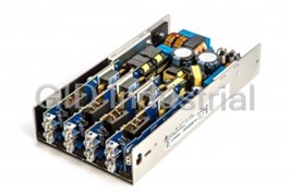
Excelsys
COOLPAC, 4 slots, Medical rated, 600W NO-FAN, 4.5"Wx8.5"Dx1.54"H, this case requires using all COOLM...
COOLPAC, 4 slots, Medical rated, 600W NO-FAN, 4.5"Wx8.5"Dx1.54"H, this case requires using all COOLM...
CX06S-0000-C-B
600W Fanless Standard w/ IEC Plug,Normal leakage
COOLPAC, 4 slots, standard, 600W NO-FAN, 4.5"Wx8.5"Dx1.54"H, this case requires using all COOLMOD mo...
Request a Quote

The quote request has been received
Close

Facing challenges or have inquiries? Feel free to contact us!
Call Us +1-469-283-2440
What they say about us
FANTASTIC RESOURCE
One of our top priorities is maintaining our business with precision, and we are constantly looking for affiliates that can help us achieve our goal. With the aid of GID Industrial, our obsolete product management has never been more efficient. They have been a great resource to our company, and have quickly become a go-to supplier on our list!
Bucher Emhart Glass
EXCELLENT SERVICE
With our strict fundamentals and high expectations, we were surprised when we came across GID Industrial and their competitive pricing. When we approached them with our issue, they were incredibly confident in being able to provide us with a seamless solution at the best price for us. GID Industrial quickly understood our needs and provided us with excellent service, as well as fully tested product to ensure what we received would be the right fit for our company.
Fuji
HARD TO FIND A BETTER PROVIDER
Our company provides services to aid in the manufacture of technological products, such as semiconductors and flat panel displays, and often searching for distributors of obsolete product we require can waste time and money. Finding GID Industrial proved to be a great asset to our company, with cost effective solutions and superior knowledge on all of their materials, it’d be hard to find a better provider of obsolete or hard to find products.
Applied Materials
CONSISTENTLY DELIVERS QUALITY SOLUTIONS
Over the years, the equipment used in our company becomes discontinued, but they’re still of great use to us and our customers. Once these products are no longer available through the manufacturer, finding a reliable, quick supplier is a necessity, and luckily for us, GID Industrial has provided the most trustworthy, quality solutions to our obsolete component needs.
Nidec Vamco
TERRIFIC RESOURCE
This company has been a terrific help to us (I work for Trican Well Service) in sourcing the Micron Ram Memory we needed for our Siemens computers. Great service! And great pricing! I know when the product is shipping and when it will arrive, all the way through the ordering process.
Trican Well Service
GO TO SOURCE
When I can't find an obsolete part, I first call GID and they'll come up with my parts every time. Great customer service and follow up as well. Scott emails me from time to time to touch base and see if we're having trouble finding something.....which is often with our 25 yr old equipment.
ConAgra Foods