

 Manufacturers
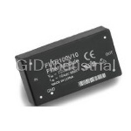
GE CRITICAL POWER FLTR100V10-62Z
Description
Electromechanical Filter 10A
Part Number
FLTR100V10-62Z
Price
Request Quote
Manufacturer
GE CRITICAL POWER
Lead Time
Request Quote
Category
Power » Power Accessories
Specifications
Manufacturer
GE Critical Power
Manufacturers Part #
FLTR100V10-62Z
Industry Aliases
CC109103801, FLTR100V10-62Z
Brand
GE Critical Power
Factory Pack Quantity
128
Datasheet

Extracted Text
GE Critical Power FLTR100V10 Filter Module 75 Vdc Input Maximum, 10 A Maximum RoHS Compliant The FLTR100V10 Filter Module in low- profile packages, have high and layout, the Lineage Power filter is designed to reduce the interwinding capacitance that can module will significantly reduce the conducted common-mode and increase common-mode current levels. conducted differential and differential-mode noise on input or Also, metal substrates used to facilitate common-mode noise returned to output lines of high-frequency switching heat transfer from the power train the power source. CISPR and FCC power supplies. The module has a components to an external heat sink add class B requirements can be met maximum current rating of 10 A. It to common-mode noise because of the by using the filter as described provides high insertion loss throughout large capacitance between switching in the following sections. the frequency range regulated by the U.S. components and the metal substrate. Federal Communications Commission • Common-mode and differential-mode (FCC) and the International Special filtering of power supply dc input and Many international agencies specify Committee on Radio Interference output lines conducted and radiated emissions (CISPR) for conducted emissions. limits for electronic products. Included The module is 51 mm long, 28 mm wide, • Computer applications among these are CISPR, FCC, VCCI, and 12 mm high (2.0 in. x 1.1 in. x 0.46 in.) • Communications equipment and the new CE specifications. Most and mounts on a PC board in a natural agency-conducted noise limits apply • Compliant to RoHS EU Directive convection or forced-air environment. only to noise currents induced onto 2011/65/EU the ac power lines in finished products. • Compatible in Pb- free or SnPb European Telecommunication Standard Introduction reflow environment Instructions (ETSI) are an exception, High-density power modules are usually • Small size: 51 mm x 28 mm x 12 mm applying CE requirements to dc supplies designed to operate at a high switching (2.0 in. x 1.1 in. x 0.46 in.) with cables over three meters long. frequency to reduce the size of the Although not required to do so by agency • Optimized for use with high-frequency internal filter components. The small standards, some system designers apply dc-to-dc power modules EMI filters internal to the modules are the conducted emissions requirements often inadequate to meet stringent • Printed-circuit board mountable to subassemblies within the product to international EMI requirements. Many • Operating case temperature range: reduce internal interference between high-density electronic packaging –40 °C to +100 °C subsystems and to reduce the difficulty techniques can increase the noise of meeting overall system requirements. • CAN/CSA C22.2 No. 60950-1-07 conducted onto the modules’ input and / UL* 60950-1, Second Edition, output lines. For example, the close dated March 27, 2007 proximity of switching components to To meet these requirements, external the input pins increases internal noise • CE mark meets 73/23/EEC and 93/68/ filtering of the power module is often coupling; and planar transformers, EEC directives‡ required. When used in conjunction with designed to handle high-power levels the recommended external components Absolute Maximum Ratings Stresses in excess of the absolute maximum ratings can cause permanent damage to the device. These are absolute stress ratings only. Functional operation of the device is not implied at these or any other conditions in excess of those given in the operations sections of the data sheet. Exposure to absolute maximum ratings for extended periods can adversely affect device reliability. PARAMETER SYMBOL MIN MAX UNIT Input Voltage: VI — 75 Vdc Continuous VI, trans — 100 V Transient (100 ms) Voltage from GND to Either Input Lead (1 minute) — — 1500 Vdc Operating Case Temperature Tc -40 100 °C Storage Temperature* Tstg –55 125 °C * For the processing, handling and storage (module not powered), the filter module can handle -55°C to 125°C exposure. Electrical Specifications Unless otherwise indicated, specifications apply over all operating input voltage and temperature conditions. PARAMETER SYMBOL MIN TYP MAX UNIT Resistance per Leg R — — 14 mΩ Maximum Average Current I max — — 10 A (TA = 60 °C, 2.0 m/s (400 lfm) air) Maximum Average Current I max — — 6.5 A (TA = 74 °C, natural convection) Common-mode Insertion Loss — — 36 — dB (50 Ω circuit, 500 kHz) Differential-mode Insertion Loss — — 44 — dB (50 Ω circuit, 500 kHz) 2 Filter Modules Datasheet | www.gecriticalpower.com Characteristics Figure 1. Derating output current vs. Local ambient temperature and Airflow (Vin =48Vdc) Figure 3. Typical Differential-Mode Insertion Loss in a 50 Ω Circuit Figure 2. Typical Common-Mode Insertion Figure 4. MTBF vs Ambient temperature for Loss in a 50 Ω Circuit 6A, 8A, and 10A Input Current Filter Modules Datasheet | www.gecriticalpower.com 3 Characteristics (continued) Table 1: MTBF in Hours: AMP TEMP 10A 8A 6A 7 7 8 20 4.124•10 8.563•10 1.451•10 7 7 7 30 2.615•10 5.284•10 8.781•10 7 7 7 40 1.707•10 3.363•10 5.486•10 7 7 7 50 1.144•10 2.201•10 3.529•10 6 7 7 60 7.854•10 1.478•10 2.331•10 6 7 7 70 5.511•10 1.015•10 1.577•10 6 6 7 80 3.946•10 7.127•10 1.091•10 Table 2: Failure Rate in FITs: AMP TEMP 10A 8A 6A 20 24.248 11.679 6.89 30 38.244 18.925 11.388 40 58.588 29.736 18.227 50 87.415 45.433 28.336 60 127.327 67.671 42.899 70 181.441 98.481 63.394 80 253.416 140.302 91.632 Internal Schematics Figure 5. Internal Schematic 4 Filter Modules Datasheet | www.gecriticalpower.com Application Conducted noise on the input power Common-mode noise is best attenuated exceed 10 A. Figure 8 shows the lines can occur as either by capacitors from power module input recommended schematic for two power differential-mode or common-mode to power module output, capacitors from modules attached to a single filter. noise currents. Differential-mode noise is each input line to a shield plane (Y caps), measured between the two input lines, and common-mode chokes. It is In applications where the addition of and is found mostly at the low- frequency recommended that ceramic input to output capacitors is undesirable, end of the spectrum. This noise capacitors be added around each do not use C3 and C4 shown in shows up as noise at the fundamental power module from each input and Figures 6 and 7, and do not use C3, switching frequency and its harmonics. output pin to a shield plane under C4, C8, and C9 shown in Figure 8. Common-mode noise is measured the module. The shield plane should between the input lines and ground be connected to the CASE pin. and is mostly broadband noise above In –48 V applications where the shield 10 MHz. The high-frequency nature of plane and the power module case The GND pin of the filter module is common-mode noise is mostly due to must be tied to a signal, remove C1 in attached to Y caps within the module. the high-speed switching transitions Figures 6 and 7, remove C1 and C6 in This pin should be tied to a quiet chassis of power train components. Either or Figure 8, and connect the shield plane ground point away from the power both types of noise may be covered in a and CASE pin to the VI(+) plane. modules. GND of the filter module should specification, as well as a combination not be tied to the CASE pin of the power of the two. An approved measurement module since this is a noisy node and technique is often described, as well. In +48 V applications where the shield will inject noise into the filter, increasing plane and the power module case the input common-mode noise. must be tied to a signal, remove C2 in Differential-mode noise is best Figures 6 and 7, remove C2 and C7 in attenuated using a filter composed of Figure 8, and connect the shield plane If no quiet grounding point is available, line-to-line capacitors (X caps) and and CASE pin to the VI(–) plane. it is best to leave the filter module GND series inductance, provided by either pin unattached. Each power system a discrete inductor or the leakage design will be different, and some inductance of a common-mode experimentation may be necessary choke. In addition to the differential to arrive at the best configuration. filtering provided by the filter module, it is recommended that an electrolytic capacitor be located at the converter Figure 6 shows a typical schematic of side of the filter to provide additional a power module with filter module and attenuation of low-frequency recommended external components. differential noise and to provide a low Figure 7 is a proposed layout. More source impedance for the converter, than one power module may be preventing input filter oscillations attached to a single filter module and load- transient induced as long as input current does not input voltage dips. Filter Modules Datasheet | www.gecriticalpower.com 5 Application (continued) Figure 6. Recommended Schematic When Used as the Input Filter to a High-Frequency dc-to-dc Converter Figure 7. Recommended Layout When Used as the Input Filter to a High-Frequency dc-to-dc Converter Filter Modules Datasheet | www.gecriticalpower.com 6 Application (continued) Figure 8. Recommended Schematic of Filter Module with Two Power Modules 7 Filter Modules Datasheet | www.gecriticalpower.com Application (continued) Thermal Considerations Figures 9 and 10 show some experimental results obtained Filter modules operate in a variety of thermal by using the filter module, together with the recommended environments; however, sufficient cooling should external components shown in Figures 6 and 7. be provided to help ensure reliable operation. The JW075A5 module is a lower-noise version of the standard Considerations include ambient temperature, airflow, JW series with internal modifications to the power module. module power dissipation, and the need for increased The lower noise of the JW075A5 module is achieved at the reliability. A reduction in the operating temperature of cost of lower efficiency, and a reduced maximum power the module will result in an increase in reliability. rating. Measured noise is highly dependent on layout, grounding, cable orientation, and load characteristics and The thermal data presented in the data sheet is based will, therefore, vary from application to application. on physical measurements taken in a wind tunnel. The thermal reference point used for thermal derating curves presented in Figure 1 is the case of the module. For reliable operation this temperature should not exceed 100°C. Other Considerations It is essential for good EMI performance and may actually increase the noise remote-sense leads sense the output that the input lines not be contaminated conducted onto the input lines. voltage before the common-mode filter. with noise after passing through the filter. Adding Y caps to the input side of the Do not use remote-sense on the load Filtered input traces should therefore filter module couples any noise in the side of an output common-mode filter. be kept away from noise sources such ground plane directly into the input as power modules and switching logic lines, usually degrading performance. If input noise performance is lines. If input voltage sense traces must Adding additional X and Y caps to unsatisfactory after applying the filter be routed past the power modules from the power module side of the filter module as described previously, the the quiet side of the filter module, they module produces low- impedance best remedy is to modify the layout and should be filtered at the point where loops for high-frequency currents to grounding scheme. It is often useful they leave the quiet input lines. Input flow, possibly degrading performance. to make a model of the power card, traces should be kept as far away from using copper tape and a vector card, output power traces as possible. Adding additional common-mode or to experiment with various layout differential-mode filtering to the power and grounding approaches prior to The fundamental switching frequency module output leads decreases the committing to a printed-wiring board. noise spike can be somewhat reduced power module output noise, and also by adding a high-frequency capacitor frequently reduces the input noise by of a few microfarads across the decreasing the noise coupled from input lines of the filter module. output leads to input leads. Common-mode output filtering is particularly important if the load is Adding additional components to the tied to chassis ground. input filter to improve performance If common-mode filtering is added to usually has very limited payback, the power module output, ensure that Filter Modules Datasheet | www.gecriticalpower.com 8 Other Considerations (continued) Figure 9. JW075A1 Conducted Noise with Filter Figure 10. JW075A5 Conducted Noise with Filter Filter Modules Datasheet | www.gecriticalpower.com 9 Outline Diagram Dimensions are in millimeters and (inches). Tolerances: x.x ± 0.5 mm (0.02 in.), x.xx ± 0.25 mm (0.010 in.). Top View Side View Bottom View Filter Modules Datasheet | www.gecriticalpower.com 10 Recommended Hole Pattern Component-side footprint. Dimensions are in millimeters and (inches). Tolerances: x.x ± 0.5 mm (0.02 in.), x.xx ± 0.25 mm (0.010 in.).. Note: Do not route copper paths beneath power module standoffs. Post Solder Cleaning and Through-Hole Lead Free Drying Considerations Soldering Information Post solder cleaning is usually the final circuit-board The RoHS-compliant through-Hole products use the assembly process prior to electrical board testing. SAC(Sn/Ag/Cu) Pb-free solder and RoHS- compliant The result of inadequate cleaning and drying can affect components. They are designed to be processed through both the reliability of a power module and the testability single or dual wave soldering machines. The pins have an of the finished circuit-board assembly. For guidance on RoHS-compliant finish that is compatible with both Pb and appropriate soldering, cleaning and drying procedures, Pb-free wave soldering processes. A Maximum preheat refer to Lineage Power Board Mounted Power rate 30C/s is suggested. The wave preheat process should Modules: Soldering and Cleaning Application Note. be such that the temperature of the power module board is kept below 2100C. For Pb solder, the recommended pot temperature is 2600C, while the Pb-free solder pot is 2700C max. Not all RoHS-compliant through-hole products can be processed with paste-through-hole Pb or Pb-free reflow process. If additional information is needed, please consult with your Lineage Power representative for more details. Filter Modules Datasheet | www.gecriticalpower.com 11 Ordering Information DEVICE CODE COMCODE DESCRIPTION FLTR100V10Z 109100154 Standard Pin Length RoHS compliant * UL is a registered trademark of Underwriters Laboratories, Inc. †CSA is a registered trademark of Canadian Standards Assn. GE ‡This product is intended for integration into end-use equipment. All the required procedures for CE marking of end-use equipment should be followed. (The CE mark is placed on selected products.) Critical Power 601 Shiloh Road *Registered trademark of the General Electric Company. The GE brand, logo, and lumination are trademarks of the General Electric Company. © 2015 General Electric Company. Plano, TX 75074 Information provided is subject to change without notice. All values are design or typical values when measured under laboratory conditions. +1 888 546 3243 www.gecriticalpower.com 04/2015
Frequently asked questions
How does Electronics Finder differ from its competitors?

Is there a warranty for the FLTR100V10-62Z?
Which carrier will Electronics Finder use to ship my parts?
Can I buy parts from Electronics Finder if I am outside the USA?
Which payment methods does Electronics Finder accept?
Why buy from GID?

Quality
We are industry veterans who take pride in our work

Protection
Avoid the dangers of risky trading in the gray market

Access
Our network of suppliers is ready and at your disposal

Savings
Maintain legacy systems to prevent costly downtime

Speed
Time is of the essence, and we are respectful of yours
Related Products

AC INPUT CABLE FOR CLP0212, 50
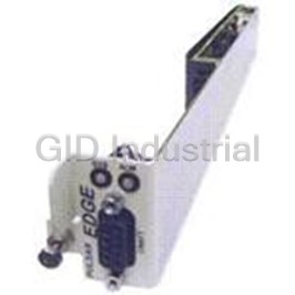
CP841A_3C3R_S CONTROLLER, EDGE CONTROLLER FOR CP2XXX AND CP3XXX SHELVES
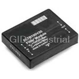
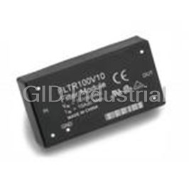
Electromechanical Filter 50Ohm 20A
Electromechanical Filter 10A
EMI Filter Module 5A 75VDC PC Pins Thru-Hole
Request a Quote

The quote request has been received
Close

Facing challenges or have inquiries? Feel free to contact us!
Call Us +1-469-283-2440
What they say about us
FANTASTIC RESOURCE
One of our top priorities is maintaining our business with precision, and we are constantly looking for affiliates that can help us achieve our goal. With the aid of GID Industrial, our obsolete product management has never been more efficient. They have been a great resource to our company, and have quickly become a go-to supplier on our list!
Bucher Emhart Glass
EXCELLENT SERVICE
With our strict fundamentals and high expectations, we were surprised when we came across GID Industrial and their competitive pricing. When we approached them with our issue, they were incredibly confident in being able to provide us with a seamless solution at the best price for us. GID Industrial quickly understood our needs and provided us with excellent service, as well as fully tested product to ensure what we received would be the right fit for our company.
Fuji
HARD TO FIND A BETTER PROVIDER
Our company provides services to aid in the manufacture of technological products, such as semiconductors and flat panel displays, and often searching for distributors of obsolete product we require can waste time and money. Finding GID Industrial proved to be a great asset to our company, with cost effective solutions and superior knowledge on all of their materials, it’d be hard to find a better provider of obsolete or hard to find products.
Applied Materials
CONSISTENTLY DELIVERS QUALITY SOLUTIONS
Over the years, the equipment used in our company becomes discontinued, but they’re still of great use to us and our customers. Once these products are no longer available through the manufacturer, finding a reliable, quick supplier is a necessity, and luckily for us, GID Industrial has provided the most trustworthy, quality solutions to our obsolete component needs.
Nidec Vamco
TERRIFIC RESOURCE
This company has been a terrific help to us (I work for Trican Well Service) in sourcing the Micron Ram Memory we needed for our Siemens computers. Great service! And great pricing! I know when the product is shipping and when it will arrive, all the way through the ordering process.
Trican Well Service
GO TO SOURCE
When I can't find an obsolete part, I first call GID and they'll come up with my parts every time. Great customer service and follow up as well. Scott emails me from time to time to touch base and see if we're having trouble finding something.....which is often with our 25 yr old equipment.
ConAgra Foods