

 Manufacturers
GRAYHILL 12C1087-1

Description
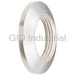
Switch Access Rotary Switch Non Turn Washer
12C1087-1
Part Number
12C1087-1
Price
Request Quote
Manufacturer
GRAYHILL
Lead Time
Request Quote
Category
Sensors and Transducers » Switch Accessories
Specifications
Manufacturer
Grayhill
Manufacturers Part #
12C1087-1
Industry Aliases
12C1087-1
Sub-Categories
Switch Accessories
Series
12
Factory Pack Quantity
1
Datasheet

Extracted Text
4 3 5 4 6 Rotary Switches 5 7 6 8 7 9 Multi-Deck Rotary Switches SERIES 42, 43, 44 and 54 1" Diameter, 1 Amp, Standard, Military SR04 FEAtuRES • Rugged Construction Ensures Switch Operation for the Life of your Equipment • Many Circuitry Options • MIL Qualified Versions MIL-S-3786/04 • Features Choice Include: Shaft/ Panel Seal, Adjustable Stops, PC Termination, UL Recognized DIMENSIONS in inches (and millimeters) Standard, uL Recognized and Rear Views Military Qualified Solder Lug Styles Series 42 1.015 ± .015 (25,78 ± 0,38) DIA. OVER TERMINALS DIM. A + .046 –.020 DIM. D .437 .437 (+ 0,05 –0,51) ± .010 (0,25) DIA. ± .020 ± .020 OF NON-TURN (11,10 C (11,10 L TAB ± 0,51) ± 0,51) DIM. B REF. .375 STUD ± .015 .250 DIM. F ± .015 (0,38) PROJECTION (9,53 36° ± .020 ± 0,38) (6,35 #1 THREAD ± 0,51) .064 (1,63) MIN. DIA. DIM. E HOLE AFTER PLATING .219 ± .010 (0,25) ± .005 (5,56 Series 44 ± 0,13) .250 + .001 –.002 (6,35 + 0,03 –0,05) 1.170 ± .015 DIA. (29,72 ± 0,38) DIA. DIM. C OVER TERMINALS ± .015 (0,38) C OF BUSHING INTEGRAL ASSEMBLy NUT, L KEyWAy DO NOT REMOVE SEE NOTE BUSHING KEyWAy NON-TURN TAB .066 ± .002 (1,68 ± 0,05) WIDE By .125 ± .003 (3,18 ± 0,08) WIDE By .036 ± .003 (0,91 ± 0,08) DEEP .031 ± .003 (0,79 ± 0,08) THICK FROM A .375 (9,53) DIA. 15° 3/8-32 UNEF-2A THREAD (MTG. HOLE = 3/8 DIA. MIN.) 30° Note: Common location for a single pole per deck switch. For common location on multi-pole switches, see circuit .064 (1,63) MIN. DIA. diagrams. HOLE AFTER PLATING For rear view of 45°, 60° and 90°, see circuit diagram. No. Dimension B Approx. Weight No. Dimension B Approx. Weight of Dimension Style Style Grams of Dimension Style Style Grams Decks A A M or H 42 44 Decks A A M or H 42 44 1 1.025 (26,04) .062 (1,57) .030 (0,76) 40.0 48 7 3.351 (85,16) .312 (7,92) .280 (7,11) 73.0 90 2 1.371 (34,82) .062 (1,57) .030 (0,76) 45.5 55 8 3.697 (93,90) .312 (7,92) .280 (7,11) 78.5 97 3 1.717 (43,61) .062 (1,57) .030 (0,76) 51.0 62 9 4.043 (102,69) .312 (7,92) .280 (7,11) 84.0 104 4 2.063 (52,40) .062 (1,57) .030 (0,76) 56.5 69 10 4.389 (111,48) .312 (7,92) .280 (7,11) 89.5 111 5 2.409 (61,19) .062 (1,57) .030 (0,76) 62.0 76 11 4.735 (120,27) .312 (7,92) .280 (7,11) 95.0 118 6 3.005 (76,33) .312 (7,92) .280 (7,11) 67.5 83 12 5.081 (129,06) .312 (7,92) .280 (7,11) 100.5 125 Grayhill part number and date code marked on detent cover label. Dimension C D E F Customer part number marked on request. Military part number marked when required. UL recognized markings as required. Series 42 .562 (14,27) 1.000 (25,4) .830 (21,08) .093 (2,36) Series 44 .642 (16,31) 1.162 (29,51) 1.000 (25,4) .121 (3,07) Grayhill, Inc. • 561 Hillgrove Avenue • LaGrange, Illinois 60525-5997 • USA • Phone: 708-354-1040 • Fax: 708-354-2820 • www.grayhill.com 8 10 9 11 12 10 GRAyHILL GRAyHILL 1 1 2 3 2 3 2 3 4 Rotary Switches 3 4 5 6 5 Multi-Deck Rotary Switches CIRCuIt DIAGRAMS: Solder Lug terminals Switch is Viewed From Shaft End and Shown in Position No. 1 Note: All common terminals are located above base terminals as shown. C OF L C3 C3 BUSHING 9 10 9 9 9 10 10 10 8 11 KEyWAy 8 11 8 8 11 11 Series 44 & 54 12 7 7 C2 12 12 7 12 7 C C 30° Angle C1 C C2 L L L 6 6 1 6 6 1 of throw C1 1 C1 1 5 5 5 5 2 2 2 2 C2 4 3 3 3 4 3 4 4 C1 ONE POLE TWO POLE THREE POLE THREE POLE Styles A, D and S Styles M, MS, H and HS C5 C4 9 9 10 C6 10 11 8 8 11 C3 7 7 C4 12 12 C C L L 6 6 1 C1 1 C1 5 5 2 2 C3 4 3 3 4 C2 C2 FOUR POLE FIVE OR SIX POLE C OF L BUSHING 8 7 7 8 C2 KEyWAy 6 9 9 6 Series 42 & 43 10 C 5 C1 5 L 36° Angle 10 of throw 1 4 4 1 C1 3 32 2 ONE POLE TWO POLE Rear Views C OF L C4 BUSHING 7 6 7 6 7 KEyWAy 6 8 8 8 5 C3 Series 44 5 C2 5 C C1 C 45° Angle L L 1 1 15° 1 4 C1 4 4 of throw C1 2 2 3 3 2 3 C2 45° ONE POLE TWO POLE THREE OR FOUR POLE C OF L C3 BUSHING 5 5 5 6 KEyWAy 6 6 Series 44 4 C2 4 4 C1 C C 60° Angle L L 15° 1 1 C1 1 C1 of throw 3 3 3 C2 2 2 2 60° ONE POLE TWO POLE THREE POLE C OF L BUSHING 4 4 KEyWAy 3 C2 Series 44 3 C C1 L 90° Angle 1 C1 15° 1 of throw 2 2 90° ONE POLE TWO POLE Grayhill, Inc. • 561 Hillgrove Avenue • LaGrange, Illinois 60525-5997 • USA • Phone: 708-354-1040 • Fax: 708-354-2820 • www.grayhill.com 4 7 8 6 GRAyHILL GRAyHILL GRAyHILL 1 1 1 2 2 6 2 FIRST STOP FIRST STOP 7 GRAYHILL Rotary Switches 8 9 11 9 8 10 10 Multi-Deck Rotary Switches SERIES 42 1" Diameter, 1 Amp, PC Mount FEAtuRES • Satisfies High Current Board Level Applications • 36° Angle of Throw Permits up to Ten Positions • UL Recognized Versions DIMENSIONS in inches (and millimeters) DIM. A + .046 – .020 Standard Style .437 ± .020 (+1,17 –0,00) 1.000 ± .010 DIM. B REF. (11,10 ± 0,51) C C C (25,4 ± 0,25) .786 ± .010 L STUD L L .600 ± .031 DIA. PROJECTION (19,96 ± 0,25) (15,24 ± 0,79) .174 DIA. .174 ± .010 ± .010 (4,42 ± 0,25) (4,42 #1 THREAD .250 ± .020 ± 0,25) (6,35 ± 0,51) .500 ± .015 .219 (12,7 ± 0,38) ± .005 .830 TYP. (5,56 .750 ± .010 ± .010 ± 0,13) (19,05 ± 0,25) (21,08 TYP. ± 0,25) .250 + .001 –.002 (6,35 + 0,03 –0,05) .375 ± .015 DIA. COMMON LUG (9,53 ± 0,38) TYP. .250 ± .015 INTEGRAL ASSEMBLY NUT, (6,35 ± 0,38) TYP. DO NOT REMOVE TERMINAL DIMENSIONS AT THIS .187 ± .015 POINT ARE .050 ± .005 (1,27 ± 0,13) BUSHING KEYWAY (4,75 ± 0,38) TYP. WIDE BY .020 ± .003 (0,51 ± 0,08) THICK .066 ± .002 (1,68 ± 0,05) WIDE BY .735 ± .010 .036 ± .003 (0,91 ± 0,08) DEEP C OF BUSHING L (18,67 ± 0,25) TYP. FROM A .375 (9,53) DIA. KEYWAY 1.470 ± .020 Grayhill part number and date code marked on detent cover label. Customer part num- 3/8-32 UNEF-2A THREAD (37,34 ± 0,51) ber marked on request. UL recognized marking as required. TYP. (MTG. HOLE=3/8 DIA. MIN.) CIRCuIt DIAGRAM: PC Mount PC BOARD MOuNtING PAttERN SHAFt AND PANEL SEAL: Srs. 42 & 44 Shown for a two deck switch Switch is Viewed From Shaft End Standard Style and Shown in Position No. 1 The Series 42/44 Styles, which include the letter "S" with Note: All common terminals are located above C OF FRONT SUPPORT the exception of style "HS", are watertight sealed to the L C OF BASE base terminals as shown. PLATE MOUNTING L mounting panel by utilizing the panel seal kit. These switches TERMINAL HOLES are built with a front plate that does not have a non-turn tab. .375 MOUNTING termination The panel seal kit consists of a grooved hex nut, a keyed (9,53) HOLES One-sided termination is standard for switches with 2 to 5 washer and a keyed panel seal. The grooved hex nut is TyP. positions per pole. Two-sided termination is standard for C OF REAR assembled to the switch bushing. The keyed washer is slid L .500 switches with 6 thru 10 positions per pole. SUPPORT down the bushing slot and seated into the hex nut groove. (12,7) PLATE The seal is likewise assembled to the bushing and hex nut. C OF TyP. L MOUNTING The keyed washer is required to provide seal integrity in the BUSHING 10 .750 6 thru 10 positions 1 HOLES bushing slot. When assembled to the panel, the grooved KEyWAy (19,05) per pole and ter- .250 2 9 nut, backing washer and seal require the same space as a C COMMON TyP. minals from one (6,35) L normal mounting nut. Hence, the seal kit does not alter the TERMINAL TyP. side of switch are 8 C1 dimensions. Panel seal kit includes a non-turn washer to MOUNTING 3 available on special .174 (4,42) be used into a blind hole in the back panel. For panel seal HOLES order. See Special 4 TyP. kit part dimensions, see Accessories. Style "HS" switches 7 Options, page F-10 .492 use a similar sealing method, except the integral assembly 65 .110 (2,79) or contact Grayhill. (12,50) nut retains the panel seal. All sealed style switches are provided with a shaft to bushing internal seal. .174 (4,42) TyP. ONE POLE ADJuStABLE StOP SWItCHES: Series 42 and 44 The standard and UL recognized switches are also Equivalent Styles For style 44M30, use 44D30 initially available with adjustable stops. Two removable For style 42A36, use 42D36, For style 42u36, use 42uD36 For style 44A30, use 44D30 stop washers allow you to limit the number of For style 42M36, use 42D36 initially For style 44u30, use 44uD30 switch positions as needed. A knurled nut is supplied to secure the washers if desired. These switches have no bushing keyway. All other Front Views dimensions, ratings and characteristics are the same as the standard fixed stop styles. Although not military qualified, the adjustable styles are useful in military equipment prototypes. However, USE OF KNURLED when submitting the equipment for government NUT IS OPTIONAL approval, the fixed stop qualified style should ADJUSTABLE STOP Series 42 Series 44 be substituted. WASHERS Grayhill, Inc. • 561 Hillgrove Avenue • LaGrange, Illinois 60525-5997 • USA • Phone: 708-354-1040 • Fax: 708-354-2820 • www.grayhill.com 9 1 8 6 2 7 5 6 3 SHAFT END 4 5 4 3 4 5 3 4 3 5 4 6 Rotary Switches 5 7 6 8 7 9 Multi-Deck Rotary Switches SERIES 43 SERIES 54 1" Diameter, 1 Amp, Concentric Shafts FEAtuRES • Two Switches in the Panel Space of a Single Shaft Rotary • Military Qualified Versions MIL-3786/04 • Choice of 10 Positions (Series 43) or 12 Positions (Series 54) DIMENSIONS in inches (and millimeters) Standard Style and Military Qualified Rear Views 1.162 (29,51) DIA. DIM. A + .046 –.020 .375 .375 Series 43 SER. 54 (+0,05 –0,51) ± .020 ± .020 1.000 (25,4) DIA. (9,53 (9,53 SER. 43 ± 0,51) ± 0,51) 1.015 ± .015 .250 ± .020 (6,35 ± 0,51) OF NON-TURN C (25,78 ± 0,38) DIM. B REF. L .375 TAB .093 ± .015 (2,36 ± 0,38) OVER TERMINALS STUD ± .015 .250 ± .020 SER. 43 PROJECTION (9,53 (6,35 ± 0,51) .121 ± .015 (3,07 ± 0,38) SER. 54 #1 THREAD ± 0,25) .250 ± .020 (6,35 ± 0,51) .830 (21,08) SER. 43 1.000 (25,4) SER. 54 .125 + .001 –.002 ± .010 (0,25) .094 ± .004 36° (3,18 + 0,03 –0,05) DIA. (2,39 ± 0,10) .250 + .001 –.002 .642 (16,31) .219 ± .005 (6,35 + 0,03 –0,05) DIA. SECTION SER. 54 SECTION (5,56 ± 0,13) A .562 (14,27) B .064 (1,63) MIN. DIA. CONTROLLED By SER. 43 C OF BUSHING L HOLE AFTER PLATING .250 (6,35) .125 (3,18) ±.015(0,38) KEyWAy DIA. SHAFT SEE NOTE MILITARy NUMBER MARKED ON ALL NON-TURN TAB QUALIFIED SWITCHES .125 ± .003 (3,18 ± 0,08) WIDE By INTEGRAL ASSEMBLy NUT, DO NOT REMOVE .031 ± .003 (0,79 ± 0,08) THICK BUSHING KEyWAy .066 ± .002 (1,68 ± 0,05) WIDE By .036 ± .003 (0,91 ± 0,08) DEEP FROM Series 54 A .375 (9,53) DIA. Note: Common location for a single pole per 3/8-32 UNEF-2A THREAD deck switch. For common location on 1.170 ± .015 multi-pole switches, see circuit (29,72 ± 0,38) DIA. diagrams. OVER TERMINALS Number of Approx. Weight Decks Dimension A Dimension B Grams Section Section Style Style Style Series Series “A” “B” A, M or H A M or H 43 54 1 1 1.818 (46,18) .062 (1,57) .030 (0,76) 48 60 15° 2 1 2.164 (54,97) .062 (1,57) .030 (0,76) 54 67 3 1 2.510 (63,75) .062 (1,57) .280 (7,11) 60 74 30° 1 2 2.164 (54,97) .062 (1,57) .030 (0,76) 54 67 2 2 2.510 (63,75) .062 (1,57) .280 (7,11) 60 74 3 2 3.105 (78,87) .312 (7,92) .280 (7,11) 66 81 .064 (1,63) MIN. DIA. 1 3 2.510 (63,75) .062 (1,57) .280 (7,11) 60 74 HOLE AFTER PLATING 2 3 3.105 (78,87) .312 (7,92) .280 (7,11) 66 81 3 3 3.451 (87,66) .312 (7,92) .280 (7,11) 72 88 Grayhill part number and date code marked on detent cover label. Customer part number marked on request. Military part number marked when required. Grayhill, Inc. • 561 Hillgrove Avenue • LaGrange, Illinois 60525-5997 • USA • Phone: 708-354-1040 • Fax: 708-354-2820 • www.grayhill.com 8 10 9 11 12 10 GRAyHILL GRAyHILL 1 1 2 3 2 4 3 2 FIRST STOP 5 4 FIRST STOP 6 Rotary Switches 5 7 9 11 6 8 8 10 7 9 7 Multi-Deck Rotary Switches SERIES 43 and 54 1" Diameter, 1 Amp, Add-A-Pot FEAtuRES • Central Shaft Designed to Operate an Add-On Potentiometer • Potentiometer Mounting Plates Provided • Adjustable Stop Standard, Fixed Stop by Order • Choice of 10 Positions (Series 43) or 12 Positions (Series 54) DIMENSIONS In inches (and millimeters) Standard Style Rear Views Series 43 1.000 ± .010 DIM. A + .046 –.020 .625 ± .046 .375 .375 (25,4 ± 0,25) (+0,05 –0,51) (15,88 ± 1,17) Series 43 ± .020 ± .020 DIA. (9,53 (9,53 .093 ± .015 (2,36 ± 0,38) ± 0,51) ± 0,51) SER. 43 1.015 ± .015 C OF NON-TURN .121 ± .015 (3,07 ± 0,38) L (25,78 ± 0,38) .375 TAB SER. 54 OVER TERMINALS ± .015 .250 ± .020 (6,35 ± 0,51) (9,53 .250 ± .020 ± 0,38) .140 ± .062 (6,35 ± 0,51) (3,56 ± 1,57) #1 THREAD .250 ± .020 (6,35 ± 0,51) .830 (21,08) SER. 43 1.000 (25,4) SER. 54 ± .010 (0,25) .125 + .001 –.002 36° .094 ± .004 (3,18 + 0,03 –0,05) DIA. (2,39 ± 0,10) .250 + .001 –.002 .562 .219 ± .005 (6,35 + 0,03 –0,05) DIA. ± .015 (5,56 ± 0,13) (14,27 .064 (1,63) MIN. DIA. STOP WASHERS ± 0,38) HOLE AFTER PLATING SEE NOTE USE OF KNURLED NUT NON-TURN TAB OPTIONAL .125 ± .003 (3,18 ± 0,08) WIDE By 3/8-32 UNEF-2A THREAD .031 ± .003 (0,79 ± 0,08) THICK Series 54 Note: Common location for a single pole per Series 54 deck switch. For common location on multi-pole switches, see circuit diagrams. 1.162 ± .010 1.170 ± .015 (29,51 ± 0,25) (29,72 ± 0,38) DIA. OVER TERMINALS Approx. Weight Number Grams 9 of Dimension Decks A Series 43 Series 54 1 .974 (24,74) 48 60 2 1.320 (33,53) 54 67 15° 3 1.666 (42,32) 60 74 30° .642 ± .015 (16,31 ± 0,38) Two potentiometer mounting plates are Plated brass spacers for ease of positioning Standard style, concentric shaft, add-a-pot supplied. Mounting plates have .261 (6,63) mounting plate driving assembly are available switches have adjustable stops. See Adjustable and .380 (9,65) diameter holes respectively on special request (sold only with switches). The Stop description. 1 3 use of spacers is recommended for other than for mounting potentiometers with /4" and /8" bushings. Additional nuts for the through bolts prototype requirements. When ordering switches of the switch are provided for adjustment of with spacers, give full details regarding special Grayhill part number and date code marked on detent cover label. Customer part number marked on request. Military mounting plate location. Tapered tongue on length, potentiometer being used, etc. part number marked when required. 1 /8" shaft provides coupling to screwdriver slots in potentiometer shafts. Grayhill, Inc. • 561 Hillgrove Avenue • LaGrange, Illinois 60525-5997 • USA • Phone: 708-354-1040 • Fax: 708-354-2820 • www.grayhill.com 8 10 8 6 11 9 7 5 12 10 6 4 1 5 1 2 3 4 3 2 3 2 4 5 6 Rotary Switches 7 8 9 Multi-Deck Rotary Switches SERIES 54 1" Diameter, 1 Amp, Add-A-Pot FEAtuRES • Military Qualified MIL-3786/04 • Central Shaft Designed to Operate MIL Potentiometer • Mounting Plate Options Provide Choice of Potentiometer • Fixed Distance from Switch to Mounting Plate DIMENSIONS In inches (and millimeters) Military Qualified Style 1.162 ± .010 DIM. A + .046 –.020 .575 .375 .375 (29,51 ± 0,25) (+ 0,05 –0,51) (14,61) ± .020 ± .020 DIA. REF. (9,53 (9,53 1.170 ± .015 C OF NON-TURN L ± 0,51) ± 0,51) .140 ± .062 (29,72 ± 0,38) TAB (3,56 ± 1,57) .250 ± .020 OVER TERMINALS .375 (6,35 ± 0,51) ± .015 (9,53 .121 ± .015 #1 ± 0,38) (3,07 ± 0,38) .250 ± .020 THREAD (6,35 ± 0,51) 1.000 ± .010 (25,4 15° ± 0,25) .125 + .001 –.002 (3,18 + 0,03 –0,05) DIA. 30° .250 + .001 –.002 .219 ± .005 .642 SEE (6,35 + 0,03 –0,05) DIA. (5,56 ± 0,13) .018 ± .005 (0,46 ± 0,13) ± .015 POTENTIOMETER .052 ± .005 (1,32 ± 0,13) (16,31 MOUNTING ± 0,38) GRAyHILL OR CUSTOMER PART NUMBER MARKED ON SWITCH COVER UPON REQUEST. MILITARy NUMBER MARKED ON ALL QUALIFIED SWITCHES NON-TURN TAB INTEGRAL ASSEMBLy NUT, .125 ± .003 (3,18 ± 0,08) WIDE By DO NOT REMOVE .031 ± .003 (0,79 ± 0,08) THICK 3/8-32 NEF-2A THREAD BUSHING KEyWAy .066 ± .002 (1,68 ± 0,05) WIDE By .036 ± .003 (0,91 ± 0,08) DEEP FROM Note: Common locations for a single pole per A .375 (9,53) DIA. deck switch. For common location on multiple switches, see circuit diagram. Number Approximate Potentiometer Mounting of Dimension Weight The two mounting plates shown below are supplied with Decks A Grams each switch. .130 ± .003 1 1.024 (26,01) 60 (3,30 ± 0,08) 2 1.370 (34,80) 67 27.5 DIA. (2) 3 1.716 (43,59) 74 ± 2 15 ± 2 .245 ± .003 .437 ± .003 .098 ± .003 .380 ± .003 (6,22 ± 0,08) R. (11,10 ± 0,08) R. Series 54M Add-A-Pot Switch is a concentric (2,49 ± 0,08) DIA. (3) (9,65 ± 0,08) shaft unit with provision for potentiometer THROUGH BOLT DIA. (1) HOLE (2 EA.) mounting. Outer shaft operates switch decks. Inner shaft terminates in tapered tongue, .261 ± .003 (6,63 ± 0,08) DIA. (1) which allows any desired potentiometer to be 15 9 .375 ± .003 .531 ± .003 mounted. The Series 54M Add-A-Pot is qualified ± 2 ± 2 (9,53 ± 0,08) R. (13,49 ± 0,08) R. to MIL-DTL-3786/4-3. Patent No. 3,297,830. 1.265 1.265 (32,13) (32,13) DIA. DIA. Grayhill part number and date code marked on detent Mounting Plate A Mounting Plate B cover label. Customer part number marked on request. Military part number marked when required. Grayhill, Inc. • 561 Hillgrove Avenue • LaGrange, Illinois 60525-5997 • USA • Phone: 708-354-1040 • Fax: 708-354-2820 • www.grayhill.com 10 11 12 1 2 3 Rotary Switches Multi-Deck Rotary Switches MILItARy QuALIFIED specifically SR04-2. Unsealed switches are the following pages. Standard variations such Single Shaft Switches as terminals, shaft and/or bushing length etc., qualified for -65°C to 85°C in 30°, 36°, 45°, The military styles of the single shaft Series 60° and 90° throws. The standard and military which do not affect performance, can be marked 42 and 44 rotary switches are qualified to MIL- as qualified product. Adjustable stops cannot styles of the concentric switches have the same DTL-3786/4, specifically SR04-1. Qualification be qualified. Contact Grayhill for details about dimensions with the exception of the location of includes two temperature ranges. Unsealed the 3 pole common (see circuit diagrams). The variations. styles M, MB, MG and MBG are qualified for -65 30° and 36° throws are described in the ordering to 85°C. Unsealed styles H, HB, HG and HBG, information. If the 45°, 60° and 90° throws are Military qualified switches may be ordered by the plus sealed styles HS, HBS, HGS and HBGS military M number listed in MIL-DTL-3786/4 or required, they can be provided in Section A of are qualified for -65°C to 125°C. Qualification by the Grayhill part number. They will be marked the Series 54 Rotary Switches; see Standard includes low level switching and shaft grounding Options, page J-9. to specifications. as specified in MIL-DTL-3786. Qualification includes 30°, 36°, 45°, 60° and 90° angles of throw Add-A-Pot Switches MILItARy QuALIFIED SHAFt AND with solder lug terminals. The military styles are The military style of the add-a-pot Series 54 dimensionally the same as the standard styles PANEL SEAL: switch is qualified to MIL-DTL-3786/4, specifically with two exceptions. The location of the common SR04-3. These unsealed switches are qualified Styles HS, HBS, HGS and HBGS for the 3-pole switch differs (see circuit diagrams) for -65°C to 85°C in 30°, 45°, 60° and 90° throws. The shaft is sealed to the bushing by an internal and the non-turn tab for styles HS, HBS, HGS The dimensions of the military style add-a-pot O-ring per MIL-P-5516B. The bushing is sealed and HBGS differs per the Shaft and Panel Seal switches are not the same as the standard add- to the panel with a silicone rubber washer and description following. a-pot switches; see drawings. a stainless steel backing washer. The combined uncompressed thickness is 0.055" (1,40). Since two Switches, Concentric Shafts All Qualified Switches this switch has a flat cover, a non-turn washer is The M style of the concentric shaft Series 43 supplied (see Panel Seal Kit). If using it, mount Complete electrical ratings and characteristics and 54 switches is qualified to MIL-DTL-3786/4, for all of these qualified switches are listed on it in front of the panel. SPECIFICAtIONS: Electrical Ratings Standard Style Overload: 50 operations at 150% rated AC Voltage and Load: As listed in the chart load One cycle is 360° rotation and a return through Rated: To make and break the following loads: Endurance: 6000 operations at the rated load all switch positions to the starting position. The with 1000 Vac dielectric strength before and data for the curves was measured at sea level, Angle of throw after test 25°C and 68% relative humidity. 30° or 36° 45° or 60° 90° 115 Vac resistive 1 amp 5 amps 5 amps temperature Rise: Not to exceed 30°C when 6-28 Vdc resistive 1 amp 1 amp 2 amps carrying rated AC load after test. The Series 42, 43, 44 and 54, style M, H and 115 Vac inductive 0.25 amp 2 amps 2 amps Note: all dimensional drawings for the standard HS switches are made to meet requirements 115 Vdc inductive 0.02 amp — — 6-28 Vdc inductive 0.10 amp — — style Series 42, 43, 44 and 54 also apply to these of MIL-DTL-3786, style SR04. Diallyl phthalate 115 Vdc resistive 0.10 amp — — switches, with the exception that switches are molded parts and the design of internal To carry 10 amps continuously. marked per specifications. switching elements provide exceptional performance. Contact Resistance: 50 milliohms maximum Electrical Ratings Insulation Resistance: 1,000 megaohms Curves shown are typical load-life curves for Military Style minimum Series 42, 43, 44 and 54, style M, H and HS General Rating: This rating is based on standard Voltage Breakdown: 1,000 Vac initially (500 switches with 30° or 36° angles of throw. They Grayhill tests of the Military style switch done at Vac or better after most environmental tests) show the numbers of cycles of rotational life ambient conditions. It is provided for comparison Life Expectancy: 100,000 mechanical cycles expectancy for the types of loads shown. Thus, to the Standard Style switch. of operation. Note: Actual life is determined with a 5 amp, 115 Vac resistive load, 10,000 Charts shown for non-shorting contacts (break by a number of factors, including electrical cycles of life is expected. If the load is reduced before make) loading, rate of rotation and environment, as to 3 amps, life is increased to 25,000 cycles. The 7 well as maximum voltage breakdown required larger angles of throw (45°, 60° or 90°) switch 6 at the end of life. larger currents for a like number of cycles. 5 VOLTAGE 115 VAC RESISTIVE 4 uL Recognition– Life limiting or failure criteria for these curves 3 Styles uA, uD, uM, uP, uS and uSP are: 2 Contact Resistance: 50 milliohms Grayhill styles A and M and their variations (D, P, 1 S and SP) of the Series 42, 43, 44 and 54 rotary maximum 0 switches have been tested by Underwriters Insulation Resistance: 1,000 megaohms 0 10 25 50 minimum between mutually insulated parts Laboratories. The letter U in the style indicates CyCLES x 1,000 proper marking as required by Underwriters Voltage Breakdown: 1,000 Vac minimum 1.7 between mutually insulated parts. These Laboratories. These switches are recognized 1.5 under file number E35289. The UL rating for the switches will carry 10 amps with maximum VOLTAGE 30 VDC 1.2 RESISTIVE Series 42, 43, 44 and 54 is as follows: contact temperature rise of 20°C. Life can 1.0 be predicted by Grayhill if less critical life Electrical Parameters: style UA = 1.0 ampere .75 INDUCTIVE at 125 Vac. Style UM = 1.0 ampere at 125 Vac characteristics, elevated temperature or (2.8 HENRIES) .50 reduced pressure is involved. and also .5 ampere at 125 Vac, inductive load, .20 0.75 to 0.8 power factor. 0 Rating based on the following criteria: 0102550 MIL-S-3786 Electrical Values CyCLES x 1,000 Military Style Grayhill, Inc. • 561 Hillgrove Avenue • LaGrange, Illinois 60525-5997 • USA • Phone: 708-354-1040 • Fax: 708-354-2820 • www.grayhill.com CURRENT (AMPS) CURRENT (AMPS) Rotary Switches Multi-Deck Rotary Switches SPECIFICAtIONS: Materials and Finishes Style M switches, at 85°C, approximately 68% humidity and sea level pressure and style H Standard Style and HS at 125°C have been tested to make Bases: Melamine per (MIL-M-14) ASTM-D- Mounting Bushings: Brass, tin/zinc-plated. and break the following loads as stated in 5948 Shaft, Cover Plate, Retaining Rings, MIL-DTL-3786/SR04; 250 milliamperes at Cover, Deck Separators, End Plate and Rotor through Bolts, Shaft Extensions, Stop Arm, 28 Vdc resistive, 100 milliamperes at 28 Vdc Mounting Plate: Phenolic per (MIL-M-14) Stop Washers, thrust Washers and Rear inductive (2.8 henries); 75 milliamperes at 115 ASTM-D-5948 Support Plate: Stainless steel Vac resistive. Mounting Bushings: Brass, tin/zinc-plated. Detent Balls: Steel, nickel-plated Shaft, Cover Plate, Retaining Rings, through Detent Springs: Tinned music wire These switches have also been tested at Bolts, Shaft Extensions, Stop Arm, thrust Rotor Contact: Silver alloy reduced barometric pressure (70,000 feet), Washers Stop Washers and Rear Support terminals, Common Plate including Solder 25°C at approximately 68% relative humidity to Plate: Stainless Steel Lug: Brass, silver-plated .0003" minimum make and break the following loads as stated Detent Balls: Steel, nickel-plated Mounting Hardware: Two mounting nuts .094" in MIL-DTL-3786/SR04; 200 milliamperes, Detent Springs: Tinned music wire thick by .562" across flats and one internal tooth 28 Vdc resistive; 25 milliamperes, 28 Vdc Rotor Contact, Stator (Base) Contacts: lockwasher are supplied with each switch. inductive (2.8 henries); 20 milliamperes, 115 Silver alloy Stud Nuts, Mounting Nuts, Lock Washers: Vac resistive. When tested to these loads and terminals (Except Common): Brass, tin Tin/zinc-plated or stainless steel. conditions the style M, H and HS switches plated meet the following life limiting or failure criteria Common Plate, Including Solder Lug: Brass, Additional Characteristics after 25,000 cycles in accordance with MIL- silver-plated .0003" minimum Standard Style and Military Qualified S-3786. Mounting Hardware: Two mounting nuts .094" Contact: Shorting or non-shorting wiping (2,39) thick by .562" (14,27) across flats and contacts with over 150 grams of contact Contact Resistance: 50 milliohms one internal tooth lockwasher are supplied with force maximum each switch. Rotational torque: 8-115 ounce-inches Insulation Resistance: 1,000 megaohms Stud Nuts, Mounting Nuts, Lock Washers: depending upon the number of poles per deck, minimum between terminals and shafts Tin/zinc-plated or stainless steel. number of decks and angle of throw Dielectric Strength: 1,000 Vac (atmospheric Mechanical Life Expectancy: 100,000 cycles pressure) and 450 Vac (reduced pressure) Materials and Finishes of operation minimum between mutually insulated parts. Military Qualified Shaft Flat Orientation: Flat opposite Bases: Diallyl per (MIL-M-14) ASTM-D-5948 contacting position of pole number one (See When tested at sea level 25°C and 68% relative Cover, Deck Separators, End Plate and circuit diagram). humidity with failure criteria of 50 milliohms Rotor Mounting Plate: Diallyl per (MIL-M-14) Stop Strength: For Standard style: 15 pound- max. and 750 Vac breakdown voltage, these ASTM-D-5948 inches minimum. For Adjustable stop styles: switches will make and break the following 12 pound-inches loads: 250 mA at 28 Vdc, inductive (2.8 henries); Extended Stud: Single shaft switches of six or 1.25 amps at 28 Vdc resistive; 2.0 amps at 115 more decks and concentric shaft switches of a Vac, 60 Hz resistive, for 10,000 cycles. combination of five or more decks (Standard style) or four or more decks (Military style) These switches also meet MIL-DTL-3786/ have longer studs with extra mounting nuts for SR04 for moisture resistance, medium and recommended double end mount. high shock, vibration (10 to 2000 cps), thermal shock (-65°C to 125°C), salt spray, explosion and terminal pull. Grayhill, Inc. • 561 Hillgrove Avenue • LaGrange, Illinois 60525-5997 • USA • Phone: 708-354-1040 • Fax: 708-354-2820 • www.grayhill.com Rotary Switches Multi-Deck Rotary Switches CHOICES AND LIMItAtIONS: Series 42, 43, 44 and 54 H = Military Qualified, 125°C A = Standard, Solder Lugs S = Shaft and Panel Seal B = Military, Grounded Shaft P = Standard, PC Mount Terminals U = UL Recognized 4 D = Standard, Adjustable Stops M = Military Qualified 85°C G = Military, Low Level Rating SINGLE SHAFt SWItCHES Style Choices Angle of Number of Poles Positions Shorting or 1,3 Series unsealed Shaft/Panel Seal throw Decks Per Deck Per Pole Non-Shorting 3 01 thru 12 1 02 thru 10 N or S 42 36° 01 thru 12 2 02 thru 05 N or S 3 01 thru 12 1 02 thru 12 N or S 01 thru 12 2 02 thru 06 N or S A S 01 thru 08 3 02 thru 04 N or S UA US 30° 01 thru 06 4 02 or 03 N or S 5 UM — 01 thru 04 5 02 N or S 4 M MS 01 thru 04 6 02 N or S 4 MB MBS 4 3 01 thru 12 1 02 thru 08 N or S MG MGS 4 MBG MBGS 01 thru 06 2 02 thru 04 N or S 44 45° H HS 01 thru 04 3 02 N HB HBS 01 thru 03 4 02 N HG HGS 3 01 thru 12 1 02 thru 06 N HBG HBGS 60° 01 thru 06 2 02 or 03 N 01 thru 04 3 02 N 3 01 thru 12 1 02 thru 04 N 90° 01 thru 06 2 02 N 1 01 thru 12 1 AJ (2 thru 12) N or S 1 01 thru 12 2 AJ (2 thru 6) N or S 44 30° 1 01 thru 08 3 AJ (2 thru 4) N or S D — 1 01 thru 06 4 AJ (2 or 3) N or S UD — 1 01 thru 12 1 AJ (2 thru 10) N or S 42 36° 1 01 thru 12 2 AJ (2 thru 5) N or S P SP 3 42 36° 01 thru 12 1 02 thru 10 N or S UP USP Concentric Shaft Switches Style Angle of Section A (Front) Section B (Rear) Series Choices throw Decks Poles Position N or S Decks Poles Position N or S CONCENtRIC SHAFt, 2 SWItCHES 3 01 thru 03 1 02 thru 12 N or S 01 thru 03 2 02 thru 06 N or S 3 01 thru 03 1 02 thru 12 N or S 01 or 02 3 02 thru 04 N or S 30° 54 2 01 thru 03 2 02 thru 06 N or S 01 4 02 or 03 N or S A 2 01 5 02 N or S UA 2 01 6 02 N or S M 3 01 thru 03 1 02 thru 10 N or S 5 43 36° 01 thru 03 1 02 thru 10 N or S 01 thru 03 2 02 thru 05 N or S ADD-A-POt SWItCHES 1 01 thru 03 1 AJ (2-12) N or S 54 D 30° 1 01 thru 03 2 AJ (2-6) N or S Second shaft operates a potentiometer UD 1 supplied by the customer. 43 36° 01 thru 03 1 AJ (2-10) N or S Rear mounting plates are provided. 5 01 thru 03 1 02 thru 12 N or S 54 M 30° 01 thru 03 2 02 thru 06 N or S 1 4 For Adjustable Stop (with the letter D), use AJ Styles which include both M and S are not instead of number of positions when ordering. qualified but are made of the same materials 2 For 45°, 60° or 90° throws in Series 54 switches and construction as qualified types. For qualified of these styles, see Standard Options. switches with shaft and panel seal, use equivalent 3 For single pole switches with the maximum HS style. 5 positions per pole, continuous rotation is possible. UM switches are made of the same materials and Specify fixed stop or continuous rotation when construction as the M style switches. For military ordering single shaft switches. Concentric shaft switch UM is not required; use M style. switches have continuous rotation. Grayhill, Inc. • 561 Hillgrove Avenue • LaGrange, Illinois 60525-5997 • USA • Phone: 708-354-1040 • Fax: 708-354-2820 • www.grayhill.com Rotary Switches Multi-Deck Rotary Switches ACCESSORIES Internal tooth Lockwasher–Figure A bushing to the panel. The kit consists of four .060 ± .002 .625 ± .010 3 (1,52 ± 0,05) (15,88 ± 0,25) For a /8" bushing. Approximately 0.500" (12,7) items: a grooved hex nut, a keyed washer, a DIA. keyed seal and a non-turn washer. Assembly is outside diameter, .022" (0,56) thickness. .376 + .003 –.000 Material is cadmium-plated steel. Part No. described on Page J-53. Dimensions of panel seal (9,55 + 0,08 –0,00) .154 .032 ± .002 DIA. + .004 kit items are shown in Figure C. This kit seals the 12Q1272-1 (0,81 ± 0,05) –.000 1 For a /4" bushing. Approximately bushing to the panel; it does not seal the shaft .437 ± .010 (3,91 (11,10 ± 0,25) 0.400" (10,16) outside diameter, to the bushing. Not usable with adjustable stop + 0,10 –0,00) switches. Part No. 42-24 .125 ± .010 .018" (0,46) thickness. Material is .120 ± .003 DIA. FIGuRE A (3,18 ± 0,25) (3,18 ± 0,08) steel, tin/zinc plated. FIGuRE B .625 ± .010 Non-turn Washer–Figure B .045 ± .003 .562 (14,27) (15,88 ± 0,25) DIA. .010 ± .002 .032 (1,14 ± 0,08) Can be ordered as extra hardware for the Series (0,25 ± 0,05) ACROSS .375 + .004 – .000 ± .002 FLATS 5000, 24, 42, 43, 44, 54, 71B, 53, 57 and 59 (9,53 + 0,10) DIA. (0,81 rotary switches. The internal key of the washer ± 0,05) slides into the bushing keyway. The right angle .375 ± .005 (9,53 ± 0,13) tab locks into a predrilled hole on the back side C L of the mounting panel. Material is brass, tin/zinc .187 ± .010 .088 (2,24)/ plated. Part No. 12C1087-1 .125 ± .003 (4,75 ± 0,25) .093 (2,36) (3,18 ± 0,08) Panel Seal Kit–Figure C Non-turn Washer Seal Keyed Washer Hex Nut FIGuRE C Sold as a separate item to seal the switch ORDERING INFORMAtION: Single Shaft Switches, Add-A-Pot Switches Series: Determined by the type of switch and the angle of throw Style*: Letter(s) from the Choices and Limitations chart Angle of Throw: Must agree with Series Number Number of Decks: As limited by the angle of throw, the poles per deck, switch style and type of contacts 44M30–02–1–12N–F Stop Arrangement: Add letter F to a one pole per deck switch with the maximum number of positions for a stop between position 1 and the last position. Leave blank for continuous rotation type of Contacts: N = Non-shorting; S = Shorting Positions Per Pole: Requires 02 positions as a minimum to maximum allowable dependent on the angle of throw and poles per deck. Use AJ for adjustable stops (Styles D and UD). Poles Per Deck: As limited by angle of throw, switch series and style * All rotary switches that are required to have military designated markings and testing adhering to MIL-3786 are to be ordered by specifying the military part number identified on the appropriate slash sheet. ORDERING INFORMAtION: Concentric Shaft Rotary Switches Series: Determined by the angle of throw, applicable to both sections Style*: Letter(s) from the Choices and Limitations chart Section A (front) Number of Decks: As limited by the number of poles per deck Poles Per Deck: As limited by the angle of throw Positions Per Pole: Requires 02 positions as a minimum to the maximum allowable dependent on the angle of throw and the poles per deck type of Contacts: N=Non-shorting, S=Shorting. All one pole per deck switches with the maximum number of positions are continuous rotation 43M02110N–M03203S Section B (rear) The limitations listed for Section A apply to Section B type of Contacts Positions Per Pole Poles Per Deck Number of Decks Style * All rotary switches that are required to have military designated markings and testing adhering to MIL-3786 are to be ordered by specify- ing the military part number identified on the appropriate slash sheet. Available from your local Grayhill Distributor For prices and discounts, contact a local Sales Office, an authorized local Distributor or Grayhill. Grayhill, Inc. • 561 Hillgrove Avenue • LaGrange, Illinois 60525-5997 • USA • Phone: 708-354-1040 • Fax: 708-354-2820 • www.grayhill.com
Frequently asked questions
How does Electronics Finder differ from its competitors?

Is there a warranty for the 12C1087-1?
Which carrier will Electronics Finder use to ship my parts?
Can I buy parts from Electronics Finder if I am outside the USA?
Which payment methods does Electronics Finder accept?
Why buy from GID?

Quality
We are industry veterans who take pride in our work

Protection
Avoid the dangers of risky trading in the gray market

Access
Our network of suppliers is ready and at your disposal

Savings
Maintain legacy systems to prevent costly downtime

Speed
Time is of the essence, and we are respectful of yours
Related Products
Switch Access Push Button Switch Round Button Cap 07Z1047-1BLK
Switch Access Push Button Switch Round Button Cap 07Z1047-2RED
Switch Access Push Button Switch Cap 07Z4950BLK
Switch Access Push Button Switch Cap 07Z4950RED
Switch Access Push Button Switch Cap 07Z5051BLK
Request a Quote

The quote request has been received
Close

Facing challenges or have inquiries? Feel free to contact us!
Call Us +1-469-283-2440
What they say about us
FANTASTIC RESOURCE
One of our top priorities is maintaining our business with precision, and we are constantly looking for affiliates that can help us achieve our goal. With the aid of GID Industrial, our obsolete product management has never been more efficient. They have been a great resource to our company, and have quickly become a go-to supplier on our list!
Bucher Emhart Glass
EXCELLENT SERVICE
With our strict fundamentals and high expectations, we were surprised when we came across GID Industrial and their competitive pricing. When we approached them with our issue, they were incredibly confident in being able to provide us with a seamless solution at the best price for us. GID Industrial quickly understood our needs and provided us with excellent service, as well as fully tested product to ensure what we received would be the right fit for our company.
Fuji
HARD TO FIND A BETTER PROVIDER
Our company provides services to aid in the manufacture of technological products, such as semiconductors and flat panel displays, and often searching for distributors of obsolete product we require can waste time and money. Finding GID Industrial proved to be a great asset to our company, with cost effective solutions and superior knowledge on all of their materials, it’d be hard to find a better provider of obsolete or hard to find products.
Applied Materials
CONSISTENTLY DELIVERS QUALITY SOLUTIONS
Over the years, the equipment used in our company becomes discontinued, but they’re still of great use to us and our customers. Once these products are no longer available through the manufacturer, finding a reliable, quick supplier is a necessity, and luckily for us, GID Industrial has provided the most trustworthy, quality solutions to our obsolete component needs.
Nidec Vamco
TERRIFIC RESOURCE
This company has been a terrific help to us (I work for Trican Well Service) in sourcing the Micron Ram Memory we needed for our Siemens computers. Great service! And great pricing! I know when the product is shipping and when it will arrive, all the way through the ordering process.
Trican Well Service
GO TO SOURCE
When I can't find an obsolete part, I first call GID and they'll come up with my parts every time. Great customer service and follow up as well. Scott emails me from time to time to touch base and see if we're having trouble finding something.....which is often with our 25 yr old equipment.
ConAgra Foods