

 Manufacturers
HIROSE ELECTRIC USA, INC. HIF3-2428SCFA

Description
Contact SKT Crimp ST Cable Mount 24-28AWG Reel
Part Number
HIF3-2428SCFA
Price
Request Quote
Manufacturer
HIROSE ELECTRIC USA, INC.
Lead Time
Request Quote
Category
Connectors » Connector Contact
Specifications
Manufacturer
Hirose Electric USA, Inc.
Manufacturers Part #
HIF3-2428SCFA
Lead Time
12 Week Lead Time
Industry Aliases
HIF32428SCFA
Sub-Category
Connector Contacts
Brand
HIROSE
Packaging
Tape and Reel
Factory Pack Quantity
10000
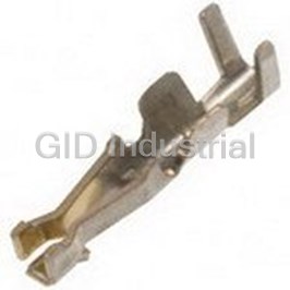
Datasheet

Extracted Text
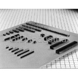
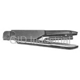
The product information in this catalog is for reference only. Please request the Engineering Drawing for the most current and accurate design information. All non-RoHS products have been discontinued, or will be discontinued soon. Please check the products status on the Hirose website RoHS search at www.hirose-connectors.com, or contact your Hirose sales representative. Ribbon Cable connector Compliant with MIL Standard HIF3B Series Features 1. Product Compliant with MIL Standard HIF3B series has been developed as a product compliant with MIL standard, and used for wide applications. 2. UL Approval Product HIF3B series connectors are UL approved. 3. Mechanism to Prevent Mis-insertion This connector is equipped with the mechanism to prevent Mis- insertion as follows. 1 The system provides the convex area to insert the guide-key on the pin header side, and to guide it in combination with the socket convex area (MIL standard). 2 The system embeds and guides the polarizing key in the socket holes. 4. Applicable Cable AWG#28 The applicable cable is UL2651 AWG#28 flat cable (7 cores./ 0.127mm, jacket dia. 0.9±0.1mm). Product Specifications ( ) ( ) Current rating : 1A Operating Temperature Range : –55 to +85ç Note 1 Storage Temperature Range : –10 to +60ç Note 2 Rating ( ) Voltage rating : 200V AC Operating Moisture Range : 40 to 80% Storage Humidity Range : 40 to 70% Note 2 Item Specification Condition 1. Insulation Resistance 1000M ohms min. 500V DC 2. Withstanding voltage No flashover or insulation breakdown. 650V AC/1 minute 3. Contact Resistance 15m ohms max. 0.1A 4. Vibration No electrical discontinuity of 1µs or more Frequency: 10 to 55 Hz, single amplitude of 0.75 mm, 2 hours in each of the 3 directions. 5. Humidity (Steady state) Insulation resistance: 1000M ohms min. 96 hours at temperature of 40ç and humidity of 90% to 95% (-65ç: 30 minutes ➝ 15 to 35ç: 5 minutes max. 6. Temperature Cycle No damage, cracks, or parts looseness. 125ç: 30 minutes ➝15 to 35ç: 5 minutes max.) 5 cycles 7. Durability (Mating/un-mating) Contact resistance: 15m ohms max. 500 cycles Flow: 260ç for 10 seconds 8. Resistance to Soldering heat No deformation of components affecting performance. Manual soldering: 300ç for 3 seconds Note 1: Includes temperature rise caused by current flow. Note 2: The term "storage" refers to products stored for long period of time prior to mounting and use. Operating Temperature Range and Humidity range covers non conducting condition of installed connectors in storage, shipment or during transportation. Material Part Material Finish Remarks Insulator PBT Black UL94V-0 Connection area Gold plated D Beryllium copper Connection area Gold plated Socket Contact ––––––– Connection area Gold plated DA Copper alloy Connection area Tin lead plated Pin header contact Brass Selective Gold plated ––––––– B15 The product information in this catalog is for reference only. Please request the Engineering Drawing for the most current and accurate design information. All non-RoHS products have been discontinued, or will be discontinued soon. Please check the products status on the Hirose website RoHS search at www.hirose-connectors.com, or contact your Hirose sales representative. Ordering Information Socket HIF 3B - * D A - 2.54 R qw et r y u q Series Name : HIF ( ) w Series No. : 3B, 3BA, 3BB 50, 60, 64 contacts only e Number of contacts : 16, 20, 26, 30, 34, 40, 50, 60, 64 r Contact alignment : D : Double t A : VA type y Contact pitch : 2.54mm u Connection type R : ID type Pin Header HIF 3B - * P A - 2.54 DS qw et r y u q Series Name : HIF w Series No. : 3B : (14 contacts not included) 3BC: (10 contacts only) 3BA, 3BB: (50, 60, 64 contacts only) 3BD: (10 contacts only) e Number of contacts : 16, 20, 26, 30, 34, 40, 50, 60, 64 r P : Pin header t A : Selective gold plated y Contact pitch : 2.54mm u Contact style DS : Right angle type DSA : Straight type B16 The product information in this catalog is for reference only. Please request the Engineering Drawing for the most current and accurate design information. All non-RoHS products have been discontinued, or will be discontinued soon. Please check the products status on the Hirose website RoHS search at www.hirose-connectors.com, or contact your Hirose sales representative. Socket (With guide to prevent mis-insertion) Body Protector Clamp Note1, Note2: The number of polarizing keys and polarizing keyways changes according to products. Refer to the list as shown below. Note3: The 50, 60 and 64 contact connector contain two types of polarizing guides. Use the products, referring to Notes 1 and 2. Note4: The 6 contact has no polarizing mark. Unit:mm Polarizing Guide Polarizing Keyway Part Number CL No. Part Number CL No. Number of Contacts A B C D (Note 1) (Note 2) HIF3BA- 6D-2.54R 610-0032-3 6 12.19 5.08 6.35 7.72 ––––––– None HIF3BA-10D-2.54R 610-0021-7 HIF3BA-10DA-2.54R 610-0651-5 10 17.27 10.16 11.43 12.8 One on left side HIF3BA-14D-2.54R 610-0022-0 HIF3BA-14DA-2.54R 610-0652-8 14 22.35 15.24 16.51 17.88 HIF3BA-16D-2.54R 610-0023-2 HIF3BA-16DA-2.54R 610-0653-0 16 24.89 17.78 19.05 20.42 HIF3BA-20D-2.54R 610-0024-5 HIF3BA-20DA-2.54R 610-0654-3 20 29.97 22.86 24.13 25.5 One at center HIF3BA-26D-2.54R 610-0025-8 HIF3BA-26DA-2.54R 610-0655-6 26 37.59 30.48 31.75 33.12 HIF3BA-30D-2.54R 610-0026-0 HIF3BA-30DA-2.54R 610-0656-9 30 42.67 35.56 36.83 38.2 HIF3BA-34D-2.54R 610-0027-3 HIF3BA-34DA-2.54R 610-0657-1 34 47.75 40.64 41.91 43.28 HIF3BA-40D-2.54R 610-0028-6 HIF3BA-40DA-2.54R 610-0658-4 40 55.37 48.26 49.53 50.9 One on right and HIF3BA-50D-2.54R 610-0029-9 HIF3BA-50DA-2.54R 610-0659-7 50 68.07 60.96 62.23 63.6 One on right and left sides, resp. left sides, resp. HIF3BB-50D-2.54R 610-0041-4 HIF3BB-50DA-2.54R 610-0671-2 50 68.07 60.96 62.23 63.6 One at center HIF3BA-60D-2.54R 610-0030-8 HIF3BA-60DA-2.54R 610-0660-6 60 80.77 73.66 74.93 76.3 One on right and left sides, resp. HIF3BB-60D-2.54R 610-0042-7 HIF3BB-60DA-2.54R 610-0672-5 60 80.77 73.66 74.93 76.3 One at center HIF3BA-64D-2.54R 610-0031-0 HIF3BA-64DA-2.54R 610-0661-9 64 85.85 78.74 80.01 81.38 One on right and left sides, resp. HIF3BB-64D-2.54R 610-0043-0 HIF3BB-64DA-2.54R 610-0673-8 64 85.85 78.74 80.01 81.38 One at center The products marked with comply with MIL standard. B17 The product information in this catalog is for reference only. Please request the Engineering Drawing for the most current and accurate design information. All non-RoHS products have been discontinued, or will be discontinued soon. Please check the products status on the Hirose website RoHS search at www.hirose-connectors.com, or contact your Hirose sales representative. Socket with Withdrawal Tab Unit : mm Part Number CL No. Number of Contacts A B HIF3BA-10D-2.54R-CL 610-0190-4 10 17.27 5.3 HIF3BA-16D-2.54R-CL 610-0192-0 16 24.89 12.9 HIF3BA-20D-2.54R-CL 610-0193-2 20 29.97 18.0 HIF3BA-26D-2.54R-CL 610-0194-5 26 37.59 25.5 HIF3BA-30D-2.54R-CL 610-0195-8 30 42.67 30.5 HIF3BA-34D-2.54R-CL 610-0196-0 34 47.75 35.8 HIF3BA-40D-2.54R-CL 610-0197-3 40 55.37 43.4 HIF3BA-50D-2.54R-CL 610-0198-6 50 68.07 56.0 HIF3BB-50D-2.54R-CL 610-0201-9 HIF3BA-60D-2.54R-CL 610-0199-9 60 80.77 68.5 HIF3BB-60D-2.54R-CL 610-0202-1 HIF3BA-64D-2.54R-CL 610-0200-6 64 85.85 73.8 HIF3BB-64D-2.54R-CL 610-0203-4 B18 The product information in this catalog is for reference only. Please request the Engineering Drawing for the most current and accurate design information. All non-RoHS products have been discontinued, or will be discontinued soon. Please check the products status on the Hirose website RoHS search at www.hirose-connectors.com, or contact your Hirose sales representative. Socket Body Protector Clamp Note1: The number of polarizing keys and polarizing keyways changes according to products. For details, refer to the list as shown below. Note2: The 6 contact has no polarizing mark. Unit:mm Polarizing Guide Part Number CL No. Number of Contacts A B C D (Note 1) HIF3B- 6D-2.54R 610-0012-6 6 12.19 5.08 6.35 7.72 None HIF3B-10D-2.54R 610-0001-0 10 17.27 10.16 11.43 12.80 One on left side HIF3B-14D-2.54R 610-0002-2 14 22.35 15.24 16.51 17.88 HIF3B-16D-2.54R 610-0003-5 16 24.89 17.78 19.05 20.42 HIF3B-20D-2.54R 610-0004-8 20 29.97 22.86 24.13 25.50 HIF3B-26D-2.54R 610-0005-0 26 37.59 30.48 31.75 33.12 HIF3B-30D-2.54R 610-0006-3 30 42.67 35.56 36.83 38.2 One on right and HIF3B-34D-2.54R 610-0007-6 34 47.75 40.64 41.91 43.28 left sides, resp. HIF3B-40D-2.54R 610-0008-9 40 55.37 48.26 49.53 50.90 HIF3B-50D-2.54R 610-0009-1 50 68.07 60.96 62.23 63.6 HIF3B-60D-2.54R 610-0010-0 60 80.77 73.66 74.93 76.3 HIF3B-64D-2.54R 610-0011-3 64 85.85 78.74 80.01 81.38 The products marked with comply with MIL standard. B19 The product information in this catalog is for reference only. Please request the Engineering Drawing for the most current and accurate design information. All non-RoHS products have been discontinued, or will be discontinued soon. Please check the products status on the Hirose website RoHS search at www.hirose-connectors.com, or contact your Hirose sales representative. Four Wall Angle Through hole BPCB mounting pattern Note 1, Note 2: The number of polarizing slot and key installed positions changes according to products. Refer to the list as shown below. Note 3: The spacer moves to the right according to the number of contacts. Note 4: The 10, 50, 60 and 64 contact connectors contain two types of n=number of contacts polarizing slots. Use products, referring to (Note 1) (Note 2). Unit:mm Polarizing Slot Polarizing Key Install Part Number CL No. Number of Contacts A B C D E F (Note 1) (Note 2) 28.14 HIF3BA-10PA-2.54DS 610-0091-2 10 32.0 17.5 10.16 21.8 27.9 None One on right side MAX51.1 28.14 HIF3BD-10PA-2.54DS 610-0171-0 10 32.0 17.5 10.16 21.8 27.9 None MAX51.1 33.24 HIF3BA-14PA-2.54DS 610-0092-5 14 37.1 22.6 15.24 26.9 33.0 One on right side MAX56.2 35.74 HIF3BA-16PA-2.54DS 610-0093-8 16 39.6 25.1 17.78 29.5 35.5 MAX58.7 40.84 HIF3BA-20PA-2.54DS 610-0094-0 20 44.7 30.2 22.86 34.5 40.6 MAX63.8 One at center 48.44 HIF3BA-26PA-2.54DS 610-0095-3 26 52.3 37.8 30.48 42.2 48.3 MAX71.4 53.54 HIF3BA-30PA-2.54DS 610-0096-6 30 57.4 42.9 35.56 47.2 53.3 MAX76.5 58.64 HIF3BA-34PA-2.54DS 610-0097-9 34 62.5 48.0 40.64 52.3 58.4 MAX81.6 66.24 HIF3BA-40PA-2.54DS 610-0098-1 40 70.1 55.6 48.26 59.9 66.0 MAX89.2 One on right and 78.94 HIF3BA-50PA-2.54DS 610-0099-4 50 82.8 68.3 60.96 72.6 78.7 One on right and left sides, resp. left sides, resp. MAX101.9 78.94 HIF3BB-50PA-2.54DS 610-0131-5 50 82.8 68.3 60.96 72.6 78.7 One at center MAX101.9 91.64 HIF3BA-60PA-2.54DS 610-0100-1 60 95.5 81.0 73.66 85.3 91.4 One on right and left sides, resp. MAX114.6 91.64 HIF3BB-60PA-2.54DS 610-0132-8 60 95.5 81.0 73.66 85.3 91.4 One at center MAX114.6 96.74 HIF3BA-64PA-2.54DS 610-0101-4 64 100.6 86.1 78.74 90.4 96.5 One on right and left sides, resp. MAX119.7 96.74 HIF3BB-64PA-2.54DS 610-0133-0 64 100.6 86.1 78.74 90.4 96.5 One at center MAX119.7 The products marked with comply with MIL standard. B20 The product information in this catalog is for reference only. Please request the Engineering Drawing for the most current and accurate design information. All non-RoHS products have been discontinued, or will be discontinued soon. Please check the products status on the Hirose website RoHS search at www.hirose-connectors.com, or contact your Hirose sales representative. Four-Wall Straight Through hole BPCB mounting pattern Note 1, Note 2: The number of polarizing slot and key installed positions changes according to products. Refer to the list as shown below. Note 3: The spacer moves to the right according to the number of contacts. n=number of contactsNote 4: The 10, 50, 60 and 64 contact connectors contain two types of polarizing slots. Use products, confirming (Note 1) (Note 2). Note 5: The 6 contact has no polarity mark. Unit:mm Polarizing Slot Polarizing Key Install Part Number CL No. Number of Contacts A B C D E F (Note 1) (Note 2) 23.06 HIF3-6PA-2.54DSA 562-0503-9 6 26.92 12.42 05.08 16.7 22.82 One at center None MAX46.02 28.14 HIF3BA-10PA-2.54DSA 610-0111-8 10 32.0 17.5 10.16 21.8 27.9 None One on right side MAX51.1 28.14 HIF3BD-10PA-2.54DSA 610-0181-3 10 32.0 17.5 10.16 21.8 27.9 None MAX51.1 33.24 37.1 22.6 26.9 33.0 HIF3BA-14PA-2.54DSA 610-0112-0 14 15.24 One on right side MAX56.2 35.74 39.6 25.1 29.5 35.5 HIF3BA-16PA-2.54DSA 610-0113-3 16 17.78 MAX58.7 40.84 HIF3BA-20PA-2.54DSA 610-0114-6 20 44.7 30.2 22.86 34.5 40.6 MAX63.8 One at center 48.44 HIF3BA-26PA-2.54DSA 610-0115-9 26 52.3 37.8 30.48 42.2 48.3 MAX71.4 53.54 HIF3BA-30PA-2.54DSA 610-0116-1 30 57.4 42.9 35.56 47.2 53.3 MAX76.5 58.64 HIF3BA-34PA-2.54DSA 610-0117-4 34 62.5 48.0 40.64 52.3 58.4 MAX81.6 66.24 70.1 55.6 59.9 66.0 HIF3BA-40PA-2.54DSA 610-0118-7 40 48.26 MAX89.2 One on right and 78.94 82.8 68.3 72.6 78.7 HIF3BA-50PA-2.54DSA 610-0119-0 50 60.96 One on right and left sides, resp. left sides, resp. MAX101.9 78.94 HIF3BB-50PA-2.54DSA 610-0141-9 50 82.8 68.3 60.96 72.6 78.7 One at center MAX101.9 91.64 HIF3BA-60PA-2.54DSA 610-0120-9 60 95.5 81.0 73.66 85.3 91.4 One on right and left sides, resp. MAX114.6 91.64 HIF3BB-60PA-2.54DSA 610-0142-1 60 95.5 81.0 73.66 85.3 91.4 One at center MAX114.6 96.74 HIF3BA-64PA-2.54DSA 610-0121-1 64 100.6 86.1 78.74 90.4 96.5 One on right and left sides, resp. MAX119.7 96.74 100.6 86.1 90.4 96.5 HIF3BB-64PA-2.54DSA 610-0143-4 64 78.74 One at center MAX119.7 The products marked with comply with MIL standard. B21 The product information in this catalog is for reference only. Please request the Engineering Drawing for the most current and accurate design information. All non-RoHS products have been discontinued, or will be discontinued soon. Please check the products status on the Hirose website RoHS search at www.hirose-connectors.com, or contact your Hirose sales representative. Three Wall Angle Type BPCB mounting pattern Note 1, Note 2: The number of polarizing slot and key installed positions changes according to products. Refer to the list as shown below. Note 3: The spacer moves according to the number of contacts. Note 4: The 10 contact connector consists of two types. Use products, confirming (Note 1) (Note 2). n=number of contacts Note 5: The 6 contact has no polarity mark. Note 6: The nut built-in specification product is also provided. The product can be fixed by M2 screws from the rear side. Use the screw of (board thickness) +4 mm under the neck. Unit:mm Polarizing Slot Polarizing Key Install Part Number CL No. Number of Contacts A B C D E F (Note 1) (Note 2) 28.14 HIF3BD-10PA-2.54DS 610-0051-8 10 32.0 17.5 10.16 21.8 27.9 None One on right side MAX51.1 28.14 HIF3BC-10PA-2.54DS 610-0151-2 10 32.0 17.5 10.16 21.8 27.9 None MAX51.1 35.74 HIF3BD-16PA-2.54DS 610-0052-0 16 39.6 25.1 17.78 29.5 35.5 MAX58.7 40.84 HIF3BD-20PA-2.54DS 610-0053-3 20 44.7 30.2 22.86 34.5 40.6 MAX63.8 48.44 HIF3BD-26PA-2.54DS 610-0054-6 26 52.3 37.8 30.48 42.2 48.3 One at center MAX71.4 53.54 HIF3BD-30PA-2.54DS 610-0055-9 30 57.4 42.9 35.56 47.2 53.3 MAX76.5 One on right and 58.64 HIF3BD-34PA-2.54DS 610-0056-1 34 62.5 48.0 40.64 52.3 58.4 left sides, resp. MAX81.6 66.24 HIF3BD-40PA-2.54DS 610-0057-4 40 70.1 55.6 48.26 59.9 66.0 MAX89.2 78.94 HIF3BD-50PA-2.54DS 610-0058-7 50 82.8 68.3 60.96 72.6 78.7 MAX101.9 91.64 HIF3BD-60PA-2.54DS 610-0059-0 60 95.5 81.0 73.66 85.3 91.4 One on right and left sides, resp. MAX114.6 96.74 HIF3BD-64PA-2.54DS 610-0060-9 64 100.6 86.1 78.74 90.4 96.5 MAX119.7 The products marked with comply with MIL standard. B22 The product information in this catalog is for reference only. Please request the Engineering Drawing for the most current and accurate design information. All non-RoHS products have been discontinued, or will be discontinued soon. Please check the products status on the Hirose website RoHS search at www.hirose-connectors.com, or contact your Hirose sales representative. Three Wall Straight Through hole BPCB mounting pattern Note1,Note2: The number of polarizing slot and key installed positions changes according to products. Refer to the list as shown n=number of contacts below. Note3: The spacer moves to the right according to the number of contacts. Note4: The 10 contact connector consists of two types. Use products, referring to (Note 1) and (Note 2). Note5: The 6 contact has no polarity mark. Unit:mm Polarizing Slot Polarizing Key Install Part Number CL No. Number of Contacts A B C D E F (Note 1) (Note 2) 28.14 HIF3BD-10PA-2.54DSA 610-0071-5 10 32.0 17.5 10.16 21.8 27.9 None One on right side MAX51.1 28.14 HIF3BC-10PA-2.54DSA 610-0161-6 10 32.0 17.5 10.16 21.8 27.9 None MAX51.1 35.74 HIF3BD-16PA-2.54DSA 610-0072-8 16 39.6 25.1 17.78 29.5 35.5 MAX58.7 40.84 HIF3BD-20PA-2.54DSA 610-0073-0 20 44.7 30.2 22.86 34.5 40.6 MAX63.8 48.44 HIF3BD-26PA-2.54DSA 610-0074-3 26 52.3 37.8 30.48 42.2 48.3 One at center MAX71.4 53.54 HIF3BD-30PA-2.54DSA 610-0075-6 30 57.4 42.9 35.56 47.2 53.3 MAX76.5 One on right and 58.64 HIF3BD-34PA-2.54DSA 610-0076-9 34 62.5 48.0 40.64 52.3 58.4 left sides, resp. MAX81.6 66.24 HIF3BD-40PA-2.54DSA 610-0077-1 40 70.1 55.6 48.26 59.9 66.0 MAX89.2 78.94 HIF3BD-50PA-2.54DSA 610-0078-4 50 82.8 68.3 60.96 72.6 78.7 MAX101.9 91.64 HIF3BD-60PA-2.54DSA 610-0079-7 60 95.5 81.0 73.66 85.3 91.4 One on right and left sides, resp. MAX114.6 96.74 HIF3BD-64PA-2.54DSA 610-0080-6 64 100.6 86.1 78.74 90.4 96.5 MAX119.7 The products marked with comply with MIL standard. B23 The product information in this catalog is for reference only. Please request the Engineering Drawing for the most current and accurate design information. All non-RoHS products have been discontinued, or will be discontinued soon. Please check the products status on the Hirose website RoHS search at www.hirose-connectors.com, or contact your Hirose sales representative. Four Wall Wrapping Type BPCB mounting pattern Note 1, Note 2. The number of polarizing slot and key installed positions changes according to products. Refer to the list as shown below. Note 3. The spacer moves to the right according to the number of contacts. n=number of contactsNote 4. The 10, 50, 60 and 64 contact connectors consists of two types. Use products, confirming (Note 1) (Note 2). Note 5. The mark * indicates the number of contacts. Note 6. The nut built-in specification product is also provided. The product can be fixed by M2 screws from the rear side. Use the screw of (board thickness) +4 mm under the neck. Unit:mm Polarizing Slot Polarizing Key Install Part Number CL No. Number of Contacts A B C D E F (Note 1) (Note 2) 28.14 HIF3BA-10P-2.54W 610-0503-8 10 32.0 17.5 10.16 21.8 27.9 None One on right side MAX51.1 28.14 HIF3BD-10P-2.54W 610-0492-3 10 32.0 17.5 10.16 21.8 27.9 None MAX51.1 33.24 HIF3BA-14P-2.54W 610-0493-6 14 37.1 22.6 15.24 26.9 33.0 One on right side MAX56.2 35.74 HIF3BA-16P-2.54W 610-0494-9 16 39.6 25.1 17.78 29.5 35.5 MAX58.7 40.84 HIF3BA-20P-2.54W 610-0495-1 20 44.7 30.2 22.86 34.5 40.6 MAX63.8 One at center 48.44 HIF3BA-26P-2.54W 610-0496-4 26 52.3 37.8 30.48 42.2 48.3 MAX71.4 53.54 HIF3BA-30P-2.54W 610-0497-7 30 57.4 42.9 35.56 47.2 53.3 MAX76.5 58.64 HIF3BA-34P-2.54W 610-0498-0 34 62.5 48.0 40.64 52.3 58.4 MAX81.6 66.24 HIF3BA-40P-2.54W 610-0499-2 40 70.1 55.6 48.26 59.9 66.0 MAX89.2 One on right and 78.94 HIF3BA-50P-2.54W 610-0504-0 50 82.8 68.3 60.96 72.6 78.7 One on right and left sides, resp. left sides, resp. MAX101.9 78.94 HIF3BB-50P-2.54W 610-0500-0 50 82.8 68.3 60.96 72.6 78.7 One at center MAX101.9 91.64 HIF3BA-60P-2.54W 610-0505-3 60 95.5 81.0 73.66 85.3 91.4 One on right and left sides, resp. MAX114.6 91.64 HIF3BB-60P-2.54W 610-0501-2 60 95.5 81.0 73.66 85.3 91.4 One at center MAX114.6 96.74 HIF3BA-64P-2.54W 610-0506-6 64 100.6 86.1 78.74 90.4 96.5 One on right and left sides, resp. MAX119.7 96.74 HIF3BB-64P-2.54W 610-0502-5 64 100.6 86.1 78.74 90.4 96.5 One at center MAX119.7 The products marked with comply with MIL standard. B24 The product information in this catalog is for reference only. Please request the Engineering Drawing for the most current and accurate design information. All non-RoHS products have been discontinued, or will be discontinued soon. Please check the products status on the Hirose website RoHS search at www.hirose-connectors.com, or contact your Hirose sales representative. Four Wall Straight Through hole [ ] Flux Blister Prevention Type BPCB mounting pattern Note1: The number of polarizing slot and key installed positions changes according to products. Refer to the list as shown below. n=number of contacts Unit:mm Part Number CL No. Number of Contacts A B C D E F Polarizing Slot Polarizing Key Install 28.14 HIF3CA-10PA-2.54DSA 610-0701-1 10 32.0 17.5 10.16 21.8 27.9 None One on right side MAX51.1 28.14 HIF3CD-10PA-2.54DSA 610-0722-1 10 32.0 17.5 10.16 21.8 27.9 None MAX51.1 35.74 HIF3CA-16PA-2.54DSA 610-0703-7 16 39.6 25.1 17.78 29.5 35.5 MAX58.7 40.84 HIF3CA-20PA-2.54DSA 610-0704-0 20 44.7 30.2 22.86 34.5 40.6 MAX63.8 48.44 HIF3CA-26PA-2.54DSA 610-0705-2 26 52.3 37.8 30.48 42.2 48.3 One at center MAX71.4 53.54 HIF3CA-30PA-2.54DSA 610-0706-5 30 57.4 42.9 35.56 47.2 53.3 MAX76.5 58.64 HIF3CA-34PA-2.54DSA 610-0707-8 34 62.5 48.0 40.64 52.3 58.4 MAX81.6 One on right and 66.24 HIF3CA-40PA-2.54DSA 610-0708-0 40 70.1 55.6 48.26 59.9 66.0 left sides, resp. MAX89.2 78.94 HIF3CA-50PA-2.54DSA 610-0709-3 50 82.8 68.3 60.96 72.6 78.7 One on right and left sides, resp. MAX101.9 78.94 HIF3CB-50PA-2.54DSA 610-0721-9 50 82.8 68.3 60.96 72.6 78.7 MAX101.9 91.64 HIF3CB-60PA-2.54DSA 610-0723-4 60 95.5 81.0 73.66 85.3 91.4 One at center MAX114.6 96.74 HIF3CB-64PA-2.54DSA 610-0724-7 64 100.6 86.1 78.74 90.4 96.5 MAX119.7 The products marked with comply with MIL standard. B25 The product information in this catalog is for reference only. Please request the Engineering Drawing for the most current and accurate design information. All non-RoHS products have been discontinued, or will be discontinued soon. Please check the products status on the Hirose website RoHS search at www.hirose-connectors.com, or contact your Hirose sales representative. Two Stage Staking Right Angle Through hole Note 1, Note 2: The number of polarizing slot and key installed positions changes according to products. Refer to the list as shown below. Note 3: The spacer moves to the right according to the number of contacts. Note 4: The 10, 50, 60 and 64 contact connectors consists of two types. Use products, confirming (Note 1) (Note 2). Note 5: The mark * ndicates the number of contacts. Note 6: The locator is located optionally. Unit:mm Polarizing Slot Polarizing Key Install Part Number CL No. Number of Contacts A B C D E F (Note 1) (Note 2) 28.14 HIF3BA-10PA-2.54WB 610-1502-0 10 32.0 17.5 10.16 21.8 27.9 None One on right side MAX51.1 28.14 HIF3BD-10PA-2.54WB 610-1503-3 10 32.0 17.5 10.16 21.8 27.9 None MAX51.1 35.74 HIF3BA-16PA-2.54WB 610-1505-9 16 39.6 25.1 17.78 29.5 35.5 MAX58.7 40.84 HIF3BA-20PA-2.54WB 610-1506-1 20 44.7 30.2 22.86 34.5 40.6 MAX63.8 48.44 HIF3BA-26PA-2.54WB 610-1507-4 26 52.3 37.8 30.48 42.2 48.3 One at center MAX71.4 53.54 HIF3BA-30PA-2.54WB 610-1508-7 30 57.4 42.9 35.56 47.2 53.3 MAX76.5 58.64 HIF3BA-34PA-2.54WB 610-1509-0 34 62.5 48.0 40.64 52.3 58.4 MAX81.6 66.24 HIF3BA-40PA-2.54WB 610-1510-9 40 70.1 55.6 48.26 59.9 66.0 MAX89.2 One on right and 78.94 HIF3BA-50PA-2.54WB 610-1511-1 50 82.8 68.3 60.96 72.6 78.7 One on right and left sides, resp. left sides, resp. MAX101.9 78.94 HIF3BB-50PA-2.54WB 610-1512-4 50 82.8 68.3 60.96 72.6 78.7 One at center MAX101.9 91.64 HIF3BA-60PA-2.54WB 610-1513-7 60 95.5 81.0 73.66 85.3 91.4 One on right and left sides, resp. MAX114.6 91.64 HIF3BB-60PA-2.54WB 610-1514-0 60 95.5 81.0 73.66 85.3 91.4 One at center MAX114.6 96.74 HIF3BA-64PA-2.54WB 610-1515-2 64 100.6 86.1 78.74 90.4 96.5 One on right and left sides, resp. MAX119.7 96.74 HIF3BB-64PA-2.54WB 610-1516-5 64 100.6 86.1 78.74 90.4 96.5 One at center MAX119.7 The products marked with comply with MIL standard. B26 The product information in this catalog is for reference only. Please request the Engineering Drawing for the most current and accurate design information. All non-RoHS products have been discontinued, or will be discontinued soon. Please check the products status on the Hirose website RoHS search at www.hirose-connectors.com, or contact your Hirose sales representative. BCombination Pattern Note : Fix the HIF3-mounting hole spacer by screws between upper stage and lower stage connectors. BPCB mounting pattern Mounting Hole Spacer Part Number CL No. Finish HIF-3 mounting hole spacer 562-0714-4 PBT Black Note : 2 pieces are contained in a bag. B27 The product information in this catalog is for reference only. Please request the Engineering Drawing for the most current and accurate design information. All non-RoHS products have been discontinued, or will be discontinued soon. Please check the products status on the Hirose website RoHS search at www.hirose-connectors.com, or contact your Hirose sales representative. BPolarizing Key HIF3B-GK CL562-0601-8 HIF3-GPIN(A) HIF3BA-GPIN Note1: One unit of this Note1: One unit of this product is a set of five product is a set of five pieces in conjunction pieces in conjunction with a runner. The unit with a runner. The unit for sale is defined one for sale is defined one pack containing 20 pack containing 20 pieces. pieces. Note2: This product is Note2: This product is applicable to HIF3A- applicable to the *D2.54R, HIF3C- HIF3BA-*D2.54R *D2.54C and product. HIF3BA-*D2.54C products. Part Number CL No. Material Remarks Part Number CL No. Material Remarks HIF3BA-GPIN 612-0500-2 Poly acetal (white) HIF3-GPIN(A) 562-0126-6 Poly acetal (white) A set of 5 pieces A set of 5 pieces B28 The product information in this catalog is for reference only. Please request the Engineering Drawing for the most current and accurate design information. All non-RoHS products have been discontinued, or will be discontinued soon. Please check the products status on the Hirose website RoHS search at www.hirose-connectors.com, or contact your Hirose sales representative. BHIF3-Multi Clamp BHIF3-*CL Pull Tab This clamp is used for intermediate connection in the This pull tab is used for the HIF3 series equipped with cable clamp bus-line system, etc. Remove compulsory force from the function. Remove all compulsory force, which is loaded on the insulation displacement area of the connector in insulation displacement area of the connector for extraction. * Pull Tab can not be used for HIF3BA-*PD. intermediate connection. Note: This HIF3- Note: The pin header corresponds to the HIF3BAE Note: The pin header corresponds to the HIF3BAE series (lock E). series (lock E). BLock Low Profile Lock Pin Header F Type Lock Pin Header Lock G Lock F Part Number : HIF3BAG-**PA-2.54DSA Part Number : HIF3BAG-**PA-2.54DSA Low profile type, and used for lock ejection.Locking range more reduced than conventional lock type. Connector height is reduced. Even if connectors are aligned laterally, the mounting Since no connector clamp is needed on the cable side, space is reduced. this is used without turning back on the cable side. Take Note : The clamp must be replaced for HIF3A socket type care about this point. 50 contacts only. Take care about this point. B29 21.5 27.3 The product information in this catalog is for reference only. Please request the Engineering Drawing for the most current and accurate design information. All non-RoHS products have been discontinued, or will be discontinued soon. Please check the products status on the Hirose website RoHS search at www.hirose-connectors.com, or contact your Hirose sales representative. Socket for Crimping Unit: mm Part Number CL No. Number of Contacts A B Polarizing Guide HIF3BA-10D-2.54C 610-1041-0 10 17.25 10.16 HIF3BA-14D-2.54C 610-1051-3 14 22.35 15.24 HIF3BA-16D-2.54C 610-1042-2 16 24.8 17.78 HIF3BA-20D-2.54C 610-1043-5 20 29.95 22.86 One at center HIF3BA-26D-2.54C 610-1044-8 26 37.55 30.48 HIF3BA-30D-2.54C 610-1045-0 30 42.63 35.56 HIF3BA-34D-2.54C 610-1046-3 34 47.75 40.64 HIF3BA-40D-2.54C 610-1047-6 40 55.35 48.26 HIF3BA-50D-2.54C 610-1048-9 One right and left side, resp. 60.96 50 68.04 HIF3BB-50D-2.54C 610-1061-7 One at center HIF3BA-60D-2.54C 610-1049-1 One right and left side, resp. 60 80.77 73.66 HIF3BB-60D-2.54C 610-1062-0 One at center HIF3BA-64D-2.54C 610-1064-5 One right and left side, resp. 78.74 64 85.85 HIF3BB-64D-2.54C 610-1063-2 One at center B30 The product information in this catalog is for reference only. Please request the Engineering Drawing for the most current and accurate design information. All non-RoHS products have been discontinued, or will be discontinued soon. Please check the products status on the Hirose website RoHS search at www.hirose-connectors.com, or contact your Hirose sales representative. Cover Case for Crimping socket Unit: mm Part Number CL No. Number of Contacts A B C D E HIF3-20CV 562-0201-0 20 24.5 18.0 12.0 30.5 29.95 HIF3-26CV 562-0202-2 26 30.2 20.0 14.0 32.0 37.55 HIF3-30CV 562-0203-5 30 32.2 22.0 16.0 33.0 42.63 HIF3-34CV 562-0204-8 34 34.2 24.0 18.0 33.5 47.75 HIF3-40CV 562-0205-0 40 36.2 26.0 20.0 35.5 55.35 HIF3-50CV 562-0206-3 50 39.2 29.0 23.0 38.0 68.04 HIF3-60CV 562-0207-6 60 42.2 32.0 26.0 40.5 80.77 Note: The type F lock pin header cannot be used for a mating member. B31 The product information in this catalog is for reference only. Please request the Engineering Drawing for the most current and accurate design information. All non-RoHS products have been discontinued, or will be discontinued soon. Please check the products status on the Hirose website RoHS search at www.hirose-connectors.com, or contact your Hirose sales representative. Contact for Crimping Socket HIF3-2226SC 562-0079-8 gold plated contact in bag HIF3-2428SC 562-0124-0 gold plated contact in bag HIF3-2022SC 562-0492-4 gold plated contact in bag HIF3-2226SCA 562-0244-2 Selective gold plated contact in bag HIF3-2428SCA 562-0246-8 Selective gold plated contact in bag Applicable cable AWG#20 to #22 UL 1007 Stranded wire Applicable cable AWG#22 to #26 UL 1007 Stranded wire Applicable cable AWG#24 to #28 UL 1007 Stranded wire Manual crimping tool HIF3-TA2022HC Manual crimping tool HIF3-T2226HC Manual crimping tool HIF3-TA2428HC HIF3-2226SCF 562-0080-7 gold plated contact in reel HIF3-2428SCF 562-0125-3 gold plated contact in reel HIF3-2022SCF 562-0493-7 gold plated contact in reel ** HIF3-2226SCFA 562-0245-5 Selective gold plated contact in reel HIF3-2428SCFA 562-0247-0 Selective gold plated contact in reel Applicable cable AWG#20 to #22 UL 1007 Stranded wire Applicable cable AWG#22 to #26 UL 1007 Stranded wire Applicable cable AWG#24 to #28 UL 1007 Stranded wire Note:* products have both side careers. Type VA (Selective gold plated in reel) Part Number CL No. Applicable Cable A B C D E F AWG#22 to #26 UL 1007 Stranded wire 11.5 0.8 1.8 1.8 2.3 2.6 HIF3-2226SCFC 613-0002-1 AWG#26 to #30 UL 1007 Stranded wire 11.5 0.8 1.4 1.35 2.0 2.1 HIF3-2630SCFC 613-0001-9 AWG#32 to #36 UL 1007 Stranded wire 12.4 1.7 1.1 1.1 1.4 1.5 HIF3A-3236SCFC 613-0005-0 Type VA (Selective gold plated contact in bag) Part Number CL No. Applicable Cable Manual Crimp Tool A B C D E F HIF3-2226SCC 613-0004-7 AWG#22 to #26 UL 1007 Stranded wire HIF3-TB2226HC 11.5 0.8 1.8 1.8 2.3 2.6 HIF3-2630SCC 613-0003-4 AWG#26 to #30 UL 1007 Stranded wire HIF3-TB2630HC 11.5 0.8 1.4 1.35 2.0 2.1 B32 The product information in this catalog is for reference only. Please request the Engineering Drawing for the most current and accurate design information. All non-RoHS products have been discontinued, or will be discontinued soon. Please check the products status on the Hirose website RoHS search at www.hirose-connectors.com, or contact your Hirose sales representative. BTools Crimping Tool Part Number CL No. HIF3-T2226HC 550-0063-8 Manual Crimping Tool HIF3-T2226HC Automatic Crimping Tool (Type: CM-105) Part Number CL No. CM-105 901-0005-4 Contact Extraction Tools How to use the extraction tool (2) How to adjust the lance (raise) (1) How to extract contacts In order to re-insert the contact As shown in Figure 1, where the removed from the insulated case, extraction tool is inserted in the lance raise the contact lance area using the fixed slot on the insulated case, slightly tool A, and re-insert the contact, as pull the cable, and the contact can be shown in Figure 2. removed. Part Number CL No. HIF1-PO 550-0049-7 Figure 1 B33 The product information in this catalog is for reference only. Please request the Engineering Drawing for the most current and accurate design information. All non-RoHS products have been discontinued, or will be discontinued soon. Please check the products status on the Hirose website RoHS search at www.hirose-connectors.com, or contact your Hirose sales representative. Part Number CL No. Applicable Contact Applicable Cable Type Item Manual Manual crimping tool HIF3-2226SC HIF3-T2226HC 550-0063-8 AWG#22 to #26 HIF3-2226SCA HIF3-2428SC HIF3-TA2428HC 550-0100-2 AWG#24 to #28 HIF3-2428SCA HIF3-TA2022HC 550-0124-0 HIF3-2022SC AWG#20 to #22 HIF3-TB2226HC 550-0154-1 HIF3-2226SCC AWG#22 to #26 HIF3-TB2630HC 550-0155-4 AWG#26 to #30 HIF3-2630SCC Automatic Automatic crimping tool unit CM-105 901-0005-4 ––––––– ––––––– AWG#22 to #26 HIF3-2226SCF Applicator AP105-HIF3-22-28SCF 901-4031-6 HIF3-2428SCF AWG#24 to #28 (Note1) HIF3-2226SCFA AWG#22 to #26 AP105-HIF3-22-28SCFA 901-4030-3 HIF3-2428SCFA AWG#24 to #28 ( ) Note1 AP105-HIF3-2022S 901-4027-9 HIF3-2022SCF AWG#20 to #22 AP105-HIF3-2226SCFC 901-4005-6 HIF3-2226SCFC AWG#22 to #26 AP105-HIF3-2630SCFC 901-4006-9 HIF3-2630SCFC AWG#26 to #30 AP105-HIF3-3236SCFC 901-4007-1 HIF3-3236SCFC AWG#32 to #36 Extraction tool HIF1-PO 550-0049-7 ––––––– ––––––– Note1: AP106-HIF3-22-28SCF and AP105-HIF3-22-28CFA can be modified by changing a few parts. B34 The product information in this catalog is for reference only. Please request the Engineering Drawing for the most current and accurate design information. All non-RoHS products have been discontinued, or will be discontinued soon. Please check the products status on the Hirose website RoHS search at www.hirose-connectors.com, or contact your Hirose sales representative. BSocket Side (Crimping) Assembling Procedures (1) As shown in Figure 1, peel the applicable cable (AWG#20 to #26) jacket, and connect it using crimping jig HIF3-TA2022HC, HIF3-TA2226HC, or HIF3-TA2426HC. In this case, insert the cable so as to hit the contact cable stripper position as shown Figure 2. (2) After connection as shown Figure 2, check the contact direction, and insert the contact as shown Figures 3 and 4. Slightly pull the cable, and check whether the contact lance position is firmly fixed to the insulation case, as shown in the area (A). Note : For handling procedures for special crimping tools, refer to the "Handling Instruction Manual". Figure 1 Figure 2 Figure 3 Figure 4 B35 The product information in this catalog is for reference only. Please request the Engineering Drawing for the most current and accurate design information. All non-RoHS products have been discontinued, or will be discontinued soon. Please check the products status on the Hirose website RoHS search at www.hirose-connectors.com, or contact your Hirose sales representative. HIF3B Connection Circuit Diagram Type AB Type AD Type CD B36 Type CD Type AD Type AB The product information in this catalog is for reference only. Please request the Engineering Drawing for the most current and accurate design information. All non-RoHS products have been discontinued, or will be discontinued soon. Please check the products status on the Hirose website RoHS search at www.hirose-connectors.com, or contact your Hirose sales representative. Type AC Type CC Type AA B37 Type AA Type CC Type AC The product information in this catalog is for reference only. Please request the Engineering Drawing for the most current and accurate design information. All non-RoHS products have been discontinued, or will be discontinued soon. Please check the products status on the Hirose website RoHS search at www.hirose-connectors.com, or contact your Hirose sales representative. HIF2E R(S) A to HIF3B Connection Circuit Diagram Type AA Type AC B38 The product information in this catalog is for reference only. Please request the Engineering Drawing for the most current and accurate design information. All non-RoHS products have been discontinued, or will be discontinued soon. Please check the products status on the Hirose website RoHS search at www.hirose-connectors.com, or contact your Hirose sales representative. Type BA Type BC B39 The product information in this catalog is for reference only. Please request the Engineering Drawing for the most current and accurate design information. All non-RoHS products have been discontinued, or will be discontinued soon. Please check the products status on the Hirose website RoHS search at www.hirose-connectors.com, or contact your Hirose sales representative. HIF2E R(S)B to HIF3 Connection Circuit Diagram Type AA Type AC B40 The product information in this catalog is for reference only. Please request the Engineering Drawing for the most current and accurate design information. All non-RoHS products have been discontinued, or will be discontinued soon. Please check the products status on the Hirose website RoHS search at www.hirose-connectors.com, or contact your Hirose sales representative. Type BA Type BC B41
Frequently asked questions
How does Electronics Finder differ from its competitors?

Is there a warranty for the HIF3-2428SCFA?
Which carrier will Electronics Finder use to ship my parts?
Can I buy parts from Electronics Finder if I am outside the USA?
Which payment methods does Electronics Finder accept?
Why buy from GID?

Quality
We are industry veterans who take pride in our work

Protection
Avoid the dangers of risky trading in the gray market

Access
Our network of suppliers is ready and at your disposal

Savings
Maintain legacy systems to prevent costly downtime

Speed
Time is of the essence, and we are respectful of yours
Related Products
Contact SKT Crimp ST Cable Mount 22-26AWG Bag
Contact SKT Crimp ST Cable Mount Reel
Contact SKT Crimp ST Cable Mount 26-30AWG Bag
Contact SKT Crimp ST Cable Mount Reel
Contact SKT Crimp ST Cable Mount 26-30AWG Bag Automotive
Contact SKT Crimp ST Cable Mount 26-30AWG Reel Automotive
Request a Quote

The quote request has been received
Close

Facing challenges or have inquiries? Feel free to contact us!
Call Us +1-469-283-2440
What they say about us
FANTASTIC RESOURCE
One of our top priorities is maintaining our business with precision, and we are constantly looking for affiliates that can help us achieve our goal. With the aid of GID Industrial, our obsolete product management has never been more efficient. They have been a great resource to our company, and have quickly become a go-to supplier on our list!
Bucher Emhart Glass
EXCELLENT SERVICE
With our strict fundamentals and high expectations, we were surprised when we came across GID Industrial and their competitive pricing. When we approached them with our issue, they were incredibly confident in being able to provide us with a seamless solution at the best price for us. GID Industrial quickly understood our needs and provided us with excellent service, as well as fully tested product to ensure what we received would be the right fit for our company.
Fuji
HARD TO FIND A BETTER PROVIDER
Our company provides services to aid in the manufacture of technological products, such as semiconductors and flat panel displays, and often searching for distributors of obsolete product we require can waste time and money. Finding GID Industrial proved to be a great asset to our company, with cost effective solutions and superior knowledge on all of their materials, it’d be hard to find a better provider of obsolete or hard to find products.
Applied Materials
CONSISTENTLY DELIVERS QUALITY SOLUTIONS
Over the years, the equipment used in our company becomes discontinued, but they’re still of great use to us and our customers. Once these products are no longer available through the manufacturer, finding a reliable, quick supplier is a necessity, and luckily for us, GID Industrial has provided the most trustworthy, quality solutions to our obsolete component needs.
Nidec Vamco
TERRIFIC RESOURCE
This company has been a terrific help to us (I work for Trican Well Service) in sourcing the Micron Ram Memory we needed for our Siemens computers. Great service! And great pricing! I know when the product is shipping and when it will arrive, all the way through the ordering process.
Trican Well Service
GO TO SOURCE
When I can't find an obsolete part, I first call GID and they'll come up with my parts every time. Great customer service and follow up as well. Scott emails me from time to time to touch base and see if we're having trouble finding something.....which is often with our 25 yr old equipment.
ConAgra Foods