

 Manufacturers
HIROSE ELECTRIC USA, INC. IT1-PICKER(1)
Description
Extraction Tool
Part Number
IT1-PICKER(1)
Price
Request Quote
Manufacturer
HIROSE ELECTRIC USA, INC.
Lead Time
Request Quote
Category
Fasteners, Hardware and Fluid Transfer » Hardware Tools
Specifications
Manufacturer
Hirose Electric USA, Inc.
Manufacturers Part #
IT1-PICKER(1)
Lead Time
16 Week Lead Time
Industry Aliases
IT1-PICKER(1)
Sub-Category
Hardware Tools
Brand
HIROSE
Packaging
Bag
Factory Pack Quantity
2
Datasheet

Extracted Text
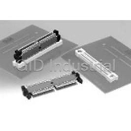
High Speed, Matched-Impedance, Parallel Board-to-board Connector
IT1 Series
Receptacle (2 required)
IT1 Series Outline
High-speed matched-impedance parallel board-to-board
connector designed for applications requiring board-to-
board spacing with transmission speeds exceeding
1GHz. The connection system has matched impedance
Transmission Module
of 50 ohm or can be customized. Contacts are on 0.5mm
pitch.
●Connection Cross-Sectional Diagram
■Features
1. Impedance Matching using a 4-Layer Board
The innovative transmission module uses PC boards
with a strip line design of transmission lines, providing
Receptacle
matched impedance of 50 ohms, for standard product.
2. Supports Multiple Connectors per board
Designed with a tolerance of +/- 0.2mm for both the X 2-Point contact
and Y-axis. The three-piece structure and the +/- 0.2mm
tolerance allows 3 or more IT1’s to be mounted on a
4-Layer board
(Impedance matching)
single board.
3. Customized Board-to-Board Distance
Board-to-board distance can be customized, from 16mm
Transmission Module
to 40mm.
Ground lines or additional traces can be added to
support high level, high speed transmission or mixed
2-Point contact
power/signal applications.
4. Signal to Ground Ratio
Receptacle
The standard signal-to-ground ratio is 10:2, which makes
reliable matching of the characteristic impedance of each
transmission line. This ratio also can be customized.
5. Contact Reliability
Use of double contact points on each of the contacts
■Applications
assures highly reliable performance.
Routers, servers, base stations and other
telecommunication equipment.
A294
Jun.1.2018 Copyright 2018 HIROSE ELECTRIC CO., LTD. All Rights Reserved.
(0.65) : Wipe
IT1 Series●High Speed, Matched-Impedance, Parallel Board-to-board Connector System
■Product Specifications
Current Operation Temperature Storage Temperature
+ +
-55ç to 85ç -10ç to 60ç (Note 2)
0.4 A (Note 1)
Range
rating Range
Rating
Storage Humidity
Voltage Operation Humidity Relative humidity 95% max.
50V AC 40% to 70% (Note 2)
rating Range (No condensation) Range
Item Specification Conditions
1. Insulation resistance 100 M ohms min. Measured at 100V DC
2. Withstanding voltage No flashover or insulation breakdown 150 V AC/one minute
3. Contact resistance 100 m ohms max. Measured at 100 mA
No electrical discontinuity of 1 μs or more. Frequency of 10 to 55 Hz, 0.75mm single amplitude, for 10
4. Vibration
No damage, cracks, or parts dislocation. cycles in each of 3 directions
2
No electrical discontinuity of 1 μs. min. Acceleration of 490 m/s , 11 ms duration, sine half-wave
5. Shock
No damage, cracks, or parts dislocation waveform, 3 cycles in each of the 3 axis.
Contact resistance: 110 m ohms max.
6. Humidity Insulation resistance: 100 M ohms min. 96 hours/40ç/ humidity of 90% to 95%
No damage, cracks, or parts dislocation
- + + + + +
Contact resistance: 110 m ohms max. Temperature: 55ç/ 15ç to 35ç/ 85ç/ 15ç to 35ç
7. Temperature cycle Insulation resistance: 100 M ohms min. Duration: 30 2 to 3 30 2 to 3 (Minutes)
/ / /
No damage, cracks, or parts dislocation 5 cycles
Contact resistance: 110 m ohms max.
8. Durability
20 cycles
(insertion/ withdrawal)
No damage, cracks, or parts dislocation.
9. Resistance to Reflow: At the recommended temperature profile
No deformation of components affecting performance.
9. Soldering Heat Manual soldering: 350ç for 3 seconds
Note1: If the connector is going to be used at a current in excess of the 0.4 A, please contact your Sales Representative.
Note2: The term ”storage” refers to products stored for long period of time prior to mounting and use. Operating Temperature Range
and Humidity range covers non- conducting condition of installed connectors in storage, shipment or during transportation.
Note3: Information contained in this catalog represents general requirements for this Series. Contact us for the drawings and
specifications for a specific part number shown.
■Material
Receptacles
Part Material Finish Remarks
Insulator LCP Color : Beige
UL94V-0
----------
Contacts Phosphor bronze Gold plating
----------
Metal fittings Phosphor bronze Tin plating
Transmission Module
Part Material Finish Remarks
Insulator PBT Color : Black
UL94V-0
----------
Board FR-4 Contact portion : Gold plating
■Ordering information
Receptacles
( )
IT 1 # - * S - SV * *
1 2 3 4 5 6
Transmission Module
IT 1 - * P / * - *H
1 3 4 7
8
1 Series name : IT1 5 Lead
2 Locating Post type Blank : With Locating Post SV : Straight SMT
A : Without Locating Post 6 Packaging
Blank : Tray
Number of contacts : 168, 252
3
(25) : Tray(connectors with attached tape
4 Connector S : Receptacle Socket
for a vacuum board placement)
P: Transmission Plug Module
7 Number of ground contacts : 28, 44
8 Board-to-board Distance: 19mm,23mm,30mm
A295
Jun.1.2018 Copyright 2018 HIROSE ELECTRIC CO., LTD. All Rights Reserved.
IT1 Series●High Speed, Matched-Impedance, Parallel Board-to-board Connector System
■Receptacles - 168 Contacts
(=0.5∞41)
20.5 (=0.5∞41) 1.5 1.5 20.5
∞168
0.5 0.5
0.2 ±0.05
A b2 b1
0.2
b84
A b1
1
a1
a84 a2 a1
A
60.7 ±0.5
(52) (3.55)
60.7±0.5
2-(Ø1.5 mm): Locating Post
Part Number CL No. Locating Post Type RoHS
IT1-168S-SV 641-0002-0 With Locating Post
YES
IT1A-168S-SV 641-0012-4
Without Locating Post
BRecommended PCB mounting pattern
+0.1
61.7 0
0
56.9 -0.1
52 ±0.05
20.5 ( =0.5∞41) 1.5 1.5 20.5 ( =0.5∞41)
0.5 0.5
∞168
0.3 ±0.02
0.06 A
b 2 b 1
b 84
A a 2
a 84
a 1 1 2-Ø1.7±0.05
1
Not required for products without Locating Post.
A296
Jun.1.2018 Copyright 2018 HIROSE ELECTRIC CO., LTD. All Rights Reserved.
+0.1
3
0
2±0.2
( 0.6) 6±0.5
8.8 ±0.5
3.55 ±0.05
0
-0.1
6.6
+0.1
9.4 0
IT1 Series●High Speed, Matched-Impedance, Parallel Board-to-board Connector System
■Receptacles - 252 Contacts
20.5 (=0.5∞41) (=0.5∞41)
3 20.5 (=0.5∞41) 1.5 1.5 20.5
∞252
0.5 0.5
0.2 ±0.05 b2
b126 b1
0.2 A
A
b1
a1
A
a126
a2 a1
84.2 ±0.5
( 75.5 ) ( 3.55 )
84.2 ±0.5
2-(Ø1.5 mm): Locating Post
CL No.
Part Number Locating Post Type RoHS
IT1-252S-SV 641-0003-3
With Locating Post
YES
IT1A-252S-SV 641-0013-7 Without Locating Post
BRecommended PCB mounting pattern
+0.1
85.2 0
0
80.4
-0.1
49.5 26
( =0.5∞41) (=0.5∞41) 20.5 (=0.5∞41)
20.5 3 20.5 1.5 1.5
.
∞252
0.3 ±0.02 0.5 0.5
0.06 A
b 2 b 1
b 126
B
1 2- Ø1.7 ±0.05
a 126
a 2
A
0.1 A.B
a 1
1
Not required for products without locating Post.
A297
C1.5
Jun.1.2018 Copyright 2018 HIROSE ELECTRIC CO., LTD. All Rights Reserved.
+0.1
3
0
( 0.6 ) 6±0.5 2±0.2
8.8 ±0.5
3.55
0
6.6
-0.1
+0.1
9.4
0
IT1 Series●High Speed, Matched-Impedance, Parallel Board-to-board Connector System
■Transmission Module - 168 Contacts
b row
a row
(4.2)
57±0.5
55±0.3
Mating side
168
A
1
1
19
Board Mounting side
Locking Protrusion
56±0.3
(2 Sides)
Part Number CL No. Board-to-board Distance A B C RoHS
IT1-168P/28-19H 641-0192-8 19mm 18.4 18.4 16.6
YES
IT1-168P/28-30H 641-0303-7 30mm 13.9 13.9 17.6
■Connection Table
The connection table indicates contact numbers in the mated condition,as illustrated in Fig. 1.
a row b row
α - β α - β α - β α - β
a01 - a84 a44 - a41 b01 - b84 b44 - b41
a02 - a83 ıı b02 - b83 ıı
ıı ıı
a03 - a82 b03 - b82
Signal Signal ıı Signal Signal ıı
ıı ıı
a04 - a81 b04 - b81
ıı ıı
a05 - a80 a53 - a32 b05 - b80 b53 - b32
a06 - a79 a54 - a31 b06 - b79 b54 - b31
Ground Ground Ground Ground
a07 - a78 a55 - a30 b07 - b78 b55 - b30
Fig. 1 a08 - a77 a56 - a29 b08 - b77 b56 - b29
ıı ıı ıı ıı
ıı ıı ıı ıı
Signal ıı Signal ıı Signal ıı Signal ıı
ıı ıı ıı ıı
ıı ıı ıı ıı
a17 - a68 a65 - a20 b17 - b68 b65 - b20
a18 - a67 a66 - a19 b18 - b67 b66 - b19
Ground Ground Ground Ground
a19 - a66 a67 - a18 b19 - b66 b67 - b18
a20 - a65 a68 - a17 b20 - b65 b68 - b17
ıı ıı ıı ıı
ıı ıı ıı ıı
Signal ıı Signal ıı Signal ıı Signal ıı
ıı ıı ıı ıı
ıı ıı ıı ıı
a29 - a56 a77 - a08 b29 - b56 b77 - b08
a30 - a55 a78 - a07 b30 - b55 b78 - b07
Ground Ground Ground Ground
a31 - a54 a79 - a06 b31 - b54 b79 - b06
a32 - a53 a80 - a05 b32 - b53 b80 - b05
ıı a81 - a04 ıı b81 - b04
ıı ıı
a82 - a03 b82 - b03
Signal ıı Signal Signal ıı Signal
ıı ıı
a83 - a02 b83 - b02
ıı ıı
a41 - a44 a84 - a01 b41 - b44 b84 - b01
a42 - a43 b42 - b43
Ground Ground
a43 - a42 b43 - b42
A298
Jun.1.2018 Copyright 2018 HIROSE ELECTRIC CO., LTD. All Rights Reserved.
8.4 ±0.3 8.4 ±0.3
7.8 ±0.5
5.8 ±0.3 6.6 ±0.5 5.8 ±0.3
IT1 Series●High Speed, Matched-Impedance, Parallel Board-to-board Connector System
■Transmission Module - 252 Contacts
●2-row type
b row
a row
(4.2)
80.5 ±0.5
78.5 ±0.3
Mating side
252
A
2
1
23
Board Mounting side
Locking Protrusion
79.5 ±0.3
(2 Sides)
Part Number CL No. Board-to-board Distance A B C RoHS
IT1-252P/44-23H 641-0231-8 23mm 10.4 10.4 10.6
YES
IT1-252P/44-30H 641-0304-0 30mm 13.9 13.9 17.6
■Connection Table
The connection table indicates contact numbers in the mated condition,as illustrated in Fig. 1.
a row b row
α - β α - β α - β α - β α - β α - β
a01 - a126 a44 - a83 a86 - a41 b01 - b126 b44 - b83 b86 - b41
ıı ıı ıı ıı ıı ıı
ıı ıı ıı ıı ıı ıı
Signalıı Signalıı Signalıı Signalıı Signalıı Signalıı
ıı ıı ıı ıı ıı ıı
ıı ıı ıı ıı ıı ıı
a05 - a122 a53 - a74 a95 - a32 b05 - b122 b53 - b74 b95 - b32
a06 - a121 a54 - a73 a96 - a31 b06 - b121 b54 - b73 b96 - b31
Ground Ground Ground Ground Ground Ground
a07 - a120 a55 - a72 a97 - a30 b07 - b120 b55 - b72 b97 - b30
a08 - a119 a56 - a71 a98 - a29 b08 - b119 b56 - b71 b98 - b29
ıı ıı ıı ıı ıı ıı
ıı ıı ıı ıı ıı ıı
Signalıı Signalıı Signalıı Signalıı Signalıı Signalıı
ıı ıı ıı ıı ıı ıı
ıı ıı ıı ıı ıı ıı
Fig.1
a17 - a110 a62 - a65 a107 - a20 b17 - b110 b62 - b65 b107 - b20
a18 - a109 a63 - a64 a108 - a19 b18 - b109 b63 - b64 b108 - b19
Ground Ground Ground Ground Ground Ground
a19 - a108 a64 - a63 a109 - a18 b19 - b108 b64 - b63 b109 - b18
a20 - a107 a65 - a62 a110 - a17 b20 - b107 b65 - b62 b110 - b17
ıı ıı ıı ıı ıı ıı
ıı ıı ıı ıı ıı ıı
Signal Signal Signal Signal Signal Signal
ıı ıı ıı ıı ıı ıı
ıı ıı ıı ıı ıı ıı
ıı ıı ıı ıı ıı ıı
a29 - a98 a71 - a56 a119 - a08 b29 - b98 b71 - b56 b119 - b08
a30 - a97 a72 - a55 a120 - a07 b30 - b97 b72 - b55 b120 - b07
Ground Ground Ground Ground Ground Ground
a31 - a96 a73 - a54 a121 - a06 b31 - b96 b73 - b54 b121 - b06
a32 - a95 a74 - a53 a122 - a05 b32 - b95 b74 - b53 b122 - b05
ıı ıı ıı ıı ıı ıı
ıı ıı ıı ıı ıı ıı
Signalıı Signalıı Signalıı Signalıı Signalıı Signalıı
ıı ıı ıı ıı ıı ıı
ıı ıı ıı ıı ıı ıı
a41 - a86 a83 - a44 a126 - a01 b41 - b86 b83 - b44 b126 - b01
a42 - a85 a84 - a43 b42 - b85 b84 - b43
Ground Ground Ground Ground
a43 - a84 a85 - a42 b43 - b84 b85 - b42
A299
Jun.1.2018 Copyright 2018 HIROSE ELECTRIC CO., LTD. All Rights Reserved.
10.4 ±0.3 10.4 ±0.3
7.8±0.5
5.8±0.3 10.6 ±0.5 5.8±0.3
IT1 Series●High Speed, Matched-Impedance, Parallel Board-to-board Connector System
BIT1 Series Extraction Tool
(6)
Part Number CL No. Remarks RoHS
( )
IT1-PICKER 1 641-1001-3 2-piece Package YES
(Ø2.5)
A300
Jun.1.2018 Copyright 2018 HIROSE ELECTRIC CO., LTD. All Rights Reserved.
(42) (1.25) (6)
(3)
IT1 Series●High Speed, Matched-Impedance, Parallel Board-to-board Connector System
Installation and Use Instruction Manual
Table of Contents
1. System Components .......................................................... A302
¡Receptacles
¡Transmission Module Assembly
¡Extraction Tool
2. Recommended Design Guidelines ................................ A303
2-1 Recommended Solder Land Pattern
2-2 Board-to-Board Spacer Heights
3. Connector Placement ......................................................... A304
3-1 Receptacle Packaging Types
3-2 Receptacle Vacuum Pick-and-Place Areas
3-3 Receptacle Board Placement
3-4 Recommended Reflow Conditions
3-5 Solder Repairs
4. Mating Procedure ................................................................ A307
5. Un-mating of Connectors .................................................. A308
6. Removal of the Transmission Module from the stationary side. ..A309
7. Precautions When Mounting Multiple Connectors .. A310
¡Allowable Amount of Misalignment
¡Recommended Positional Location
A301
Jun.1.2018 Copyright 2018 HIROSE ELECTRIC CO., LTD. All Rights Reserved.
IT1 Series●High Speed, Matched-Impedance, Parallel Board-to-board Connector System
BConnector Handling Precautions
1. System components
■Receptacles
¡Contacts
Insulator body
¡Row A and row B contacts are arranged alternately starting
with No.1 in row B. Placement on board is polarized.
¡Metal Fittings
¡Permanently inserted to provide lock with the Transmission
Module and additional solder areas with the PCB.
¡Insulator body. Even numbered row: A contacts
¡Injection molded single unit provides protection and correct
self-alignment of all components.
Odd numbered row: B contacts
Metal fittings
Guide frame
■Transmission Module Assembly
¡Each Module has stationary side and a mating/un-mating
side.
¡When mounting multiple connectors, please keep uniform
orientation of the stationary side. Mating/
¡Transmission printed circuit boards used in the module are un-mating
based on JIS standards and quality standards applicable to side
memory modules. (Short)
Transmission
boards.
Stationary
side
(Longer)
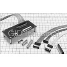
■Extraction Tool
¡Used to release the transmission module from the
Extraction Tool
stationary receptacle.
(2 required)
Fully Connected Condition
The interconnection package consists of 3 main sub-assemblies: Two receptacles and the Transmission Module.
The transmission module, held securely by the guide frame has a mating/un-mating side and a stationary side.
Once the stationary side is inserted in the receptacle, it can not be removed without the use of extraction tool.
The mating/un-mating side allows repeated re-insertion of the receptacle on this side only.
Receptacles
Mating/
un-
mating
side
Transmission
module
assembly
Stationary
side
A302
Jun.1.2018 Copyright 2018 HIROSE ELECTRIC CO., LTD. All Rights Reserved.
IT1 Series●High Speed, Matched-Impedance, Parallel Board-to-board Connector System
2. Recommended Design Guidelines
2-1 Solder Land Pattern
When placing the receptacles on the Printed Circuit Boards using automatic mounting equipment or manually, assure that the
correct diameters of the holes (Fig. 1) are through the entire thickness of the board.
SLocating post hole diameterS
The contacts of receptacle assembly are exposed on the bottom surfaces. The exposed areas of the contacts are a distance
of 0.25 mm minimum from the surface of the Printed Circuit Board, on which the receptacle assembly is placed (Fig.2).
Consideration should be taken not to place or assure insulation of conductive traces under the receptacle assemblies.
Refer to the separate drawings for recommended solder land pattern dimensions of the receptacle, and signals and ground
connection diagram of the transmission module.
(mm)
Automatic placement / (Locating post hole diameter) C dimension: 1.7 mm
Manual placement / (Locating post hole diameter) C dimension: 1.6 mm
+
/ A position accuracy of 0.03 should be exercised from the
-
center of the hole to contact Number 84.
Fig. 1 IT1-168S-SV Recommended Solder Land Pattern
Contact_A Contact_B
Fig. 2 Cross section of IT1 receptacle
2-2 Board-to-Board Spacer heights
The two parallel boards connected by the IT1 connectors should be fastened to additional spacers between them.
Fig. 3 indicates the connector height tolerance and the spacer’s height.
When designing the spacer’s height, consideration should be given to the solder paste thickness and any other features,
which may affect the full mating of the connector.
Fig. 3 indicates design dimensions for the 19 mm board-to-board distance.
(mm)
Fig. 3
A303
Jun.1.2018 Copyright 2018 HIROSE ELECTRIC CO., LTD. All Rights Reserved.
IT1 Series●High Speed, Matched-Impedance, Parallel Board-to-board Connector System
3. Connector Placement
3-1 Packaging Types
¡Two types of packaging are available: semi-hard tray and hard tray. Customers may specify a packaging type suitable for
their automatic placement machines.
* Refer to the separate drawings for the detailed dimensions of the trays.
¡Semi-hard tray packaging ¡Hard tray packaging
168 contacts receptacle: 40 pieces per tray 168 contacts receptacle: 24 pieces per tray
252 contacts receptacle: 30 pieces per tray 252 contacts receptacle: 16 pieces per tray
(mm)
3-2 Automatic placement - Vacuum Pick-and-Place Areas
¡Specify "Vacuum Pick-up Tape Specification".
¡The area and position of the pick-and-place surface are indicated in the diagrams below.
(mm)
A304
Jun.1.2018 Copyright 2018 HIROSE ELECTRIC CO., LTD. All Rights Reserved.
IT1 Series●High Speed, Matched-Impedance, Parallel Board-to-board Connector System
3-3 Receptacle Board Placement
¡When using automatic placement equipment, verify the packaging type and the Pick-and-place areas.
¡When placing manually, pay attention to the possibility of positional shift. Ref. Fig. 4.
* When placing multiple connectors, to assure positional accuracy, it is advised to use automatic placement equipment.
SPrecautions for Manual PlacementS
The orientation posts serve as a prevention measure to avoid incorrect placement of the receptacle assemblies on the board.
The contact terminals must be placed correctly over the corresponding solder pad as shown on Fig. 4-1.
Fig. 4-2 = Incorrect Fig. 4-3 = Incorrect
Fig. 4-1 = Correct
3-4 Recommended Reflow Conditions
A305
Jun.1.2018 Copyright 2018 HIROSE ELECTRIC CO., LTD. All Rights Reserved.
IT1 Series●High Speed, Matched-Impedance, Parallel Board-to-board Connector System
3-5 Solder Repairs
Assure that flux is not reaching the contact areas of the connector.
Wash the assembly as recommended below.
SCleaning ConditionsS
Frequently asked questions
How does Electronics Finder differ from its competitors?

Is there a warranty for the IT1-PICKER(1)?
Which carrier will Electronics Finder use to ship my parts?
Can I buy parts from Electronics Finder if I am outside the USA?
Which payment methods does Electronics Finder accept?
Why buy from GID?

Quality
We are industry veterans who take pride in our work

Protection
Avoid the dangers of risky trading in the gray market

Access
Our network of suppliers is ready and at your disposal

Savings
Maintain legacy systems to prevent costly downtime

Speed
Time is of the essence, and we are respectful of yours
Related Products
Applicator Crimping Tool
Applicator Crimping Tool
Applicator Crimping Tool
Applicator Tool
Applicator Tool
Applicator Tool
Request a Quote

The quote request has been received
Close

Facing challenges or have inquiries? Feel free to contact us!
Call Us +1-469-283-2440
What they say about us
FANTASTIC RESOURCE
One of our top priorities is maintaining our business with precision, and we are constantly looking for affiliates that can help us achieve our goal. With the aid of GID Industrial, our obsolete product management has never been more efficient. They have been a great resource to our company, and have quickly become a go-to supplier on our list!
Bucher Emhart Glass
EXCELLENT SERVICE
With our strict fundamentals and high expectations, we were surprised when we came across GID Industrial and their competitive pricing. When we approached them with our issue, they were incredibly confident in being able to provide us with a seamless solution at the best price for us. GID Industrial quickly understood our needs and provided us with excellent service, as well as fully tested product to ensure what we received would be the right fit for our company.
Fuji
HARD TO FIND A BETTER PROVIDER
Our company provides services to aid in the manufacture of technological products, such as semiconductors and flat panel displays, and often searching for distributors of obsolete product we require can waste time and money. Finding GID Industrial proved to be a great asset to our company, with cost effective solutions and superior knowledge on all of their materials, it’d be hard to find a better provider of obsolete or hard to find products.
Applied Materials
CONSISTENTLY DELIVERS QUALITY SOLUTIONS
Over the years, the equipment used in our company becomes discontinued, but they’re still of great use to us and our customers. Once these products are no longer available through the manufacturer, finding a reliable, quick supplier is a necessity, and luckily for us, GID Industrial has provided the most trustworthy, quality solutions to our obsolete component needs.
Nidec Vamco
TERRIFIC RESOURCE
This company has been a terrific help to us (I work for Trican Well Service) in sourcing the Micron Ram Memory we needed for our Siemens computers. Great service! And great pricing! I know when the product is shipping and when it will arrive, all the way through the ordering process.
Trican Well Service
GO TO SOURCE
When I can't find an obsolete part, I first call GID and they'll come up with my parts every time. Great customer service and follow up as well. Scott emails me from time to time to touch base and see if we're having trouble finding something.....which is often with our 25 yr old equipment.
ConAgra Foods