

 Manufacturers
HIROSE ELECTRIC USA, INC. TM21AR-5B-3232D(50)

Description
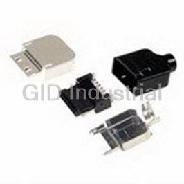
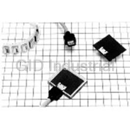
Conn RJ-45 F 32 POS 2.54mm Solder RA Thru-Hole
Part Number
TM21AR-5B-3232D(50)
Price
Request Quote
Manufacturer
HIROSE ELECTRIC USA, INC.
Lead Time
Request Quote
Category
Connectors » Connector Telephone and Telecom
Specifications
Manufacturer
Hirose Electric USA, Inc.
Manufacturers Part #
TM21AR-5B-3232D(50)
Industry Aliases
TM21AR-5B-3232D(50)
Sub-Category
Telephone and Telecom Connectors
Brand
HIROSE
Factory Pack Quantity
1
Datasheet

Extracted Text
Modular Jack Connectors for High-Speed LAN Transmission TM21R Series Built-in Optical Indicators LED Optical indicator Optical pipe ■Features Housing Optical indicator area 1. Supports High-Speed LAN Transmission Meets requirements of TIA/EIA-568-B data wiring standard. Single port configuration meeting CAT5e and multiple port configuration meeting CAT5 transmission performance. Space As such, these products fully support Gigabit Ethernet saving (1000BASE-T) and Fast Ethernet (100BASE-TX) high- speed LAN transmission. Optical indicator 2. Built-in Optical Indicators Optical indicators are integral part of the connectors saving space on customer’s board. Compared with LED type indicators, they do not emit any One additional TM21 multi-port jack can be mounted electrical noise. in the space previously occupied by LEDs. 3. EMI protection Metal shield covers the outer surfaces of the connectors assuring complete protection against electromagnetic interference. Built-in multiple shield and ground contacts assure reliable connection with the mounting panel as well as with the mating connector. 4. FCC Standards Meets requirements of FCC Title 47, Part 68, Subpart F. Built-in LED type Built-in Optical pipe ■Applications (Possibility of type electromagnetic noise (No electromagnetic Telecom Hubs, Routers, Bridges and ATM Transmission emission and noise emission.) Equipment, Ethernet Switches and Networking Equipment, Test and Measurement Equipment, Medical Diagnostic interference.) Equipment. 2012.6 1 Jun.1.2018 Copyright 2018 HIROSE ELECTRIC CO., LTD. All Rights Reserved. TM21R Series●Modular Jack Connectors for High-Speed LAN Transmission ■Product Specifications Current rating 1A Ratings Operating temperature range-25ç to +80ç (Note) Voltage rating 125 V AC Item Specification Conditions 01.Insulation resistance 100 M ohms min 100 V DC 02.Dielectric Withstanding Voltage No flashover or insulation breakdown 500 V AC / one minute (between adjacent contacts) 03.Withstanding voltage No flashover or insulation breakdown 1500 V AC / one minute (between contact and shield) 04.Contact resistance 230 m ohms max. 100mA DC No electrical discontinuity of 5 ms or more Frequency: 10 to 55 Hz, single amplitude of 0.75 mm, 05.Vibration Contact resistance: 250m ohms max. 2 hours / 3 axis 2 No electrical discontinuity of 5ms or more Acceleration of 490 m/s , 11 ms duration, sine half-wave 06.Shock waveform, 3 cycles in each of the 3 axis Contact resistance: 250m ohms max. 07.Durability Contact resistance: 250m ohms max. 200 cycles (mating/unmating) (Temperature: -55ç +5ç to +35ç +85ç +5ç to +35ç / / / Contact resistance: 250 m ohms max. 08.Temperature cycle Duration: 30 5 30 5 (Minutes) / / / Insulation resistance: 100 M ohms min. 5 cycles Contact resistance: 250 m ohms max. 09.Humidity Insulation resistance: 1 M ohms min. (High humidity) 500 hours at temperature of 40ç and humidity of 90% to 95% Insulation resistance: 10 M ohms min. (Dry state) 10.Salt Spray Exposed to density 5% salt water for 48 hours Contact resistance: 250 m ohms max. Note :Includes temperature rise caused by current flow. ■Materials Part Material Finish Remarks Insulator PBT Color: Black UL94V-0 Contact area: Gold plating Contact Copper alloy ------- Termination area: Gold plating flash Optical pipe Poly carbonate Color: Clear ------- Copper alloy Shield Tin plating ------- q Series Name TM21 ■Ordering information w Connector type R : Jack ●Jacks e Jack type number 5 : PCB Right-angle through hole type r Jack performance level code A : CAT5 (Single row, multi-port) ( ) TM21 R - 5 A - 32 32 D - LP 50 B : CAT5 (Double row, multi port) C : Supports CAT5e (Single port) 1 2 3 4 5 6 7 89 t Jack opening code 8 : 8 contacts 32 : 8 contacts /4 ports 48 : 8 contact/6 ports y Number of inserted contacts 8 : 8 contact 32 : 8 contact inserted in 4 ports=32 contacts 48 : 8 contact inserted in 6 ports=48 contacts u Number of rows Blank: Single row D: Double row i Optical pipe LP: With optical pipe inserted Blank: Without optical pipe ( ) o RoHS compliant 50 2 Jun.1.2018 Copyright 2018 HIROSE ELECTRIC CO., LTD. All Rights Reserved. TM21R Series●Modular Jack Connectors for High-Speed LAN Transmission ■Modular Jack Connectors Supporting CAT5e Single Port With Built-in Optical Pipe ● 21 16 (5.5) Contact No.8 Contact No.1 (2.8) 0.35 1 0.45 0.25 11.43 3.05 6.35 2.54 15.75 10.25 13.05 0.8 0.8 24 Contact No.7 Contact No.1 Contact No.8 Contact No.2 11.9 Part Number CL No. RoHS TM21R-5C-88-LP(50) 222-2892-0-50 YES Single Port Without Optical Pipe ● 21 16 (5.5) Contact No.8 Contact No.1 (2.8) 0.35 1 0.45 0.25 11.43 3.05 6.35 2.54 15.75 10.25 13.05 0.8 0.8 24 Contact No.7 Contact No.1 Contact No.8 Contact No.2 11.9 Part Number CL No. RoHS TM21R-5C-88(50) 222-2893-2-50 YES 3 Jun.1.2018 Copyright 2018 HIROSE ELECTRIC CO., LTD. All Rights Reserved. (5.5) (5.5) 3 3 (5.5) (5.5) 3.6 13.75 3.6 13.75 0.8 13.4 0.8 0.8 13.4 0.8 1.7 1.7 TM21R-5C 1 PC TM21R-5C 1 PC 8-Ø1 2-Ø3.2 8-Ø1 TM21R Series●Modular Jack Connectors for High-Speed LAN Transmission BRecommended PCB mounting patterns With Built-in Optical Pipe Without Optical Pipe ● ● 11.9 8.89 6.35 8.89 LED location area 3.81 6.35 LED light emission area 1.27 3.81 1.27 No ground traces 3 1 Contact No. 1 No ground traces 3 Contact No. 8 5 3 2 8 5 3 2 7 6 4 1 7 6 4 1 Printed board edge Printed board edge 11.43MIN 11.43MIN 11.43 Connector front edge 11.43 Connector front edge 15.75 2 15.75 2 No conductive traces No conductive traces *Recommendations for PCB Design 1 PCB mounting pattern 1 The contact arrangement differs between the contact area side and Printed board side. Other Series TM21R Series (1,2,3,4,5,6,7,8 on the contact are side 2,1,3,4,5,6,8,7 on the printed board side) / 7 5 3 1 8 5 3 2 2 Areas indicated should be free of conductive traces. 3 Area indicated should be free of ground traces. 8 6 4 2 7 6 4 1 4 Recommended board thickness: 1.6mm. 5 To assure that the indicator light pipes operates correctly the LED's must be installed directly on the PCB, within recommended dimensions and with light 5 Suggested LEDs emitting center in upward direction. LED light emitting center Contact applicable manufacturer for LED specification. 2.7MAX 1.5MAX BPanel Cutout For Both Types, With and Without Built-in Optical Pipe ● +1 1 (33) 4.5 -2 Lock lever 4.5MIN TM21P--88P TM21R--5C--88--LP PCB mounting surface 1 Connector front surface Panel side 6.75 0 16.4 1 2.8 -0.8 10.25 *Recommendations for Panel Design 1 The shield contacts should connect with the panel cut-out on all sides. Note: IPA cleaning at room temperature is recommended for the cleaning of this product. When an aqueous cleaning agent is to be used, there is a concern that the light pipe (made of polycarbonate resin) may change color; therefore, please make a selection based on a table showing the effects on the resin. These tables are issued by the various manufacturers of cleaning agents. 4 2-Ø3.2 2-Ø1.6 2-Ø1.6 Jun.1.2018 Copyright 2018 HIROSE ELECTRIC CO., LTD. All Rights Reserved. 3.05 13.05 6.35 2.54 0.15 14.1 0.6MIN 6.75 3MIN 6.75 3MIN 3.05 6.35 2.54 6.75 3MIN 6.75 3MIN 3.2MAX TM21R Series●Modular Jack Connectors for High-Speed LAN Transmission ■Modular Receptacles Supporting CAT5 Single row/ multiple ports, with Built-in Optical Pipe ● 59.18 25.9 41.91 13.97 Contact No.8 (6) Contact No.1 0.45 (3.5) Contact No.2 0.25 0.35 Contact No.1 Part Number CL No. RoHS Contact No.7 1.4 53.81 2.5 8.34 Contact No.8 TM21R-5A-3232-LP(50) 222-2873-50 YES 58.93 10.25 15.525 1 1 11.9 BRecommended PCB mounting patterns LED Mount Area Dimensions 58.93 CL-220 Series SML-010 Series 41.91 13.97 11.9 10.9 4-Ø2 8.89 4 LED location area 1.2 1.6 6.35 LED 3.81 light emission area 4 1.27 32-Ø1 1467 2358 SML-020 Series 10.4 2.7 0.6 Printed board edge 1 Contact No. No conductive traces 2 4-Ø2 Connector front edge 53.81 2-Ø3.2 *Recommendations for PCB Design 1 The contact arrangement differs between the contact area side and 4 Suggested LEDs Printed board side. (1,2,3,4,5,6,7,8 on the contact are side / Series Name Manufacturer 2,1,3,4,5,6,8,7 on the printed board side) CL-220 Citizen Electronics Co., Ltd. 2 Areas indicated should be free of conductive traces. SML-010 Rohm Co., LTD 3 Recommended board thickness: 1.6mm. SML-020 Rohm Co., LTD 4 To assure that the indicator light pipes operates correctly the LED’s must be installed directly on the PCB, within recommended dimensions and 1 PCB mounting pattern with light emitting center in upward direction. 2468 1467 Contact applicable manufacturer for LED specification. 1357 2358 5 Jun.1.2018 Copyright 2018 HIROSE ELECTRIC CO., LTD. All Rights Reserved. 6MAX 12.7 8.34 3MIN 5.8 8.34 (6) 2.5 15.525 12.7 1.4 1.3 1 12.7 4.4 5.8 3 1 8.34 3.6 15.4 12.7 (6) 12.7 0.75 15.3 1 1.45 1.5 1.7 15.4 TM21R Series●Modular Jack Connectors for High-Speed LAN Transmission BRecommended Panel Cutout PCB mounting surface 4.5MIN 13.97 1 Shield spring contact 41.91 Panels Side 59.6 +1 (34) 5 1 - 2.5 TM21P-- 88P Connector front surface Lock lever 6 MAX 0 3.5 -1 10.25 *Recommendations for Panel Design 1 The shield contacts should connect with the panel cut-out on all sides. Note: IPA cleaning at room temperature is recommended for the cleaning of this product. When an aqueous cleaning agent is to be used, there is a concern that the light pipe (made of polycarbonate resin) may change color; therefore, please make a selection based on a table showing the effects on the resin. These tables are issued by the various manufacturers of cleaning agents. 6 Jun.1.2018 Copyright 2018 HIROSE ELECTRIC CO., LTD. All Rights Reserved. 0.15 0.4MIN 15.8 TM21R Series●Modular Jack Connectors for High-Speed LAN Transmission Double row / multiple port, with Built-in Optical Pipe ● A 32.5 B Upper row (6) 13.97 Contact No.8 Contact No.1 ( ) TM21R-5B-3232D-LP 50 0.35 0.45 Contact No.1 (3.5) 0.25 Contact No.8 C 1.4 Lower row D 2.5 14.94 Lower row connectors 10.25 22.125 11 contacts 2 3 5 8 1 4 6 7 7 6 4 1 8 5 3 2 Upper row connectors contacts 7.7 ( ) TM21R-5B-4848D-LP 50 11.9 Part Number CL No. A B C D RoHS TM21R-5B-3232D-LP(50) 222-2879-1-50 59.18 41.91 53.81 58.93 YES TM21R-5B-4848D-LP(50) 222-2885-4-50 87.12 69.85 81.75 86.87 BRecommended PCB mounting pattern A B Upper row LED 11.9 4 13.97 mount position 8.89 7.7 Lower row LED 4 6.35 mount position LED light 3.81 emission area 1.27 E- Ø2 1.2 Upper row contact hole Lower row contact hole 8532 7641 D- Ø1 1467 2358 Printed board edge 4- Ø2 1 Contact No. No conductive traces 2 Connector front edge C 2- Ø3.2 Part Number CL No. A B C D E TM21R-5B-3232D-LP(50) 222-2879-1-50 58.93 41.91 53.81 64 4 TM21R-5B-4848D-LP(50) 222-2885-4-50 86.87 69.85 81.75 96 6 1 PCB mounting pattern *Recommendations for PCB Design The contact arrangement differs between the contact area side and 1 Other Series TM21R Series Printed board side. (1,2,3,4,5,6,7,8 on the contact are side / 7531 8532 2,1,3,4,5,6,8,7 on the printed board side) 8642 7641 2 Areas indicated should be free of conductive traces. 3 Recommended board thickness: 1.6mm. 2468 1467 4 To assure that the indicator light pipes operates correctly the LED's 1357 2358 must be installed directly on the PCB, within recommended dimensions 4 Suggested LEDs and with light emitting center in upward direction. Series Name Manufacturer Contact applicable manufacturer for LED specification. CL-220 Citizen Electronics Co., Ltd. 7 Jun.1.2018 Copyright 2018 HIROSE ELECTRIC CO., LTD. All Rights Reserved. 6 MAX 19.3 14.94 1.4 3 MIN 1.3 (6) 1 PBT 2.5 3 (6) 5.8 3.6 28 5.8 8.34 8.34 12.4 12.4 0.75 27.9 1 14.94 14.94 22.125 19.3 1.7 28 TM21R Series●Modular Jack Connectors for High-Speed LAN Transmission Shield spring BPanels Cutout 1 contact spring PCB mounting surface 4.5MIN 13.97 A Panel Side B Part Number CL No. A B RoHS TM21R-5B-3232D-LP(50) 222-2879-1-50 41.91 59.60 YES TM21R-5B-4848D-LP(50) 222-2885-4-50 69.85 87.54 +1 (34) 5 1 -2.5 Lock lever TM21P -- 88P TM21R -- 5B -- * * * * D -- LP 1 Connector front surface 6 MAX 0 1 3.5 -1 10.25 *Recommendations for Panel Design 1 The shield contacts should connect with the panel cut-out on all sides. Note: IPA cleaning at room temperature is recommended for the cleaning of this product. When an aqueous cleaning agent is to be used, there is a concern that the light pipe (made of polycarbonate resin) may change color; therefore, please make a selection based on a table showing the effects on the resin. These tables are issued by the various manufacturers of cleaning agents. 8 Jun.1.2018 Copyright 2018 HIROSE ELECTRIC CO., LTD. All Rights Reserved. 0.15 0.4 MIN 28.4 TM21R Series●Modular Jack Connectors for High-Speed LAN Transmission BTechnical Documentation CAT5e Transmission Characteristics Data Representative values of the various transmission characteristics data for fully mated receptacle (TM21R-5C-88-LP) and plug (TM21P-88P). All plugs in the TM21R-5C Series that were manufactured based on the De-embedded method of the TIA/EIA-568-B.2 standard and meet performance requirements of CAT5e single transmission. Note:These data are for the listed connector combination. Inquire with your Hirose Electric account representative about other combinations. Signal Attenuation ● 0.5 0.4 0.3 0.2 0.1 0 0 10203040 5060708090 100 Frequency(MHz) 1,2 3,6 4,5 7,8 CAT5e Spec Near-End Crosstalk (NEXT) Data ● 120 100 80 60 40 20 0 0 10 203040 50607080 90 100 Frequency(MHz) 1,2-3,6 1,2-4,5 1,2-7,8 3,6-4,5 3,6-7,8 4,5-7,8 CAT5e Spec Return Loss ● 80 60 40 20 0 0 1020304050 60708090 100 Frequency(MHz) 1,2 3,6 4,5 7,8 CAT5e Spec 9 Jun.1.2018 Copyright 2018 HIROSE ELECTRIC CO., LTD. All Rights Reserved. Attenuation(dB) Return Loss(dB) NEXT(dB) TM21R Series●Modular Jack Connectors for High-Speed LAN Transmission Far-End Crosstalk (FEXT) ● 120 100 80 60 40 20 0 0 10 20304050 607080 90 100 Frequency(MHz) 1,2-3,6 1,2-4,5 1,2-7,8 3,6-1,2 3,6-4,5 3,6-7,8 4,5-1,2 4,5-3,6 4,5-7,8 7,8-1,2 7,8-3,6 7,8-4,5 CAT5e Spec Propagation Delay ● 3 2.5 2 1.5 1 0.5 0 0 10203040 5060708090 100 Frequency(MHz) 1,2 3,6 4,5 7,8 CAT5e Spec Propagation Delay (Delay Skew) ● 1.4 1.2 1 0.8 0.6 0.4 0.2 0 0 10203040 5060708090 100 Frequency(MHz) Measurement Value CAT5e Spec 10 Jun.1.2018 Copyright 2018 HIROSE ELECTRIC CO., LTD. All Rights Reserved. FEXT(dB) Delay(ns) Delay Skew(ns) TM21R Series●Modular Jack Connectors for High-Speed LAN Transmission BReference Documentation CAT6 Certification Received ● Only the high quality plugs in the TM21R-5C Series (based on the De-embedded method of the TIA/EIA-568-B.2 standard) clear CAT6 single transmission performance. A certificate was issued by the GHMT, independent European testing company. Certificate of Acceptance Return Loss NEXT 11 Jun.1.2018 Copyright 2018 HIROSE ELECTRIC CO., LTD. All Rights Reserved. TM21R Series●Modular Jack Connectors for High-Speed LAN Transmission GUIDANCE FOR MODULAR CONNECTORS ■Modular Connector Terminal Numbers Unless otherwise specified, see the figures below for the terminal numbers of the product. Plug Jack (mating face) Contact Contact Contact Contact No.8 No.1 No.1 No.8 ■Attention to Plug Mating Use only plugs conforming to FCC standards. FCC PLUG DIMENSIONS Please pay particular attention to dimensions shown right. ■Opening Size and Number of Conductors(6-Conductor) See the figures below for the relationship between the opening size and the number of conductors of the jack connectors. Model 62 Model 66 Model 64 Models 64 and 62 are obtained by removing 1 pin and 2 pins, respectively, from both sides of model 66.For details, please contact us for drawings because only standard models are shown in the catalogs. ■Recommended Soldering for Modular Dip Connectors ●Flow solder (automatic soldering machine) Pre-heat : 90 - 130ç Pre-heat time : 120 seconds maximum Solder temperature : 240 - 260ç Soldering time : 10 seconds maximum ●Hand soldering Soldering iron tip temperature : 350ç Soldering temperature : 5seconds maximum Soldering iron output : 30 - 40W Note: When soldering, use care not to apply excessive force to the connector terminals. ●Recommended Solder composition: Paste, 96.5%Sn/3.0%Ag/0.5%Cu ® 6-3,Nakagawa Chuoh-2-Chome,Tsuzuki-Ku,Yokohama-Shi 224-8540,JAPAN TEL: +81-45-620-3526 Fax: +81-45-591-3726 http://www.hirose.com http://www.hirose-connectors.com The characteristics and the specifications contained herein are for reference purpose. Please refer to the latest customer drawings prior to use. The contents of this catalog are current as of date of 06/2012. Contents are subject to change without notice for the purpose of improvements. 12 Powered by TCPDF (www.tcpdf.org) Jun.1.2018 Copyright 2018 HIROSE ELECTRIC CO., LTD. All Rights Reserved. 5.89 - 6.15
Frequently asked questions
How does Electronics Finder differ from its competitors?

Is there a warranty for the TM21AR-5B-3232D(50)?
Which carrier will Electronics Finder use to ship my parts?
Can I buy parts from Electronics Finder if I am outside the USA?
Which payment methods does Electronics Finder accept?
Why buy from GID?

Quality
We are industry veterans who take pride in our work

Protection
Avoid the dangers of risky trading in the gray market

Access
Our network of suppliers is ready and at your disposal

Savings
Maintain legacy systems to prevent costly downtime

Speed
Time is of the essence, and we are respectful of yours
Related Products
Conn Telephone/Telecom PL 10 POS 0.8mm Solder ST Cable Mount 10 Terminal 1 Port Bag
Conn Telephone/Telecom F 12 POS 1.6mm ST Cable Mount 12 Terminal 1 Port Bag
Conn Telephone/Telecom PL 8 POS 0.8mm Solder ST Cable Mount 8 Terminal 1 Port Tray
Conn Telephone/Telecom RCP 10 POS 0.8mm Solder ST SMD 10 Terminal 1 Port Tray
Conn Telephone/Telecom RCP 10 POS 0.8mm Solder ST SMD 10 Terminal 1 Port
Conn Telephone/Telecom RCP 10 POS 0.8mm Solder ST SMD 10 Terminal 1 Port
Request a Quote

The quote request has been received
Close

Facing challenges or have inquiries? Feel free to contact us!
Call Us +1-469-283-2440
What they say about us
FANTASTIC RESOURCE
One of our top priorities is maintaining our business with precision, and we are constantly looking for affiliates that can help us achieve our goal. With the aid of GID Industrial, our obsolete product management has never been more efficient. They have been a great resource to our company, and have quickly become a go-to supplier on our list!
Bucher Emhart Glass
EXCELLENT SERVICE
With our strict fundamentals and high expectations, we were surprised when we came across GID Industrial and their competitive pricing. When we approached them with our issue, they were incredibly confident in being able to provide us with a seamless solution at the best price for us. GID Industrial quickly understood our needs and provided us with excellent service, as well as fully tested product to ensure what we received would be the right fit for our company.
Fuji
HARD TO FIND A BETTER PROVIDER
Our company provides services to aid in the manufacture of technological products, such as semiconductors and flat panel displays, and often searching for distributors of obsolete product we require can waste time and money. Finding GID Industrial proved to be a great asset to our company, with cost effective solutions and superior knowledge on all of their materials, it’d be hard to find a better provider of obsolete or hard to find products.
Applied Materials
CONSISTENTLY DELIVERS QUALITY SOLUTIONS
Over the years, the equipment used in our company becomes discontinued, but they’re still of great use to us and our customers. Once these products are no longer available through the manufacturer, finding a reliable, quick supplier is a necessity, and luckily for us, GID Industrial has provided the most trustworthy, quality solutions to our obsolete component needs.
Nidec Vamco
TERRIFIC RESOURCE
This company has been a terrific help to us (I work for Trican Well Service) in sourcing the Micron Ram Memory we needed for our Siemens computers. Great service! And great pricing! I know when the product is shipping and when it will arrive, all the way through the ordering process.
Trican Well Service
GO TO SOURCE
When I can't find an obsolete part, I first call GID and they'll come up with my parts every time. Great customer service and follow up as well. Scott emails me from time to time to touch base and see if we're having trouble finding something.....which is often with our 25 yr old equipment.
ConAgra Foods