

 Manufacturers
HONEYWELL 1LS3

Description
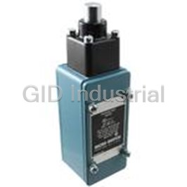
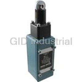
Switch Limit N.O./N.C. SPDT Side Rotary with Adjustable Roller Lever Conduit 0.8A 550VDC Rotary Screw Mount
1LS3
Part Number
1LS3
Price
Request Quote
Manufacturer
HONEYWELL
Lead Time
Request Quote
Category
Switches » Switch Limit
Specifications
Manufacturer
Honeywell
Manufacturers Part #
1LS3
Industry Aliases
1LS3
Sub-Category
Limit Switches
Brand
Micro Switch
Factory Pack Quantity
1
Datasheet

Extracted Text
MICRO SWITCH™ LS General Purpose Limit Switches LS Series Datasheet MICRO SWITCH™ LS General Purpose Limit Switches The Honeywell MICRO SWITCH™ Compact LS Limit Switch Series offers products that have a long record of successful performance in a diverse range of industrial applications. Under severe conditions, its durable and dependable design provides longevity, precision, and consistent repeatability over millions of operations. The compact size and adjustable features propel the LS Series to flourish in a variety of settings under space constraint without sacrificing reliability. Its construction is oil-tight, water-tight and dust tight, and includes die-cast housing, heads and actuators. An assortment of heads and actuators provides a solution for a variety of applications. What makes our switches better? Small size and universal mounting footprint may allow for use in constricted spaces IP67 and NEMA 1, 3, 4, 6 and 13 ratings available provide a dependable solution in most demanding environmental conditions Rugged die-cast metal construction with a wide variety of heads and actuators provides long life across numerous applications MICRO SWITCH™ legacy and expertise - over 55 years of engineering excellence and experience with industrial limit switches Rugged, metal housing packaged for industrial indoor and outdoor applications QUALITY, RELIABLE RUGGED, GLOBAL sensing.honeywell.com 2 ENHANCED PERFORMANCE COMPACT DESIGN F Fe ea at tu ur re es s Along with industry standard mounting dimensions, the LS Series compact design a an nd d Be Ben ne efit fits s allows installation in applications under space constraint while still providing reliable switching performance TWO CIRCUIT DOUBLE BREAK CONTACTS With an AC15, A300 or 10 A electrical rating, the LS Series provides dependable and consistent switching, giving the end users control of two circuits in one switch One switch controls two circuits! ACTUATORS FOR YOUR APPLICATION With many actuators available such as side rotary, plunger, wobble stick and roller plunger, the LS Series is adaptable and has the ability to be applied in a variety of applications SEALED CONSTRUCTION In demanding environmental conditions, IP67 or NEMA 1, 3, 4, 6, and 13 sealing protects against oil, dust and water making the LS Series a dependable solution in a variety of conditions for both indoor and outdoor applications Potential Applications MACHINE TOOL EQUIPMENT Part presence, machine slide/table position, panel and door presence MATERIAL HANDLING Sensing in overhead doors, door interlock, dock locks, conveyance, storage retrieval, carousels, conveyors, and assembly lines VALVE ACTUATION Position sensing of electric valves for waste water treatment plants, power plants, refineries, and pipelines FOOD AND BEVERAGE Sensing during bottling, canning, and packaging SPECIAL MACHINERY Assembly, packaging and testing applications sensing.honeywell.com 3 LS Series MICRO SWITCH™ LS SERIES PRODUCT NOMENCLATURE Switch body SPDT Prod- Modifications Compact Plug- Actuator Switch style uct Actuator description (may be applied to most SPDT in less code family configurations) base standard with 38,1 mm fixed length lever 1 with steel roller low pretravel with 38,1 mm fixed length 19 lever with steel roller low operating torque with 38,1 mm fixed 6 length lever with steel roller side rotary low pretravel, low operating torque with 131 (momentary) 38,1 mm fixed length lever with steel roller CW and CCW standard with adjustable length lever, 1 201 LS 3 actuation. Field 38 mm to 89 mm with nylon roller adjustable for CW (blank) standard with adjustable 127 mm and CCW 10 0.5-14 NPT conduit aluminum rod 2 standard, no lever 9 low pretravel with no lever -L 23 low operating torque with no lever UL/CSA certified with 0.5-14 NPT conduit low pretravel, low operating torque with 56 no lever 202 top pin plunger 1 standard 2 LS -4C n/a top pin plunger 111 plunger boot seal CE with 20 mm conduit 3 203 side roller plunger LS 1 standard 4 204 side pin plunger LS 1 standard -4PG 205 top roller plunger 1 standard 5 LS CE with PG 13,5 mm conduit n/a top roller plunger 8 plunger boot seal standard with 38,1 mm fixed length fork 1 two position side lever with roller 6 206 LS rotary (maintained) 2 no lever side rotary enclo- standard with 38,1 mm fixed length lever 7 n/a LS 1 sure mount with steel roller 208 wobble actuator 1 steel coil spring, 141 mm 208 wobble actuator 3 aluminum rod, 141 mm 8 LS 208 wobble actuator 125 cat whisker, 191 mm stainless steel coil spring, 208 wobble actuator 152 141 mm Not all combinations are available. Please contact your Honeywell provider/representative for assistance. sensing.honeywell.com 4 MICRO SWITCH™ General Purpose Limit Switches Table 1. Specifications Characteristic North America EMEA (Europe) Honeywell general purpose LS-4 limit switch, Honeywell general purpose LS limit switch, Product type compact and plug-in compact and plug-in side rotary, side rotary (maintained) top pin plunger, top roller plunger, wobble coil spring, Acutators wobble aluminum rod, wobble cat whisker, wobble sst coil spring Circuitry single pole double throw (SPDT) double break, single pole double throw (SPDT) double break Electrical 10 A (see Table 2) AC 15, A300; DC 13, P300 compact: epoxy coated zinc die cast Housing material epoxy coated aluminum die cast plug-in: epoxy coated aluminum die cast Conduit 0.5 – 14 NPT 20 mm or PG13,5 Housing seal rating NEMA 1,3,4, 6 and 13 IP67, NEMA 1,4 and 13 standard: -29 °C to 71 °C [-20 °F to 160 °F] standard: -30 °C to 70 °C [-22 °F to 158 °F] Operating temperature high temp.: -29 °C to 120 °C [-20 °F to 248 °F] high temp.: -30 °C to 120 °C [-22 °F to 248 °F] Agency certifications Compact with –L suffix UL file 12252, CSA file 57325 CE, EN60947-5-41, IEC60947-5-4 Table 2. Electrical Ratings Electrical Electrical Ratings Code A 10 A, 120, 240 or 480 Vac; 1/3 hp 120 Vac; 3/4 hp 240 Vac; 0.8 amp, 115 Vdc; 0.4 amp, 230 Vdc; 0.1 amp, 550 Vdc, Pilot Duty, 600 Vac max. B 10 A, 120, 240 or 480 Vac; 1/4 hp 120 Vac; 1/2 hp 240 Vac; Pilot Duty, 600 Vac max. C 10 A, 1/3 hp 120 Vac D 10 A, 120, 240 or 480 Vac; 1/4 hp 120 Vac; 1/2 hp 240 Vac; 0.8 amp, 115 Vdc; 0.4 amp, 230 Vdc; 0.1 amp, 550 Vdc, Pilot Duty, 600 Vac max. E 10 A, 120, 240 or 480 Vac; 1/3 hp 120 Vac; 3/4 hp 240 Vac; Pilot Duty, 600 Vac max. F 5 A, 6 V; 1 A, 24 V; 0.4 A, 220 V G UL & CSA; 10 A, 125, 250 or 480 Vac; 1/3 hp 125 Vac; 3/4 hp 250 Vac; 0.8 amp, 115 Vdc; 0.4 amp, 230 Vdc H UL & CSA; 10 A, 125, 250 or 480 Vac; 1/4 hp 125 Vac; 1/2 hp 250 Vac; 0.8 amp, 115 Vdc; 0.4 amp, 230 Vdc EN60947-5-1, IEC 60947-5-1 Designation & Thermal Current, Rated Operational Rated Operational VA rating Make VA rating Break Category It(Amps) Voltage, Ue Amps, Ie ac AC15, A300 10 120 6 7200 720 J AC15, A300 10 240 3 7200 720 dc DC13, P300 5 125 1.1 138 138 DC13, P300 5 250 0.55 138 138 sensing.honeywell.com 5 LS Series MICRO SWITCH™ LS SERIES ORDER GUIDE/RECOMMENDED LISTINGS (FOR NORTH AMERICA) For listings not shown, contact your Honeywell representative. Table 3. Side Rotary (Momentary), Standard Roller Lever Compact, SPDT Electrical Differen- Plug-in less Operating Torque or Pretravel Overtravel 1 w 0.5-14 NPT Description Rating Bar Chart Operate Point tial Travel Notes base* Force (max.) (min.) conduit (Table 2) (max.) 1LS1 201LS1 side rotary w/ 38,1mm [1.5 in] fixed lever, steel roller A 0,51 Nm [4.5 in-lb] – 20° 30° 12° – 1LS1-L – side rotary w/ 38,1mm [1.5 in] fixed lever, steel roller G 0,51 Nm [4.5 in-lb] – 20° 30° 12° UL & CSA 20° 50° 0° A 0,51 Nm [4.5 in-lb] – 20° 30° 12° – 1LS2 – side rotary, no lever 1-2 1LS2-L – side rotary, no lever G 0,51 Nm [4.5 in-lb] – 20° 30° 12° UL & CSA 3-4 FP OP TT 1LS243 201LS242 side rotary w/ 38,1mm [1.5 in] fixed lever, steel roller A 0,51 Nm [4.5 in-lb] – 20° 30° 12° high-temp. 120 °C [248 °F] DT = 12° 3-4 1LS6 201LS6 side rotary w/ 38,1 mm [1.5 in] fixed lever, steel roller A 0,19 Nm [1.7 in-lb] – 20° 30° 12° low torque 1-2 1LS6-L – side rotary w/ 38,1 mm [1.5 in] fixed lever, steel roller G 0,19 Nm [1.7 in-lb] – 20° 30° 12° low torque, UL & CSA 8° 1LS23 201LS23 side rotary, no lever A 0,19 Nm [1.7 in-lb] 20° 30° 12° low torque 1LS501 201LS501 side rotary w/ 38,1mm [1.5 in] fixed lever, steel roller C 0,51 Nm [4.5 in-lb] – 20° 30° 12° indicator for 120 Vac only 0° 5° 35° 1LS19 201LS19 side rotary w/ 38,1mm [1.5 in] fixed lever, steel roller B 0,51 Nm [4.5 in-lb] – 5° 30° 4° low pretravel 1-2 3-4 1LS9 201SL9 side rotary, no lever B 0,51 Nm [4.5 in-lb] 5° 30° 4° low pretravel OP FP TT DT = 4° 1LS131 – side rotary w/ 38,1 mm [1.5 in] fixed lever, steel roller B 0,19 Nm [1.7 in-lb] 3-4 – 5° 30° 4° low pretravel and low torque 1-2 1LS56 201LS56 side rotary, no lever B 0,19 Nm [1.7 in-lb] 1° 5° 30° 4° low pretravel and low torque 1 Contact closed n; Contact open o. *Requires an 18PA1 Terminal Block (base receptacle) which must be ordered separately. 18PA1 terminal block has 0.5-14 NPT conduit threads. Table 4. Side Rotary (Maintained), Standard Fork Roller Lever Compact, SPDT Electrical Differen- Operating Torque or Operate Pretravel Total travel 1 w 0.5-14 NPT Plug-in less base* Description Rating Bar Chart tial Travel Notes Force Point (max.) (nom.) conduit (Table 2) (max.) side rotary maintained w/ 38,1mm [1.5 in] fork lever, steel rollers, 0° 55° 90° 6LS1 206LS1 A 0,34 Nm [3 in-lb] – 55° 90° 20° opposite side 1-2 3-4 6LS2 206LS2 side rotary maintained, no lever A 0,34 Nm [3 in-lb] – 55° 90° 20° FP OP TT DT = 20° G – 55° 90° 20° 6LS2-L – side rotary maintained, no lever 0,34 Nm [3 in-lb] UL & CSA 3-4 1-2 side rotary maintained w/ 38,1mm [1.5 in] fork lever, nylon rollers, 6LS3 – A 0,34 Nm [3 in-lb] 35° – 55° 90° 20° same side 1 Contact closed n; Contact open o. *Requires an 18PA1 Terminal Block (base receptacle) which must be ordered separately. 18PA1 terminal block has 0.5-14 NPT conduit threads. sensing.honeywell.com 6 MICRO SWITCH™ General Purpose Limit Switches O.T. • Operating torque O.F. • Operating force R.P. • Release point MICRO SWITCH™ LS SERIES ORDER GUIDE/RECOMMENDED LISTINGS (FOR NORTH AMERICA) P.T. • Pretravel For listings not shown, contact your Honeywell representative. O.T. • Overtravel Table 3. Side Rotary (Momentary), Standard Roller Lever D.T. • Differential travel Compact, SPDT Electrical Differen- Plug-in less Operating Torque or Pretravel Overtravel 1 w 0.5-14 NPT Description Rating Bar Chart Operate Point tial Travel Notes base* Force (max.) (min.) conduit (Table 2) (max.) 1LS1 201LS1 side rotary w/ 38,1mm [1.5 in] fixed lever, steel roller A 0,51 Nm [4.5 in-lb] – 20° 30° 12° – 1LS1-L – side rotary w/ 38,1mm [1.5 in] fixed lever, steel roller G 0,51 Nm [4.5 in-lb] – 20° 30° 12° UL & CSA 20° 50° 0° A 0,51 Nm [4.5 in-lb] – 20° 30° 12° – 1LS2 – side rotary, no lever 1-2 1LS2-L – side rotary, no lever G 0,51 Nm [4.5 in-lb] – 20° 30° 12° UL & CSA 3-4 FP OP TT 1LS243 201LS242 side rotary w/ 38,1mm [1.5 in] fixed lever, steel roller A 0,51 Nm [4.5 in-lb] – 20° 30° 12° high-temp. 120 °C [248 °F] DT = 12° 3-4 1LS6 201LS6 side rotary w/ 38,1 mm [1.5 in] fixed lever, steel roller A 0,19 Nm [1.7 in-lb] – 20° 30° 12° low torque 1-2 1LS6-L – side rotary w/ 38,1 mm [1.5 in] fixed lever, steel roller G 0,19 Nm [1.7 in-lb] – 20° 30° 12° low torque, UL & CSA 8° 1LS23 201LS23 side rotary, no lever A 0,19 Nm [1.7 in-lb] 20° 30° 12° low torque 1LS501 201LS501 side rotary w/ 38,1mm [1.5 in] fixed lever, steel roller C 0,51 Nm [4.5 in-lb] – 20° 30° 12° indicator for 120 Vac only 0° 5° 35° 1LS19 201LS19 side rotary w/ 38,1mm [1.5 in] fixed lever, steel roller B 0,51 Nm [4.5 in-lb] – 5° 30° 4° low pretravel 1-2 3-4 1LS9 201SL9 side rotary, no lever B 0,51 Nm [4.5 in-lb] 5° 30° 4° low pretravel OP FP TT DT = 4° 1LS131 – side rotary w/ 38,1 mm [1.5 in] fixed lever, steel roller B 0,19 Nm [1.7 in-lb] 3-4 – 5° 30° 4° low pretravel and low torque 1-2 1LS56 201LS56 side rotary, no lever B 0,19 Nm [1.7 in-lb] 1° 5° 30° 4° low pretravel and low torque 1 Contact closed n; Contact open o. *Requires an 18PA1 Terminal Block (base receptacle) which must be ordered separately. 18PA1 terminal block has 0.5-14 NPT conduit threads. Table 4. Side Rotary (Maintained), Standard Fork Roller Lever Compact, SPDT Electrical Differen- Operating Torque or Operate Pretravel Total travel 1 w 0.5-14 NPT Plug-in less base* Description Rating Bar Chart tial Travel Notes Force Point (max.) (nom.) conduit (Table 2) (max.) side rotary maintained w/ 38,1mm [1.5 in] fork lever, steel rollers, 0° 55° 90° 6LS1 206LS1 A 0,34 Nm [3 in-lb] – 55° 90° 20° opposite side 1-2 3-4 6LS2 206LS2 side rotary maintained, no lever A 0,34 Nm [3 in-lb] – 55° 90° 20° FP OP TT DT = 20° G – 55° 90° 20° 6LS2-L – side rotary maintained, no lever 0,34 Nm [3 in-lb] UL & CSA 3-4 1-2 side rotary maintained w/ 38,1mm [1.5 in] fork lever, nylon rollers, 6LS3 – A 0,34 Nm [3 in-lb] 35° – 55° 90° 20° same side 1 Contact closed n; Contact open o. *Requires an 18PA1 Terminal Block (base receptacle) which must be ordered separately. 18PA1 terminal block has 0.5-14 NPT conduit threads. sensing.honeywell.com 7 LS Series MICRO SWITCH™ LS SERIES ORDER GUIDE/RECOMMENDED LISTINGS (FOR NORTH AMERICA) For listings not shown, contact your Honeywell representative. Table 5. Side Rotary, Adjustable Roller Lever Compact, SPDT Electrical Operating Differen- Pretravel Overtravel 1 w 0.5-14 NPT Plug-in less base* Description Rating Torque or Bar Chart Operate Point tial Travel Notes (max.) (min.) conduit (Table 2) Force (max.) 20° 50° 0° side rotary w/ 38,1 mm to 88,9mm [1.5 in to 3.5 in] 0,51 Nm 1-2 1LS3 201LS3 A – 20° 30° 12° – adjustable lever, nylon roller [4.5 in-lb] 3-4 FP OP TT DT = 12° 3-4 side rotary w/ 38,1 mm to 88,9mm [1.5 in to 3.5 in] 0,51 Nm 1LS3-L – G 1-2 – 20° 30° 12° UL & CSA adjustable lever, nylon roller [4.5 in-lb] 8° 5° 35° 0° side rotary w/ 38,1 mm to 88,9mm [1.5 in to 3.5 in] 0,51 Nm 1LS58 B 1-2 – 5° 30° 4° low pretravel – adjustable lever, nylon roller [4.5 in-lb] 3-4 FP OP TT DT = 4° 3-4 side rotary w/ 38,1 mm to 88,9mm [1.5 in to 3.5 in] 0,19 Nm 1LS59 – B – 5° 30° 4° low pretravel and low torque 1-2 adjustable lever, nylon roller [1.7 in-lb] 1° 1 Contact closed n; Contact open o. *Requires an 18PA1 Terminal Block (base receptacle) which must be ordered separately. 18PA1 terminal block has 0.5-14 NPT conduit threads. Table 6. Side Rotary, Adjustable Rod Lever Compact, SPDT Electrical Operating Differen- Pretravel Overtravel 1 w 0.5-14 NPT Plug-in less base* Description Rating Torque or Bar Chart Operate Point tial Travel Notes (max.) (min.) conduit (Table 2) Force (max.) 0° 20° 50° 0,19 Nm 1-2 1LS10 201LS10 side rotary w/ 140 mm [5.5 in] max. adjustable aluminum rod A – 20° 30° 12° – [1.7 in-lb] 3-4 OP FP TT DT = 12° 3-4 0,19 Nm 1LS10-L – side rotary w/ 140 mm [5.5 in] max. adjustable aluminum rod G 1-2 – 20° 30° 12° UL & CSA [1.7 in-lb] 8° 5° 35° 0° 0,19 Nm 1-2 1LS47 201LS47 side rotary w/ 140 mm [5.5 in] max. adjustable aluminum rod B – 5° 30° 4° low pretravel [1.7 in-lb] 3-4 FP OP TT DT = 4° 3-4 0,11 Nm 1-2 1LS53 201LS51 side rotary w/ 140 mm [5.5 in] max. adjustable aluminum rod B – 5° 30° 4° low pretravel and low torque [1.0 in.lb] 1° 1 Contact closed n; Contact open o. *Requires an 18PA1 Terminal Block (base receptacle) which must be ordered separately. 18PA1 terminal block has 0.5-14 NPT conduit threads. sensing.honeywell.com 8 MICRO SWITCH™ General Purpose Limit Switches O.T. • Operating torque O.F. • Operating force R.P. • Release point P.T. • Pretravel O.T. • Overtravel D.T. • Differential travel Table 5. Side Rotary, Adjustable Roller Lever Compact, SPDT Electrical Operating Differen- Pretravel Overtravel 1 w 0.5-14 NPT Plug-in less base* Description Rating Torque or Bar Chart Operate Point tial Travel Notes (max.) (min.) conduit (Table 2) Force (max.) 20° 50° 0° side rotary w/ 38,1 mm to 88,9mm [1.5 in to 3.5 in] 0,51 Nm 1-2 1LS3 201LS3 A – 20° 30° 12° – adjustable lever, nylon roller [4.5 in-lb] 3-4 FP OP TT DT = 12° 3-4 side rotary w/ 38,1 mm to 88,9mm [1.5 in to 3.5 in] 0,51 Nm 1LS3-L – G 1-2 – 20° 30° 12° UL & CSA adjustable lever, nylon roller [4.5 in-lb] 8° 5° 35° 0° side rotary w/ 38,1 mm to 88,9mm [1.5 in to 3.5 in] 0,51 Nm 1LS58 B 1-2 – 5° 30° 4° low pretravel – adjustable lever, nylon roller [4.5 in-lb] 3-4 FP OP TT DT = 4° 3-4 side rotary w/ 38,1 mm to 88,9mm [1.5 in to 3.5 in] 0,19 Nm 1LS59 – B – 5° 30° 4° low pretravel and low torque 1-2 adjustable lever, nylon roller [1.7 in-lb] 1° 1 Contact closed n; Contact open o. *Requires an 18PA1 Terminal Block (base receptacle) which must be ordered separately. 18PA1 terminal block has 0.5-14 NPT conduit threads. Table 6. Side Rotary, Adjustable Rod Lever Compact, SPDT Electrical Operating Differen- Pretravel Overtravel 1 w 0.5-14 NPT Plug-in less base* Description Rating Torque or Bar Chart Operate Point tial Travel Notes (max.) (min.) conduit (Table 2) Force (max.) 0° 20° 50° 0,19 Nm 1-2 1LS10 201LS10 side rotary w/ 140 mm [5.5 in] max. adjustable aluminum rod A – 20° 30° 12° – [1.7 in-lb] 3-4 OP FP TT DT = 12° 3-4 0,19 Nm 1LS10-L – side rotary w/ 140 mm [5.5 in] max. adjustable aluminum rod G 1-2 – 20° 30° 12° UL & CSA [1.7 in-lb] 8° 5° 35° 0° 0,19 Nm 1-2 1LS47 201LS47 side rotary w/ 140 mm [5.5 in] max. adjustable aluminum rod B – 5° 30° 4° low pretravel [1.7 in-lb] 3-4 FP OP TT DT = 4° 3-4 0,11 Nm 1-2 1LS53 201LS51 side rotary w/ 140 mm [5.5 in] max. adjustable aluminum rod B – 5° 30° 4° low pretravel and low torque [1.0 in.lb] 1° 1 Contact closed n; Contact open o. *Requires an 18PA1 Terminal Block (base receptacle) which must be ordered separately. 18PA1 terminal block has 0.5-14 NPT conduit threads. sensing.honeywell.com 9 LS Series MICRO SWITCH™ LS SERIES ORDER GUIDE/RECOMMENDED LISTINGS (FOR NORTH AMERICA) For listings not shown, contact your Honeywell representative. Table 7. Top Pin Plunger Compact, SPDT Electrical Operating Free Differen- Pretravel Overtravel 1 w 0.5-14 NPT Plug-in less base* Description Rating Torque or Bar Chart Position Operate Point tial Travel Notes (max.) (min.) conduit (Table 2) Force (nom.) (max.) 35,5 33,78 27,43 31,1 N 35,5 mm 33,78 mm ±0,78 mm 1,65 mm 6,35 mm 0,51 mm 1-2 2LS1 202LS1 Top pin plunger (hardened SST) A – [7.0 lb] [1.40 in] [1.33 in ±0.03 in] [0.065 in] [0.25 in] [0.02 in] 3-4 OP FP TT DT = 0,50 3-4 31,1 N 35,5 mm 33,78 mm ±0,78 mm 1,65 mm 6,35 mm 0,51 mm 1-2 2LS1-L – Top pin plunger (hardened SST) G UL & CSA [7.0 lb] [1.40 in] [1.33 in ±0.03 in] [0.065 in] [0.25 in] [0.02 in] 34,29 35,5 33,78 28,23 1-2 3-4 Top pin plunger (hardened SST) 10,0 N 35,5 mm 33,78 mm ±0,78 mm 1,65 mm 5,6 mm 0,23 mm FP OP TT 2LS111 202LS111 E DT = 0,23 lower operating force with boot seal [2.2 lb] [1.40 in] [1.33 in ±0.03 in] [0.065 in] [0.22 in] [0.009 in] 3-4 1-2 28,46 1 Contact closed n; Contact open o. NOTE: Bar chart measurements are in millimeters. *Requires an 18PA1 Terminal Block (base receptacle) which must be ordered separately. 18PA1 terminal block has 0.5-14 NPT conduit threads. Table 8. Top Roller Plunger Compact, SPDT Electrical Operating Differen- Pretravel Overtravel 1 w 0.5-14 NPT Plug-in less base* Description Rating Torque or Bar Chart Operate Point tial Travel Notes (max.) (min.) conduit (Table 2) Force (max.) 31,1 N 45,6 mm 43,95 mm ±0,78 mm 1,65 mm 5,6 mm 0,51 mm 45,6 43,95 38,35 5LS1 205LS1 Top roller plunger (hardened steel roller) A – [7.0 lb] [1.80 in] [1.73 in ±0.03 in] [0.065 in] [0.22 in] [0.02 in] 1-2 3-4 31,1 N 45,6 mm 43,95 mm ±0,78 mm 1,65 mm 5,6 mm 0,51 mm FP OP TT 5LS1-L – Top roller plunger (hardened steel roller) G UL & CSA DT = 0,51 [7.0 lb] [1.80 in] [1.73 in ±0.03 in] [0.065 in] [0.22 in] [0.02 in] 3-4 1-2 Top roller plunger (hardened steel roller) 15,57 N 45,6 mm 43,95 mm ±0,78 mm 1,65 mm 5,6 mm 0,51 mm 5LS8 – lower operating force 44,46 with boot seal [3.5 lb] [1.80 in] [1.73 in ±0.03 in] [0.065 in] [0.22 in] [0.02 in] 1 Contact closed n; Contact open o. NOTE: Bar chart measurements are in millimeters. *Requires an 18PA1 Terminal Block (base receptacle) which must be ordered separately. 18PA1 terminal block has 0.5-14 NPT conduit threads. Table 9. Side Pin Plunger Compact, SPDT Electrical Operating Free Differen- Pretravel Overtravel 1 w 0.5-14 NPT Plug-in less base* Description Rating Torque or Bar Chart Position Operate Point tial Travel Notes (max.) (min.) conduit (Table 2) Force (nom.) (max.) 56,4 54,10 47,75 1-2 3-4 40,0 N 56,4 mm 54,10 mm ±0,78 mm 2,77 mm 6,35 mm 1,02 mm FP OP TT 4LS1 204LS1 Side pin plunger (SST) A – DT = 1,02 [9.0 lb] [2.22 in] [2.13 in ±0.03 in] [0.11 in] [0.25 in] [0.04 in] 3-4 1-2 55,12 1 Contact closed n; Contact open o. NOTE: Bar chart measurements are in millimeters. *Requires an 18PA1 Terminal Block (base receptacle) which must be ordered separately. 18PA1 terminal block has 0.5-14 NPT conduit threads. Table 10. Side Roller Plunger Compact, SPDT Electrical Operating Free Differen- Pretravel Overtravel 1 w 0.5-14 NPT Plug-in less base* Description Rating Torque or Bar Chart Position Operate Point tial Travel Notes (max.) (min.) conduit (Table 2) Force (nom.) (max.) 70,35 67,56 61,21 1-2 Roller plunger may be 3-4 40,0 N 70,35 mm 67,56 mm ±0,78 mm 2,79 mm 6,35 mm 1,02 mm OP FP TT 3LS1 203LS1 Side roller plunger (hardened steel roller) A DT = 1,02 locked in any position [9.0 lb] [2.77 in] [2.66 in ±0.03 in] [0.11 in] [0.25 in] [0.04 in] 3-4 through 360° 1-2 68,58 sensing.honeywell.com 10 MICRO SWITCH™ General Purpose Limit Switches O.T. • Operating torque O.F. • Operating force R.P. • Release point P.T. • Pretravel O.T. • Overtravel D.T. • Differential travel Table 7. Top Pin Plunger Compact, SPDT Electrical Operating Free Differen- Pretravel Overtravel 1 w 0.5-14 NPT Plug-in less base* Description Rating Torque or Bar Chart Position Operate Point tial Travel Notes (max.) (min.) conduit (Table 2) Force (nom.) (max.) 35,5 33,78 27,43 31,1 N 35,5 mm 33,78 mm ±0,78 mm 1,65 mm 6,35 mm 0,51 mm 1-2 2LS1 202LS1 Top pin plunger (hardened SST) A – [7.0 lb] [1.40 in] [1.33 in ±0.03 in] [0.065 in] [0.25 in] [0.02 in] 3-4 OP FP TT DT = 0,50 3-4 31,1 N 35,5 mm 33,78 mm ±0,78 mm 1,65 mm 6,35 mm 0,51 mm 1-2 2LS1-L – Top pin plunger (hardened SST) G UL & CSA [7.0 lb] [1.40 in] [1.33 in ±0.03 in] [0.065 in] [0.25 in] [0.02 in] 34,29 35,5 33,78 28,23 1-2 3-4 Top pin plunger (hardened SST) 10,0 N 35,5 mm 33,78 mm ±0,78 mm 1,65 mm 5,6 mm 0,23 mm FP OP TT 2LS111 202LS111 E DT = 0,23 lower operating force with boot seal [2.2 lb] [1.40 in] [1.33 in ±0.03 in] [0.065 in] [0.22 in] [0.009 in] 3-4 1-2 28,46 1 Contact closed n; Contact open o. NOTE: Bar chart measurements are in millimeters. *Requires an 18PA1 Terminal Block (base receptacle) which must be ordered separately. 18PA1 terminal block has 0.5-14 NPT conduit threads. Table 8. Top Roller Plunger Compact, SPDT Electrical Operating Differen- Pretravel Overtravel 1 w 0.5-14 NPT Plug-in less base* Description Rating Torque or Bar Chart Operate Point tial Travel Notes (max.) (min.) conduit (Table 2) Force (max.) 31,1 N 45,6 mm 43,95 mm ±0,78 mm 1,65 mm 5,6 mm 0,51 mm 45,6 43,95 38,35 5LS1 205LS1 Top roller plunger (hardened steel roller) A – [7.0 lb] [1.80 in] [1.73 in ±0.03 in] [0.065 in] [0.22 in] [0.02 in] 1-2 3-4 31,1 N 45,6 mm 43,95 mm ±0,78 mm 1,65 mm 5,6 mm 0,51 mm FP OP TT 5LS1-L – Top roller plunger (hardened steel roller) G UL & CSA DT = 0,51 [7.0 lb] [1.80 in] [1.73 in ±0.03 in] [0.065 in] [0.22 in] [0.02 in] 3-4 1-2 Top roller plunger (hardened steel roller) 15,57 N 45,6 mm 43,95 mm ±0,78 mm 1,65 mm 5,6 mm 0,51 mm 5LS8 – lower operating force 44,46 with boot seal [3.5 lb] [1.80 in] [1.73 in ±0.03 in] [0.065 in] [0.22 in] [0.02 in] 1 Contact closed n; Contact open o. NOTE: Bar chart measurements are in millimeters. *Requires an 18PA1 Terminal Block (base receptacle) which must be ordered separately. 18PA1 terminal block has 0.5-14 NPT conduit threads. Table 9. Side Pin Plunger Compact, SPDT Electrical Operating Free Differen- Pretravel Overtravel 1 w 0.5-14 NPT Plug-in less base* Description Rating Torque or Bar Chart Position Operate Point tial Travel Notes (max.) (min.) conduit (Table 2) Force (nom.) (max.) 56,4 54,10 47,75 1-2 3-4 40,0 N 56,4 mm 54,10 mm ±0,78 mm 2,77 mm 6,35 mm 1,02 mm FP OP TT 4LS1 204LS1 Side pin plunger (SST) A – DT = 1,02 [9.0 lb] [2.22 in] [2.13 in ±0.03 in] [0.11 in] [0.25 in] [0.04 in] 3-4 1-2 55,12 1 Contact closed n; Contact open o. NOTE: Bar chart measurements are in millimeters. *Requires an 18PA1 Terminal Block (base receptacle) which must be ordered separately. 18PA1 terminal block has 0.5-14 NPT conduit threads. Table 10. Side Roller Plunger Compact, SPDT Electrical Operating Free Differen- Pretravel Overtravel 1 w 0.5-14 NPT Plug-in less base* Description Rating Torque or Bar Chart Position Operate Point tial Travel Notes (max.) (min.) conduit (Table 2) Force (nom.) (max.) 70,35 67,56 61,21 1-2 Roller plunger may be 3-4 40,0 N 70,35 mm 67,56 mm ±0,78 mm 2,79 mm 6,35 mm 1,02 mm OP FP TT 3LS1 203LS1 Side roller plunger (hardened steel roller) A DT = 1,02 locked in any position [9.0 lb] [2.77 in] [2.66 in ±0.03 in] [0.11 in] [0.25 in] [0.04 in] 3-4 through 360° 1-2 68,58 sensing.honeywell.com 11 LS Series MICRO SWITCH™ LS SERIES ORDER GUIDE/RECOMMENDED LISTINGS (FOR NORTH AMERICA) For listings not shown, contact your Honeywell representative. 1 Contact closed n; Contact open o. NOTE: Bar chart measurements are in millimeters. *Requires an 18PA1 Terminal Block (base receptacle) which must be ordered separately. 18PA1 terminal block has 0.5-14 NPT conduit threads. Table 11. Side Rotary with Face Plate Compact, SPDT Electrical Operating Differen- Pretravel Overtravel 1 w 0.5-14 NPT Plug-in less base Description Rating Torque or Bar Chart Operate Point tial Travel Notes (max.) (min.) conduit (Table 2) Force (max.) 20° 50° 0° 1-2 3-4 Face plate with 1LS1 for enclosure installation with 38,1 mm [1.5 in] fixed 0,51 Nm [4.5 OP FP TT 7LS1 – A – 20° 30° 12° – DT = 12° lever, steel roller in-lb] 3-4 1-2 8° 1 Contact closed n; Contact open o. Table 12. Wobble, Coil Spring Compact, SPDT Electrical Operating Differen- Pretravel Overtravel 1 2 w 0.5-14 NPT Plug-in less base* Description Rating Torque or Bar Chart Operate Point (max.) tial Travel Notes (max.) (nom.) conduit (Table 2) Force (max.) Wobble actuated, random motion 141 mm [5.55 in] tin plated, coil spring 1,39 N 59,3 28,6 mm 28,6 mm 30,7 mm 28,6 (nom.) 0 8LS1 208LS1 D – – steel [5.0 oz] [1.125 in] [1.125 in] [1.21 in] 1-2 3-4 Wobble actuated, random motion 141 mm [5.55 in] tin plated, coil spring 1,39 N 28,6 mm 28,6 mm 30,7 mm FP OP TT 8LS1-L – H – UL & CSA steel [5.0 oz] [1.125 in] [1.125 in] [1.21 in] 3-4 1,39 N 28,6 mm 28,6 mm 30,7 mm 1-2 8LS3 208LS3 Wobble actuated, random motion 141 mm [5.55 in] aluminum rod D – – RP [5.0 oz] [1.125 in] [1.125 in] [1.21 in] 127 63,5 (nom.) 0 1-2 3-4 Wobble actuated, random motion 191 mm [7.53 in] stainless steel cat whis- 0,28 N 63,5 mm 63,5 mm 63,5 mm FP OP TT 8LS125 208LS125 D – – ker [1.0 oz] [2.5 in] [2.5 in] [2.5 in] 3-4 1-2 RP 59,3 28,6 (nom.) 0 1-2 3-4 1,39 N 28,6 mm 28,6 mm 30,7 mm FP OP TT 8LS152 208LS152 Wobble actuated, random motion 141 mm [5.55 in] stainless steel coil spring D – – [5.0 oz] [1.125 in] [1.125 in] [1.21 in] 3-4 1-2 RP 1 Contact closed n; Contact open o. NOTE: Bar chart measurements are in millimeters. *Requires an 18PA1 Terminal Block (base receptacle) which must be ordered separately. 18PA1 terminal block has 0.5-14 NPT conduit threads. 2 Operating position in any direction except pull. sensing.honeywell.com 12 MICRO SWITCH™ General Purpose Limit Switches O.T. • Operating torque O.F. • Operating force R.P. • Release point P.T. • Pretravel O.T. • Overtravel 1 D.T. • Differential travel Contact closed n; Contact open o. NOTE: Bar chart measurements are in millimeters. *Requires an 18PA1 Terminal Block (base receptacle) which must be ordered separately. 18PA1 terminal block has 0.5-14 NPT conduit threads. Table 11. Side Rotary with Face Plate Compact, SPDT Electrical Operating Differen- Pretravel Overtravel 1 w 0.5-14 NPT Plug-in less base Description Rating Torque or Bar Chart Operate Point tial Travel Notes (max.) (min.) conduit (Table 2) Force (max.) 20° 50° 0° 1-2 3-4 Face plate with 1LS1 for enclosure installation with 38,1 mm [1.5 in] fixed 0,51 Nm [4.5 OP FP TT 7LS1 – A – 20° 30° 12° – DT = 12° lever, steel roller in-lb] 3-4 1-2 8° 1 Contact closed n; Contact open o. Table 12. Wobble, Coil Spring Compact, SPDT Electrical Operating Differen- Pretravel Overtravel 1 2 w 0.5-14 NPT Plug-in less base* Description Rating Torque or Bar Chart Operate Point (max.) tial Travel Notes (max.) (nom.) conduit (Table 2) Force (max.) Wobble actuated, random motion 141 mm [5.55 in] tin plated, coil spring 1,39 N 59,3 28,6 mm 28,6 mm 30,7 mm 28,6 (nom.) 0 8LS1 208LS1 D – – steel [5.0 oz] [1.125 in] [1.125 in] [1.21 in] 1-2 3-4 Wobble actuated, random motion 141 mm [5.55 in] tin plated, coil spring 1,39 N 28,6 mm 28,6 mm 30,7 mm FP OP TT 8LS1-L – H – UL & CSA steel [5.0 oz] [1.125 in] [1.125 in] [1.21 in] 3-4 1,39 N 28,6 mm 28,6 mm 30,7 mm 1-2 8LS3 208LS3 Wobble actuated, random motion 141 mm [5.55 in] aluminum rod D – – RP [5.0 oz] [1.125 in] [1.125 in] [1.21 in] 127 63,5 (nom.) 0 1-2 3-4 Wobble actuated, random motion 191 mm [7.53 in] stainless steel cat whis- 0,28 N 63,5 mm 63,5 mm 63,5 mm FP OP TT 8LS125 208LS125 D – – ker [1.0 oz] [2.5 in] [2.5 in] [2.5 in] 3-4 1-2 RP 59,3 28,6 (nom.) 0 1-2 3-4 1,39 N 28,6 mm 28,6 mm 30,7 mm FP OP TT 8LS152 208LS152 Wobble actuated, random motion 141 mm [5.55 in] stainless steel coil spring D – – [5.0 oz] [1.125 in] [1.125 in] [1.21 in] 3-4 1-2 RP 1 Contact closed n; Contact open o. NOTE: Bar chart measurements are in millimeters. *Requires an 18PA1 Terminal Block (base receptacle) which must be ordered separately. 18PA1 terminal block has 0.5-14 NPT conduit threads. 2 Operating position in any direction except pull. sensing.honeywell.com 13 LS Series MICRO SWITCH™ LS SERIES ORDER GUIDE/RECOMMENDED LISTINGS (FOR EMEA/EUROPE) For listings not shown, contact your Honeywell representative. Table 13. Side Rotary (Momentary), Standard Roller Lever Compact Compact Electrical Differen- Plug-in less Operating Torque or Pretravel Overtravel 1 20 mm PG 13,5 Description Rating Bar Chart Operate Point tial Travel Notes base* Force (max.) (min.) conduit conduit (Table 2) (max.) 1LS1-4C 1LS1-4PG 201LS1-4 Side rotary, with 38,1 mm [1.5 in] fixed lever, steel roller J 0,51 Nm [4.5 in-lb] 20° 50° – 20° 30° 12° – 0° 1-2 1LS2-4C 1LS2-4PG 201LS2-4 Side rotary, no lever J 0,51 Nm [4.5 in-lb] – 20° 30° 12° – 3-4 FP OP TT 1LS243-4C 1LS243-4PG – Side rotary, with 38,1 mm [1.5 in] fixed lever, steel roller J 0,51 Nm [4.5 in-lb] – 20° 30° 12° High temp. 120 °C [248 °F] DT = 12° 3-4 High temp. 120 °C [248 °F], 1-2 1LS244-4C 1LS244-4PG – Side rotary, with 38,1 mm [1.5 in] fixed lever, steel roller J 0,51 Nm [4.5 in-lb] – 20° 30° 12° 8° fluorcarbon o-rings 0° 5° 35° 1LS19-4C 1LS19-4PG 201LS1-4 Side rotary, with 38,1 mm [1.5 in] fixed lever, steel roller J 0,51 Nm [4.5 in-lb] 1-2 – 5° 30° 4° Low pretravel 3-4 OP FP TT DT = 4° 3-4 1LS56-4C 1LS56-4PG 201LS56-4 Side rotary, lever J 0,19 Nm [1.7 in-lb] 1-2 – 5° 30° 4° Low pretravel & low torque 1° 1 Contact closed n; Contact open o. * Requires an 18PA1-4C Terminal Block (20 mm conduit threads) or 18PA1-4PG Terminal Block (PG13,5 conduit threads) ordered separately. Terminal block is base receptacle. Table 14. Side Rotary (Maintained), Fork Roller Lever Compact Compact Electrical Differen- Plug-in less Operating Torque or Pretravel Total Travel 1 20 mm PG 13,5 Description Rating Bar Chart Operate Point tial Travel Notes base* Force (max.) (nom.) conduit conduit (Table 2) (max.) Side rotary maintained with 38,1 mm fork lever with 0° 20° 50° 6LS1-4C 6LS1-4PG 206LS1-4 J 0,33 Nm [3.01 in-lb] – 55° 90° 20° – 1-2 steel rollers, opp. side 3-4 Side rotary maintained with 38,1 mm fork lever with OP FP TT DT = 12° 6LS3-4C 6LS3-4PG – J 0,33 Nm [3.01 in-lb] – 55° 90° 20° – nylon rollers, same side 3-4 1-2 6LS2-4C 6LS2-4PG – Side rotary maintained, no lever J 0,33 Nm [3.01 in-lb] – 55° 90° 20° – 8° 1 Contact closed n; Contact open o. * Requires an 18PA1-4C Terminal Block (20 mm conduit threads) or 18PA1-4PG Terminal Block (PG13,5 conduit threads) ordered separately. Terminal block is base receptacle. Table 15. Side Rotary, Adjustable Roller Lever Compact Compact Electrical Differen- Plug-in less Operating Torque or Pretravel Overtravel 1 20 mm PG 13,5 Description Rating Bar Chart Operate Point tial Travel Notes base* Force (max.) (min.) conduit conduit (Table 2) (max.) 0° 20° 50° 1-2 3-4 Side rotary, with 25 mm to 89 mm [1.0 in to 3.5 in] adjustable OP FP TT 1LS3-4C 1LS3-4PG 201LS3-4 J 0,51 Nm [4.5 in-lb] DT = 12° – 20° 30° 12° – lever, nylon roller 3-4 1-2 8° 1 Contact closed n; Contact open o. * Requires an 18PA1-4C Terminal Block (20 mm conduit threads) or 18PA1-4PG Terminal Block (PG13,5 conduit threads) ordered separately. Terminal block is base receptacle. sensing.honeywell.com 14 MICRO SWITCH™ General Purpose Limit Switches O.T. • Operating torque O.F. • Operating force R.P. • Release point P.T. • Pretravel O.T. • Overtravel Table 13. Side Rotary (Momentary), Standard Roller Lever D.T. • Differential travel Compact Compact Electrical Differen- Plug-in less Operating Torque or Pretravel Overtravel 1 20 mm PG 13,5 Description Rating Bar Chart Operate Point tial Travel Notes base* Force (max.) (min.) conduit conduit (Table 2) (max.) 1LS1-4C 1LS1-4PG 201LS1-4 Side rotary, with 38,1 mm [1.5 in] fixed lever, steel roller J 0,51 Nm [4.5 in-lb] 20° 50° – 20° 30° 12° – 0° 1-2 1LS2-4C 1LS2-4PG 201LS2-4 Side rotary, no lever J 0,51 Nm [4.5 in-lb] – 20° 30° 12° – 3-4 FP OP TT 1LS243-4C 1LS243-4PG – Side rotary, with 38,1 mm [1.5 in] fixed lever, steel roller J 0,51 Nm [4.5 in-lb] – 20° 30° 12° High temp. 120 °C [248 °F] DT = 12° 3-4 High temp. 120 °C [248 °F], 1-2 1LS244-4C 1LS244-4PG – Side rotary, with 38,1 mm [1.5 in] fixed lever, steel roller J 0,51 Nm [4.5 in-lb] – 20° 30° 12° 8° fluorcarbon o-rings 0° 5° 35° 1LS19-4C 1LS19-4PG 201LS1-4 Side rotary, with 38,1 mm [1.5 in] fixed lever, steel roller J 0,51 Nm [4.5 in-lb] 1-2 – 5° 30° 4° Low pretravel 3-4 OP FP TT DT = 4° 3-4 1LS56-4C 1LS56-4PG 201LS56-4 Side rotary, lever J 0,19 Nm [1.7 in-lb] 1-2 – 5° 30° 4° Low pretravel & low torque 1° 1 Contact closed n; Contact open o. * Requires an 18PA1-4C Terminal Block (20 mm conduit threads) or 18PA1-4PG Terminal Block (PG13,5 conduit threads) ordered separately. Terminal block is base receptacle. Table 14. Side Rotary (Maintained), Fork Roller Lever Compact Compact Electrical Differen- Plug-in less Operating Torque or Pretravel Total Travel 1 20 mm PG 13,5 Description Rating Bar Chart Operate Point tial Travel Notes base* Force (max.) (nom.) conduit conduit (Table 2) (max.) Side rotary maintained with 38,1 mm fork lever with 0° 20° 50° 6LS1-4C 6LS1-4PG 206LS1-4 J 0,33 Nm [3.01 in-lb] – 55° 90° 20° – 1-2 steel rollers, opp. side 3-4 Side rotary maintained with 38,1 mm fork lever with OP FP TT DT = 12° 6LS3-4C 6LS3-4PG – J 0,33 Nm [3.01 in-lb] – 55° 90° 20° – nylon rollers, same side 3-4 1-2 6LS2-4C 6LS2-4PG – Side rotary maintained, no lever J 0,33 Nm [3.01 in-lb] – 55° 90° 20° – 8° 1 Contact closed n; Contact open o. * Requires an 18PA1-4C Terminal Block (20 mm conduit threads) or 18PA1-4PG Terminal Block (PG13,5 conduit threads) ordered separately. Terminal block is base receptacle. Table 15. Side Rotary, Adjustable Roller Lever Compact Compact Electrical Differen- Plug-in less Operating Torque or Pretravel Overtravel 1 20 mm PG 13,5 Description Rating Bar Chart Operate Point tial Travel Notes base* Force (max.) (min.) conduit conduit (Table 2) (max.) 0° 20° 50° 1-2 3-4 Side rotary, with 25 mm to 89 mm [1.0 in to 3.5 in] adjustable OP FP TT 1LS3-4C 1LS3-4PG 201LS3-4 J 0,51 Nm [4.5 in-lb] DT = 12° – 20° 30° 12° – lever, nylon roller 3-4 1-2 8° 1 Contact closed n; Contact open o. * Requires an 18PA1-4C Terminal Block (20 mm conduit threads) or 18PA1-4PG Terminal Block (PG13,5 conduit threads) ordered separately. Terminal block is base receptacle. sensing.honeywell.com 15 LS Series MICRO SWITCH™ LS SERIES ORDER GUIDE/RECOMMENDED LISTINGS (FOR EMEA/EUROPE) For listings not shown, contact your Honeywell representative. Table 16. Side Rotary, Adjustable Rod Lever Compact Compact Electrical Differen- Plug-in less Operating Torque or Pretravel Overtravel 1 20 mm PG 13,5 Description Rating Bar Chart Operate Point tial Travel Notes base* Force (max.) (min.) conduit conduit (Table 2) (max.) 20° 50° 0° 1-2 3-4 FP OP TT 1LS10-4C 1LS10-4PG 201LS10-4 Side rotary with 140 mm [5.5 in] max. adjustable aluminum rod J 0,51 N m [4.5 in-lb] – 20° 30° 12° DT = 12° 3-4 1-2 8° 5° 35° 0° 1-2 3-4 FP OP TT 1LS47-4PG – – Side rotary with 140 mm [5.5 in] max. adjustable alumnum rod J 0,51 N m [4.5 in-lb] DT = 4° – 5° 30° 4° Low pretravel 3-4 1-2 1° 1 Contact closed n; Contact open o. * Requires an 18PA1-4C Terminal Block (20 mm conduit threads) or 18PA1-4PG Terminal Block (PG13,5 conduit threads) ordered separately. Terminal block is base receptacle. Table 17. Top Pin Plunger Compact Compact Electrical Operating Free Differen- Plug-in less Pretravel Overtravel 1 20 mm PG 13,5 Description Rating Torque or Bar Chart Position Operate Point tial Travel Notes base* (max.) (min.) conduit conduit (Table 2) Force (nom.) (max.) 31,4 N 35,5 mm 33,8 mm ±0,7 mm 1,70 mm 6,40 mm 0,50 mm 2LS1-4C 2LS1-4PG 202LS1-4 Top pin plunger (SST) J 35,5 33,8 27,43 [7.06 lb] [1.40 in] [1.33 in ±0.03 in] [0.067 in] [0.252 in] [0.02 in] 1-2 3-4 31,4 N 35,5 mm 33,8 mm ±0,7 mm 1,70 mm 6,40 mm 0,50 mm Gold-plated contacts, OP FP TT – 2LS1-4GPG – Top pin plunger (SST) F DT = 0,50 [7.06 lb] [1.40 in] [1.33 in ±0.03 in] [0.067 in] [0.252 in] [0.02 in] low-energy loads 3-4 1-2 31,4 N 34,29 35,5 mm 33,8 mm ±0,7 mm 1,70 mm 6,40 mm 0,50 mm High temperature, 2LS1-4CN151 – – Top pin plunger (SST) J [7.06 lb] [1.40 in] [1.33 in ±0.03 in] [0.067 in] [0.252 in] [0.02 in 150 °C [302 °F] 1 Contact closed n; Contact open o. NOTE: Bar chart measurements are in millimeters. * Requires an 18PA1-4C Terminal Block (20 mm conduit threads) or 18PA1-4PG Terminal Block (PG13,5 conduit threads) ordered separately. Terminal block is base receptacle. Table 18. Top Roller Plunger Compact Compact Electrical Operating Free Differen- Plug-in less Pretravel Overtravel 1 20 mm PG 13,5 Description Rating Torque or Bar Chart Position Operate Point tial Travel Notes base* (max.) (min.) conduit conduit (Table 2) Force (nom.) (max.) 31,4 N 45,7 mm 44,0 mm ±0,7 mm 1,70 mm 5,56 mm 0,50 mm 45,7 44,0 38,35 5LS1-4C 5LS1-4PG 205LS1-4 Top roller plunger (SST) J [7.06 lb] [1.80 in] [1.73 in ±0.03 in] [0.067 in] [0.219 in] [0.02 in] 1-2 3-4 5LS1-G- 31,4 N OP 45,7 mm 44,0 mm ±0,7 mm 1,70 mm 5,56 mm 0,50 mm Gold-plated contacts, FP TT DT = 0,51 – – Top roller plunger (SST) F 4PG [7.06 lb] [1.80 in] [1.73 in ±0.03 in] [0.067 in] [0.219 in] [0.02 in] low-energy loads 3-4 1-2 31,4 N 45,7 mm 44,0 mm ±0,7 mm 1,70 mm 5,56 mm 0,50 mm High temperature, 5LS1-4CN152 – – Top roller plunger (SST) J 44,46 [7.06 lb] [1.80 in] [1.73 in ±0.03 in] [0.067 in] [0.219 in] [0.02 in] 150 °C [302 °F] 1 Contact closed n; Contact open o. NOTE: Bar chart measurements are in millimeters. * Requires an 18PA1-4C Terminal Block (20 mm conduit threads) or 18PA1-4PG Terminal Block (PG13,5 conduit threads) ordered separately. Terminal block is base receptacle. sensing.honeywell.com 16 MICRO SWITCH™ General Purpose Limit Switches O.T. • Operating torque O.F. • Operating force R.P. • Release point P.T. • Pretravel O.T. • Overtravel D.T. • Differential travel Table 16. Side Rotary, Adjustable Rod Lever Compact Compact Electrical Differen- Plug-in less Operating Torque or Pretravel Overtravel 1 20 mm PG 13,5 Description Rating Bar Chart Operate Point tial Travel Notes base* Force (max.) (min.) conduit conduit (Table 2) (max.) 20° 50° 0° 1-2 3-4 FP OP TT 1LS10-4C 1LS10-4PG 201LS10-4 Side rotary with 140 mm [5.5 in] max. adjustable aluminum rod J 0,51 N m [4.5 in-lb] – 20° 30° 12° DT = 12° 3-4 1-2 8° 5° 35° 0° 1-2 3-4 FP OP TT 1LS47-4PG – – Side rotary with 140 mm [5.5 in] max. adjustable alumnum rod J 0,51 N m [4.5 in-lb] DT = 4° – 5° 30° 4° Low pretravel 3-4 1-2 1° 1 Contact closed n; Contact open o. * Requires an 18PA1-4C Terminal Block (20 mm conduit threads) or 18PA1-4PG Terminal Block (PG13,5 conduit threads) ordered separately. Terminal block is base receptacle. Table 17. Top Pin Plunger Compact Compact Electrical Operating Free Differen- Plug-in less Pretravel Overtravel 1 20 mm PG 13,5 Description Rating Torque or Bar Chart Position Operate Point tial Travel Notes base* (max.) (min.) conduit conduit (Table 2) Force (nom.) (max.) 31,4 N 35,5 mm 33,8 mm ±0,7 mm 1,70 mm 6,40 mm 0,50 mm 2LS1-4C 2LS1-4PG 202LS1-4 Top pin plunger (SST) J 35,5 33,8 27,43 [7.06 lb] [1.40 in] [1.33 in ±0.03 in] [0.067 in] [0.252 in] [0.02 in] 1-2 3-4 31,4 N 35,5 mm 33,8 mm ±0,7 mm 1,70 mm 6,40 mm 0,50 mm Gold-plated contacts, OP FP TT – 2LS1-4GPG – Top pin plunger (SST) F DT = 0,50 [7.06 lb] [1.40 in] [1.33 in ±0.03 in] [0.067 in] [0.252 in] [0.02 in] low-energy loads 3-4 1-2 31,4 N 34,29 35,5 mm 33,8 mm ±0,7 mm 1,70 mm 6,40 mm 0,50 mm High temperature, 2LS1-4CN151 – – Top pin plunger (SST) J [7.06 lb] [1.40 in] [1.33 in ±0.03 in] [0.067 in] [0.252 in] [0.02 in 150 °C [302 °F] 1 Contact closed n; Contact open o. NOTE: Bar chart measurements are in millimeters. * Requires an 18PA1-4C Terminal Block (20 mm conduit threads) or 18PA1-4PG Terminal Block (PG13,5 conduit threads) ordered separately. Terminal block is base receptacle. Table 18. Top Roller Plunger Compact Compact Electrical Operating Free Differen- Plug-in less Pretravel Overtravel 1 20 mm PG 13,5 Description Rating Torque or Bar Chart Position Operate Point tial Travel Notes base* (max.) (min.) conduit conduit (Table 2) Force (nom.) (max.) 31,4 N 45,7 mm 44,0 mm ±0,7 mm 1,70 mm 5,56 mm 0,50 mm 45,7 44,0 38,35 5LS1-4C 5LS1-4PG 205LS1-4 Top roller plunger (SST) J [7.06 lb] [1.80 in] [1.73 in ±0.03 in] [0.067 in] [0.219 in] [0.02 in] 1-2 3-4 5LS1-G- 31,4 N OP 45,7 mm 44,0 mm ±0,7 mm 1,70 mm 5,56 mm 0,50 mm Gold-plated contacts, FP TT DT = 0,51 – – Top roller plunger (SST) F 4PG [7.06 lb] [1.80 in] [1.73 in ±0.03 in] [0.067 in] [0.219 in] [0.02 in] low-energy loads 3-4 1-2 31,4 N 45,7 mm 44,0 mm ±0,7 mm 1,70 mm 5,56 mm 0,50 mm High temperature, 5LS1-4CN152 – – Top roller plunger (SST) J 44,46 [7.06 lb] [1.80 in] [1.73 in ±0.03 in] [0.067 in] [0.219 in] [0.02 in] 150 °C [302 °F] 1 Contact closed n; Contact open o. NOTE: Bar chart measurements are in millimeters. * Requires an 18PA1-4C Terminal Block (20 mm conduit threads) or 18PA1-4PG Terminal Block (PG13,5 conduit threads) ordered separately. Terminal block is base receptacle. sensing.honeywell.com 17 LS Series MICRO SWITCH™ LS SERIES ORDER GUIDE/RECOMMENDED LISTINGS (FOR EMEA/EUROPE) For listings not shown, contact your Honeywell representative. Table 19. Side Plunger Compact Compact Electrical Operating Free Differen- Plug-in less Pretravel Overtravel 1 20 mm PG 13,5 Description Rating Torque or Bar Chart Position Operate Point tial Travel Notes base* (max.) (min.) conduit conduit (Table 2) Force (nom.) (max.) 57,27 54,5 48,94 1-2 3-4 40,1 N 54,5 mm ±1,2 mm 2,77 mm 5,56 mm 1,0 mm FP OP TT 4LS1-4C 4LS1-4PG 204LS1-4 Side pin plunger (SST) J 57,27 mm – DT = 1,0 [9.01 lb] [2.15 in ±0.047 in] [0.109 in] [0.219 in] [0.039 in] 3-4 1-2 55,5 70,37 67,6 62,04 1-2 3-4 40,1 N 67,6 mm ±1,2 mm 2,77 mm 5,56 mm 1,0 mm Roller plunger may be locked in a OP FP TT 3LS1-4C 3LS1-4PG 203LS1-4 Side roller plunger (SST) J DT = 1,0 70,37 mm [9.01 lb] [2.66 in ±0.047 in] [0.109 in] [0.219 in] [0.039 in] position through 360° 3-4 1-2 68,6 1 Contact closed n; Contact open o. NOTE: Bar chart measurements are in millimeters. * Requires an 18PA1-4C Terminal Block (20 mm conduit threads) or 18PA1-4PG Terminal Block (PG13,5 conduit threads) ordered separately. Terminal block is base receptacle. Table 20. Wobble, Coil Spring Compact Compact Electrical Differen- Plug-in less Operating Torque or Pretravel Overtravel 1 2 20 mm PG 13,5 Description Rating Bar Chart Operate Point tial Travel Notes base* Force (max.) (min.) conduit conduit (Table 2) (max.) 59,3 0 28,6 (nom.) Wobble, random motion 141 mm [5.55 in] 28,6 mm 28,6 mm 30,7 mm 8LS1-4C 8LS1-4PG 208LS1-4 J 1,39 N [5.0 oz] – – 1-2 stranded steel cable [1.125 in] [1.125 in] [1.21 in] 3-4 OP FP TT 3-4 Wobble actuated, random motion 141 mm [5.55 in] 28,6 mm 28,6 mm 30,7 mm 8LS3-4C 8LS3-4PG 208LS3-4 J 1,39 N [5.0 oz] – – 1-2 aluminum rod [1.125 in] [1.125 in] [1.21 in] RP 127 0 63,5 (nom.) 1-2 Wobble actuated, random motion 191 mm [7.53 in] 63,5 mm 63,5 mm 63,5 mm 3-4 8LS125-4C 8LS125-4PG 208LS125-4 J 0,28 N [1.0 oz] – – OP FP TT stainless steel cat whisker [2.5 in] [2.5 in] [2.5 in] 3-4 1-2 RP 59,3 28,6 (nom.) 0 1-2 3-4 Wobble actuated, random motion 141 mm [5.55 in] 28,6 mm 28,6 mm 30,7 mm FP OP TT 8LS152-4C 8LS152-4PG 208LS152-4 J 1,39 N [5.0 oz] – – stainless steel coil spring [1.125 in] [1.125 in] [1.21 in] 3-4 1-2 RP 1 Contact closed n; Contact open o. NOTE: Bar chart measurements are in millimeters. *Requires an 18PA1 Terminal Block (base receptacle) which must be ordered separately. 18PA1 terminal block has 0.5-14 NPT conduit threads. 2 Operating position in any direction except pull. sensing.honeywell.com 18 MICRO SWITCH™ General Purpose Limit Switches O.T. • Operating torque O.F. • Operating force R.P. • Release point P.T. • Pretravel O.T. • Overtravel Table 19. Side Plunger D.T. • Differential travel Compact Compact Electrical Operating Free Differen- Plug-in less Pretravel Overtravel 1 20 mm PG 13,5 Description Rating Torque or Bar Chart Position Operate Point tial Travel Notes base* (max.) (min.) conduit conduit (Table 2) Force (nom.) (max.) 57,27 54,5 48,94 1-2 3-4 40,1 N 54,5 mm ±1,2 mm 2,77 mm 5,56 mm 1,0 mm FP OP TT 4LS1-4C 4LS1-4PG 204LS1-4 Side pin plunger (SST) J 57,27 mm – DT = 1,0 [9.01 lb] [2.15 in ±0.047 in] [0.109 in] [0.219 in] [0.039 in] 3-4 1-2 55,5 70,37 67,6 62,04 1-2 3-4 40,1 N 67,6 mm ±1,2 mm 2,77 mm 5,56 mm 1,0 mm Roller plunger may be locked in a OP FP TT 3LS1-4C 3LS1-4PG 203LS1-4 Side roller plunger (SST) J DT = 1,0 70,37 mm [9.01 lb] [2.66 in ±0.047 in] [0.109 in] [0.219 in] [0.039 in] position through 360° 3-4 1-2 68,6 1 Contact closed n; Contact open o. NOTE: Bar chart measurements are in millimeters. * Requires an 18PA1-4C Terminal Block (20 mm conduit threads) or 18PA1-4PG Terminal Block (PG13,5 conduit threads) ordered separately. Terminal block is base receptacle. Table 20. Wobble, Coil Spring Compact Compact Electrical Differen- Plug-in less Operating Torque or Pretravel Overtravel 1 2 20 mm PG 13,5 Description Rating Bar Chart Operate Point tial Travel Notes base* Force (max.) (min.) conduit conduit (Table 2) (max.) 59,3 0 28,6 (nom.) Wobble, random motion 141 mm [5.55 in] 28,6 mm 28,6 mm 30,7 mm 8LS1-4C 8LS1-4PG 208LS1-4 J 1,39 N [5.0 oz] – – 1-2 stranded steel cable [1.125 in] [1.125 in] [1.21 in] 3-4 OP FP TT 3-4 Wobble actuated, random motion 141 mm [5.55 in] 28,6 mm 28,6 mm 30,7 mm 8LS3-4C 8LS3-4PG 208LS3-4 J 1,39 N [5.0 oz] – – 1-2 aluminum rod [1.125 in] [1.125 in] [1.21 in] RP 127 0 63,5 (nom.) 1-2 Wobble actuated, random motion 191 mm [7.53 in] 63,5 mm 63,5 mm 63,5 mm 3-4 8LS125-4C 8LS125-4PG 208LS125-4 J 0,28 N [1.0 oz] – – OP FP TT stainless steel cat whisker [2.5 in] [2.5 in] [2.5 in] 3-4 1-2 RP 59,3 28,6 (nom.) 0 1-2 3-4 Wobble actuated, random motion 141 mm [5.55 in] 28,6 mm 28,6 mm 30,7 mm FP OP TT 8LS152-4C 8LS152-4PG 208LS152-4 J 1,39 N [5.0 oz] – – stainless steel coil spring [1.125 in] [1.125 in] [1.21 in] 3-4 1-2 RP 1 Contact closed n; Contact open o. NOTE: Bar chart measurements are in millimeters. *Requires an 18PA1 Terminal Block (base receptacle) which must be ordered separately. 18PA1 terminal block has 0.5-14 NPT conduit threads. 2 Operating position in any direction except pull. sensing.honeywell.com 19 LS Series Table 21. Terminal Block, Base Receptacle Plug-in less Description base* 18PA1 Terminal block (base receptacle) with 0.5-14 NPT conduit thread. For use with 200LS Series 18PA1-4C Terminal block (base receptacle) with 20 mm conduit threads. For use with 200LS-4 Series 18PA1-4PG Terminal block (base receptacle) with PG13,5 conduit threads. For use with 200LS-4 Series Table 22. Replacement Levers for Side Rotary Switches Catalog Listing Catalot Listing Description (North America) (EMEA/Europe) LSZ51D 6PA78-4 Replacement lever for most 1LS switches with fixed length 38,1 mm lever with Ø19 mm steel roller LSZ52C 6PA44-4 Replacement lever for most 1LS switches w adj. length 38 mm to 90 mm lever with Ø19 mm nylon roller LSZ54M 6PA43-4 Replacement aluminum rod lever for most 1LS switches w adj. rod with max. length 140 mm 6PA80 6PA80-4 Replacement fork lever for 6LS switches w steel rollers on opposite side 6PA102 6PA102-4 Replacement fork lever for 6LS switches w nylon rollers on same side 6PA82 Fork lever for 6LS switches w steel rollers on same side LSZ52D Adjustable length lever 38 mm to 90 mm w Ø19 mm steel roller LSZ52J Adjustable length lever 38 mm to 90 mm w Ø25,4 mm nylon roller LSZ52K Adjustable length lever 38 mm to 90 mm w Ø38,1 mm nylon roller LSZ52M Adjustable length lever 38 mm to 90 mm w Ø50,8 mm rubber roller LSZ52Y Adjustable length lever 38 mm to 90 mm w Ø50,8 mm nylon roller 6PA71 Fixed length lever, 38,1 mm length w Ø19 mm nylon roller 6PA121 Fixed length lever, 38,1 mm length w Ø19 mm steel roller LSZ51L Fixed length lever, 38,1 mm length w Ø19 mm ball bearing steel roller 6PA144 Fixed length lever, 38,1 mm length w Ø19 mm ball bearing steel roller 6PA63 Adjustable stainless steel rod lever, 330 mm max. length 6PA69 Adjustable stainless steel spring rod lever, 127 mm to 190 mm 6PA57 Manually operated Ø38,1mm aluminum button on a 68,1 mm metal lever sensing.honeywell.com 20 MICRO SWITCH™ General Purpose Limit Switches Table 24. Replacement Parts (North America Products) Table 23. Replacement Parts (North America Products) Contact Contact Contact Contact Block Block Block Block Catalog Operating Actuator/ Catalog Operating Actuator/ Compact Plug-in Compact Plug-in Listing Head Lever Listing Head Lever 2LS1-L 2MN1-L – 9PA32 Included w 1LS1-L 2MN1-L – 9PA15 LSZ51D operating 2LS1 1LS1 2MN1 2MN6 9PA32 2MN1 2MN6 9PA15 LSZ51D head 201LS1 201LS1 2LS111 1LS2-L 2MN1-L – 9PA16* Note 1 2MN3 2MN7 – – 201LS111 1LS2 2MN1 2MN6 9PA16* Note 1 3LS1 201LS2 2MN11 2MN9 9PA45 203LS1 1LS3-L 2MN1-L – – – 4LS1 Included w 1LS3 2MN11 2MN9 9PA44 2MN1 2MN6 9PA16* LSZ52C 204LS1 operating 201LS3 head 5LS1-L 2MN1-L – 9PA33 1LS6 2MN1 2MN6 – LSZ51D 5LS1 201LS6 2MN1 2MN6 9PA33 205LS1 1LS9 2MN8 2MN13 9PA16* Note 1 6LS1 201LS9 2MN1 2MN6 9PA47* 6PA80 206LS1 1LS10-L 2MN1-L – – LSZ54M 6LS2-L 2MN1-L – 9PA47* Note 3 1LS10 2MN1 2MN6 – LSZ54M 6LS2 201LS10 2MN1 2MN6 9PA47* Note 3 206LS2 1LS19 2MN8 2MN13 9PA15 LSZ51D 6LS3 2MN1 – 9PA47* 6PA102 201LS19 7LS1 2MN1 – 9PA15 LSZ51D 1LS23 2MN1 2MN6 9PA68* Note 2 8LS1-L 2MN11-L – 9PA58 201LS23 8LS1 1LS47 2MN11 2MN9 9PA58 2MN8 2MN13 – LSZ54M 208LS1 201LS47 8LS3 1LS53 Included w 2MN1 2MN6 9PA49 2MN8 2MN13 – LSZ54M 208LS3 201LS51 operating 1LS56 head 8LS125 2MN8 2MN13 9PA74* Note 2 2MN11 2MN9 9PA54 201LS56 208LS125 8LS152 1LS58 2MN8 – 9PA16* LSZ52C 2MN1 2MN6 9PA42 208LS152 1LS59 2MN8 – 9PA74* LSZ52C * Furnished without actuator 3 1LS131 2MN8 – 9PA74* 6PA121 Fork lever actuators recommended for two position side rotary main- tained 1LS501 2MN1 2MN14 9PA15 LSZ51D 201LS501 * Furnished without actuator ¹ Any auxiliary lever listed can be used ² LSZ54M, 6PA63, 6PA71 or 6PA121 levers only recommended for these catalog listings sensing.honeywell.com 21 LS Series Table 25. Replacement Parts (European Products) Contact Block Basic Catalog Catalog Switch Operating Actuator/ Listing Listing (com- Head Lever LS 200 LS pact only) 1LS1-4C 201LS1-4 2MN1-M 9PA15-4 6PA78-4 1LS2-4C 201LS2-4 2MN1-M 9PA16-4 – 1LS3-4C 201LS3-4 2MN1-M 9PA16-4 6PA44-4 1LS10-4C 201LS10-4 2MN1-M 9PA40-4 6PA43-4 1LS19-4C 201LS19-4 – 9PA15-4 6PA78-4 1LS23-4C – 2MN1-M – – 1LS47-4C – – 9PA40-4 6PA43-4 1LS56-4C 201LS56-4 – 9PA74- * 1LS243-4C – – 914PA15 6PA78-4 1LS244-4C – – 914PA15 6PA78-4 2LS1-4C 202LS1-4 2MN1-M 9PA32-4 Included 3LS1-4C 203LS1-4 – 9PA45-4 with operating 4LS1-4C 204LS1-4 – 9PA44-4 head 5LS1-4C 205LS1-4 2MN1-M 9PA33-4 6LS1-4C 206LS1-4 2MN1-M 9PA46-4 6PA80-4 6LS2-4C 206LS2-4 2MN1-M 9PA47-4 – 6LS3-4C – 2MN1-M 9PA47-4 6PA102-4 8LS1-4C 208LS1-4 2MN1-M 9PA58-4 Included 8LS3-4C 208LS3-4 2MN1-M 9PA49-4 with operating 8LS125-4C 208LS125-4 2MN1-M 9PA54-4 head 8LS152-4C 208LS152-4 2MN1-M 9PA42-4 Note: Operating head includes lever where appropriate and internal plunger. * Because of low operating force, 6PA43-4, 6PA71-4, or 6PA78-4 auxil- iary actuators only are recommended for these listings. sensing.honeywell.com 22 MICRO SWITCH™ General Purpose Limit Switches DIMENSIONAL DRAWINGS Figure 4. 2LS1 Dimensions Figure 1. 1LS1 Dimensions 1,65 26,16 [1.03] [0.065] max. 26,16 [1.03] 26,16 [1.03] 13,46[0.53] pretravel 13,21 [0.52] 13,46[0.53] 25,4 Corrosion-resistant [1.00] 33,78 ±0,762 14,68 ±0,762 steel plunger [1.33 ±0.03] 20,57 [0.81] [0.578 ±0.030] operating position 58,67 [2.31] 68,58 [2.70] 58,67 68,58 [2.31] [2.70] Ø 4,88 [0.192] min. 28,7 15,24 mounting hole for 4,83 [1.13] No. 10 screw (4) [0.6] Ø 4,88 [0.192] min. [0.19] 28,7 1/4-20 UNC 1/4-20 UNC 15,24 40,64 [1.6] mounting hole for 15,09 ±0,38 30,23 [1.13] 4,83 mod thread x mod thread x [0.6] 4,83 [0.19] No. 10 screw (4) [0.594 ±0.015] [1.19] 57,15 ±0,762 14,27 [0.562 ] [0.19] 14,27 [0.562 ] 40,64 [1.6] 30,23 [2.25 ±0.030] 40 [1.57] min. depth (4) 4,83 [0.19] min. depth (4) [1.19] 40 [1.57] Figure 2. 1LS3 Dimensions 60,71 ±1,53 Figure 5. 3LS1 Dimensions [2.39 ±0.06] 50,29 ±1,53 54,10 ±0,762 [1.98 ±0.06] [2.13 ±0.03] operating position 2,77 [0.109] 26,16 [1.03] max. pretravel 13,46[0.53] Ø 19,05 x 6,35 wide 26,16 [1.03] [Ø 0.75 x 0.25 wide] nylon roller 25,4 Ø 25,91 13,46 [0.53] [Ø 1.02] [1.00] 17,78 [0.7] 25,4 38,1 to 88,9 [1.00] [1.5 to 3.5] 14,68 ±0,762 adjustable length [0.578 ±0.030] 58,67 [2.31] 68,58 [2.70] 58,67 Captive [2.31] 68,58 cover [2.70] screw (3) Ø 4,88 [0.192] min. 28,7 mounting hole for [1.13] 4,83 No. 10 screw (4) 1/4-20 UNC Ø 4,88 [0.192] min. [0.19] mod thread x 15,09 ±0,38 40,64 [1.6] mounting hole for 28,7 [1.13] 30,23 14,27 [0.562 ] [0.594 ±0.015] 4,83 [0.19] 4,83 46,48 ±0,762 No. 10 screw (4) min. depth (4) [1.19] [0.19] 1/4-20 UNC 15,09 ±0,38 [1.83 ±0.030] 40,64 [1.6] 40 [1.57] mod thread x 4,83 [0.19] 30,23 [0.594 ±0.015] 14,27 [0.562 ] [1.19] Figure 6. 4LS1 Dimensions min. depth (4) 40 [1.57] 40,64 ±0,762 Figure 3. 1LS10 Dimensions [1.60 ±0.03] operating position 43,18 6,35 [1.70] [0.25] 26,16 [1.03] 2,77 [0.109] 3,18 [0.125] 13,46[0.53] max. pretravel aluminum lever Ø 25,91 25,4 141,22 26,16 [1.03] [5.56] max. [Ø 1.02] [1.00] 17,78 (adjustable) 13,46[0.53] [0.7] 25,4 [1.00] 14,68 ±0,762 [0.578 ±0.030] 58,67 68,58 [2.31] [2.70] Captive cover 68,58 58,67 screw (3) [2.70] [2.31] Ø 4,88 [0.192] min. 28,7 .6 mounting hole for [1.13] 1/4-20 UNC 4,83 No. 10 screw (4) mod thread x [0.19] 15,09 ±0,38 40,64 [1.6] 14,27 [0.562 ] 30,23 [0.594 ±0.015] Ø 4,88 [0.192] min. 4,83 [0.19] 46,48 ±0,762 min. depth (4) 28,7 [1.19] mounting hole for 15,24 [1.13] [1.83 ±0.030] 40 [1.57] [0.6] No. 10 screw (4) 4,83 [0.19] 15,09 ±0,38 1/4-20 UNC 40,64 [1.6] 4,83 30,23 [0.594 ±0.015] mod thread x [0.19] [1.19] 53,09 ±0,762 14,27 [0.562 ] [2.09 ±0.030] min. depth (4) 40 [1.57] sensing.honeywell.com 23 LS Series Figure 7. 5LS1 Dimensions Figure 8. 8LS1 Dimensions 1,65 [0.065] Ø 4,8 [0.189] Switch will operate by max. pretravel Ø 16,66 [Ø 0.656] x 26,16 [1.03] stranded steel moving actuator in any 4,78 [0.188] wide 13,21 [0.52] cable actuator direction except pull corrosion-resistant steel roller and plunger 43,94 ±0,762 16,76 [0.66] [1.73 ±0.03] 27,94 operating position [1.10] 140,97 [5.55] 68,58 58,67 [2.70] [2.31] Captive cover screw (3) 58,67 28,7 .6 Ø 4,88 [0.192] min. [2.31] [1.13] 1/4-20 UNC 4,83 mounting hole for mod thread x [0.19] No. 10 screw (4) 40,64 [1.6] 30,23 14,27 [0.562 ] 4,83 [0.19] [1.19] min. depth (4) 40 [1.57] Ø 4,88 [0.192] min. 1/4-20 UNC 15,24 mounting hole for mod thread x 28,7 [0.6] 14,27 [0.562] 4,83 No. 10 screw (4) [1.13] Figure 6. 6LS1 Dimensions [0.19] 15,09 [0.594] min. depth (4) 35,05 51,31 [2.02] 30,23 4,83 [0.19] [1.38] [1.19] 46,23 [1.82] Ø 19,05 x 6,35 wide 40,64 [1.6] 40 [1.57] 13,97 [0.55] [Ø 0.75 x 0.25 wide] hardened steel roller 26,16 [1.03] 13,46 [0.53] Figure 9. 8LS3 Dimensions 38,1 Ø 4,8 [0.189] Switch will operate by Switch will operate by [1.50] R 34,29 deep anodized moving actuator in any moving actuator in any [1.35] aluminum rod dir direction except pull ection except pull pressed in 14,68 ±0,762 coil spring [0.578 ±0.030] 68,58 [2.70] 140,97 [5.55] 58,67 [2.31] Ø 4,88 [0.192] min. 28,7 mounting hole for 15,24 [1.13] 1/4-20 UNC 4,83 No. 10 screw (4) [0.6] mod thread x [0.19] 15,09 ±0,38 40,64 [1.6] 30,23 14,27 [0.562] [0.594 ±0.015] 4,83 [0.19] [1.19] 58,42 [2.30] min. depth (4) 58,67 40 [1.57] [2.31] Figure 7. 7LS1 Dimensions 30,99 Ø 4,88 [0.192] min. 1/4-20 UNC 15,24 [1.22] mounting hole for mod thread x 28,7 4,83 [0.6] No. 10 screw (4) [1.13] 14,27 [0.562] [0.19] 15,09 [0.594] min. depth (4) 35,05 19,05 30,23 4,83 [0.19] [1.38] [0.75] [1.19] 40 [1.57] 40,64 [1.6] 88,9 [3.50] 79,76 102 [3.14] [4.03] 5,08 [Ø 0.20] 1,52 [0.06] hole (4) 6,35 25,4 3,05 31,75 [0.25] [1.0] [0.12] [1.25] 50,8 6,35 [2.00] [0.25] 63,5 [2.50] sensing.honeywell.com 24 MICRO SWITCH™ General Purpose Limit Switches Figure 10. 8LS125 Dimensions Figure 12. 201LS1 Dimensions Switch will operate by 87,25 [3.435] Switch will operate by Ø 1,02 [0.04] moving actuator in any moving actuator in any spring wire 79,38 [3.125] direction except pull direction except pull treated for corrosion resistance 26,16 [1.03] 38,1 191,26 [1.50] [7.53] 25,4 [1.00] 14,68 ±0,762 [0.578 ±0.030] 77,5 67,67 [3.05] [2.664] 58,67 [2.31] 18,8 1/4-20 UNC [0.74] 4,57 mod thread x [0.18] Ø 4,88 [0.192] min. 1/4-20 UNC 37,49 [1.476] 14,27 [0.562 ] 6,35 15,24 mounting hole for mod thread x 28,7 [0.25] min. depth (3) 29,72 4,83 [0.6] No. 10 screw (4) [1.13] 14,27 [0.562] 48,8 [1.92] [1.17] [0.19] 15,09 [0.594] min. depth (4) 12,7 [0.50] 35,05 30,23 4,83 [0.19] 34,29 [1.35] [1.38] [1.19] 91,54 [3.604] 40 [1.57] 40,64 [1.6] Figure 11. 8LS152 Dimensions Figure 13. 201LS3 Dimensions 60,33 [2.375] Ø 6,7 [0.26] Switch will operate by Switch will operate by coiled stainless 49,91 [1.965] moving actuator in any moving actuator in any steel spring dir direction except pull ection except pull actuator Ø 19,05 x 26,16 [1.03] 6,35 wide 140,97 [Ø 0.75 x 13,21 [0.52] 0.25 wide] [5.55] nylon roller 25,4 [1.00] 14,68 ±0,762 [0.578 ±0.030] 67,67 77,47 [2.664] 57,15 [3.05] [2.25] 58,67 [2.31] 15,24 [0.60] 18,8 [0.74] 4,57 1/4-20 UNC 1/4-20 UNC Ø 4,88 [0.192] min. [0.18] mod thread x 15,24 mod thread x 37,49 [1.476] 6,35 mounting hole for 28,7 14,27 [0.562 ] [0.25] 29,72 [0.6] 4,83 No. 10 screw (4) [1.13] 14,27 [0.562] min. depth (3) 48,8 [1.92] [1.17] [0.19] 15,09 [0.594] min. depth (4) 35,05 12,7 [0.50] 30,23 4,83 [0.19] [1.38] [1.19] 34,29 [1.35] 40,64 [1.6] 40 [1.57] sensing.honeywell.com 25 LS Series Figure 14. 201LS10 Dimensions Figure 17. 204LS1 Dimensions 6,35 43,18 [1.7] 40,64 [1.60] [0.25] operating position 3,18 [0.125] aluminum lever 2,77 26,16 [1.03] [0.109] max. 13,21 [0.52] pretravel 141,22 26,16 [1.03] [5.56] max. (adjustable) 25,4 Ø 6,53 [0.26] [1.00] Ø 6,53 [0.26] Mtg Hole 17,8 Mtg Hole (Thru) (2) 25,4 [0.7] (Thru) (2) [1.00] 77,45 [3.05] 67,67 67,67 77,45 57,15 [2.664] [2.664] [3.05] [2.25] 57,15 [2.25] 15,24 [0.60] 18,8 15,24 [0.60] [0.74] 4,57 18,8 1/4-20 UNC [0.18] [0.74] mod thread x 4,57 1/4-20 UNC 37,49 [1.476] 14,27 [0.562] [0.18] mod thread x 6,35 37,49 [1.476] 29,72 min. depth (3) 14,27 [0.562 ] [0.25] 6,35 48,8 [1.92] [1.17] 29,72 [0.25] 48,8 [1.92] min. depth (3) 12,7 [0.50] [1.17] 12,7 [0.50] 34,29 34,29 [1.35] [1.35] 90,93 [3.58] 87,25 [3.435] Figure 18. 205LS1 Dimensions Figure 15. 202LS1 Dimensions 47,37 [1.87] 47,37 [1.87] 1,65 [0.065] 13,21 1,65 Ø 16,66 [Ø 0.656] x max. pretravel [0.52] [0.065] max. 13,08 Ø 9,07 [0.36] 4,78 [0.188] wide [0.52] 26,16 [1.03] pretravel corrosion-resistant Ø 16,76 [0.66] 26,16 [1.03] steel roller and plunger Ø 6,53 [0.26] Corrosion- 43,94 ±0,762 16,76 [0.66] 33,78 ±0,762 27,94 Mtg Hole Ø 6,53 [0.26] resistant [1.73 ±0.03] [1.33 ±0.03] [1.10] (Thru) (2) Mtg Hole steel plunger operating position operating position (Thru) (2) 5,08 5,08 [0.20] 77,45 [0.20] 67,67 67,67 [3.05] [2.664] 77,45 [2.664] [3.05] 57,15 57,15 [2.25] [2.25] 15,24 15,24 [0.60] [0.60] 18,8 18,8 4,57 [0.74] 1/4-20 UNC [0.74] 4,57 1/4-20 UNC [0.18] mod thread x 37,49 [1.476] [0.18] mod thread x 14,27 [0.562] 37,49 [1.476] 6,35 6,35 14,27 [0.562 ] 29,72 min. depth (3) [0.25] 48,8 [1.92] 29,72 [0.25] min. depth (3) [1.17] 48,8 [1.92] 12,7 [0.50] [1.17] 12,7 [0.50] 34,29 34,29 [1.35] [1.35] Figure 19. 206LS1 Dimensions Figure 16. 203LS1 Dimensions 64,39[2.535] 54,10 ±0,762 46,23 [1.82] [2.13 ±0.03] Ø 19,05 x 6,35 wide operating position 47,37 [1.865] [Ø 0.75 x 0.25 wide] 13,97 [0.55] hardened steel roller 2,77 [0.109] 26,16 [1.03] 26,16 [1.03] max. pretravel 13,08 [0.52] 27,94 Ø 6,53 [0.26] 34,29 38,1 Ø 6,53 [0.26] [1.1] Mtg Hole [1.35] [1.50] R Mtg Hole 17,78 (Thru) (2) (Thru) (2) [0.7] 14,68 ±0,762 [0.578 ±0.030] 67,67 5,08 [2.664] [0.20] 77,45 77,45 [3.05] 67,67 [3.05] 57,15 57,15 [2.664] [2.25] [2.25] 15,24 15,24 [0.60] [0.60] 18,8 18,8 [0.74] [0.74] 4,57 1/4-20 UNC 4,57 1/4-20 UNC [0.18] mod thread x [0.18] mod thread x 37,49 [1.476] 37,49 [1.476] 14,27 [0.562] 6,35 6,35 14,27 [0.562] 29,72 29,72 min. depth (3) 48,8 [1.92] [0.25] [0.25] 48,8 [1.92] min. depth (3) [1.17] [1.17] 12,7 [0.50] 12,7 [0.50] 34,29 34,29 [1.35] [1.35] 104,14 [4.10] 92,2 [3.63] sensing.honeywell.com 26 15,24 [0.60] 15,24 [0.60] 15,24 [0.60] 15,24 [0.60] MICRO SWITCH™ General Purpose Limit Switches Figure 20. 208LS1 Dimensions Figure 22. 208LS125 Dimensions Ø 4,8 [0.189] Ø 1,02 [0.04] spring wire stranded steel Switch will operate treated for corrosion Switch will operate by cable actuator by moving actuator resistance moving actuator in any in any direction 47,37 direction except pull 47,37 except pull [1.865] [1.865] 140,97 191,26 [5.55] [7.53] Ø 6,53 [0.26] Ø 6,53 [0.26] Mtg Hole Mtg Hole (Thru) (2) (Thru) (2) 77,45 77,45 67,67 67,67 [3.05] [3.05] 57,15 57,15 [2.664] [2.664] [2.25] [2.25] 18,8 18,8 [0.74] 1/4-20 UNC [0.74] 1/4-20 UNC 4,57 4,57 mod thread x mod thread x [0.18] [0.18] 37,49 [1.476] 37,49 [1.476] 14,27 [0.562] 14,27 [0.562] 6,35 6,35 min. depth (3) min. depth (3) 29,72 29,72 [0.25] [0.25] 48,8 [1.92] 48,8 [1.92] [1.17] [1.17] 12,7 [0.50] 12,7 [0.50] 34,29 34,29 [1.35] [1.35] Figure 21. 208LS3 Dimensions Figure 23. 208LS152 Dimensions Ø 4,8 [0.189] deep Ø 6,7 [0.26] coiled anodized aluminum rod Switch will operate by stainless steel spring Switch will operate by pressed in coil spring moving actuator in any actuator moving actuator in any direction except pull 47,37 direction except pull 47,37 [1.865] [1.865] 140,97 140,97 [5.55] [5.55] Ø 6,53 [0.26] Ø 6,53 [0.26] Mtg Hole Mtg Hole (Thru) (2) (Thru) (2) 77,45 77,45 67,67 [3.05] 67,67 [3.05] 57,15 [2.664] 57,15 [2.664] [2.25] [2.25] 18,8 18,8 [0.74] 1/4-20 UNC 4,57 [0.74] 1/4-20 UNC 4,57 mod thread x [0.18] mod thread x [0.18] 37,49 [1.476] 14,27 [0.562] 37,49 [1.476] 14,27 [0.562] 6,35 6,35 min. depth (3) 29,72 min. depth (3) [0.25] 29,72 48,8 [1.92] [0.25] 48,8 [1.92] [1.17] [1.17] 12,7 [0.50] 12,7 [0.50] 34,29 34,29 [1.35] [1.35] sensing.honeywell.com 27 LS Series Figure 24. 1LS2-4 Dimensions Figure 26. 1LS10-4 Dimensions 58,5 [2.30] 58,5 [2.30] 40,5 [1.59] 40,5 [1.59] 33,0 33,0 13,5 [1.3] [0.53] [1.3] 13,5 [0.53] 26 [1.02] 38 Ø 19,05 x 6,35 wide Ø 19,05 x 6,35 wide 26 [1.02] [Ø 0.75 x 0.25 wide] [1.5] 38 [Ø 0.75 x 0.25 wide] hardened [1.5] 26 hardened steel roller [1.02] steel roller 26 14,7 [0.58] [1.02] 14,7 [0.58] Ø 5,2 [Ø 0.20] (2) Ø 5,2 mounting 58,7 70 [Ø 0.20] (2) holes [2.31] [2.75] mounting 70 holes 58,7 [2.75] [2.31] 5,2 1,3 15,8 [0.20] (2) 21,5 [0.62] [0.05] (2) 5,2 [0.85] 35 [1.38] 1,3 15,8 30,2 [0.20] (2) 21,5 [0.62] [0.05] (2) [1.19] 40 [1.57] [0.85] 35 [1.38] 40 [1.57] 30,2 [1.19] 40 [1.57] 40 [1.57] Figure 25. 1LS3-4 Dimensions 58,5 [2.30] Figure 27. 2LS1-4 Dimensions 26 [1.02] 40,5 [1.59] 16,8 33,0 [0.66] 13,5 1,7 [1.3] [0.53] 9,01 [0.35] [0.067] 26 [1.02] 13,5 [0.53] Ø 19,05 x 6,35 wide 26 [1.02] Corrosion- 38 [Ø 0.75 x 0.25 wide] 33,8 resistant [1.5] 20,6 hardened [1.33 steel plunger [0.81] steel roller 26 [1.02] 14,7 [0.58] Ø 5,2 98,6 [Ø 0.20] (2) [3.88] Ø 5,2 mounting 70 [Ø 0.20] (2) holes 58,7 58,7 [2.75] mounting [2.31] [2.31] 70 holes [2.75] 5,2 1,3 15,8 [0.20] (2) 21,5 [0.62] [0.05] (2) [0.85] 5,2 1,3 15,8 35 [1.38] 21,5 30,2 [0.20] (2) [0.62] [0.05] (2) [1.19] [0.85] 40 [1.57] 35 [1.38] 40 [1.57] 30,2 [1.19] 40 [1.57] 40 [1.57] Figure 28. 4LS1-4 Dimensions 46,5 [1.83] 26 [1.02] 26 [1.02] 13,5 2,77 [0.109] [0.53] max. pretravel Ø 25,91 9 [0.35] [Ø 1.02] 18,3 [0.72] Corrosion- resistant Ø 5,2 96 steel plunger [Ø 0.20] (2) [3.78] mounting holes 58,7 70 [2.31] [2.75] 5,2 1,3 15,8 [0.20] (2) 21,5 [0.05] (2) [0.62] [0.85] 35 [1.38] 30,2 [1.19] 40 [1.57] 40 [1.57] sensing.honeywell.com 28 MICRO SWITCH™ General Purpose Limit Switches Figure 29. 5LS1-4 Dimensions Figure 32. 201LS1-4 Dimensions 26 [1.02] 1,7 [0.07] 58,5 [2.30] pretravel 13,5 26 26 40 [1.57] [0.53] [1.02] 13 [0.51] Ø 16,66 x 5 wide [Ø 0.66 x 0.20 wide] 44 26 steel roller [1.73] [1.02] and plunger 38,1 [1.50] 5,1 Ø 5,2 14,68 ±0,762 [0.20] [0.578 ±0.030] [Ø 0.20] (2) mounting holes 58,7 70 [2.31] 77,3 [2.75] [3.04] 81 57 [2.24] 67,67 91 [3.19] [2.664] [3.58] 15,8 5,2 [0.62] 1,3 [0.20] (2) 15 [0.59] [0.05] (2) 21,5 30,2 [0.85] [1.19] 35 [1.38] 5,54 [0.22] max. (3) 40 [1.57] 37,5 [1.48] 30 for M5 screw 5,1 [0.20] 40 [1.57] [1.18] 49 [1.93] Figure 30. 6LS1-4 Dimensions Figure 33. 206LS1-4 Dimensions 64 [2.52] 46 [1.81] 64,39[2.535] 46,23 [1.82] 14 13,5 13,97 [0.55] [0.53] [0.55] 13 Ø 19,05 x [0.51] 6,35 wide 26 [1.02] [Ø 0.75 x 26 0.25 wide] [1.02] Ø 19,05 x 6,35 wide hardened steel roller (2) [Ø 0.75 x 0.25 wide] hardened 34 34 [1.34] 34 steel roller (2) [1.34] 14,68 ±0,762 [1.34] 5,1 [0.578 ±0.030] [0.20] 5,2 [0.20] 77,3 Ø 5,2 [3.04] 81 [Ø 0.20] (2) 57 [2.24] 67,67 91 [3.19] mounting [2.664] [3.58] 70 58,7 holes [2.75] [2.31] 15 [0.59] 5,54 [0.22] max. (3) 30 37,5 [1.48] for M5 screw [1.18] 5,1 [0.20] 5,2 1,3 15,8 49 [1.93] [0.20] (2) 21,5 [0.62] [0.05] (2) [0.85] 35 [1.38] 30,2 Figure 34. 201LS3-4 Dimensions [1.19] 40 [1.57] 40 [1.57] 58,5 [2.30] Figure 31. 8LS1-4 Dimensions 26 40 [1.57] [1.02] Ø 4,8 [0.189] 13 [0.51] stranded steel Switch will operate by cable actuator moving actuator in any direction except pull 26 38 [1.02] [1.5] 5,1 14,68 140,97 [0.578] [0.20] [5.55] 77,3 [3.04] 57 [2.24] 81 67,67 [3.19] 91 [2.664] [3.58] Ø 5,2 [Ø 0.20] (2) mounting 70 15 [0.59] holes 58,7 [2.75] [2.31] 5,54 30 37,5 [1.48] [0.22] max. (3) 5,1 [0.20] [1.18] for M5 screw 49 [1.93] 5,2 1,3 15,8 [0.20] (2) 21,5 [0.62] [0.05] (2) [0.85] 35 [1.38] 30,2 [1.19] 40 [1.57] 40 [1.57] sensing.honeywell.com 29 LS Series Figure 35. 201LS10-4 Dimensions Figure 38. 205LS1-4 Dimensions 26 [1.02] 58,5 [2.30] 16,8 [0.66] 26 26 40 [1.57] [1.02] 9 [0.35] [1.02] 1,65 13 Corrosion- [0.51] [0.065] max. resistant pretravel steel plunger 26 33,7 [1.33] 20,6 [0.81] 5,1 [0.20] [1.02] 38 [1.5] 34 [1.34] 5,1 14,68 77,3 [0.20] [0.578] [3.04] 67,67 57 [2.24] 81 [2.664] 91 [3.19] [3.58] 77,3 [3.04] 57 [2.24] 67,67 81 91 [3.19] [2.664] [3.58] 15 [0.59] 5,54 37,5 [1.48] 15 [0.59] [0.22] max. (3) 34 5,1 [0.20] for M5 screw [1.34] 49 [1.93] 5,54 30 37,5 [1.48] [0.22] max. (3) 5,1 [0.20] [1.18] Figure 39. 208LS1-4 Dimensions for M5 screw 49 [1.93] 26 [1.02] 26 [1.02] Figure 36. 202LS1-4 Dimensions 5 [0.20] Stainless steel coil 26 spring actuator [1.02] (208LS152-4 only) 16,8 [0.66] 26 141 [1.02] [5.55] 9 [0.35] 1,65 Corrosion- [0.065] max. 5,1 resistant [0.20] pretravel steel plunger 33,7 [1.33] 20,6 [0.81] 5,1 [0.20] 77,3 [3.04] 81 67,67 57 [2.24] 77,3 [3.19] 91 [2.664] [3.04] [3.58] 67,67 57 [2.24] 81 [2.664] 91 [3.19] [3.58] 15 [0.59] 5,54 15 [0.59] 37,5 [1.48] 34 [0.22] max. (3) 5,1 [0.20] [1.34] for M5 screw 49 [1.93] 5,54 37,5 [1.48] [0.22] max. (3) 34 5,1 [0.20] for M5 screw [1.34] 49 [1.93] Figure 37. 204LS1-4 Dimensions 54 [2.13] 46 [1.81] 26 [1.02] 26 [1.02] 13 [0.51] 18,2 [0.72] 26 28 [1.10] [1.02] 9 [0.35] 5,1 77,3 [0.20] [3.04] 67,67 57 [2.24] 91 [2.664] [3.58] 15 [0.59] 5,54 37,5 [1.48] 30 [0.22] max. (3) 5,1 [0.20] [1.18] for M5 screw 49 [1.93] sensing.honeywell.com 30 ADDITIONAL INFORMATION WARNING The following associated literature is available on the Honeywell web PERSONAL INJURY site at sensing.honeywell.com: DO NOT USE these products as safety or emergency stop • Product installation instructions devices or in any other application where failure of the product • Aerospace range guide could result in personal injury. • Transportation range guide Failure to comply with these instructions could result in • Limits and Machine Safety range guide death or serious injury. • Product application-specific information – Application Note: Automated Storage and Retrieval System WARNING – Limit and Enclosed Switches Application Information MISUSE OF DOCUMENTATION – Limit and Enclosed Switches Operating Characteristics • The information presented in this product sheet is for – Limit and Enclosed Switches Reference Standards reference only. Do not use this document as a product – Limit and Enclosed Switches Typical Applications installation guide. • Complete installation, operation, and maintenance information is provided in the instructions supplied with each product. Failure to comply with these instructions could result in death or serious injury. WARRANTY/REMEDY Honeywell warrants goods of its manufacture as being free of defective materials and faulty workmanship. Honeywell’s standard product warranty applies unless agreed to otherwise by Honeywell in writing; please refer to your order acknowledgement or consult your local sales office for specific warranty details. If warranted goods are returned to Honeywell during the period of coverage, Honeywell will repair or replace, at its option, without charge those items it finds defective. The foregoing is buyer’s sole remedy and is in lieu of all other warranties, expressed or implied, including those of merchantability and fitness for a particu- Find out more lar purpose. In no event shall Honeywell be liable for conse- Honeywell serves its customers quential, special, or indirect damages. through a worldwide network of sales offices, representatives While we provide application assistance personally, through our and distributors. For application literature and the Honeywell website, it is up to the customer to assistance, current specifications, determine the suitability of the product in the application. pricing or name of the nearest Authorized Distributor, contact Specifications may change without notice. The information we your local sales office. supply is believed to be accurate and reliable as of this printing. To learn more about Honeywell’s However, we assume no responsibility for its use. sensing and control products, call +1-815-235-6847 or 1-800-537-6945, visit sensing.honeywell.com, or e-mail inquiries to info.sc@honeywell.com Sensing and Control Honeywell 1985 Douglas Drive North 002403-1-EN IL50 GLO Golden Valley, MN 55422 June 2015 honeywell.com Copyright © 2015 Honeywell International Inc. All rights reserved.
Frequently asked questions
How does Electronics Finder differ from its competitors?

Is there a warranty for the 1LS3?
Which carrier will Electronics Finder use to ship my parts?
Can I buy parts from Electronics Finder if I am outside the USA?
Which payment methods does Electronics Finder accept?
Why buy from GID?

Quality
We are industry veterans who take pride in our work

Protection
Avoid the dangers of risky trading in the gray market

Access
Our network of suppliers is ready and at your disposal

Savings
Maintain legacy systems to prevent costly downtime

Speed
Time is of the essence, and we are respectful of yours
Related Products
Switch Limit N.O./N.C. SPDT Side Rotary Conduit 0.5A 250VDC 1/4HP 0.5N Rotary Screw Mount 11CX11B-D0...
Request a Quote

The quote request has been received
Close

Facing challenges or have inquiries? Feel free to contact us!
Call Us +1-469-283-2440
What they say about us
FANTASTIC RESOURCE
One of our top priorities is maintaining our business with precision, and we are constantly looking for affiliates that can help us achieve our goal. With the aid of GID Industrial, our obsolete product management has never been more efficient. They have been a great resource to our company, and have quickly become a go-to supplier on our list!
Bucher Emhart Glass
EXCELLENT SERVICE
With our strict fundamentals and high expectations, we were surprised when we came across GID Industrial and their competitive pricing. When we approached them with our issue, they were incredibly confident in being able to provide us with a seamless solution at the best price for us. GID Industrial quickly understood our needs and provided us with excellent service, as well as fully tested product to ensure what we received would be the right fit for our company.
Fuji
HARD TO FIND A BETTER PROVIDER
Our company provides services to aid in the manufacture of technological products, such as semiconductors and flat panel displays, and often searching for distributors of obsolete product we require can waste time and money. Finding GID Industrial proved to be a great asset to our company, with cost effective solutions and superior knowledge on all of their materials, it’d be hard to find a better provider of obsolete or hard to find products.
Applied Materials
CONSISTENTLY DELIVERS QUALITY SOLUTIONS
Over the years, the equipment used in our company becomes discontinued, but they’re still of great use to us and our customers. Once these products are no longer available through the manufacturer, finding a reliable, quick supplier is a necessity, and luckily for us, GID Industrial has provided the most trustworthy, quality solutions to our obsolete component needs.
Nidec Vamco
TERRIFIC RESOURCE
This company has been a terrific help to us (I work for Trican Well Service) in sourcing the Micron Ram Memory we needed for our Siemens computers. Great service! And great pricing! I know when the product is shipping and when it will arrive, all the way through the ordering process.
Trican Well Service
GO TO SOURCE
When I can't find an obsolete part, I first call GID and they'll come up with my parts every time. Great customer service and follow up as well. Scott emails me from time to time to touch base and see if we're having trouble finding something.....which is often with our 25 yr old equipment.
ConAgra Foods