

 Manufacturers
HONEYWELL 1TB1-3

Description
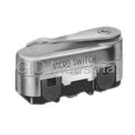
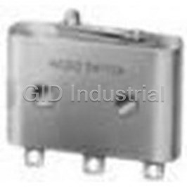
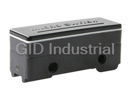
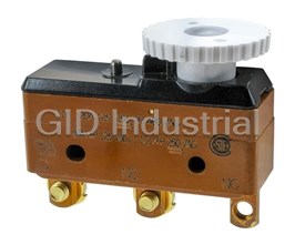
Switch Snap Action Plunger Solder 10A 250VAC 3.61N Screw Mount
1TB1-3
Part Number
1TB1-3
Price
Request Quote
Manufacturer
HONEYWELL
Lead Time
Request Quote
Category
Switches » Switch Snap Action
Specifications
Manufacturer
Honeywell
Manufacturers Part #
1TB1-3
Lead Time
9 Week Lead Time
Industry Aliases
1TB1-3
Sub-Category
Snap Action Switches
Brand
Micro Switch
Factory Pack Quantity
25
Datasheet

Extracted Text
MICRO SWITCH™ Specialty Large Basic Switches 004956 BS | DT | MN | MT | TB Series Issue 3 Datasheet FEATURES • Double pole design in small package allows for control of two independent circuits (DT Series and MN Series) • Switch design with adjustable operating characteristics (BS Series) • Higher dc current capacity at 125 Vdc and 250 Vdc with magnetic blow-out contact design (MT Series) • Compact switch package with double-break contacts (MN Series and TB Series) • Variety of integral plunger and lever options or auxiliary plunger and lever options • Most switches mount on the common 25,4 mm [1.00 in] centers • Metal or plastic enclosures available to prevent contact with DESCRIPTION switch terminals MICRO SWITCH™ premium specialty large snap-action • Select switch series with a temperature range of switches are designed for repeatability and enhanced life. -55 °C to 85 °C [-67 °F to 185 °F] These series of precision switches feature application-specific • Agency certifications with CSA and UL for select catalog characteristics. From double-break circuitry to handling power listings duty electrical loads, MICRO SWITCH™ premium large snap- • MIL-PRF-8805 for select DT Series catalog listings action switches are suitable for a variety of applications. BS Series switches offer alternatives to solve challenging switch POTENTIAL APPLICATIONS applications. These unique solutions can provide adjustable • Temperature and pressure switch assemblies operating characteristics, sequential outputs, or impact • Motor and solenoid dc control circuits actuation (no external plunger). • Welder control circuits DT Series switches consist of two independent single-pole • Switch element in machine tools double throw (SPDT) contacts in one housing controlled by an • Switch element in manually operated devices integral common actuator. The DPDT contact configuration provides a contact for the control circuit and a different contact VALUE TO CUSTOMERS for the signal or auxiliary circuit. • Can control two independent circuits in a small package (DT MT Series magnetic blow-out switches are designed to switch Series and TB Series) high-capacity (125 Vdc/250 Vdc) electrical loads. An integral • Unique switch design with adjustable operating characteristics magnet around the contact gap deflects the arc away from the (BS Series) contacts, extending switch life. Vents between the cover and • Magnetic blow-out contact design permits control of dc housing allow the hot gas to escape. circuits in a small package size (MT Series) Easy to gang mount, MN Series single pole double throw • Double break switch design adds element of redundancy double-break switches are for use with limit or control within small switch package (MN series and TB Series) mechanisms on machine tools, presses, or other equipment. MICRO SWITCH™ TB Series miniature single pole double throw PORTFOLIO double break switches offer a means of controlling circuits The five different series of premium specialty large basic similar to the MN Series switches except in a smaller package. switches (BS Series, DT Series, MN Series, MT Series, and TB Series) complements the four different families of premium large DIFFERENTIATION basic switch series (BA Series, BE Series, BM Series, and BZ • Double pole switch options in small package for increased Series). application flexibility • Double break switch options in compact design requires less space on equipment • -55 °C [-67 °F] low temperature capability for harsh outdoor or cold room applications Sensing and Productivity Solutions MICRO SWITCH™ Specialty Large Basic Switches BS | DT | MN | MT | TB Series Table 1. Specifications Series BS Series DT Series MT Series MN Series TB Series same size as the adjustable switch MICRO SWITCH™ designed for power smaller double-break Differentiator characteristics or BZ Series, but double double-break contacts duty dc loads package special circuitry pole double throw (DPDT) control circuits to pressure or design permits switch high capacity limit or control limit or control Use temperature switch several different wiring (125 Vdc and 250 Vdc) mechanisms mechanisms assemblies configurations systems Ampere Up to 20 A 10 A 10 A 15 A 10 A rating Circuitry SPDT, SPNC DPDT SPDT SPDT DB SPDT-DB, DPDT-DB 3,34 N to 5,56 N Operating 3,34 N to 5,00 N 1,95 N to 3,1 N 1,95 N to 3,89 N Up to 9,73 N [35 oz] [12.0 oz to 20.0 oz] force [12 oz to 18 oz] max. [7 oz to 11 oz] [7 oz to 14 oz] max. max. Termination solder, screw screw solder, screw screw solder, screw impact actuation (no pin plunger, straight pin plunger, straight plunger), pin plunger plunger, straight lever, lever, roller lever, Actuator pin plunger pin plunger (SST), overtravel reversed lever, roller flexible leaf, flexible plunger (SST) lever leaf with roller 125 Vac, 250 Vac, Voltage up to 480 Vac 125 Vdc, 250 Vdc 480 Vac 250 Vac 28 Vdc UL recognized; Agency UL, CSA (most UL recognized; UL recognized, CSA certified, UL recognized approvals models) CSA certified CSA certified MIL-PRF-8805 Operating -55 °C to 85 °C -55 °C to 85 °C -55 °C to 82 °C -55 °C to 85 °C -55 °C to 125 °C temperature [-67 °F to 185 °F] [-67 °F to 185 °F] [-67 °F to 180 °F] [-67 °F to 185 °F] [-67 °F to 257 °F] Contact silver silver silver silver silver material general purpose general purpose general purpose Housing phenolic arc resistant melamine phenolic phenolic phenolic Expected Up to 20,000,000 mechanical operations at 95 % 3,000,000 operations 100,000 operations 10,000,000 cycles 7,000,000 operations life survival 2 sensing.honeywell.com MICRO SWITCH™ Specialty Large Basic Switches BS | DT | MN | MT | TB Series O.F. • Operating force R.F. • Release force P.T. • Pretravel O.T. • Overtravel D.T. • Differential travel O.P. • Operating position Table 2. BS Series Order Guide P.T. O.T. R.F. Catalog O.F. max. min. D.T. O.P. max. Description min. Listing N [oz] mm mm mm [in] mm [in] N [oz] [in] [in] 0,39 [1.41], Impact actuated (no 0,20 4BS3 – 5 to 8 G – – – – [0.71] plunger) force 10 A 2,78 6BS1-B SPST-NO sequential 12,5 [45] – – – – E [10] Max. set- Adjustable 20 A 3,06 to 5,56 2,78 0,25 10BS210 ting, 16,3 [0.64] 16,3 [0.64] characteristics F [11 to 20] [10] [0.010] 0,18 [0.007] Table 3. 6BS1-B Electrical Ratings and UL Code Code Circuitry Electrical Data and UL Code 10 A, 125 Vac to 250 Vac 1/3 HP, 125 Vac; 3/4 HP, 250 Vac SPST-NO E sequential 1/2 A, 125 Vdc; 1/4 A, 250 Vdc UL Code L115 Figure 1. 6BS1-B Sequence of Operation Table 4. 10BS210 Electrical Ratings and UL Code Code Circuitry Electrical Data and UL Code 20 A, 125 Vac, 250 Vac, 480 Vac F SPDT 3/4 HP, 125 Vac; 1½ HP, 250 Vac UL Code L17 Sensing and Productivity Solutions 3 Electrical Data and Code MICRO SWITCH™ Specialty Large Basic Switches BS | DT | MN | MT | TB Series O.F. • Operating force R.F. • Release force P.T. • Pretravel O.T. • Overtravel D.T. • Differential travel Table 5. DT Series Order Guide O.P. • Operating position P.T. O.T. R.F. Catalog O.F. max. min. D.T. O.P.* Description min. Listing N [oz] mm mm mm [in] mm [in] N [ oz] [in] [in] Pin plunger, 15,6 ±0,38 DT-2R-A7 10 A 3,35 to 5,56 0,56 1,91 0,13 1,02 to 1,52 MIL-PRF-8805 [0.615 A [12 to 20] [2] [0.075] [0.005] [0.040 to 0.060] MS25008-1 ±0.015] applications 28,2 ±0,38 10 A 3,35 to 5,56 0,28 1,91 0,51 1,02 to 1,52 DT-2RS1-A7 Straight plunger [1.11 A [12 to 20] [1] [0.075] [0.020] [0.040 to 0.060] ±0.015] Straight lever, reversed 10 A 1,11 to 1,95 0,14 6,86 0,25 2,92 to 4,83 18,3 DT-2RV3-A7 A [4 to 7] [0.5] [0.270] [0.010] [0.115 to 0.190] [0.719] lever position 10 A 0,97 to 1,67 0,28 25,4 1,57 12,4 to 19,2 21,8 DT-2RV-A7 Straight lever A [3.5 to 6] [1] [1] [0.062] [0.490 to 0.755] [0.859] Roller lever 10 A 11,1 1,11 1,02 0,13 0,51 to 0,76 31 DT-2RV216-A7 A [2.5] [4] [0.040] [0.005] [0.020 to 0.030] [1.219] (centered SST roller) 30,2 ±0,38 26,2 mm [1.03 in] 10 A 2,5 to 3,89 0,83 9,9 0,79 4,95 to 7,75 DT-2RV22-A7 [1.188 A [9 to 14] [3] [0.39] [0.031] [0.195 to 0.305] roller lever (SST roller) ±0.015] 30,2 mm [1.19 in] 10 A 2,5 to 4,17 0,42 3,3 0,13 1,27 to 2,16 29,4 DT-2RV212-A7 reversed roller lever A [9 to 15] [1.5] [0.130] [0.005] [0.050 to 0.085] [1.156] (SST roller) 48,22 [1.9 in] reversed 10 A 1,53 to 2,64 0,21 4,45 0,25 2,16 to 3,43 29,4 DT-2RV23-A7 A [5.5 to 9.5] [0.75] [0.175] [0.010] [0.085 to 0.135] [1.156] roller lever (SST roller) 48,3 mm [1.90 in] 10 A 1,25 to 2,09 0,42 18,27 1,19 9,27 to 14,4 31,8 DT-2RV2-A7 A [4.5 to 7.5] [1.5] [0.72] [0.047] [0.365 to 0.565] [1.250] roller lever (SST roller) * Except where stated ±0,76 mm [±0.030 in] Table 6. DT Series Electrical Ratings and UL Code Code Circuitry Electrical Data and UL Code 10 A, 125 Vac or 250 Vac DPDT 0.3 A, 125 Vdc A 0.15 A, 250 Vdc UL Code L59 4 sensing.honeywell.com Electrical Data and Code MICRO SWITCH™ Specialty Large Basic Switches BS | DT | MN | MT | TB Series O.F. • Operating force R.F. • Release force P.T. • Pretravel O.T. • Overtravel D.T. • Differential travel Table 7. MT Series Order Guide O.P. • Operating position P.T. O.T. R.F. Catalog O.F. max. min. D.T. O.P. max.* Description min. Listing N [oz] mm mm mm [in] mm [in] N [oz] [in] [in] 15,9 ±0,38 10 A 3,34 to 5,0 1,39 1,02 0,13 0,1 to 0,18 MT-4R-A28 Pin plunger [0.625 B [12 to 18] [5] [0.04] [0.005] [0.004 to 0.007] ±0.015] 10 A 0,56 0,14 12,7 1,19 2,16 19,1 MT-4RV-A28 Straight lever B [2] [0.5] [0.5] [0.047] [0.085] [0.75] 48,3 mm [1.90 in] 10 A 0,76 0,07 8,89 0,79 1,65 30,2 MT-4RV2-A28 lever with SST roller B [2.75] [0.25] [0.35] [0.031] [0.065] [1.188] 26,2 mm [1.03 in] 10 A 1,25 0,28 5,08 0,38 0,89 31,3 MT-4RV22-A28 lever with SST roller B [4.5] [1] [0.20] [0.015] [0.035] [1.234] 1,52 49,5 mm [1.95 in] 10 A 3,34 0,28 6,35 19,1 MT-4RL-A28 [0.060] – flexible leaf B [12] [1] [0.25] [0.75] max. 46,2 mm [1.82 in] 1,52 10 A 3,34 0,28 6,35 30,2 MT-4RL2-A28 flexible leaf with SST [0.060] – B [12] [1] [0.25] [1.188] roller max. * ±0,76 mm [±0.030 in] Table 8. MT Series Electrical Ratings and UL Code Code Circuitry Electrical Data and UL Code Rating established with switch non-polarized 10 A, 125 Vac or Vdc; 1/4 HP, 125 Vac or Vdc UL Code L168 SPDT Non-polarized: B 10 A res. or 1/4 HP, 125 Vdc; 3 A max. res. 250 Vdc Polarized*: 10 A res. or 1/2 HP, 125 Vdc; 3 A max. res., 250 Vdc *To polarize, connect negative side of line to common terminal. To achieve the same effect, mount switch with brass screws, using a non-magnetic barrier (at least 1⁄4 N thick) between the switch and mounting surface Sensing and Productivity Solutions 5 Electrical Data and Code MICRO SWITCH™ Specialty Large Basic Switches BS | DT | MN | MT | TB Series Table 9. MN Series Order Guide P.T. O.T. R.F. Catalog O.F. max. min. D.T. O.P.* max. Description min. Listing N [oz] mm mm mm [in] mm [in] N [oz] [in] [in] 15 A 3,34 to 5,56 1,67 1,52 2,03 0,38 to 0,63 2,16 3MN1 General purpose C [12 to 20] [6] [0.060] [0.080] [0.015 to 0.025] [0.085] 15 A 1,95 to 3,1 1,11 1,52 2,03 0,38 to 0,63 2,16 3MN6 Lower force C [7 to 11] [4] [0.060] [0.080] [0.015 to 0.025] [0.085] * ±0,38 mm [±0.015 in] Table 10. MN Series Electrical Ratings and UL Code Code Circuitry Electrical Data and UL File 22779 Two- 15 A, 120 Vac, 240 Vac, 480 Vac, or 600 Vac circuit, 1/2 HP, 120 Vac; 1 HP, 240 Vac double C break 0.8 A, 115 Vdc 0.4 A, 230 Vdc Table 11. TB Series Order Guide P.T. O.T. R.F. Catalog O.F. max. min. D.T. O.P.* max. Description min. Listing N [oz] mm mm mm [in] mm [in] N [oz] [in] [in] Two-circuit, 10 A 1,95 to 3,61 1,11 1,52 0,25 0,25 to 0,64 11,7 1TB1-1 doublebreak, end D [7 to 13] [4] [0.060] [0.010] [0.010 to 0.025] [0.460] screw terminals Two-circuit, 10 A 1,95 to 3,61 1,11 1,52 0,25 0,25 to 0,64 11,7 1TB1-2 doublebreak, end D [7 to 13] [4] [0.060] [0.010] [0.010 to 0.025] [0.460] solder terminals Two-circuit, 10 A 1,95 to 3,61 1,11 1,52 0,25 0,25 to 0,64 11,7 1TB1-3 doublebreak, front D [7 to 13] [4] [0.060] [0.010] [0.010 to 0.025] [0.460] solder terminals Four-circuit, 10 A 5,56 to 10 2,22 1,78 0,25 0,64 to 1,14 4,70 41TB5-3 doublebreak, front D [20 to 36] [8] [0.070] [0.010] [0.025 to 0.045] [0.185] solder terminals * ±0,38 mm [±0.015 in] Table 12. TB Series Electrical Ratings and UL Code Code Circuitry Electrical Data Two-circuit, double break 10 A, 125 Vac or 250 Vac; Four-circuit, double D 1/2 HP, 125 Vac break UL Code L25 6 sensing.honeywell.com Electrical Electrical Data and Data and Code Code MICRO SWITCH™ Specialty Large Basic Switches BS | DT | MN | MT | TB Series Table 13. BS Series • Standard Actuator Options, Terminals, and Dimensions mm [in] 4BS3 6BS1-B (sequential) 12,7 mm Ø 7,11 mm [Ø 0.28 in] [0.50 in] Ø 11,18 mm [Ø 0.44 in] Ø 14,9 mm 3,6 mm 15,0 mm [Ø 0.59 in] [0.14 in] Ø 1,52 mm [0.59 in] [Ø 0.06 in] 19,05 mm [0.75 in] Stainless 6,35 mm steel plunger [0.25 in] 4,3 mm 3,6 mm 4,29 mm 25,4 mm 14,9 mm [0.17 in] [0.169 in] [0.14 in] [0.59 in] [1.00 in] dia. dia. 49,3 mm 12,7 mm [1.94 in] [0.25 in] 10BS210 (adjustable characteristics) 19,05 mm Ø 4,29 mm Ø 4,57 mm 11,9 [Ø 0.169 in] [0.75 in] [Ø 0.18 in] [0.47] Serrated edge Flexible insulator 43,9 mm [1.94 in] Ø 2,39 mm [Ø 0.094 in] 25,14 mm [0.99 in] 16,26 mm [0.64 in] O.P. 9,1 mm 0.36 in 3,6 mm [0.14 in] Ø 4,3 mm Ø 3,6 mm 11,9 [Ø 0.17 in] 25,4 mm [1.00 in] [Ø 0.14 in] 0.47 49,3 mm [1.94 in] Sensing and Productivity Solutions 7 25,4 mm [1.0 in] 11,9 mm [0.47 in] MICRO SWITCH™ Specialty Large Basic Switches BS | DT | MN | MT | TB Series Table 14. DT Series • Standard Actuator Options, Screw Terminals, and Dimensions mm [in] DT Series: Pin plunger DT Series: Straight lever DT Series: Straight lever (reversed) DT Series: Roller lever DT Series: Roller lever DT Series: Roller lever (reversed) DT Series: Roller lever (reversed) DT Series: Roller lever (reversed) DT Series: Straight plunger 8 sensing.honeywell.com MICRO SWITCH™ Specialty Large Basic Switches BS | DT | MN | MT | TB Series Table 15. MT Series • Standard Actuator Options, Terminals, and Dimensions mm [in] MT Series: Pin plunger MT Series: Straight lever MT Series: Roller lever MT Series: Flexible leaf lever MT Series: Flexible leaf roller lever Table 16. MN Series • Standard Actuator Options, Terminals, and Dimensions mm [in] MN Series: Pin plunger Sensing and Productivity Solutions 9 MICRO SWITCH™ Specialty Large Basic Switches BS | DT | MN | MT | TB Series Table 17. TB Series • Standard Actuator Options, Terminals, and Dimensions mm [in] TB Series: Pin plunger, screw terminals TB Series: Pin plunger, solder terminals TB Series: Pin plunger, solder terminals (front) TB Series: Pin plunger, solder terminals (front), four circuit 10 sensing.honeywell.com MICRO SWITCH™ Specialty Large Basic Switches BS | DT | MN | MT | TB Series Table 18. Large Snap-Action Switch Accessories • Brackets Description 8MA1 8MA2 17MA1-B Adjustable mounting bracket with Adjustable mounting bracket with Description Conversion mounting bracket adjustment slot on left adjustment slot on right Housing material Steel Steel Corrosion-resistant metal 66,8 mm W x 19,0 mm D Measurements 60,2 mm W x 21,3 mm H x 7,4 mm D [2.37 in W x 0.84 in H x 0.29 in D] [2.63 in W x 0.75 in D] converts standard basic switches sturdy plated steel construction; fast, easy screwdriver adjustment; can be from side to top mount; corrosion Features used with all standard basic switches resistant; snaps into switch mounting holes without tools Table 19. Large Snap-Action Switch Accessories • Zinc Die-Cast Enclosures Description 3PA1 3PA28 3PA2 switch secured in enclosure; two 4,37 mounted from either side through mounted from either side through mm [0.172 in] dia. holes in flange ac- 3,55 mm [0.140 in] dia. holes on 25,4 3,55 mm [0.140 in] dia. holes on 25,4 Description cept #8 screws for mounting on 41,3 mm [1.0 in] centers; conduit/hub 0.5 mm [1.0 in] centers. 1/2-14 NPSM mm [1.625 in] centers; conduit/hub – 14 NPT internal thread internal thread conduit hub 0.5 – 14 NPT internal thread Housing material die-cast zinc enclosure (side mount) die-cast zinc enclosure (side mount) die-cast zinc enclosure (flange mount) 74,8 mm W x 42,9 mm H x 25,4 mm 74,8 mm W x 42,9 mm H x 25,4 mm 74,8 mm W x 42,9 mm H x 25,4 mm D Measurements D [2.95 in W x 1.69 in H x 1.00 in D] D [2.95 in W x 1.69 in H x 1.00 in D] [2.95 in W x 1.69 in H x 1.00 in D] Sealing/Features NEMA 1; IP40; protects the switch from physical abuse and personnel from contact with exposed terminals Table 20. Large Snap-Action Switch Accessories • Plastic Terminal Enclosures Description 5PA1 5PA2 5PA3 Plastic terminal enclosure used Plastic terminal enclosure used with Plastic terminal enclosure used with with either solder or screw terminal Description solder terminal switches screw terminal switches switches with auxiliary actuators assembled Housing material plastic plastic plastic 52,8 mm W x 16,1 mm H 52,8 mm W x 20,2 mm H x 21,0 mm 52,8 mm W x 20,2 mm H x 21,0 mm D Measurements [2.08 in W x 0.64 in H] D [2.08 in W x 0.80 in H x 0.83 in D] [2.08 in W x 0.80 in H x 0.83 in D] Sealing/Features NEMA 1, IP40; easy to use; screw & solder terminal versions; protect personnel from contact with exposed terminals Sensing and Productivity Solutions 11 MICRO SWITCH™ Specialty Large Basic Switches BS | DT | MN | MT | TB Series Table 21. Auxiliary Actuator Order Guide For Catalog Overtravel min. Operating Position* Free Position Description Use Listing mm [in] mm [in] mm [in] With Roller lever for “S” plunger type DT switch- 44,45 mm ±3,18 mm JR DT 11,1 mm [0.437 in] – es only. Permits cam [1.75 in ±0.125 in] operation Adjustable roller lever. Tang on top of actuator 9,53 mm [0.375 in] 39,6 mm 46,03 mm ADD3721R DT, MT can be bent to adjust approx. [1.562 in] approx. [1.812 in] O.P. and F.P. Straight plunger. Panel 30,18 mm MCD2711 DT, MT 3,58 mm [0.141 in] 27,79 mm [1.094 in] mount [1.188 in] Sealed straight plunger. Panel mount. Elastomer boot seal keeps out 30,18 mm MCD2711H DT, MT 3,58 mm [0.141 in] 27,79 mm [1.094 in] liquid splash and dirt. [1.188 in] Furnished unassem- bled. Roller plunger. Panel 37,69 mm MD3211Q mount. Roller parallel to DT, MT 3,18 mm [0.125 in] 35,7 mm [1.406 in] [1.484 in] long axis of the switch Cross roller plunger. Panel mount. Roller 37,69 mm MD3211Q1 DT, MT 3,18 mm [0.125 in] 35,7 mm [1.406 in] perpendicular to long [1.484 in] axis of the switch High overtravel plunger. 18,26 mm 71,42 mm MCD7711 DT, MT 69,1 mm [2.719 in] Panel mount [0.719 in] [2.812 in] * Except where stated ±1,14 mm [±0.045 in] NOTE: All actuators are for use with pin plunger types only, except catalog listing JR. 12 sensing.honeywell.com MICRO SWITCH™ Specialty Large Basic Switches BS | DT | MN | MT | TB Series OPERATING CHARACTERISTICS Table 22. Operating Characteristics Definitions Characteristic Description Differential Travel-DT Plunger or actuator travel from point where contacts “snap-over” to point where they “snap-back.” Free Position-FP Position of switch plunger or actuator when no external force is applied. Full Overtravel Force Force required to attain full overtravel of actuator. Position of switch plunger or actuator at which point contacts snap from normal to operated position. With Operating Position-OP flexible or adjustable actuators, the operating position is measured from the end of the lever or its maximum length. Location of operating position measurement shown on mounting dimension drawings. Amount of force applied to switch plunger or actuator to cause the contact “snap-over.” Note in the case of Operating Force-OF adjustable actuators, the force is measured from the maximum length position of the lever. Overtravel-OT Plunger or actuator travel safely available beyond operating position. Pretravel-PT Distance or angle traveled in moving plunger or actuator from free position to operating position. Amount of force still applied to switch plunger or actuator at the moment contacts snap from operated Release Force-RF position to non-operated position. Total Travel Distance from actuator free position to overtravel limit position. Sensing and Productivity Solutions 13 m WARNING ADDITIONAL MATERIALS PERSONAL INJURY The following associated literature is available on the Honeywell DO NOT USE these products as safety or emergency stop web site at sensing.honeywell.com: devices or in any other application where failure of the product could result in personal injury. • Product installation instructions Failure to comply with these instructions could result in • Product application-specific information death or serious injury. – Sensors and switches for potential HVAC/R applications – Sensors and switches for valve monitors and valve indicators m WARNING – Sensors and switches in oil rig applications MISUSE OF DOCUMENTATION – Sensors and switches in sanitary valves • The information presented in this product sheet is for • Applying basic switches reference only. Do not use this document as a product • Low energy switching guide installation guide. • Product range guide • Complete installation, operation, and maintenance information is provided in the instructions supplied with each product. Failure to comply with these instructions could result in death or serious injury. Warranty/Remedy Honeywell warrants goods of its manufacture as being free of defective materials and faulty workmanship. Honeywell’s standard product warranty applies unless agreed to otherwise by Honeywell in writing; please refer to your order acknowledgement or consult your local sales office for specific warranty details. If warranted goods are returned to Honeywell during the period of coverage, Honeywell will repair or replace, at its option, without charge those items it finds defective. The foregoing is buyer’s sole remedy and is in lieu of all other warranties, expressed or implied, including those of merchantability and fitness for Find out more a particular purpose. In no event shall Honeywell be liable for Honeywell serves its customers consequential, special, or indirect damages. through a worldwide network While we provide application assistance personally, through our of sales offices, representatives literature and the Honeywell web site, it is up to the customer to and distributors. For application determine the suitability of the product in the application. assistance, current specifica- Specifications may change without notice. The information we tions, pricing or name of the supply is believed to be accurate and reliable as of this printing. nearest Authorized Distributor, However, we assume no responsibility for its use. contact your local sales office. To learn more about Honeywell’s sensing and switching products, call +1-815-235-6847 or 1-800-537-6945, visit sensing.honeywell.com, or e-mail inquiries to info.sc@honeywell.com Sensing and Productivity Solutions Honeywell 1985 Douglas Drive North 004956-3-EN IL50 GLO Golden Valley, MN 55422 December 2015 © 2015 Honeywell International Inc. All rights reserved. honeywell.com
Frequently asked questions
How does Electronics Finder differ from its competitors?

Is there a warranty for the 1TB1-3?
Which carrier will Electronics Finder use to ship my parts?
Can I buy parts from Electronics Finder if I am outside the USA?
Which payment methods does Electronics Finder accept?
Why buy from GID?

Quality
We are industry veterans who take pride in our work

Protection
Avoid the dangers of risky trading in the gray market

Access
Our network of suppliers is ready and at your disposal

Savings
Maintain legacy systems to prevent costly downtime

Speed
Time is of the essence, and we are respectful of yours
Related Products
Request a Quote

The quote request has been received
Close

Facing challenges or have inquiries? Feel free to contact us!
Call Us +1-469-283-2440
What they say about us
FANTASTIC RESOURCE
One of our top priorities is maintaining our business with precision, and we are constantly looking for affiliates that can help us achieve our goal. With the aid of GID Industrial, our obsolete product management has never been more efficient. They have been a great resource to our company, and have quickly become a go-to supplier on our list!
Bucher Emhart Glass
EXCELLENT SERVICE
With our strict fundamentals and high expectations, we were surprised when we came across GID Industrial and their competitive pricing. When we approached them with our issue, they were incredibly confident in being able to provide us with a seamless solution at the best price for us. GID Industrial quickly understood our needs and provided us with excellent service, as well as fully tested product to ensure what we received would be the right fit for our company.
Fuji
HARD TO FIND A BETTER PROVIDER
Our company provides services to aid in the manufacture of technological products, such as semiconductors and flat panel displays, and often searching for distributors of obsolete product we require can waste time and money. Finding GID Industrial proved to be a great asset to our company, with cost effective solutions and superior knowledge on all of their materials, it’d be hard to find a better provider of obsolete or hard to find products.
Applied Materials
CONSISTENTLY DELIVERS QUALITY SOLUTIONS
Over the years, the equipment used in our company becomes discontinued, but they’re still of great use to us and our customers. Once these products are no longer available through the manufacturer, finding a reliable, quick supplier is a necessity, and luckily for us, GID Industrial has provided the most trustworthy, quality solutions to our obsolete component needs.
Nidec Vamco
TERRIFIC RESOURCE
This company has been a terrific help to us (I work for Trican Well Service) in sourcing the Micron Ram Memory we needed for our Siemens computers. Great service! And great pricing! I know when the product is shipping and when it will arrive, all the way through the ordering process.
Trican Well Service
GO TO SOURCE
When I can't find an obsolete part, I first call GID and they'll come up with my parts every time. Great customer service and follow up as well. Scott emails me from time to time to touch base and see if we're having trouble finding something.....which is often with our 25 yr old equipment.
ConAgra Foods