

 Manufacturers
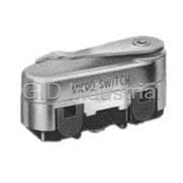
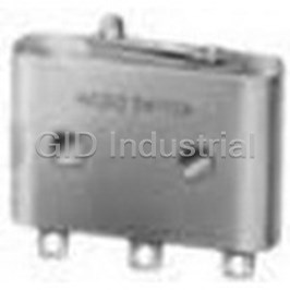
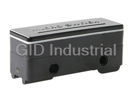
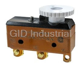
HONEYWELL BZ-2R24-A2

Description
Switch Snap Action N.O./N.C. SPDT Plunger Screw 16A 480VAC 250VDC 186.42VA 3.61N Screw Mount
BZ-2R24-A2
Part Number
BZ-2R24-A2
Price
Request Quote
Manufacturer
HONEYWELL
Lead Time
Request Quote
Category
Switches » Switch Snap Action
Specifications
Manufacturer
Honeywell
Manufacturers Part #
BZ-2R24-A2
Industry Aliases
BZ-2R24-A2
Sub-Category
Snap Action Switches
Brand
Micro Switch
Factory Pack Quantity
50
Datasheet

Extracted Text
MICRO SWITCH™ Premium Large Basic Switches BZ | BA | BM | BE | 6AS Series Datasheet MICRO SWITCH™ Large Premium Basic Switches Accurate, reliable, and repeatable, MICRO SWITCH™ BZ/BA/BM/BE Series features precise operating characteristics and enhanced life. These premium, large snap-action switches offer precision operation and sensitive differential travel. Utilizing state-of-the-art manufacturing processes and quality controls, Honeywell has engineered premium, large snap-action switches that meet various international agency requirements. Some models have military qualifications. MICRO SWITCH™ BZ/BA/BM/BE Series are often used for precision on/off applications, as well as end of limit, presence/absence, and manual operator interface functions. Their engineered design is suitable for various application needs. Configured options with BZ, BA, BM, and BE switches provide a wide variety of operating and interface characteristics. The MICRO SWITCH™ 6AS Series consists of two large premium BZ/BA/BM/BE snap-action switches ganged together and actuated by a single actuator. Field adjustable operating point is an option for one or both switches. What makes our switches better? • Industry-leading temperature range for options up to 204 °C [400 °F] and temperatures as low as -55 °C [-67 °F] • Exclusive current carrying capability of up to 25 A • International approvals: UL, CSA, ENEC, CE listings • Options for circuitry, styles, connection types and a wide selection of actuator styles • Dependable performance - tested up to 20 million mechanical cycles • MICRO SWITCH™ legacy and expertise - over 75 years of engineering excellence and experience Operating in extreme temperatures is all in a day’s work for MICRO SWITCH™ large basics! QUALITY • RELIABLE • RUGGED • GLOBAL sensing.honeywell.com 2 GLOBAL USE AND APPROVALS Features Switches certified to UL, CSA, ENEC, and CE for global use and Benefits FLEXIBILITY OF PRODUCT CHARACTERISTICS Honeywell’s large basic switches offer various operating force and differential travel options to meet the actuator type. Designed with momentary or maintained contact action, these switches may perform a variety of functions as well as offering a choice of actuation, termination and operating characteristics for design flexibility Listings certified for global use and mulitple applications VARIENTS FOR EXTREME CONDITIONS With an IP64 sealing option to maintain switch enclosure sealing, many listings can be used in dirty, harsh environments with their dustproof and splash resistant seals. Many versions operate in extreme temperatures, up to 121 °C [250 °F], and several with high temperature options for up to 204 °C [400 °F], as well as temperatures as low as -55 °C [-67 °F] EASY INSTALLATION REDUCES OVERALL COSTS The switch’s enlongated mounting hole allows for easier, more accurate mounting TIGHT HYSTERESIS/DIFFERENTIAL TRAVEL Designed with a hysteresis as small as 0,008 mm [0.0003 in], the BZ/BA/BM/ BE switches may be used in applications where very tight and sensitive control is required between the operate and release points Standardize switching packages CURRENT CAPACITY FROM LESS THAN 1 A TO 25 A With a broad current capacity, one switch package can control a wide range of electrical loads. As requirements vary for applications, a standardized switch package may help reduce costs and increase application flexibility. Gold contacts available for controlling low energy/low power circuits ENHANCED PERFORMANCE Internal flat spring design delivers optimum performance and switch reliability MILITARY APPROVALS MIL-PRF-8805 switches available for military-specified applications sensing.honeywell.com 3 Potential Applications BUILDING CONTROLS AND EQUIPMENT Often used in a building’s boiler/heater controls, in HVAC systems to sense exhaust pressure on high efficiency furnances, and in fire suppression systems to sound alarm when sprinkler activation/waterflow is detected. May also be used in machine tools to limit the maxiumum movement for pieces of equipment DOORS AND LIFTS May be used in elevators and lifts to sense if the car is in position before the door opens and on door-latching mechanisms to indicate door closed and/or door locked SEMI-TRUCKS AND TRAILERS Can be used to disengage the cruise control when the clutch pedal is depressed and for diesel engine brake assist. For surface transportation equipment, can be used as a seat switch VALVES Detects whether a valve is “open” or “closed” TIMING DEVICES Often used in commercial/industrial-grade timers to turn outputs “on” and/or “off” at preset times COMMUNICATION SYSTEMS May be used as a door interlock on communication consoles or enclosures FOOT SWITCHES In commerical and industrial foot switch enclosures, may be used as the switching element COMMERCIAL AND INDUSTRIAL KITCHEN EQUIPMENT May be used to indicate door closed and/or door locked for the self-cleaning feature IRRIGATION EQUIPMENT Often used for limiting maximum offset of irrigation towers MEDICAL INSTRUMENTATION In medical and dental equipment, often used in foot switches to control the dental drill and the positioning of the chair sensing.honeywell.com 4 MICRO SWITCH™ Premium Large Basic Switches Table 1. Specifications BZ WZ YZ BA WA YA Characteristic BM Series BE Series Series Series Series Series Series Series Ampere rating 15 A 20 A 22 A 25 A Circuitry SPDT SPNC SPNO SPDT SPNC SPNO SPDT SPDT Operating force 1.0 oz to 28 oz Termination quick connect, solder, screw Actuator pin plunger, overtravel plunger, straight, roller, flexible leaf roller, flexible leaf Voltage 125 Vac, 250 Vac, 125 Vdc, 250 Vdc Agency approvals UL, CSA, ENEC, CE (varies by specific model) Operating temperature -55 °C to 85 °C [-67 °F to 185 °F] Contacts silver, silver cadmium oxide, gold alloy Housing general purpose phenolic Sealing Environment sealing option available (options for IP64 Sealing) Dielectric strength 2000 V between each terminal and ground Contact resistance 15 m Ohm max.(initial) Insulation resistance 100,000 M Ohm min. Vibration 1,5 mm peak-to-peak amplitude, frequency 10 Hz to 55 Hz, for two continuous hours Expected mechanical life up to 20,000,000 cycles at 95% survival Expected electrical 100K operations at rated load service life Rated frequency 50 Hz/60 Hz sensing.honeywell.com 5 BZ | BA | BM | BE | 6AS Series ELECTRICAL DATA AND UL CODES GENERAL SWITCH IDENTIFICATION Table 2. UL Electrical Ratings The first letter in the catalog listing designates: Code Circuitry Electrical data and UL codes B = Single pole, double throw W = Single pole, normally closed 15 A, 125, 250 or 480 Vac; 1⁄8 HP, 125 Vac; 1⁄4 HP, 250 Vac; Y = Single pole, normally open A SPDT 1⁄2 A, 125 Vdc; 1⁄4 amp, 250 Vdc. UL Code L96 The second letter in the catalog listing designates: 5 A, 125, 250 or 480 Vac; Z = Standard, 15 A version B SPDT 1⁄2 A, 125 Vdc; 1⁄4 amp, 250 Vdc. M = 22 A version UL Code L35 A = Standard, 20 A version 10 A, 125, 250 or 480 Vac; C SPDT E = 25 A version UL Code L8 15 A, 125, 250 or 480 Vac; D SPDT 1⁄8 HP, 125 Vac; 1⁄4 HP, 250 Vac. MOUNTING DIMENSIONS UL Code L103 Mounting dimensions are included in this datasheet. They are 15 A, 125, 250 or 480 Vac; shown in English and metric equivalents. These dimensions are 1⁄4 HP, 125 Vac, 1⁄2 HP, 250 Vac; E SPDT for reference only. Engineering drawings may be accessed via the 1⁄2 A, 125 Vdc; 1⁄4 amp, 250 Vdc. Honeywell web site: sensing.honeywell.com. UL Code L67 22 A, 125, 250 or 480 Vac; Mounting holes for Types BZ, BM,BA, BE, and 6AS switches accept F SPDT 1⁄2 HP, 125 Vac, 1 HP, 250 Vac. UL Code L161 pins or screws of 3,53 mm [0.139 in] diameter. 20 A, 125, 250 or 480 Vac; 10 A, 125 Vac ‘‘L’’ (tungsten lamp load); G SPDT 1 HP, 125 Vac; 2 HP, 250 Vac; RECOMMENDED TORQUE 1⁄2 A, 125 Vdc; 1⁄4 A, 250 Vdc. UL Code L23 Mounting screws ........................0,39 Nm [3 in-lb]* Motor control - 25 A, 125, 250 or 480 Vac; Terminal screws. ......................... 0,45 Nm [4 in-lb] H SPDT 1 HP, 125 Vac; 2 HP, 250 Vac; Panel mount bushing .... 0,45 Nm to 0,68 Nm [4 in-lb to 6 in-lb] Pilot duty—750 VA, 125, 250, or 277 Vac 10 A, 125, 250 or 480 Vac; SPDT 1⁄8 HP, 125 Vac; 1⁄4 HP, 250 Vac; I *Note: Tightening mounting screws above 0,3 Nm [3 in-lb] changes UL Code L95 operating characteristics and increases the possibility of cracking 1 A, 125 Vac the case. P SPDT UL Code L22 Motor Control Two-circuit, 15 A, 120, 240, 480 or 600 Vac; UL/CSA T double 1⁄2 HP, 120 Vac; 1 HP, 240 Vac; break Honeywell basic switches are Component Recognized by 0.8 amp, 115 Vdc; 0.4 amp, 230 Vdc. Underwriters’ Laboratories, Inc. and certified by Canadian 20 A, 125, 250 or 277 Vac; Standards Association. The BA, BZ, and BM line is covered W SPST 3⁄4 HP, 125 Vac; 1⁄2 HP, 250 Vac UL Code L178B as Special Use Switches to UL Standard1054; the BE line is 15 A, 125, 250 or 480 Vac; covered as an Industrial Product to UL Standard 508. Agency File 2 A, 600 Vac; 1⁄8 HP, 125 Vac; References are: X SPDT 1⁄4 HP, 250 Vac; 1⁄2 amp, 125 Vdc; • BA UL File E12252, issued 12-09-88 1⁄4 amp, 250 Vdc. UL Code L74 • BM UL File E12252, issued 12-08-88 • BZ UL File E12252, issued 6-29-89 • BE-1,2,5 UL File E22779, Vol. 4, Sec. 1 • BE-R UL File E22779, Vol. 4, Sec. 2 sensing.honeywell.com 6 O.F. • Operating force MICRO SWITCH™ Premium Large Basic Switches R.F. • Release force P.T. • Pretravel O.T. • Overtravel D.T. • Differential travel O.P. • Operating position ORDER GUIDE BY ASCENDING ELECTRICAL CAPABILITY P.T. O.T. R.F. Catalog Recommended O.F. max. min. D.T. O.P.*** min. Listing For N [oz] mm mm mm [in] mm [in] N [ oz] [in] [in] 1 A 2,5 to 3,61 1,11 0,38 0,13 0,01 to 0,05 15,88 Applications requiring BZ-2R72-A2** gold alloy contacts P [9 to 13] [4] [0.015] [0.005] [0.0004 to 0.0020] [0.625] Gold alloy contacts 1 A 2,22 to 4,17 1,11 0,13 0,01 to 0,06 15,88 BZ-2R725551-A2 Dustproof and splash – P [8 to 15] [4] [0.005] [0.0004 to 0.0025] [0.625] resistant seal Operating in temp. to 5 A 2,5 to 3,61 1,11 0,38 0,13 0,01 to 0,05 15,88 BZ-2R244-A2 204 °C [400 °F] for BZ/BA type B [9 to 13] [4] [0.015] [0.005] [0.0004 to 0.0020] [0.625] 100 hours 10 A 1,11 0,7 0,30 0,13 0,005 to 0,013 15,88 BZ-R21-A2 Lower force C [4] [2.5] [0.012] [0.005] [0.0002 to 0.0005] [0.625] BZ/BA Type 15 A 2,5 to 3,61 1,11 0,38 0,13 0,01 to 0,05 15,88 Most applications BZ-2R-A2 SPDT A [9 to 13] [4] [0.015] [0.005] [0.0004 to 0.0020] [0.625] 15 A 2,5 to 3,61 1,11 0,38 0,13 0,01 to 0,05 15,88 SPST (normally WZ-2R-A2 closed) A [9 to 13] [4] [0.015] [0.005] [0.0004 to 0.0020] [0.625] 15 A 2,5 to 3,61 1,11 0,38 0,13 0,01 to 0,05 15,88 YZ-2R-A2 SPST (normally open) A [9 to 13] [4] [0.015] [0.005] [0.0004 to 0.0020] [0.625] 15 A 1,95 to 2.5 1,11 0,30 0,13 0,005 to 0,008 15,88 BZ-R-A2 Less differential travel D [7 to 9] [4] [0.012] [0.005] [0.0002 to 0.0003] [0.625] 0,13 to 0,2 15 A 1,95 to 3,34 1,11 0,30 0,005 to 0,02 16,26 BZ-R19-A2 Best repeatability [0.005 D [7 to 12] [4] [0.012] [0.0002 to 0.0008] [0.640] to 0.008] Sealed type 15 A 2,5 to 3,61 1,11 0,38 0,13 0,01 to 0,05 15,88 Operating in temp. to BZ-2R24-A2 121 °C [250 °F] A [9 to 13] [4] [0.015] [0.005] [0.0004 to 0.0020] [0.625] BZ-2RT04 15 A 2,5 to 3,61 1,67 0,38 0,13 0,01 to 0,05 15,88 MIL-PRF-8805 appli- Sealed type cation requirements (M8805/1-004) A [9 to 13] [6] [0.015] [0.005] [0.0004 to 0.0020] [0.625] 15 A 2,5 to 3,61 1,11 0,38 0,13 0,01 to 0,05 15,88 Stability under BZ-2R05-A2 varying humidity A [9 to 13] [4] [0.015] [0.005] [0.0004 to 0.0020] [0.625] 15 A 2,5 to 4,17 1,11 0,13 0,01 to 0,06 15,88 Dustproof and splash BZ-2R5551-A2 – resistant seal A [9 to 15] [4] [0.005] [0.0004 to 0.0025] [0.625] Sealed construction. 15 A 2,5 to 4,17 1,11 0,13 0,01 to 0,06 15,88 BZ-2R55-A2-S Stainless steel internal – A [9 to 15] [4] [0.005] [0.0004 to 0.0025] [0.625] snapspring 20 A 3,89 to 6,12 2,78 1,27 0,25 0,05 to 0,19 16,26 BA-2R-A2 Up to 20 ampere load G [14 to 22] [10] [0.050] [0.10] [0.0020 to 0.0075] [0.640] BA/BE type 20 A 3,89 to 6,12 2,78 1,27 0,25 0,05 to 0,19 16,26 Operating in temp. to BA-2R24-A2 121 °C [250 °F] G [14 to 22] [10] [0.050] [0.10] [0.0020 to 0.0075] [0.640] 22 A 1,95 to 2,78 1,11 0,38 0,13 0,013 to 0,025 15,88 BM-1R-A2 Up to 22 ampere load F [7 to 10] [4] [0.015] [0.005] [0.0005 to 0.0010] [0.625] 25 A 3,89 to 6,12 2,78 1,27 0,25 0,05 to 0,19 16,26 Up to 25 ampere load, BE-2R-A4 #8 screw terminals H [14 to 22] [10] [0.050] [0.10] [0.0020 to 0.0075] [0.640] 1,95 to 2,5 0,13 0,30 15 A [7 to 9] [0.005] 15,88 Manual reset, solder BZ-RX – [0.012] – Manual Reset terminals E 0,56 to 2,78* 0,38* [0.625] – [2 to 10] 0.015] 0,25 0,20 Manual reset 20 A 5,56 [20] 16,26 [0.64] WA-1RX-A4 SPST-NC, #8 screw – – [0.010] [0.008] W 6,95 [25]* 27,9*[1.10] terminals – – * Reset characteristics sensing.honeywell.com ** -A2 is supplied with #6 terminal screws 7 *** Except where stated, ±0,38 mm [±0.015 in] Electrical Data and UL Codes O.F. • Operating force BZ | BA | BM | BE | 6AS Series R.F. • Release force P.T. • Pretravel O.T. • Overtravel D.T. • Differential travel OVERTRAVEL PLUNGER ORDER GUIDE O.P. • Operating position P.T. O.T. R.F. Recommended O.F. max. min. D.T. O.P.* Catalog Listing min. For N [oz] mm mm mm [in] mm [in] N [ oz] [in] [in] 1 A 2,5 to 3,61 1,11 0,38 1,52 0,01 to 0,05 21,21 Applications requiring BZ-2RD72-A2 gold alloy contacts P [9 to 13] [4] [0.015] [0.060] [0.0004 to 0.0020] [0.835] Added overtravel. For 15 A 2,5 to 3,61 1,11 0,38 1,52 0,01 to 0,05 21,21 BZ-2RD-A2 manual operation and A [9 to 13] [4] [0.015] [0.060] [0.0004 to 0.0020] [0.835] slow 20° (max) cam rise 15 A 2,5 to 3,61 1,11 0,38 1,52 0,01 to 0,05 21,21 Operating in temperature BZ-2RD24-A2 to 121 °C [250 °F] A [9 to 13] [4] [0.015] [0.060] [0.0004 to 0.0020] [0.835] 22 A 1,95 to 2,78 1,11 0,38 1,52 0,013 to 0,025 21,21 BM-1RD-A2 Up to 22 ampere load F [7 to 10] [4] [0.015] [0.060] [0.0005 to 0.0010] [0.835] Applications requiring 1 A 3,61 to 5,28 1,11 1,52 0,01 to 0,063 28,20 gold alloy contacts plus BZ-2RDS725551-A2 – dustproof and splash P [13 to 19] [4] [0.060] [0.0004 to 0.0025] [1.110] resistant seal 15 A 3,61 to 5,28 1,11 1,52 0,01 to 0,063 28,20 Dustproof and splash BZ-2RDS5551-A2 – resistant seal A [13 to 19] [4] [0.060] [0.0004 to 0.0025] [1.110] 20 A 3,89 to 6,12 2,78 1,27 2,39 0,05 to 0,019 26,20 BA-2RB-A2 Up to 20 ampere load G [14 to 22] [10] [0.050] [0.094] [0.0020 to 0.0075] [1.03] 25 A 3,89 to 6,12 2,78 1,27 2,39 0,05 to 0,019 26,20 Up to 25 ampere load, BE-2RB-A4 #8 screw terminals H [14 to 22] [10] [0.050] [0.094] [0.0020 to 0.0075] [1.03] 1 A 2,5 to 3,61 1,11 0,38 1,52 0,01 to 0,05 28,20 Applications requiring BZ-2RS72-A2 gold alloy contacts P [9 to 13] [4] [0.015] [0.060] [0.0004 to 0.0020] [1.110] Added overtravel. For 15 A 2,5 to 3,61 1,11 0,38 1,52 0,01 to 0,063 28,20 BZ-2RS-A2 in-line operation and A [9 to 13] [4] [0.015] [0.060] [0.0004 to 0.0025] [1.110] with JR aux. actuators 15 A 2,5 to 3,61 1,11 0,38 1,52 0,01 to 0,05 28,20 Operating in temperature BZ-2RS24-A2 to 121 °C [250 °F] A [9 to 13] [4] [0.015] [0.060] [0.0004 to 0.0020] [1.110] MIL-PRF-8805 applica- 15 A 2,5 to 3,61 1,67 0,38 1,52 0,01 to 0,05 28,20 BZ-2RST04 tion (M8805/1-012) A [9 to 13] [6] [0.015] [0.060] [0.0004 to 0.0020] [1.110] requirements 15 A 1,95 to 2,64 0,30 0,65 2,79 Manual reset BZ-RSX – – solder terminals E [7 to 9] [0.012] [0.025] [1.11] 22 A 1,95 to 2,78 1,11 0,38 1,52 0,013 to 0,025 28,20 BM-1RS-A2 Up to 22 ampere load F [7 to 10] [4] [0.015] [0.060] [0.0005 to 0.0010] [1.110] Applications requiring gold 1 A 2,5 to 4,17 1,11 1,52 0,01 to 0,063 28,20 alloy contacts plus BZ-2RS7225551-A2 – dustproof and splash P [9 to 15] [4] [0.060] [0.0004 to 0.0025] [1.110] resistant seal 15 A 2,5 to 4,17 1,11 1,52 0,01 to 0,063 28,20 Dustproof and splash BZ-2RS5551-A2 – resistant seal A [9 to 15] [4] [0.060] [0.0004 to 0.0025] [1.110] * ±51 mm [±0.020 in] sensing.honeywell.com 8 Electrical Data and UL Codes O.F. • Operating force MICRO SWITCH™ Premium Large Basic Switches R.F. • Release force P.T. • Pretravel O.T. • Overtravel D.T. • Differential travel O.P. • Operating position OVERTRAVEL PLUNGER ORDER GUIDE P.T. O.T. R.F. Catalog Recommended O.F. max. min. D.T. O.P.** min. Listing For N [oz] mm mm mm [in] mm [in] N [ oz] [in] [in] Added overtravel. For 15 A 2,5 to 3,61 1,11 0,38 5,56 0,01 to 0,05 38,10 ±0,51 manual in-line operation BZ-2RQ-A2 and for slow 30° (max) A [9 to 13] [4] [0.015] [0.219] [0.0004 to 0.0020] [1.50 ±0.02] rise cams 15 A 2,5 to 3,61 1,11 0,38 5,56 0,01 to 0,05 38,10 ±0,51 Operating in temperature BZ-2RQ24-A2 to 121 °C [250 °F] A [9 to 13] [4] [0.015] [0.219] [0.0004 to 0.0020] [1.50 ±0.02] 1 A 2,5 to 3,61 1,11 0,38 5,56 0,01 to 0,05 21,82 Applications requiring BZ-2RQ172-A2 gold alloy contacts P [9 to 13] [4] [0.015] [0.219] [0.0004 to 0.0020] [0.859] 15 A 2,5 to 3,61 1,11 0,38 5,56 0,01 to 0,05 21,82 BZ-2RQ-A2 type applica- BZ-2RQ1-A2 tions with panel mount A [9 to 13] [4] [0.015] [0.219] [0.0004 to 0.0020] [0.859] 15 A 2,5 to 3,61 1,67 0,38 5,56 0,01 to 0,05 21,82 BZ-2RQ1T04 MIL-PRF-8805 application (M8805/1-020) requirements A [9 to 13] [6] [0.015] [0.219] [0.0004 to 0.0020] [0.859] 15 A 2,5 to 3,61 1,11 0,38 5,56 0,01 to 0,05 21,82 Operating in temperature BZ-2RQ124-A2 to 121 °C [250 °F] A [9 to 13] [4] [0.015] [0.219] [0.0004 to 0.0020] [0.859] Furnished with 15 A 2,5 to 3,61 1,11 0,38 3,18 0,01 to 0,05 48,4 ±0,50 BZ-2RN702 unassembled seal X [9 to 13] [4] [0.015] [0.125] [0.0004 to 0.0020] 1.906 [±0.02] boot. 23,42 ±1,14 [0.922 15 A 1,67 to 2,64 0,30 5,56 Manual reset. BZ-RQ1X – – ±0.045] Solder terminals E [6 to 9.5] [0.012] [0.219] 7,14* [0.281*] 20 A 3,89 to 6,12 2,78 1,27 5,56 0,05 to 0,19 21,82 BA-2RQ1-A2 Up to 20 ampere load G [14 to 22] [10] [0.050] [0.219] [0.0020 to 0.0075] [0.859] 22 A 1,95 to 2,78 1,11 0,38 5,56 0,013 to 0,025 21,82 BM-1RQ1-A2 Up to 22 ampere load F [7 to 10] [4] [0.015] [0.219] [0.0005 to 0.0010] [0.859] 1 A 2,5 to 3,61 1,11 0,38 3,56 0,01 to 0,05 33,32 ±1,14 Applications requiring gold BZ-2RQ1872-A2 alloy contacts P [9 to 13] [4] [0.015] [0.140] [0.0004 to 0.0020] [1.31 ±0.045] Added overtravel. Roller 15 A 2,5 to 3,61 1,11 0,38 3,56 0,01 to 0,05 33,32 ±1,14 plunger for rapid cam (30° BZ-2RQ18-A2 max) rise and slide A [9 to 13] [4] [0.015] [0.140] [0.0004 to 0.0020] [1.31 ±0.045] operation. Panel mount 15 A 2,5 to 3,61 1,11 0,38 3,56 0,01 to 0,05 33,32 ±1,14 Operating in temperature BZ-2RQ1824-A2 to 121 °C [250 °F] A [9 to 13] [4] [0.015] [0.140] [0.0004 to 0.0020] [1.31 ±0.045] 15 A 3,89 to 6,68 1,11 0,69 3,58 0,03 to 0,10 33,35 ±1,19 BZ-2AQ18T1 Double-break circuitry T [14 to 24] [4] [0.025] [0.141] [0.001 to 0.004] [1.31 ±0.047] 22 A 1,95 to 2,78 1,11 0,38 3,56 0,013 to 0,025 33,32 ±1,14 BM-1RQ18-A2 Up to 22 ampere load F [7 to 10] [4] [0.015] [0.140] [0.0005 to 0.0010] [1.31 ±0.045] Applications requiring 15 A 2,5 to 3,61 1,11 0,38 3,56 0,01 to 0,05 33,32 ±1,14 BZ-2RQ181-A2 roller plunger 90° to major A [9 to 13] [4] [0.015] [0.140] [0.0004 to 0.0020] [1.31 ±0.045] axis of switch * Reset characteristics ** Except where stated, ±0,76 mm [±0.030 in] sensing.honeywell.com 9 Electrical Data and UL Codes O.F. • Operating force BZ | BA | BM | BE | 6AS Series R.F. • Release force P.T. • Pretravel O.T. • Overtravel D.T. • Differential travel STRAIGHT LEVER ORDER GUIDE O.P. • Operating position P.T. O.T. R.F. Catalog Recommended O.F. max. min. D.T. O.P.** min. Listing For N [oz] mm mm mm [in] mm [in] N [ oz] [in] [in] Applications requiring gold 1 A 0,7 0,14 5,56 0,18 to 1,27 19,1 BZ-2RW8072-A2 – alloy contacts P [2.5] [0.5] [0.219] [0.007 to 0.050] [0.750] BZ- Stability under varying hu- 1 A 0,7 0,14 5,56 0,18 to 1,27 19,1 2RW80722555105- midity. Gold alloy contacts – P [2.5] [0.5] [0.219] [0.007 to 0.050] [0.750] A2 with seal Operating in temp. 5 A 0,7 0,14 5,56 0,18 to 1,27 19,1 BZ-2RW8244-A2 to 204 °C [400 °F] – B [2.5] [0.5] [0.219] [0.007 to 0.050] [0.750] for 100 hours Lowest operating 10 A 0,07 6,76 5,56 0,08 to 0,38 19,1 BZ-RW8435-A2 force (without external – I [0.25[ [0.266] [0.219] [0.003 to 0.015] [0.750] return spring) 15 A 1,67 0,42 0,42 0,10 to 0,63 19,1 BZ-2RW876T 1.25-inch lever – A [6] [1.5] [0.141] [0.004 to 0.025] [0.750] 15 A 0,7 0,14 5,56 0,18 to 1,27 19,1 BZ-2RW80-A2 2.5-inch lever – A [2.5] [0.5] [0.219] [0.007 to 0.050] [0.750] 15 A 0,28 0,03 8,33 5,56 0,18 to 1,27 19,1 Lower force (without BZ-2RW84-A2 external return spring) A [1] [0.125] [0.328] [0.219] [0.007 to 0.050] [0.750] 15 A 0,7 0,14 5,56 0,18 to 1,27 19,1 BZ-2RW805551- Dustproof and – A2 splash resistant seal A [2.5] [0.5] [0.219] [0.007 to 0.050] [0.750] 15 A 0,28 to 0,90 0,21 7,52 4,37 2,36 19,1 BZ-2RWT04 MIL-PRF-8805 (M8805/1-044) application requirements A [1 to 3.25] [0.75] [0.296] [0.172] [0.093] [0.750] 15 A 0,7 0,14 5,56 0,18 to 1,27 19,1 Operating in temperature BZ-2RW824-A2 – to 121 °C [250 °F] A [2.5] [0.5] [0.219] [0.007 to 0.050] [0.750] 5,56 19,05 15 A 0,63 [0.219] [0.750] Manual reset, solder BZ-RW80X – – – terminals E [2.25] 0,38* 7,14* [0.015] [0.281] 15 A 0,28 12,7 0,46 to 3,68 19,1 ±1,52 BZ-2RW863-A2 6-inch lever – – A [1] [0.50] [0.018 to 0.145] [0.75 ±0.06] 20 A 0,7 0,14 15,88 1,98 2,77 max. 19,1 BA-2RV-A2 Up to 20 ampere load G [2.5] [0.5] [0.625] [0.078] [0.109] max. [0.750] 22 A 0,28 0,03 7,54 5,56 0,13 to 0,84 19,1 BM-1RW84-A2 Up to 22 ampere load F [1] [0.125] [0.297] [0.219] [0.005 to 0.033] [0.750] 25 A 0,7 0,14 15,88 1,98 2,77 max. 19,1 Up to 25 ampere load BE-2RV-A4 #8 screw terminals H [2.5] [0.5] [0.625] [0.078] [0.109] max. [0.750] 17,02 to Adjustable operating point 15 A 0,7 0,14 3,54*** 0,18 to 1,27 22,35 BZ-2RW899-A2 17 mm to 22 mm [0.67 in – A [2.5] [0.5] [0.125] [0.007 to 0.050] [0.670 to to 0.88 in] 0.880] Reverse acting actuator 15 A 1,67 0,28 5,56 5,56 0,10 to 0,89 19,1 BZ-2RM-A2 (switch plunger depressed A [6] [1] [0.219] [0.219] [0.004 to 0.035] [0.750] in free position) * Reset characteristics ** except where stated ±0,76 mm [±0.030 in] *** from 17 mm [0.670 in] O.P. sensing.honeywell.com 10 Electrical Data and UL Codes O.F. • Operating force MICRO SWITCH™ Premium Large Basic Switches R.F. • Release force P.T. • Pretravel O.T. • Overtravel D.T. • Differential travel O.P. • Operating position SIMULATED ROLLER AND ROLLER LEVER ORDER GUIDE P.T. O.T. R.F. Catalog Recommended O.F. max. min. D.T. O.P.** min. Listing For N [oz] mm mm mm [in] mm [in] N [ oz] [in] [in] 1.05 inch (26,7 mm) 15 A 1,67 0,42 2,39 0,08 to 0,51 30,17 BZ-2RW80147- (simulated roller) – A2 A [6] [1.5] [0.094] [0.003 to 0.020] [1.188] lever applications 30,17 ±0,76 1.90 inch (48,3 mm) 15 A 0,97 0,21 3,96 0,10 to 1,0 BZ-2RW80196-A2 (simulated roller) – [1.188 A [3.5] [0.75] [0.156] [0.004 to 0.040] lever applications ±0.03] Applications 1 A 1,67 0,42 2,39 0,08 to 0,51 30,17 BZ-2RW82272- requiring gold alloy – A2 P [6] [1.5] [0.094] [0.003 to 0.020] [1.188] contacts BZ- Apps requiring gold alloy 1 A 1,67 0,42 2,39 0,08 to 0,51 30,17 2RW822725551- contacts plus dustproof – P [6] [1.5] [0.094] [0.003 to 0.020] [1.188] A2 and splash resistant seal 15 A 1,67 0,42 2,39 0,08 to 0,51 30,17 26,7 mm [1.05 in] mm) BZ-2RW822-A2 – roller lever A [6] [1.5] [0.094] [0.003 to 0.020] [1.188] 3,58 15 A 0,7 to 1,81 0,35 0,08 to 0,51 30,75 BZ-2RW8222-A2 Roller turned 90° – [0.141] A [2.5 to 6.5] [1.25] [0.003 to 0.020] [1.25] max. Operating in 15 A 1,67 0,42 2,39 0,08 to 0,51 30,17 BZ-2RW82224- temperature to – A2 A [6] [1.5] [0.094] [0.003 to 0.020] [1.188] 121 °C [250 °F] 15 A 1,67 0,42 2,39 0,08 to 0,51 30,17 BZ- Dustproof and – 2RW8225551-A2 splash resistant seal A [6] [1.5] [0.094] [0.003 to 0.020] [1.188] Best service for BZ- sealed construction. 15 A 1,67 0,42 2,39 0,08 to 0,51 30,17 – 2RW82255-A2-S Stainless steel A [6] [1.5] [0.094] [0.003 to 0.020] [1.188] internal snap spring. 20 1,67 0,42 6,35 0,76 1,14 29,77 BA-2RV22-A2 Up to 20 ampere load G [6] [1.5] [0.250] [0.030] [0.045] max. [1.172] 22 1,67 0,42 2,39 0,025 to 0,33 30,17 BM-1RW822-A2 Up to 22 ampere load – F [6] [1.5] [0.094] [0.001 to 0.013] [1.188] Up to 25 ampere load, 25 1,67 0,42 6,35 0,76 1,14 29,77 BE-2RV22-A4 #8 screw terminals H [6] [1.5] [0.250] [0.030] [0.045] max. [1.172] 29,77 to Adjustable operating 15 A 1,67 0,42 1,02 0,08 to 0,51 30,56 BZ-2RW82299- point. Roller lever – A2 A [6] [1.5] [0.040] [0.003 to 0.020] [1.172 to 1.05 inch (26,7 mm) 1.203] 29,2 to 31,5 Adjustable operating 15 A 0,97 0,21 2,16 0,10 to 1,0 BZ-2RW8299-A2 point. Roller lever – [1.150 to A [3.5] [0.75] [0.085] [0.004 to 0.040] 1.90 inch (48,3 mm) 1.24] ** except where stated ±0,38 mm [±0.015 in] sensing.honeywell.com 11 Electrical Data and UL Codes O.F. • Operating force BZ | BA | BM | BE | 6AS Series R.F. • Release force P.T. • Pretravel O.T. • Overtravel D.T. • Differential travel ROLLER LEVER ORDER GUIDE O.P. • Operating position P.T. O.T. R.F. Catalog Recommended O.F. max. min. D.T. O.P.** min. Listing For N [oz] mm mm mm [in] mm [in] N [ oz] [in] [in] Applications requiring 30,17 ±0,76 BZ- 1 A 0,97 0,21 3,96 0,10 to 1,0 gold alloy contacts, 2RW82725551- – [1.188 plus dustproof, and P [3.5] [0.75] [0.156] [0.004 to 0.040] A2 ±0.030] splash resistant seal 30,17 ±0,76 1.90 inch (48,3 mm) 15 A 0,97 0,21 3,96 0,10 to 1,0 BZ-2RW82-A2 (steel roller) lever – [1.188 A [3.5] [0.75] [0.156] [0.004 to 0.040] applications ±0.030] 30,17 ±0,76 15 A 0,97 0,21 3,96 0,10 to 1,0 BZ-2RW825551- Dustproof and splash – [1.188 A2 resistant seal A [3.5] [0.75] [0.156] [0.004 to 0.040] ±0.030] 30,17 ±0,76 15 A 0,97 0,21 3,96 0,10 to 1,0 Operating in temperature BZ-2RW8224-A2 – [1.188 to 121 °C [250 °F] A [3.5] [0.75] [0.156] [0.004 to 0.040] ±0.030] 30,17 ±0,76 20 A 0,97 0,14 11,89 1,52 2,16 BA-2RV2-A2 Up to 20 ampere load [1.188 G [3.5] [0.5] [0.468] [0.060] [0.085] ±0.030] 30,17 ±0,76 22 A 0,97 0,21 3,96 0,08 to 0,56 BM-1RW82-A2 Up to 22 ampere load – [1.188 F [3.5] [0.75] [0.156] [0.003 to 0.022] ±0.030] 30,17 ±0,76 25 A 0,97 0,14 11,89 1,52 2,16 Up to 25 ampere load, BE-2RV2-A4 [1.188 #8 screw terminals H [3.5] [0.5] [0.468] [0.060] [0.085] ±0.030] 10 A 3,34 1,11 0,35 2,54 0,013 to 0,025 31,37 Best repeatability and BZ-RW922-A2 O.P. stability I [12] [4] [0.015] [0.100] [0.0005 to 0.0010] [1.235] One-way roller 9,4 15 A 1,67 0,42 2,39 0,08 to 0,51 41,34 BZ-2RW826-A2 mm x 3,8 mm [0.37 in – A [6] [1.5] [0.094] [0.003 to 0.020] [1.625] dia. x 0.15 in] wide roller One-way roller 4,83 15 A 2,22 0,42 1,52 0,38 28,96 BZ-2RW825-A2 mm x 4,83 mm [0.19 in – A [8] [1.5] [0.060] [0.015] [1.14] dia. x 0.19 in] wide roller NOTE: For adjustable operate point and simulated roller lever switches, refer to previous page. ** except where stated ±0,38 mm [±0.015 in] sensing.honeywell.com 12 Electrical Data and UL Codes O.F. • Operating force MICRO SWITCH™ Premium Large Basic Switches R.F. • Release force P.T. • Pretravel O.T. • Overtravel D.T. • Differential travel O.P. • Operating position FLEXIBLE LEAF AND FLEXIBLE ROLLER LEAF ORDER GUIDE P.T. O.T. R.F. D.T. Catalog Recommended O.F. max. min. O.P.** min. mm [in] Listing For N [oz] mm mm mm [in] N [ oz] max. [in] [in] 15 A 1,39 0,14 1,52 1,27 17,48 Force and stability of the BZ-2RL-A2 – flexible leaf actuator A [5] [0.5] [0.060] [0.050] [0.688] 15 A 1,95 0,14 1,52 1,27 17,48 Dustproof and splash BZ-2RL5551-A2 – resistant seal A [7] [0.5] [0.060] [0.050] [0.688] BZ-2RLT04 MIL-PRF-8805 application 15 A 1,39 0,14 1,52 1,27 17,48 – (M8805/1-001) requirements A [5] [0.5] [0.060] [0.050] [0.688] Operating in temperature 15 A 1,39 0,14 1,52 1,27 17,48 BZ-2RL24-A2 – to 121 °C [250 °F] A [5] [0.5] [0.060] [0.050] [0.688] 1,57 17,48 Manual reset. 15 A 0,83 [0.062] [0.688] BZ-RLX – – – Solder terminals E [3] 0,38* 7,14* [0.015] [0.281] 20 A 2,5 0,28 1,57 1,57 17,48 BA-2RL-A2 Up to 20 ampere load – G [9] [1] [0.062] [0.062] [0.688] 25 A 2,5 0,28 1,57 1,57 17,48 Up to 25 ampere load, BE-2RL-A4 – #8 screw terminals H [9] [1] [0.062] [0.062] [0.688] 5 A 1,39 0,14 1,52 1,27 28,6 Operating in temp. to 121 BZ-RL24-A2 – °C [250 °F] for 100 hours B [5] [0.5] [0.060] [0.050] [1.125] 15 A 1,39 0,14 1,52 1,27 28,6 Force and stability of the BZ-2RL2-A2 – flexible leaf with roller A [5] [0.5] [0.060] [0.050] [1.125] 15 A 1,95 0,14 1,52 1,27 28,6 BZ-2RL25551- Dustproof and splash – A2 resistant seal A [7] [0.5] [0.060] [0.050] [1.125] 15 A 1,04 to 1,39 0,14 1,52 1,27 28,6 BZ-2RL2T04 MIL-PRF-8805 application – (M8805/1-036) requirements A [3.75 to 5] [0.5] [0.060] [0.050] [1.125] 20 A 2,5 0,28 1,52 1,65 28,6 BA-2RL2-A2 Up to 20 ampere load – G [9] [1] [0.060] [0.065] [1.125] 25 A 2,5 0,28 1,52 1,65 28,6 Up to 25 ampere load, BE-2RL2-A4 – #8 screw terminals H [9] [1] [0.060] [0.065] [1.125] NOTE: For adjustable operate point and simulated roller lever switches, refer to previous page. ** except where stated ±0,76 mm [±0.030 in] sensing.honeywell.com 13 Electrical Data and UL Codes BZ | BA | BM | BE | 6AS Series STANDARD ACTUATOR OPTIONS, TERMINALS, & DIMENSIONS BZ/BM Series: Pin plunger BA/BE Series: Pin plunger 2,3 mm [0.09 in] dia 2,3 mm [0.09 in] dia 0,2 mm 1,27 mm [0.01 in] SST plunger [0.05 in] SST plunger 23,37 mm P.T. P.T. 19,05 mm [0.75 in] [0.92 in] 16,2 mm 15,7 mm 15,0 mm 15,0 mm [0.64 in] 5,3 mm [0.62 in] [0.59 in] [0.21 in] [0.59 in] O.P. O.P. 9,1 mm 9,1 mm [0.36 in] [0.36 in] 3,6 mm 3,6 mm [0.14 in] [0.14 in] 4,3 mm 3,6 mm 25,4 mm 4,3 mm 3,6 mm [0.17 in] [0.14 in] 25,4 mm [1.00 in] [0.17 in] dia. [0.14 in] dia. [1.00 in] dia. dia. 49,3 mm 49,3 mm [1.94 in] [1.94 in] BZ/BM Series: Overtravel plunger BA/BE Series: Overtravel plunger 12,7 mm 0,25 mm Plated steel plunger 7,1 mm [0.05 in] [0.01 in] 15,0 mm [0.59 in] dia. [0.28 in] 7,11 mm [0.28 in] dia. max. max. 13,5 mm dia. P.T. P.T. SST plunger [0.53 in] 4,06 mm 23,37 mm dia. [0.16 in] [0.92 in] 19,05 mm 7,62 mm [0.75 in] [0.30 in] 26,1 mm 21,1 mm [1.03 in] [0.83 in] 14,5 mm O.P. 14,9 mm 5,3 mm O.P. [0.57 in] [0.59 in] [0.21 in] 9,1 mm 9,1 mm [0.36 in] 3,6 mm [0.36 in] 3,6 mm [0.14 in] [0.14 in] 4,3 mm 3,6 mm 3,6 mm 4,3 mm 25,4 mm 25,4 mm [0.17 in] [0.17 in] [0.14 in] [0.14 in] [1.00 in] [1.00 in] dia. dia. dia. dia. 49,3 mm 49,3 mm [1.94 in] [1.94 in] BZ/BM Series: Bushing-mount overtravel plunger BA/BE Series: Bushing-mount overtravel plunger Plated steel plunger Plated steel plunger 8,1 mm 8,1 mm [0.32 in] [0.32 in] dia. dia. 0,2 mm 21,8 mm 1,27 mm 21,8 mm [0.86 in] [0.01 in] [0.05 in] [0.86 in] O.P. 13,2 mm 13,2 mm max. max. O.P. [0.52 in] P.T. [0.52 in] P.T. 16,0 mm 16,0 mm 14,5 mm 5,3 mm 14,5 mm 5,3 mm 23,37 mm [0.92 in] 19,05 mm [0.75 in] [0.63 in] [0.63 in] [0.57 in] [0.21 in] [0.57 in] [0.21 in] 9,1 mm 9,1 mm [0.36 in] [0.36 in] 3,6 mm 3,6 mm [0.14 in] [0.14 in] 25,4 mm 25,4 mm 4,3 mm 3,6 mm 4,3 mm 3,6 mm [1.00 in] [0.17 in] [1.00 in] [0.14 in] [0.17 in] [0.14 in] dia. dia. dia. dia. 49,3 mm 49,3 mm [1.94 in] [1.94 in] sensing.honeywell.com 14 11,9 mm 11,9 mm [0.47 in] 11,9 mm [0.47 in] [0.47 in] 11,9 mm 11,9 mm 11,9 mm [0.47 in] [0.47 in] [0.47 in] MICRO SWITCH™ Premium Large Basic Switches STANDARD ACTUATOR OPTIONS, TERMINALS, & DIMENSIONS BZ/BM Series: Flexible leaf actuator BA/BE Series: Flexible leaf actuator 45,2 mm 49,5 mm [1.95 in] [1.78 in] SST lever SST lever 25,4 mm 20,5 mm 17,5 mm 17,5 mm [1.00 in] [0.81 in] [0.69 in] 5,3 mm 14,7 mm 14,7 mm [0.69 in] 5,3 mm F.P. F.P. O.P. [0.21 in] [0.58 in] O.P. [0.58 in] [0.21 in] 9,1 mm 9,1 mm [0.36 in] [0.36 in] 3,6 mm 3,6 mm [0.14 in] [0.14 in] 4,3 mm 3,6 mm 4,3 mm 3,6 mm 25,4 mm 25,4 mm [0.17 in] [0.14 in] [0.17 in] [0.14 in] [1.00 in] [1.00 in] dia. dia. dia. dia. 49,3 mm 49,3 mm [1.94 in] [1.94 in] BZ/BM Series: Straight lever with external return spring BA/BE Series: Straight lever 9,6 mm [0.38 in] 9,6 mm [0.38 in] 63,5 mm 63,5 mm [2.50 in] [2.50 in] R R SST lever SST lever 34,8 mm 27,2 mm [1.37 in] 20,0 mm [1.07 in] 20,8 mm 19,0 mm 19,1 16,5 mm F.P. 16,8 mm [0.79 in] [0.82 in] 5,3 mm [0.75 in] 5,3 mm F.P. 0.75 [0.66 in] [0.69 in] F.P. [0.21 in] O.P. [0.21 in] O.P. 9,1 mm 9,1 mm [0.36 in] [0.36 in] 3,6 mm 3,6 mm [0.14 in] [0.14 in] 3,6 mm 25,4 mm 4,3 mm [0.14 in] 25,4 mm 4,3 mm [1.00 in] 3,6 mm [0.17 in] dia. [1.00 in] [0.17 in] [0.14 in] 49,3 mm dia. dia. 49,3 mm dia. [1.94 in] [1.94 in] BZ/BM Series: Roller lever with external return spring Pin plunger with manual reset 25,9 mm 2,3 mm [0.09 in] dia [1.02 in] SST plunger 19,05 mm [0.75 in] 9,7 mm SST roller 26,7 mm [0.38 in] [1.05 in] 16,2 mm 5,3 mm 14,9 mm [0.64 in] R [0.21 in] [0.59 in] O.P. 32,0 mm 11,9 mm [1.26 in] 20,0 mm 29,9 mm 3,6 mm [0.47 in] F.P. [0.79 in] 5,3 mm [1.18 in] [0.14 in] 28,7 mm O.P. [0.21 in] 27,9 mm [1.13 in] 3,6 mm [1.10 in] F.P. [0.14 in] 9,1 mm R.O.P. [0.36 in] dia. 3,6 mm 9,6 mm [0.14 in] [0.38 in] 25,4 mm 25,4 mm 4,3 mm 3,6 mm [1.00 in] [1.00 in] [0.17 in] [0.14 in] dia. dia. 49,3 mm 49,3 mm [1.94 in] [1.94 in] sensing.honeywell.com 15 11,9 mm 11,9 mm [0.47 in] [0.47 in] 11,9 mm [0.47 in] 11,9 mm 11,9 mm [0.47 in] [0.47 in] 11,9 mm [0.47 in] BZ | BA | BM | BE | 6AS Series 6AS SERIES - PREMIUM LARGE SNAP-ACTION TANDEM SWITCH ASSEMBLY The MICRO SWITCH™ 6AS Series consists of two large premium BZ/BA/BM/BE snap-action switches ganged together and actuated by a single actuator. Operating characteristics are dependent upon the type of individual switches and actuators chosen. Field adjustable operat- ing point on one or both basic switches. Solder, A2, and T-type terminations available, along with straight, roller, and leaf levers. Mounting holes accept pins or screws of 3,53 mm [0.139 in] diameter. Often used for boiler controls or anywhere two circuits need to be controlled by one actuator. O.F. • Operating force R.F. • Release force O.T. • Overtravel D.T. • Differential travel 6AS SERIES ORDER GUIDE O.P. • Operating position Recommended O.F. R.F. min. O.T. min. D.T. O.P.* For N [oz] N [ oz] mm [in] mm [in] mm [in] Centered lever. Adjustment 15 A 30,56 mm 0,51 2,77 29,77 6AS34 A2 2,22 [8] 0,14 [0.5] over switch D A [1.203 in] [0.020] [0.109] [1.172] Lever over switch C. 15 A 30,56 mm 0,51 2,77 29,77 6AS36 A2 2,22 [8] 0,14 [0.5] Adjustment over switch D A [1.203 in] [0.020] [0.109] [1.172] 30,96 20 A 30,56 mm 1,02 3,96 ±1,14 Centered lever. Adjustment 6AS16 A2 3,89 [14] 1,11 [4] over switch D G [1.203 in] [0.040] [0.156] [1.219 ±0.045] A2 and D6 Lever over switch C. 15 A 26,67 mm 2,4 1,3 30,2 6AS201 No adjustment. Sealed 6,35 mm x 4,2 [15] 0,42 [1.5] A [1.05 in] [0.094] [0.050] [1.188] construction 0,81 mm [0.25 in x 0.32 in] 0,76 to Centered leaf. No adjust- 15 A 38,38 1,52 ment. Switches operate 6AS5 A2 – – – – within 0.030 in of each A [1.51] [0.030 to other 0.060] 20 A 32,26 1,02 18,67 Centered lever. Adjustment 6AS28 A2 3,89 [14] 1,11 [4] – over switch C G [1.27] [0.040] [0.735] * except where stated ±0,76 mm [±0.030 in] sensing.honeywell.com 16 Catalog Listing Electrical Data and UL Codes Lever length Terminal type MICRO SWITCH™ Premium Large Basic Switches STANDARD ACTUATOR OPTIONS, TERMINALS, & DIMENSIONS 6AS Series: Straight Lever 6AS Series: Leaf actuator 6AS Series: Roller Lever sensing.honeywell.com 17 BZ | BA | BM | BE | 6AS Series OPERATING CHARACTERISTICS Table 3. Operating Characteristics Definitions Characteristic Description Differential Travel-DT Plunger or actuator travel from point where contacts “snap-over” to point where they “snap-back.” Free Position-FP Position of switch plunger or actuator when no external force is applied. Full Overtravel Force Force required to attain full overtravel of actuator. Position of switch plunger or actuator at which point contacts snap from normal to operated position. With Operating Position-OP flexible or adjustable actuators, the operating position is measured from the end of the lever or its maximum length. Location of operating position measurement shown on mounting dimension drawings. Amount of force applied to switch plunger or actuator to cause the contact “snap-over.” Note in the case of Operating Force-OF adjustable actuators, the force is measured from the maximum length position of the lever. Overtravel-OT Plunger or actuator travel safely available beyond operating position. Pretravel-PT Distance or angle traveled in moving plunger or actuator from free position to operating position. Amount of force still applied to switch plunger or actuator at the moment contacts snap from operated position Release Force-RF to non-operated position. Total Travel Distance from actuator free position to overtravel limit position. sensing.honeywell.com 18 MICRO SWITCH™ Premium Large Basic Switches AVAILABLE TERMINALS ACTUATORS BA, BE, BM, and BZ standard snap-action switches use the actuators described: sensing.honeywell.com 19 BZ | BA | BM | BE | 6AS Series LARGE PREMIUM SWITCH SERIES NOMENCLATURE TREE (NOT ALL CONFIGURATIONS AVAILABLE) sensing.honeywell.com 20 – – – substitute W Series for SPNC circuitry substitute Y Series for SPNO circuitry 90° QC used with flat base MICRO SWITCH™ Premium Large Basic Switches LARGE SNAP-ACTION SWITCH ACCESSORIES Brackets Description 8MA1 8MA2 17MA1-B Description Adjustable mounting bracket with Adjustable mounting bracket with Conversion mounting bracket adjustment slot on left adjustment slot on right Housing material Steel Steel Corrosion-resistant metal Measurements 60,2 mm W x 21,3 mm H x 7,4 mm D [2.37 in W x 0.84 in H x 0.29 in D] 66,8 mm W x 19,0 mm D [2.63 in W x 0.75 in D] Features sturdy plated steel construction; fast, easy screwdriver adjustment; can be used converts standard basic switches from side to top mount; corrosion resist- with most standard basic switches ant; snaps into switch mounting holes without tools Die-cast Zinc Enclosures Description 3PA1 3PA28 3PA2 Description mounted from either side through 3,55 mounted from either side through 3,55 switch secured in enclosure; two 4,37 mm [0.140 in] dia. holes on 25,4 mm mm [0.140 in] dia. holes on 25,4 mm mm [0.172 in] dia. holes in flange ac- [1.0 in] centers; conduit/hub 0.5 – 14 [1.0 in] centers. 1/2-14 NPSM internal cept #8 screws for mounting on 41,3 NPT internal thread thread conduit hub mm [1.625 in] centers; conduit/hub 0.5 – 14 NPT internal thread Housing material die-cast zinc enclosure (side mount) die-cast zinc enclosure (side mount) die-cast zinc enclosure (flange mount) Measurements 74,8 mm W x 42,9 mm H x 25,4 mm D 74,8 mm W x 42,9 mm H x 25,4 mm D 74,8 mm W x 42,9 mm H x 25,4 mm D [2.95 in W x 1.69 in H x 1.00 in D] [2.95 in W x 1.69 in H x 1.00 in D] [2.95 in W x 1.69 in H x 1.00 in D] Sealing/Features NEMA 1; IP 40; protects the switch from physical abuse and personnel from contact with exposed terminals Plastic Thermal Enclosures Description 5PA1 5PA2 5PA3 Description Plastic terminal enclosure used with Plastic terminal enclosure use with Plastic terminal enclosure used with solder terminal switches screw terminal switches either solder or screw terminal switches with auxiliary actuators assembled Housing material plastic plastic plastic Measurements 52,8 mm W x 16,1 mm H 52,8 mm W x 20,2 mm H x 21,0 mm D 52,8 mm W x 20,2 mm H x 21,0 mm D [2.08 in W x 0.80 in H x 0.83 in D] [2.08 in W x 0.64 in H] [2.08 in W x 0.80 in H x 0.83 in D] Sealing/Features NEMA 1, IP 40; easy to use; screw and solder terminal versions; protect personnel from contact with exposed terminals sensing.honeywell.com 21 BZ | BA | BM | BE | 6AS Series AUXILIARY ACTUATOR ORDER GUIDE Use Catalog Overtravel min. Operating Position* Free Position Description only Listing mm [in] mm [in] mm [in] with Roller lever for “S” plunger 44,45 mm ±3,18 mm JR type BZ switches only. Permits BZ 11,1 mm [0.437 in] – [1.75 in ±0.125 in] cam operation 39,6 mm to 43,7 AD5721R 11,1 mm [0.437 in] 31,75 mm to 41,15 mm (M8805/59) BZ, BM mm [1.56 in to Adjustable roller lever. Tang on approx. [1.25 in to 1.62 in] AN3169-1 1.72 in] top of actuator can be bent to adjust O.P. and F.P. 9,53 mm [0.375 in] 40,48 mm 46,03 mm ADA3721R BA, BE approx. [1.594 in] approx. [1.812 in] MC2711 (M8805/59) BZ, BM 4,78 mm [0.188 in] 27,79 mm [1.094 in] 29,4 mm [1.156 in] AN3168-2 Straight plunger. Panel mount 30,18 mm MCA2711 BA, BE 3,96 mm [0.156 in] 28,17 mm [1.109 in] [1.188 in] 29,4 mm MC2711H BZ, BM 4,78 mm [0.188 in] 28,98 mm [1.141 in] Sealed straight plunger. Panel [1.156 in] mount. Elastomer boot seal resists liquid splash and dirt. 27,38 mm ±0,76 mm 29,56 mm MCA2711H BA, BE 4,37 mm [0.172 in] Furnished unassembled. [1.078 in ±0.030 in] [1.156] 3,18 mm [0.125 in] 37,69 mm MD3211Q BZ, BM 35,7 mm [1.406 in] approx. [1.484 in] Roller plunger. Panel mount. Roller parallel to long axis of 37,69 mm the switch MDA3711Q BA, BE 3,18 mm [0.125 in] 36,12 mm [1.422 in] [1.484 in] 3,18 mm [0.125 in] 37,69 mm MD3211Q1 BZ, BM 35,7 mm [1.406 in] approx. [1.484 in] Cross roller plunger. Panel mount. Roller perpendicular to 37,69 mm long axis of the switch MDA3711Q1 BA, BE 3,18 mm [0.125 in] 36,12 mm [1.422 in] [1.484 in] MC7711 20,62 mm 70,64 mm (M8805/58) BZ, BM 69,1 mm [2.719 in] [0.812 in] [2.781 in] AN3167-1 High overtravel plunger. Panel mount 19,84 mm 71,42 mm MCA7711 BA, BE 69,44 mm [2.734 in] [0.781 in] [2.812 in] * except where stated ±1,14 mm [±0.045 in] NOTE: All actuators are for use with pin plunger types only, except catalog listing JR. sensing.honeywell.com 22 ADDITIONAL INFORMATION WARNING The following associated literature is available at PERSONAL INJURY sensing.honeywell.com: DO NOT USE these products as safety or emergency stop • Product installation instructions devices or in any other application where failure of the • Product application-specific information product could result in personal injury. – Sensors and switches for potential HVAC/R applications Failure to comply with these instructions could result in – Sensors and switches for valve monitors and valve indicators death or serious injury. – Sensors and switches in oil rig applications – Sensors and switches in sanitary valves WARNING • Case study MISUSE OF DOCUMENTATION – A good range of mobility - BZ Series • The information presented in this product sheet is for reference only. Do not use this document as a product • BZ/BA performance information installation guide. • Applying basic switches • Complete installation, operation, and maintenance • Low energy switching guide information is provided in the instructions supplied with each product. • Product range guide Failure to comply with these instructions could result in death or serious injury. WARRANTY/REMEDY Honeywell warrants goods of its manufacture as being free of defective materials and faulty workmanship. Honeywell’s standard product warranty applies unless agreed to otherwise by Honeywell in writing; please refer to your order acknowledgement or consult your local sales office for specific warranty details. If warranted goods are returned to Honeywell during the period of coverage, Honeywell will repair or replace, at its option, without charge those items it finds defective. The foregoing is buyer’s sole remedy and is in lieu of all other warranties, expressed or implied, including those of merchantability and fitness for a particu- Find out more lar purpose. In no event shall Honeywell be liable for conse- Honeywell serves its customers quential, special, or indirect damages. through a worldwide network of sales offices, representatives While we provide application assistance personally, through our and distributors. For application literature and the Honeywell website, it is up to the customer to assistance, current specifications, determine the suitability of the product in the application. pricing or name of the nearest Authorized Distributor, contact Specifications may change without notice. The information we your local sales office. supply is believed to be accurate and reliable as of this printing. However, we assume no responsibility for its use. To learn more about Honeywell’s sensing and control products, call +1-815-235-6847 or 1-800-537-6945, visit sensing.honeywell.com, or e-mail inquiries to info.sc@honeywell.com Sensing and Productivity Solutions Honeywell 1985 Douglas Drive North 004955-5-EN IL50 GLO Golden Valley, MN 55422 December 2015 honeywell.com Copyright © 2015 Honeywell International Inc. All rights reserved.
Frequently asked questions
How does Electronics Finder differ from its competitors?

Is there a warranty for the BZ-2R24-A2?
Which carrier will Electronics Finder use to ship my parts?
Can I buy parts from Electronics Finder if I am outside the USA?
Which payment methods does Electronics Finder accept?
Why buy from GID?

Quality
We are industry veterans who take pride in our work

Protection
Avoid the dangers of risky trading in the gray market

Access
Our network of suppliers is ready and at your disposal

Savings
Maintain legacy systems to prevent costly downtime

Speed
Time is of the essence, and we are respectful of yours
Related Products
Request a Quote

The quote request has been received
Close

Facing challenges or have inquiries? Feel free to contact us!
Call Us +1-469-283-2440
What they say about us
FANTASTIC RESOURCE
One of our top priorities is maintaining our business with precision, and we are constantly looking for affiliates that can help us achieve our goal. With the aid of GID Industrial, our obsolete product management has never been more efficient. They have been a great resource to our company, and have quickly become a go-to supplier on our list!
Bucher Emhart Glass
EXCELLENT SERVICE
With our strict fundamentals and high expectations, we were surprised when we came across GID Industrial and their competitive pricing. When we approached them with our issue, they were incredibly confident in being able to provide us with a seamless solution at the best price for us. GID Industrial quickly understood our needs and provided us with excellent service, as well as fully tested product to ensure what we received would be the right fit for our company.
Fuji
HARD TO FIND A BETTER PROVIDER
Our company provides services to aid in the manufacture of technological products, such as semiconductors and flat panel displays, and often searching for distributors of obsolete product we require can waste time and money. Finding GID Industrial proved to be a great asset to our company, with cost effective solutions and superior knowledge on all of their materials, it’d be hard to find a better provider of obsolete or hard to find products.
Applied Materials
CONSISTENTLY DELIVERS QUALITY SOLUTIONS
Over the years, the equipment used in our company becomes discontinued, but they’re still of great use to us and our customers. Once these products are no longer available through the manufacturer, finding a reliable, quick supplier is a necessity, and luckily for us, GID Industrial has provided the most trustworthy, quality solutions to our obsolete component needs.
Nidec Vamco
TERRIFIC RESOURCE
This company has been a terrific help to us (I work for Trican Well Service) in sourcing the Micron Ram Memory we needed for our Siemens computers. Great service! And great pricing! I know when the product is shipping and when it will arrive, all the way through the ordering process.
Trican Well Service
GO TO SOURCE
When I can't find an obsolete part, I first call GID and they'll come up with my parts every time. Great customer service and follow up as well. Scott emails me from time to time to touch base and see if we're having trouble finding something.....which is often with our 25 yr old equipment.
ConAgra Foods