

 Manufacturers
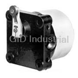
HONEYWELL GLAB26A2B

Description
Switch Limit N.O./N.C. DPDT Side Rotary with Adjustable Roller Lever Conduit Rotary Screw Mount
GLAB26A2B
Part Number
GLAB26A2B
Price
Request Quote
Manufacturer
HONEYWELL
Lead Time
Request Quote
Category
Switches » Switch Limit
Specifications
Manufacturer
Honeywell
Manufacturers Part #
GLAB26A2B
Sub-Category
Limit Switches
Brand
Micro Switch
Factory Pack Quantity
1
Datasheet


Extracted Text
MICRO SWITCH™ Global Limit Switches 002408 GLA Series Issue 1 Datasheet FEATURES • Designed to EN50041 standard, 30 mm x 60 mm mounting • Available as a standard body or plug-in body with same footprint • Wide range of actuator heads and levers • Side rotary switches factory set for CW and CCW actuation; field adjustable for CW only or CCW only • Certified for global applications; UL/CSA (Americas/Canada), CE (Europe), CCC (Asia-Pacific) • Conforms to IEC/EN 60947-5-1, EN45545-2 (GLA/GLF Series) • Sealed to IP67 and NEMA/UL 1, 4, 12, and 13 • Operating temperatures as low as -40 °C to 85 °C [-40 °F to 185 °F] • Multiple connectivity options to meet most applications: four DESCRIPTION different threaded conduits, micro-change connectors, mini- Honeywell’s MICRO SWITCH™ GLA Limit Switch Series is change connectors, Deutsch style 4-pin connector designed to global EN50041 standards and well suited for • One or two LED indicators available in switch body worldwide applications. The modular design (heads/actuators, • Single pole double throw, two pole single throw contact blocks bodies, and contact blocks) of the limit switch allows for rapid (1NC/1NO, 2NC, 2NO) are galvanically (electrically) isolated response to meet customer applications. The rugged die-cast (Zb) and designed with bifurcated contacts metal housing of the switch is ideal for indoor and outdoor • Two pole double throw contact block (2NC/2NO) has each applications where a degree of IP or NEMA enclosure sealing pole galvanically (electrically) isolated (Zb) is required. Normally closed snap-action contacts and normally • Normally closed contacts are positive opening , except closed slow-action contacts are positive opening . center neutral style • Contact blocks are available as snap action or slow action VALUE TO CUSTOMERS • Analog output available with side rotary actuator • Easy to install and maintain • Mechanical life up to 15 million operations • Rugged metal construction POTENTIAL APPLICATIONS DIFFERENTIATION • Aerial lifts, boom lifts • Side rotary actuator incorporates dual bearing design which • Automotive assembly lines and machining centers prevents side loading during operation • Agriculture equipment • Removable contact block allows for ease of wiring • Conveyors • Modular design of limit switch (heads/actuators, bodies, and • Doors and apertures contact blocks) allows for rapid customization and delivery • Material handling • Optional 1 LED or 2 LED pilot lights in limit switch front cover • Machine tools to indicate voltage present to switch and/or switch actuated • Railroad locomotives and railroad signaling equipment • Specialty contact options, sequential (2-step style) action, and • Transportation hubs center neutral action • Valves PORTFOLIO The GLA Limit Switch Series with standard or plug-in housings (EN50041 design, with 30 mm x 60 mm mounting) complement the smaller GLC Series, GLD Series and GLE Series (EN50047 design, with 20 mm to 22 mm mounting). The GLA Series is part of the MICRO SWITCH™ Limit Switch Series that includes the HDLS Series (Heavy Duty Limit Switch) and General Purpose Limit Switch (LS) Series. Sensing and Productivity Solutions MICRO SWITCH™ Global Limit Switches, GLA Series Table 1. Specifications Characteristic Parameter Description EN50041 industrial grade limit switch, standard body or plug-in body with 30 mm x 60 mm mounting Certifications CE, CCC, CSA, UL Conforming to standards IEC/EN 60947-5-1, EN45545-2 (GLA/GLF Series) Housing material Electrostatic epoxy coated zinc Side rotary, top pin plunger, top adjustable plunger, top roller plunger, top roller lever, Actuators wobble stick (multi-directional) actuator, cat whisker (multi-directional) actuator 0.5-14 NPT; PG 13,5; M20; G 1/2 (PF 1/2); Deutsch style 4-pin connector; Micro-change connector; Mini- Termination change connector; Pre-cabled Contact options* 1NC/1NO, 2NC, 2NO, 2NC/2NO, 2NC/2NO sequential, 2NC/2NO center neutral Contact type Snap action, slow action break-before-make (BBM), slow action make-before-break (MBB), slow action Contact material Silver alloy (standard), gold-plated (low-energy applications) Utilization category ac15, A300/A600; dc13, Q300 Rated operational voltage 240 Vac, 600 Vac, 250 Vdc (Ue) Rated operational current (Ie) 3 A, 1.2 A, 0.27 A Thermal current (Ith) 10 A, 2.5 A Rated insulation voltage (Ui) 300 V; 600 V Rated impulse withstand 2500 V voltage (Uimp) Short circuit protective device Class J fuse, rated 10A, 600 V (SCPD), type, and rating Pollution degree 3 Sealing IP67; NEMA/UL 1, 4, 12, and 13 -40 °C to 85 °C [-40 °C to 185 °F] side rotary actuator Operating temperature -25 °C to 85 °C [-13 °F to 185 °F] other actuators Mechanical life Up to 15 million operations Vibration (actuator not fitted) 10 g conforming to IEC 68-2-6 Shock (actuator not fitted) 50 g conforming to IEC 68-2-27 Standard limit switch with 1 LED pilot light (GLF Series) or 2 LED pilot lights (GLH Series) in front cover Options Plug-in limit switch with 1 LED pilot light (GLG Series) in front cover *Normally closed (NC) contacts are positive opening except for the center neutral limit switches Table 2. Electrical Ratings Electrical Rating ac dc A600 AC15 Q300 DC13 Gold-plated Ue Ie Ue Ie contacts (Volts) (Amps) (Volts) (Amps) 120 6 24 2.8 240 3 125 0.55 380 1.9 250 0.27 1 V 10 mA min. 50 V 100 mA max. 480 1.5 500 1.4 600 1.2 2 sensing.honeywell.com MICRO SWITCH™ Global Limit Switches, GLA Series Figure 1. Product Nomenclature GL A A 01 A E7B Body Style Heads Actuators or Levers* Switch Type (EN50041) Conduit Basic Switch GL Series 2NC/2NO, 38 mm fixed, 38 mm fixed 150 mm x 0.5-14 1NC/1NO, SPDT CW actuation 19 x 6 nylon yoke, no DPDT Side rotary Ø6,4 mm A Non plug-in A 01 20 A 1A 3 7A 1 snap action NPT only Global snap action roller rollers plastic rod 2NC/2NO, DPDT, 38 mm fixed, 38 mm fixed 141 mm x Limit 1NC/1NO, SPDT, CCW actuation Side rotary, gold contacts, gold contacts, 19 x 6 steel yoke, 19 x 6 Ø6,7 mm B Plug-in PG 13,5 07 1B 7B 2 B 22 J 3A center neutral only snap action roller nylon rollers coil spring Switch snap action Non plug-in 2NC/2NO, DPDT 38 mm fixed, 38 mm fixed 153 mm x Head with Top pin 1NC/1NO, SPDT Ø4,7 mm with 1 LED 20 mm snap action, 25 x 12 nylon yoke, 19 x 6 7C F 02 24 1C 3B C snap action** B plunger (SST) 3 lever to right pilot light LED roller steel rollers steel coil spring Top roller Plug-in 1NC/1NO, SPDT 2NC/2NO, DPDT, Adjustable 165 mm x G 1/2 38 mm fixed, Head with snap action, plunger, SST Ø1,3 mm with 1 LED snap action, gold aluminum rod, G D (PF 1/2) 12 32 C 1T 19 x 9 SST roller 4J 7D 4 lever to left 12 x 5 mm roller pilot light 1 LED** contacts, LED 200 mm max. SST wire Top roller 38 mm fixed, Adjustable Head with lever Non plug-in 1NC/1NO, 2NC/2NO, DPDT, 140 mm x with 2 LED SPDT, BBM, snap action, lever, nylon 50 x 10 rubber aluminum rod, Ø1,2 mm to mounting 03 4K H 21 D 1Y 8A 5 19 x 8 mm roller roller 140 mm max. surface pilot lights slow action sequential SST wire Top 38 to 93 mm Adjustable 190 mm x Roller plunger 1NC/1NO, SPDT, 2NC/2NO, DPDT, Ø1,2 mm BBM, slow action, snap action, gold adjustable adjustable, 19 x SST rod, perpendicular 33 28 H 2A 8B 6 4N plunger 6 nylon roller 318 mm max. SST wire to mtg. surface gold contacts contacts, sequential 2NC/2NO, DPDT, 38 to 93 mm 38 mm fixed 141 mm x 1NC/1NO, SPDT, adjustable, 19 x offset, 19 x 6 Ø6,7mm snap action, Wobble stick 2B 04 25 8C MBB, slow action E 5A LED, sequential 6 steel roller nylon roller SST coil spring 2NC/2NO, DPDT, 1NC/1NO, SPDT, 38 to 93 mm 38 mm fixed Cat snap action, gold MBB, slow action, adjustable, 38 x offset, 19 x 6 34 31 2D contacts, LED, K 5B whisker gold contacts 5 nylon roller steel roller sequential 38 to 93 mm 2NC/2NO, DPDT, 2NO, adjustable, 38 x snap action, 2W 05 slow action 26 center neutral 12 rubber roller 2NC/2NO, DPDT, 38 to 93 mm 2NO, snap action, gold adjustable, 50 x slow action, 2Y 35 29 contacts, gold contacts 10 rubber roller center neutral 2NC/2NO, DPDT, 2NC, * Levers beginning with codes 1 to 5 are for A and J style side rotary heads only. snap action, LED, Actuators beginning with Code 7 are for E style wobble stick head only. 06 slow action 27 center neutral Actuators beginning with Code 8 are for K style cat whisker head only. 2NC/2NO, DPDT, 2NC, snap action, LED, slow action, 36 30 center neutral, gold gold contacts contacts **NOTE: Basic switch codes 02 and 12 may only be used with body styles B and G. Sensing and Productivity Solutions 3 MICRO SWITCH™ Global Limit Switches, GLA Series Table 3. MICRO SWITCH™ GLA Series Side Rotary Order Guide Catalog Listing* 0.5-14 NPT 20 mm Bar Chart (degrees) Conduit Conduit ¢ contact closed £ contact open 26° 55°** 85° 21-22 > Silver 0,33 13-14 < 1NC/1NO Snap action – GLAA01A GLAC01A alloy [2.9] 12° Differential travel 26° 55°** 85° 21-22 > Silver 0,33 1 LED 13-14 < 1NC/1NO Snap action GLFA01A – alloy [2.9] (yellow) 12° Differential travel 26° 55°** 85° 21-22 > Gold- 0,33 13-14 < 1NC/1NO Snap action – GLAA07A GLAC07A plated [2.9] 12° Differential travel 26° ** 85° Slow action, Silver 0,33 21-22 1NC/1NO 13-14 – – GLAC03A BBM alloy [2.9] 38° 85° 38° ** Slow action, Silver 0,33 21-22 Side 1NC/1NO – GLAA04A – 13-14 MBB alloy [2.9] 26° rotary, no lever 26° ** 85° Silver 0,33 11-12 2NC Slow action – – GLAC06A 21-22 alloy [2.9] 26° 85° 55°** 11-12, 21-22 > Silver 0,33 13-14, 23-24 < 2NC/2NO Snap action – GLAA20A – alloy [2.9] 12° Differential travel 0° 16° † 11-12 > 2NC/2NO 13-14 < Silver 0,33 ‡ 21-22 > Center Snap action – GLAA26J – 23-24 < alloy [2.9] 8° Differential travel neutral 8° Differential travel 0° 16° † 11-12 > 2NC/2NO 13-14 < Gold- 0,33 ‡ 21-22 > Center Snap action – GLAA29J – 23-24 < plated [2.9] 8° Differential travel neutral 8° Differential travel 26° 85° 55°** Silver 0,33 21-22 > 1NC/1NO Snap action 13-14 < – GLAA01A1A GLAC01A1A alloy [2.9] 12° Differential travel 26° 55°** 85° 2 LEDs Gold- 0,33 21-22 > 1NC/1NO Snap action 13-14 < (green & GLHA07A1A – plated [2.9] 12° Differential travel yellow) 26° ** 85° 1NC/ Slow action, Silver 0,33 21-22 – GLAA03A1A – 13-14 1NO BBM alloy [2.9] 38° 26° 55°** 85° Side Silver 0,33 11-12, 21-22 > 13-14, 23-24 < 2NC/2NO Snap action – GLAA20A1A GLAC20A1A rotary, alloy [2.9] 12° Differential travel fixed lever, 26° 55°** 85° 2 LEDs 11-12, 21-22 > Silver 0,33 nylon 13-14, 23-24 < 2NC/2NO Snap action (green & – GLHC24A1A alloy [2.9] 12° Differential travel roller yellow) 42° 27° 11-12 > 2NC/2NO 13-14 < Silver 0,33 21-22 > Sequen- Snap action – GLAA21A1A – 23-24 < alloy [2.9] tial 8° Differential travel 8° Differential travel 0° 16° † 11-12 > 2NC/2NO 13-14 < Silver 0,33 ‡ 21-22 > Center Snap action – GLAA26J1A – 23-24 < alloy [2.9] 8° Differential travel neutral 8° Differential travel * Note: When conduit style G1/2 (PF1/2) is required, change the 4th digit in the catalog listing to the letter D. For example, GLAA01A1A would change to GLAD01A1A for G1/2 conduit. When conduit style PG13,5 is required, change the 4th digit in the cagalog listing to the letter B. For example, GLAA01A1A would change to GLAB01A1A for PG13,5 conduit. ** Positive opening occurs. † Contacts 11-12, 13-14 operate in CCW direction. ‡ Contacts 21-22, 23-24 operate in CW direction. 4 sensing.honeywell.com Head and Lever Type Contact Arrangement Contact Type Contact Material Operating Torque max. Nm [in-lb] With LED Pilot Light/s MICRO SWITCH™ Global Limit Switches, GLA Series Table 3. MICRO SWITCH™ GLA Series Side Rotary Order Guide, continued Catalog Listing* 0.5-14 NPT 20 mm Conduit Conduit Bar Chart (degrees) ¢ contact closed £ contact open 26° 55°** 85° 21-22 > Silver 0,33 13-14 < 1NC/1NO Snap action – GLAA01A1B GLAC01A1B alloy [2.9] 12° Differential travel 26° 55°** 85° 21-22 > Silver 0,33 1 LED 13-14 < 1NC/1NO Snap action GLFA01A1B – alloy [2.9] (yellow) 12° Differential travel 26° 55°** 85° 2 LEDs 21-22 > Silver 0,33 13-14 < 1NC/1NO Snap action (green & GLHA01A1B GLHC01A1B alloy [2.9] 12° Differential travel yellow) 26° 55°** 85° 21-22 > Gold- 0,33 13-14 < 1NC/1NO Snap action – GLAA07A1B GLAC07A1B plated [2.9] 12° Differential travel 26° ** 85° Slow action, Silver 0,33 21-22 1NC/1NO – GLAA03A1B – 13-14 BBM alloy [2.9] 38° 38° ** 85° Slow action, Silver 0,33 21-22 1NC/1NO – GLAA04A1B – 13-14 MBB alloy [2.9] 26° 26° ** 85° Silver 0,33 11-12 2NC Slow action – GLAA06A1B GLAC06A1B 21-22 alloy [2.9] 26° 55°** 85° 11-12, 21-22 > Silver 0,33 Side 13-14, 23-24 < 2NC/2NO Snap action – GLAA20A1B GLAC20A1B alloy [2.9] 12° Differential travel rotary, fixed 26° 55°** 85° Gold- 0,33 11-12, 21-22 > lever, 13-14, 23-24 < 2NC/2NO Snap action – GLAA22A1B – plated [2.9] steel 12° Differential travel roller 26° 55°** 85° Silver 0,33 11-12, 21-22 > 1 LED 13-14, 23-24 < 2NC/2NO Snap action GLFA24A1B – alloy [2.9] (yellow) 12° Differential travel 26° 85° 55°** 2 LEDs 11-12, 21-22 > Silver 0,33 13-14, 23-24 < 2NC/2NO Snap action (green & – – alloy [2.9] 12° Differential travel yellow) 26° 55°** 85° 2 LEDs 11-12, 21-22 > Gold- 0,33 13-14, 23-24 < 2NC/2NO Snap action (green & GLHA32A1B – plated [2.9] 12° Differential travel yellow) 42° 27° 11-12 > 2NC/2NO 13-14 < Silver 0,33 21-22 > Sequen- Snap action – – GLAC21A1B 23-24 < alloy [2.9] tial 8° Differential travel 8° Differential travel 0° 16° † 11-12 > 2NC/2NO 13-14 < Silver 0,33 ‡ 21-22 > Center Snap action – GLAA26J1B – 23-24 < alloy [2.9] 8° Differential travel neutral 8° Differential travel 0° 16° † 11-12 > 2NC/2NO 13-14 < Gold- 0,33 ‡ 21-22 > Center Snap action – GLAA29J1B – 23-24 < plated [2.9] 8° Differential travel neutral 8° Differential travel * Note: When conduit style G1/2 (PF1/2) is required, change the 4th digit in the catalog listing to the letter D. For example, GLAA01A1A would change to GLAD01A1A for G1/2 conduit. When conduit style PG13,5 is required, change the 4th digit in the cagalog listing to the letter B. For example, GLAA01A1A would change to GLAB01A1A for PG13,5 conduit. ** Positive opening occurs. † Contacts 11-12, 13-14 operate in CCW direction. ‡ Contacts 21-22, 23-24 operate in CW direction. Sensing and Productivity Solutions 5 Head and Lever Type Contact Arrangement Contact Type Contact Material Operating Torque max. Nm [in-lb] With LED Pilot Light/s MICRO SWITCH™ Global Limit Switches, GLA Series Table 3. MICRO SWITCH™ GLA Series Side Rotary Order Guide, continued Catalog Listing* 0.5-14 NPT 20 mm Conduit Conduit Bar Chart (degrees) ¢ contact closed £ contact open 26° 55°** 85° 21-22 > Silver 0,33 13-14 < 1NC/1NO Snap action – GLAA01A2A GLAC01A2A alloy [2.9] 12° Differential travel 26° 55°** 85° 21-22 > Gold- 0,33 13-14 < 1NC/1NO Snap action – GLAA07A2A – plated [2.9] 12° Differential travel 85° 26° ** Silver 0,33 11-12 2NC Slow action – GLAA06A2A – Side 21-22 alloy [2.9] rotary, 26° 55°** 85° adjust- Silver 0,33 11-12, 21-22 > 13-14, 23-24 < 2NC/2NO Snap action – GLAA20A2A – able alloy [2.9] 12° Differential travel lever, 26° 55°** 85° nylon Gold- 0,33 11-12, 21-22 > 13-14, 23-24 < 2NC/2NO Snap action – GLAA22A2A – roller plated [2.9] 12° Differential travel 26° 85° 55°** 11-12, 21-22 > Silver 0,33 1 LED 13-14, 23-24 < 2NC/2NO Snap action GLFA24A2A – alloy [2.9] (yellow) 12° Differential travel 0° 16° † 11-12 > 2NC/2NO 13-14 < Silver 0,33 ‡ 21-22 > Center Snap action – GLAA26J2A – 23-24 < alloy [2.9] 8° Differential travel neutral 8° Differential travel 26° 85° 55°** Silver 0,33 21-22 > 1NC/1NO Snap action 13-14 < – GLAA01A2B GLAC01A2B alloy [2.9] 12° Differential travel 26° 85° 55°** Gold- 0,33 21-22 > 1NC/1NO Snap action 13-14 < – GLAA07A2B GLAC07A2B plated [2.9] 12° Differential travel 26° 85° 55°** Silver 0,33 21-22 > 1 LED 1NC/1NO Snap action 13-14 < GLFA01A2B GLFC01A2B alloy [2.9] (yellow) 12° Differential travel 26° ** 85° Side Slow ac- Silver 0,33 21-22 1NC/1NO 13-14 – GLAA03A2B – rotary, tion, BBM alloy [2.9] 38° adjust- 26° ** 85° Slow ac- Silver 0,33 1 LED able 21-22 1NC/1NO GLFA03A2B – 13-14 tion, BBM alloy [2.9] (yellow) lever, 38° steel 26° ** 85° Slow ac- Gold- 0,33 21-22 1 LED roller 1NC/1NO 13-14 GLFA33A2B – tion, BBM plated [2.9] (yellow) 38° 26° ** 85° Silver 0,33 11-12 2NC Slow action – – GLAC06A2B 21-22 alloy [2.9] 26° 85° 55°** 11-12, 21-22 > Silver 0,33 13-14, 23-24 < 2NC/2NO Snap action – GLAA20A2B GLAC20A2B alloy [2.9] 12° Differential travel 0° 16° † 11-12 > 2NC/2NO 13-14 < Silver 0,33 ‡ 21-22 > Center Snap action – GLAA26J2B – 23-24 < alloy [2.9] neutral 8° Differential travel 8° Differential travel * Note: When conduit style G1/2 (PF1/2) is required, change the 4th digit in the catalog listing to the letter D. For example, GLAA01A1A would change to GLAD01A1A for G1/2 conduit. When conduit style PG13,5 is required, change the 4th digit in the cagalog listing to the letter B. For example, GLAA01A1A would change to GLAB01A1A for PG13,5 conduit. ** Positive opening occurs. † Contacts 11-12, 13-14 operate in CCW direction. ‡ Contacts 21-22, 23-24 operate in CW direction. 6 sensing.honeywell.com Head and Lever Type Contact Arrangement Contact Type Contact Material Operating Torque max. Nm [in-lb] With LED Pilot Light/s MICRO SWITCH™ Global Limit Switches, GLA Series Table 3. MICRO SWITCH™ GLA Series Side Rotary Order Guide, continued Catalog Listing* 0.5-14 NPT 20 mm Conduit Conduit Bar Chart (degrees) ¢ contact closed £ contact open Side rotary, adjust- 26° 85° able 55°** Silver 0,33 21-22 > lever, 1NC/1NO Snap action 13-14 < – GLAA01A2Y – alloy [2.9] 12° Differential travel Ø 50 mm rubber roller 26° 55°** 85° 21-22 > Silver 0,33 13-14 < 1NC/1NO Snap action – GLAA01A4J GLAC01A4J alloy [2.9] 12° Differential travel 26° 55°** 85° 21-22 > Silver 0,33 1 LED 13-14 < 1NC/1NO Snap action – GLFC01A4J alloy [2.9] (yellow) 12° Differential travel 26° 55°** 85° 2 LEDs 21-22 > Silver 0,33 13-14 < 1NC/1NO Snap action (green & GLHA01A4J – alloy [2.9] 12° Differential travel yellow) 26° ** 85° Slow action, Silver 0,33 21-22 1NC/1NO – GLAA03A4J – 13-14 BBM alloy [2.9] 38° 38° ** 85° Slow action, Silver 0,33 21-22 1NC/1NO – GLAA04A4J – 13-14 MBB alloy [2.9] 26° Side 26° 55°** 85° rotary, Silver 0,33 11-12, 21-22 > 2NC/2NO Snap action 13-14, 23-24 < – GLAA20A4J – adjust- alloy [2.9] 12° Differential travel able alu- 26° 55°** 85° minum Gold- 0,33 11-12, 21-22 > 13-14, 23-24 < 2NC/2NO Snap action – GLAA22A4J – rod plated [2.9] 12° Differential travel 26° 55°** 85° Silver 0,33 11-12, 21-22 > 1 LED 2NC/2NO Snap action 13-14, 23-24 < GLFA24A4J – alloy [2.9] (yellow) 12° Differential travel 26° 55°** 85° 11-12, 21-22 > Gold- 0,33 1 LED 13-14, 23-24 < 2NC/2NO Snap action – GLFC32A4J plated [2.9] (yellow) 12° Differential travel 26° 55°** 85° 2 LEDs Silver 0,33 11-12, 21-22 > 2NC/2NO Snap action 13-14, 23-24 < (green & GLHA24A4J – alloy [2.9] 12° Differential travel yellow) 42° 27° 11-12 > 13-14 < 2NC/2NO Silver 0,33 21-22 > Snap action – GLAA21A4J – 23-24 < Sequential alloy [2.9] 8° Differential travel 8° Differential travel * Note: When conduit style G1/2 (PF1/2) is required, change the 4th digit in the catalog listing to the letter D. For example, GLAA01A1A would change to GLAD01A1A for G1/2 conduit. When conduit style PG13,5 is required, change the 4th digit in the cagalog listing to the letter B. For example, GLAA01A1A would change to GLAB01A1A for PG13,5 conduit. ** Positive opening occurs. Sensing and Productivity Solutions 7 Head and Lever Type Contact Arrangement Contact Type Contact Material Operating T orque max. Nm [in-lb] With LED Pilot Light/s MICRO SWITCH™ Global Limit Switches, GLA Series Table 3. MICRO SWITCH™ GLA Series Side Rotary Order Guide, continued Catalog Listing* 0.5-14 NPT 20 mm Conduit Conduit Bar Chart (degrees) ¢ contact closed £ contact open 85° 26° ** Silver 0,33 Side 11-12 2NC Slow action – GLAA06A5A – 21-22 alloy [2.9] rotary, fixed off- set lever, 26° 55°** 85° nylon Silver 0,33 11-12, 21-22 > 13-14, 23-24 < 2NC/2NO Snap action – GLAA20A5A – roller alloy [2.9] 12° Differential travel * Note: When conduit style G1/2 (PF1/2) is required, change the 4th digit in the catalog listing to the letter D. For example, GLAA01A1A would change to GLAD01A1A for G1/2 conduit. When conduit style PG13,5 is required, change the 4th digit in the cagalog listing to the letter B. For example, GLAA01A1A would change to GLAB01A1A for PG13,5 conduit. ** Positive opening occurs. Table 4. MICRO SWITCH™ GLA Series Plunger Order Guide Catalog Listing* 0.5-14 NPT 20 mm Conduit Conduit Bar Chart (millimeters) ¢ contact closed £ contact open 37.5 35 30.5 33** Silver 16 21-22 > 13-14 < 1NC/1NO Snap action – GLAA01B GLAC01B alloy [3.6] 0.9 Differential travel 37.5 35 30.5 33** Silver 16 21-22 > 1 LED 13-14 < 1NC/1NO Snap action GLFA01B GLFC01B alloy [3.6] (yellow) 0.9 Differential travel 37.5 35 30.5 33** Gold- 16 21-22 > 1NC/1NO Snap action 13-14 < – – GLAC07B plated [3.6] 0.9 Differential travel 37.5 35** 30.5 Slow action, Silver 16 21-22 > 1NC/1NO 13-14 < – GLAA03B – BBM alloy [3.6] 34 Top pin 37.5 35 33** 30.5 11-12, 21-22 > Silver 16 plunger 13-14, 23-24 < 2NC/2NO Snap action – GLAA20B GLAC20B alloy [3.6] 0.9 Differential travel 37.5 35 33** 30.5 11-12, 21-22 > Silver 16 1 LED 13-14, 23-24 < 2NC/2NO Snap action GLFA24B – alloy [3.6] (yellow) 0.9 Differential travel 37.5 35 33** 30.5 11-12, 21-22 > Gold- 16 13-14, 23-24 < 2NC/2NO Snap action – GLAA22B GLAC22B plated [3.6] 0.9 Differential travel 33.8 37.5 35 30.5 11-12 > 13-14 < Gold- 16 1 LED 21-22 > 2NC/2NO Snap action GLFA32B – 23-24 < plated [3.6] (yellow) 0.8 Differential travel 0.8 Differential travel * Note: When conduit style G1/2 (PF1/2) is required, change the 4th digit in the catalog listing to the letter D. For example, GLAA01A1A would change to GLAD01A1A for G1/2 conduit. When conduit style PG13,5 is required, change the 4th digit in the cagalog listing to the letter B. For example, GLAA01A1A would change to GLAB01A1A for PG13,5 conduit. ** Positive opening occurs. 8 sensing.honeywell.com Head Type Head and Lever Type Contact Arrangement Contact Arrangement Contact Type Contact Type Contact Material Contact Material Operating Force max. Operating T orque max. N [lb] Nm [in-lb] With LED Pilot Light/s With LED Pilot Light/s MICRO SWITCH™ Global Limit Switches, GLA Series Table 5. MICRO SWITCH™ GLA Series Roller Plunger Order Guide Catalog Listing* 0.5-14 NPT 20 mm Conduit Conduit Bar Chart (millimeters) ¢ contact closed £ contact open 50.5 48 43.5 46** 21-22 > Silver 16 13-14 < 1NC/1NO Snap action – GLAA01C GLAC01C alloy [3.6] 0.9 Differential travel 50.5 48 43.5 46** 21-22 > Silver 16 1 LED 13-14 < 1NC/1NO Snap action GLFA01C – alloy [3.6] (yellow) 0.9 Differential travel 50.5 48 46** 43.5 2 LEDs 21-22 > Silver 16 13-14 < 1NC/1NO Snap action (green & GLHA01C – alloy [3.6] 0.9 Differential travel yellow) 50.5 48 46** 43.5 21-22 > Gold- 16 13-14 < 1NC/1NO Snap action – GLAA07C GLAC07C plated [3.6] 0.9 Differential travel 50.5 48 46** 43.5 21-22 > Gold- 16 1 LED 13-14 < 1NC/1NO Snap action GLFA07C – plated [3.6] (yellow) 0.9 Differential travel 50.5 48** 43.5 Slow action, Silver 16 21-22 > 1NC/1NO – GLAA03B – 13-14 < BBM alloy [3.6] 47 50.5 47** 43.5 Slow action, Silver 16 21-22 > Top 1NC/1NO 13-14 – GLAA04B – < MBB alloy [3.6] 48 roller plunger 50.5 48** 43.5 Silver 16 11-12 > 2NC Slow action – GLAA06C GLAC06C 21-22 < alloy [3.6] 50.5 48 46** 43.5 11-12, 21-22 > Silver 16 13-14, 23-24 < 2NC/2NO Snap action – GLAA20C GLAC20C alloy [3.6] 0.9 Differential travel 50.5 48 46** 43.5 11-12, 21-22 > Gold- 16 13-14, 23-24 < 2NC/2NO Snap action – GLAA22C – plated [3.6] 0.9 Differential travel 50.5 48 46** 43.5 11-12, 21-22 > Silver 16 1 LED 13-14, 23-24 < 2NC/2NO Snap action GLFA24C – alloy [3.6] (yellow) 0.9 Differential travel 50.5 48 46** 43.5 2 LEDs 11-12, 21-22 > Gold- 16 13-14, 23-24 < 2NC/2NO Snap action (green & – GLHC32C plated [3.6] 0.9 Differential travel yellow) 45.8 50.5 48 43.5 11-12 > 13-14 < 2NC/2NO Silver 16 21-22 > Snap action – GLAA21C – 23-24 < Sequential alloy [3.6] 0.8 Differential travel 0.8 Differential travel * Note: When conduit style G1/2 (PF1/2) is required, change the 4th digit in the catalog listing to the letter D. For example, GLAA01A1A would change to GLAD01A1A for G1/2 conduit. When conduit style PG13,5 is required, change the 4th digit in the cagalog listing to the letter B. For example, GLAA01A1A would change to GLAB01A1A for PG13,5 conduit.. ** Positive opening occurs. Sensing and Productivity Solutions 9 Head Type Contact Arrangement Contact Type Contact Material Operating Force max. N [lb] With LED Pilot Light/s MICRO SWITCH™ Global Limit Switches, GLA Series Table 6. MICRO SWITCH™ GLA Series Wobble Order Guide Catalog Listing* 0.5-14 NPT 20 mm Conduit Conduit Bar Chart (degrees) ¢ contact closed £ contact open Wobble 18° 35° stick, 21-22 > Silver 0,2 13-14 < 150 mm 1NC/1NO Snap action – GLAA01E7A – alloy [1.8] 8° Differential travel plastic rod 18° 35° 21-22 > Silver 0,2 13-14 < 1NC/1NO Snap action – GLAA01E7B GLAC01E7B alloy [1.8] 8° Differential travel 18° 35° 21-22 > Silver 0,2 1 LED 13-14 < 1NC/1NO Snap action GLFA01E7B GLFC01E7B alloy [1.8] (yellow) 8° Differential travel 18° 35° 2 LEDs 21-22 > Silver 0,2 13-14 < 1NC/1NO Snap action (green & GLHA01E7B – alloy [1.8] 8° Differential travel Wobble yellow) stick, 18° 35° 21-22 > Gold- 0,2 141 mm 13-14 < 1NC/1NO Snap action – – GLAC07E7B plated [1.8] sst coil 8° Differential travel spring 18° 35° Slow action, Silver 0,2 21-22 > 1NC/1NO – – – 13-14 < BBM alloy [1.8] 25° 18° 35° Silver 0,2 11-12, 21-22 > 13-14, 23-24 < 2NC/2NO Snap action – GLAA20E7B GLAC20E7B alloy [1.8] 8° Differential travel 18° 35° 11-12, 21-22 > Silver 0,2 1 LED 13-14, 23-24 < 2NC/2NO Snap action GLFA24E7B – alloy [1.8] (yellow) 8° Differential travel Wobble 18° 35° 21-22 > stick, Silver 0,2 13-14 < 1NC/1NO Snap action – GLAA01E7D – 165 mm alloy [1.8] 8° Differential travel sst wire * Note: When conduit style G1/2 (PF1/2) is required, change the 4th digit in the catalog listing to the letter D. For example, GLAA01A1A would change to GLAD01A1A for G1/2 conduit. When conduit style PG13,5 is required, change the 4th digit in the cagalog listing to the letter B. For example, GLAA01A1A would change to GLAB01A1A for PG13,5 conduit. 10 sensing.honeywell.com Head Type Contact Arrangement Contact Type Contact Material Operating Force max. N [lb] With LED Pilot Light/s MICRO SWITCH™ Global Limit Switches, GLA Series Table 6. MICRO SWITCH™ GLA Series Wobble Order Guide, continued Catalog Listing* 0.5-14 NPT 20 mm Conduit Conduit Bar Chart (degrees) ¢ contact closed £ contact open Cat 18° 21-22 > whisker, Silver 0,1 13-14 < 1NC/1NO Snap action – GLAA01K8A – 140 mm alloy [0.9] 8° Differential travel sst wire 18° Silver 0,1 21-22 > 13-14 < 1NC/1NO Snap action – GLAA01K8B – alloy [0.9] 8° Differential travel Cat whisker, 190 mm sst wire 18° Silver 0,1 11-12, 21-22 > 13-14, 23-24 < – 2NC/2NO Snap action GLAA20K8B GLAC20K8B alloy [0.9] 8° Differential travel 18° Silver 0,1 21-22 > 13-14 < 1NC/1NO Snap action – GLAA01K8C – alloy [0.9] 8° Differential travel Cat whisker, 141 mm sst coil spring 18° 11-12, 21-22 > Silver 0,1 13-14, 23-24 < 2NC/2NO Snap action – GLAA20K8C – alloy [0.9] 8° Differential travel * Note: When conduit style G1/2 (PF1/2) is required, change the 4th digit in the catalog listing to the letter D. For example, GLAA01A1A would change to GLAD01A1A for G1/2 conduit. When conduit style PG13,5 is required, change the 4th digit in the cagalog listing to the letter B. For example, GLAA01A1A would change to GLAB01A1A for PG13,5 conduit. Sensing and Productivity Solutions 11 Head Type Contact Arrangement Contact Type Contact Material Operating Force max. N [lb] With LED Pilot Light/s MICRO SWITCH™ Global Limit Switches, GLA Series Table 7. MICRO SWITCH™ GLA Series Top Roller Lever Order Guide Catalog Listing* 0.5-14 NPT 20 mm Conduit Conduit Bar Chart (millimeters) ¢ contact closed £ contact open 65,2 61 56,9** 52 Silver 9,5 21-22 > 1NC/1NO Snap action 13-14 < – GLAA01D GLAC01D alloy [2.1] 1,7 Differential travel 65,2 61 56,9** 52 21-22 > Silver 9,5 1 LED 13-14 < 1NC/1NO Snap action GLFA01D – alloy [2.1] (yellow) 1,7 Differential travel Top 65,2 59,1** 52 Slow action, Silver 9,5 21-22 > roller 1NC/1NO – GLAA04D – 13-14 < MBB alloy [2.1] 61 lever 65,2 61 56,9** 52 > Silver 9,5 11-12, 21-22 13-14, 23-24 < 2NC/2NO Snap action – GLAA20D GLAC20D alloy [2.1] 1,7 Differential travel 65,2 61 56,9** 52 Gold- 9,5 11-12, 21-22 > 2NC/2NO Snap action 13-14, 23-24 < – GLAA22D GLAC22D plated [2.1] 1,7 Differential travel * Note: When conduit style G1/2 (PF1/2) is required, change the 4th digit in the catalog listing to the letter D. For example, GLAA01A1A would change to GLAD01A1A for G1/2 conduit. When conduit style PG13,5 is required, change the 4th digit in the cagalog listing to the letter B. For example, GLAA01A1A would change to GLAB01A1A for PG13,5 conduit. ** Positive opening occurs. 12 sensing.honeywell.com Head Type Contact Arrangement Contact Type Contact Material Operating Force max. N [lb] With LED Pilot Light/s MICRO SWITCH™ Global Limit Switches, GLA Series Table 8. MICRO SWITCH™ GLB Series Side Rotary Order Guide (Plug-in Body) Catalog Listing* 0.5-14 NPT 20 mm Conduit Conduit Bar Chart (degrees) ¢ contact closed £ contact open 26° 85° 55°** Side 21-22 > Silver 0,33 13-14 < rotary, 1NC/1NO Snap action – GLBA02A GLBC02A alloy [2.9] 12° Differential travel no lever Side rotary, 26° 55°** 85° 21-22 > fixed Silver 0,33 1NC/1NO Snap action 13-14 < – GLBA02A1A – alloy [2.9] lever, 12° Differential travel nylon roller 26° 55°** 85° Side 21-22 > Silver 0,33 13-14 < – 1NC/1NO Snap action GLBA02A1B GLBC02A1B rotary, alloy [2.9] 12° Differential travel fixed lever, 26° 55°** 85° 21-22 > Silver 0,33 1 LED steel 13-14 < 1NC/1NO Snap action GLGA12A1B GLGC12A1B alloy [2.9] (yellow) 12° Differential travel roller Side rotary, 26° 55°** 85° adjust- 21-22 > Silver 0,33 13-14 < – able 1NC/1NO Snap action GLBA02A2A GLBC02A2A alloy [2.9] 12° Differential travel lever, nylon roller Side 26° 55°** 85° 21-22 > Silver 0,33 rotary, 13-14 < 1NC/1NO Snap action – GLBA02A2B GLBC02A2B alloy [2.9] 12° Differential travel adjust- able 26° 55°** 85° lever, 21-22 > Silver 0,33 1 LED 1NC/1NO Snap action 13-14 < GLGA12A2B – steel alloy [2.9] (yellow) 12° Differential travel roller 26° 55°** 85° 21-22 > Side Silver 0,33 1NC/1NO Snap action 13-14 < – GLBA02A4J GLBC02A4J alloy [2.9] rotary, 12° Differential travel adjust- able 26° 55°** 85° 21-22 > Silver 0,33 1 LED alumi- 1NC/1NO Snap action 13-14 < GLGA12A4J – (yellow) alloy [2.9] num rod 12° Differential travel * Note: When conduit style G1/2 (PF1/2) is required, change the 4th digit in the catalog listing to the letter D. For example, GLAA01A1A would change to GLAD01A1A for G1/2 conduit. When conduit style PG13,5 is required, change the 4th digit in the cagalog listing to the letter B. For example, GLAA01A1A would change to GLAB01A1A for PG13,5 conduit. ** Positive opening occurs. Sensing and Productivity Solutions 13 Head Type Contact Arrangement Contact Type Contact Material Operating Torque max. Nm [in-lb] With LED Pilot Light/s MICRO SWITCH™ Global Limit Switches, GLA Series Table 9. MICRO SWITCH™ GLB Series Top Plunger Order Guide (Plug-in Body) Catalog Listing* 0.5-14 NPT 20 mm Conduit Conduit Bar Chart (millimeters) ¢ contact closed £ contact open 37.5 35 30.5 33** Silver 16 21-22 > 13-14 < 1NC/1NO Snap action – GLBA02B GLBC02B alloy [3.6] 0.9 Differential travel Top pin 37.5 35 30.5 plunger 33** Silver 16 21-22 > 1 LED 13-14 < 1NC/1NO Snap action GLGA12B GLGC12B alloy [3.6] (yellow) 0.9 Differential travel 37.5 35 33** 30.5 21-22 > Silver 16 13-14 < 1NC/1NO Snap action – GLBA02C GLBC02C Top alloy [3.6] 0.9 Differential travel roller 37.5 35 30.5 33** plunger Silver 16 21-22 > 1 LED 13-14 < 1NC/1NO Snap action GLGA12C – alloy [3.6] (yellow) 0.9 Differential travel Table 10. MICRO SWITCH™ GLB Series Top Roller Lever Order Guide (Plug-in Body) Catalog Listing* 0.5-14 NPT 20 mm Conduit Conduit Bar Chart (millimeters) ¢ contact closed £ contact open 65,2 61 56,9** 52 Silver 9.5 11-12, 21-22 > 13-14, 23-24 < 1NC/1NO Snap action – GLBA02D GLBC02D alloy [2.1] 1,7 Differential travel Top roller lever 65,2 61 56,9** 52 Silver 9.5 11-12, 21-22 > 1 LED 13-14, 23-24 < 1NC/1NO Snap action GLGA12D – (yellow) alloy [2.1] 1,7 Differential travel * Note: When conduit style G1/2 (PF1/2) is required, change the 4th digit in the catalog listing to the letter D. For example, GLAA01A1A would change to GLAD01A1A for G1/2 conduit. When conduit style PG13,5 is required, change the 4th digit in the cagalog listing to the letter B. For example, GLAA01A1A would change to GLAB01A1A for PG13,5 conduit. ** Positive opening occurs. 14 sensing.honeywell.com Head Type Head Type Contact Arrangement Contact Arrangement Contact Type Contact Type Contact Mtl Contact Mtl Operating Force max. Operating Force max. N [lb] N [lb] With LED Pilot Light With LED Pilot Light/s MICRO SWITCH™ Global Limit Switches, GLA Series Table 11. MICRO SWITCH™ GLB Series Wobble Order Guide (Plug-in Body) Catalog Listing* 0.5-14 NPT 20 mm Conduit Conduit Bar Chart (degrees) ¢ contact closed £ contact open Wobble 18° 35° stick, 21-22 > Silver 0,1 13-14 < 150 mm 1NC/1NO Snap action – GLBA02E7A – alloy [0.9] 8° Differential travel plastic rod 18° 35° 21-22 > Silver 0,1 Wobble 13-14 < 1NC/1NO Snap action – GLBA02E7B GLBC02E7B alloy [0.9] stick, 8° Differential travel 141 18° 35° mm coil 21-22 > 1 LED Silver 0,1 13-14 < 1NC/1NO Snap action GLGA12E7B – spring (yellow) alloy [0.9] 8° Differential travel Cat 18° 35° Whisker, Silver 0,1 21-22 > 13-14 < 1NC/1NO Snap action – GLBA02K8B – 190 mm alloy [0.9] 8° Differential travel sst wire Cat 18° 35° whisker, 21-22 > Silver 0,1 13-14 < 141 mm 1NC/1NO Snap action – GLBA02K8C – alloy [0.9] 8° Differential travel sst coil spring * Note: When conduit style G1/2 (PF1/2) is required, change the 4th digit in the catalog listing to the letter D. For example, GLAA01A1A would change to GLAD01A1A for G1/2 conduit. When conduit style PG13,5 is required, change the 4th digit in the cagalog listing to the letter B. For example, GLAA01A1A would change to GLAB01A1A for PG13,5 conduit.. Sensing and Productivity Solutions 15 Head Type Contact Arrangement Contact Type Contact Mtl Operating Force max. N [lb] With LED Pilot Light/s MICRO SWITCH™ Global Limit Switches, GLA Series Product Dimensions: GLA Series Figure 2. Fixed Lever, Side Rotary Switch - Non-plug-in Body Style, GLZ51 Style Lever, and GLA Body Y Ø X Z 70,00 MAX 38,1 mm 2,756 1.50 in 20,0 mm 0.79 in ROLLER LEVER X DIM Y DIM Z DIM (catalog listing) MATL 55,9 6,4 19,1 GLZ51A NYLON 2.20 .25 .75 55,9 6,4 19,1 GLZ51B STEEL 2.20 .25 .75 102,9 mm 62,0 mm 59,1 12,7 24,5 4.05 in GLZ51C NYLON 2.44 in 2.33 .50 60,0 mm 1.00 82,0 mm 2.36 in 66,1 10,0 50,0 3.23 in GLZ51Y RUBBER 2.60 .39 1.97 75,8 mm 56.8 8.8 19.1 2.99 in STAINLESS GLZ51T 2.24 .345 7,3 mm STEEL .75 0.29 in CONDUIT ENTRY Ø 5,3 mm Ø 0.21 in 5,3 mm 0.21 in 16,0 mm 30,0 mm 0.63 in 31,5 mm 1.18 in 1.24 in 42,0 mm 42,0 mm 1.65 in 1.65 in Figure 3. Fixed Lever, Side Rotary Switch - Plug-in Body Style, GLZ51 Style Lever, and GLB Body 6,4 mm [0.25 in] 55,9 mm [2.20 in] 50,0 mm [1.97 in] Ø 19,1 mm [Ø 0.75 in] 38,1 mm 70,00 mm max. [1.50 in] [2,756 in max.] 20,0 mm [0.79 in] 102,9 mm [4.05 in] 60,0 mm 69,7 mm [2.36 in] [2.74 in] 62,0 mm 75,8 mm [2.44 in] [2.99 in] 7,3 mm [0.29 in] CONDUIT ENTRY Ø 5,3 mm [Ø 0.21 in] 5,3 16,0 mm [0.63 in] 31,5 mm 30,0 mm [1.24 in] [1.18 in] 42,0 mm 41,5 mm [1.65 in] [1.63 in] 16 sensing.honeywell.com MICRO SWITCH™ Global Limit Switches, GLA Series Figure 4. Adjustable Lever Dimensions, GLZ52 Y Z Ø X LEVER ROLLER X DIM Y DIM Z DIM MATL 19,1 65,9 6,4 38,1 mm to 91,5 mm adjustment GLZ52A NYLON .75 2.59 .25 1.50 in to 3.60 in adjustment 19,1 65,9 6,4 GLZ52B STEEL .75 2.59 .25 38,1 65,9 6,4 GLZ52D NYLON 1.5 2.59 .25 19,1 79,37 33,07 GLZ52E NYLON .75 3.125 1.300 40,0 71,5 12,7 GLZ52W RUBBER 1.6 2.81 .5 50,0 68,8 10,0 GLZ52Y RUBBER 1.97 2.71 .39 Figure 5. Aluminum Rod Lever Dimensions, GLZ54 6,5 mm [0.26 in] Ø 3,2 mm [Ø 0.13 in] GLZ54J: 200,0 mm [7.87 in] GLZ54K: 140,0 mm [5.51] Aluminum Rod GLZ54J: 201,5 mm [7.93 in] GLZ54K: 141,0 mm [5.56] 59,2 mm [2.33 in] Sensing and Productivity Solutions 17 MICRO SWITCH™ Global Limit Switches, GLA Series Figure 6. Pin Plunger Dimensions Figure 7. Roller Plunger Dimensions 16,0 16,0 Ø 10,0 4,7 [0.63] [0.63] [Ø 0.39] [0.19] Steel roller Ø 12,4 37,5 [Ø 0.49] [1.48] 50,5 [1.99] Top Pin Plunger Refer to Figure 2 or 3 for other dimensions Top Roller Plunger Refer to Figure 2 or 3 for other dimensions Figure 8. Roller Lever Dimensions 16,0 7,9 [0.63] [0.31] 13,0 [0.51] 14,0 [0.55] 65,2 Ø 18,7 [2.57] [Ø 0.74] 35,0 [1.38] Top Roller Lever Refer to Figure 2 or 3 for other dimensions 18 sensing.honeywell.com MICRO SWITCH™ Global Limit Switches, GLA Series Head Code: E • WOBBLE AND CAT WHISKER ACTUATOR DIMENSIONS Figure 10. Plastic Rod and Flexible Cable Figure 9. Coil Actuator Ø6,4 mm 16,0 mm Plastic tip [Ø0.25 in] [0.63 in] Cable Plastic 141,1 mm [5.55 in] 153,5 mm 150,3 mm [6.04 in] [5.92 in] Refer to Figure 2 or 3 for other dimensions Refer to Figure 2 or 3 for other dimensions Figure 11. Cat Whisker Wobbles 5.5 inches (stainless steel) 6.5 inches (stainless steel) 7.5 inches (stainless steel) Ø1,2 mm [Ø0.05 in] Ø1,3 mm [Ø0.05 in] Ø1,2 mm [Ø0.05 in] 190,5 mm [7.5 in] 165,1 mm [6.50 in] 139,7 mm [5.50 in] Refer to Figure 2 or 3 for other dimensions Sensing and Productivity Solutions 19 MICRO SWITCH™ Global Limit Switches, GLA Series Figure 14. Actuation Adjustment APPLICATION INFORMATION Side Rotary Assemblies The side rotary assemblies incorporate a feature for adjusting the free position of the side rotary lever. The EN 50041 body style allows infinite adjustment and reclamp. See the following dia- grams for details of the mechanism in each case. Figure 12. Standard EN 50041 Body Style REPLACEMENT INSTRUCTIONS All levers for side rotary assemblies are available as replacment parts. All basics, except the plug-in, can be replaced. All EN 50041 heads can be replaced. The replacement procedures for these components are straightforward in nature. Side Rotary Levers Remove the lever from the product being replaced. On EN 50041 product this is achieved by loosening the Allen screw holding the There are two lever mounting options: lever on the shaft. Replace the lever and tighten the Allen screw 1. By fully seating the lever in one of the four 90° detent posi- or combination screw. Re-test the switch in its application. tions on the shaft hub which provides positive lever retention. 2. By mounting the lever on the serrated portion of the shaft Heads (which enables the lever to be mounted in any position). All EN 50041 style switch heads can be removed and replaced. 1. Remove the head by unscrewing the four retaining screws on To change the rotary lever’s free position: the head assembly. 1. Use a 3 mm hex Allen wrench to loosen the Allen screw, as 2. Ensure replacement part is identical to one being removed. shown in Figure 13, below. 3. Re-test the assembly and ensure correct operation. 2. Back off the lever 2 mm and move it to the desired free position. Basic Switches 3. Retighten the Allen screw. Non-plug-in 4. Check to see if the free position is satisfactory for the Basic switches can be removed and replaced by following this application. procedure: 5. Repeat the adjustment procedure if necessary. 1. Remove the cover from the body. 2. Before disconnecting the switch wiring, carefully note the A teller tab located at the bottom of the lever (see diagram below) wiring arrangement for your application, particularly the safety helps prevent lever slippage. It enables the installer to detect the ground connection. correct tightening torque. When this tab cannot be moved, the 3. Remove the basic switch retaining screw. Allen screw has been tightened properly. 4. Remove the basic switch and install the replacement basic Figure 13. Allen Screw and Teller Tab Location switch. 5. Use the retaining screw to install the new basic switch – ensure that it is correctly seated in the switch body. 6. Wire the switch terminals as before. 7. Before replacing the cover – ensure that the basic switch wires are not twisted or otherwise lifted from the basic switch (to prevent them from becoming trapped when the cover is EN 50041 Side Rotary Actuator Direction Adjustment replaced). As furnished, GLS rotary switches will operate when the lever is 8. Test the switch in its application. rotated from either the left or right. They can be field modified to operate in one direction only (Clockwise CW; Counter clockwise Figure 15. Retaining screw location CCW) by following these steps: 1. Carefully remove the complete head assembly. 2. Turn the head assembly upside down as shown in Figure 14. 3. Pull the plunger mechanism out and rotate it through 90° increments until the alignment tab points to the desired func- tion (CW, CCW, or CW and CCW). 4. Push plunger mechanism in. 5. Reassemble the head assembly and re-test the switch in its application. 20 sensing.honeywell.com MICRO SWITCH™ Global Limit Switches, GLA Series Basic Switches Figure 17. Wiring Diagram 2 Plug-in EN50041 body style The switch enclosure portion of this two-piece body style plugs into a pre-wired terminal block mounted in the application. Replacement is accomplished by unplugging the old switch enclosure and plugging-in a new switch enclosure (basics are permanently staked in the switch enclosure). LED WIRING The GLF, GLG, and GLH versions of GLS (EN 50041) come In Figure 17, Wiring Diagram 2, the basic switch contact is complete with LED indicators. These indicators can be wired in a closed. The current for the LED cannot flow through the LED and variety of ways. Operation can indicate switch free or switch the LED will not illuminate. operated depending on the wiring arrangement employed. The table below indicates the body styles and indicators offered. Figure 18. Wiring Diagram 3 Table 12. LED Series Body Function Specification GLF 1 LED 12 Æ 250 Vac and dc less than 1.5 mA draw GLG 1 LED plug-in 12 Æ 250 Vac and dc less than 1.5 mA draw GLH 2 LED 18 Æ 30 Vdc 7 mA typ. current draw The following wiring diagrams show possible configurations that can be used for the LEDs. Combinations of these arrange- ments can be used where the dual LED versions of GLS are employed. In Figure 18, Wiring Diagram 3, regardless of the position of the Figure 16. Wiring Diagram 1 basic switch, the current for the LED can flow through the LED and the LED will illuminate indicating power available. Figure 19. Wiring Diagram 4 In Figure 16, Wiring Diagram 1, the basic switch contact is open. The current for the LED can flow through the LED (via the load) and the LED illuminates. In Figure 19, Wiring Diagram 4, when the load is energized the LED will illuminate. The above examples suggest options with these versions of GLS. The LED pilot lights should be treated as ’’for indication only’’ devices. Note: While every effort is made to ensure that the above guidelines are accurate, no responsibility can be accepted for failure to apply good engineering practice to machinery design and use of Honeywell products. Never apply any of the procedures outlined above on live circuits. Ensure that testing of changes is carried out with no risk of injury during tests. These guidelines are produced to help our customers make the right choices in applying our Limit Switches to general applications. Contact your local Honeywell representative if you have any difficulties. Sensing and Productivity Solutions 21 MICRO SWITCH™ Global Limit Switches, GLA Series REPLACEMENT PARTS - Levers REPLACEMENT PARTS - Basic Switches Rod/ Rod/ Roller GLF GLH Catalog GLA Roller Roller Dia. Width mm Basic Switch Code Body Body Listing Body Material mm [in] [in] (1 LED) (2 LEDs) Fixed length lever; 38,1 mm [1.5 in] radius 01; 1NC/1NO, snap action GLZ301 GLZ301 GLZ301 GLZ51A Nylon 19,0 [0.75] 6,35 [0.25] 03; 1NC/1NO, slow action GLZ303 GLZ303 GLZ303 BBM GLZ51B Steel 19,0 [0.75] 6,35 [0.25] 04; 1NC/1NO, slow action GLZ51C Nylon 25,4 [1.00] 12,7 [0.50] GLZ304 GLZ304 GLZ304 MBB GLZ51E Bronze 19,0 [0.75] 6,35 [0.25] 06; 2NC, Slow action GLZ306 GLZ306 GLZ306 GLZ51T SST 19,0 [0.75] 9,5 [0.38] 07; 1NC/1NO, snap action, GLZ307 GLZ307 GLZ307 GLZ51Y Rubber 50,0 [1.97] 10,0 [0.39] gold contacts Adjustable length lever; 38,1 to 89,0 mm [1.5 to 3.5 in] radius 20; 2NC/2NO, snap action GLZ320 – – GLZ52A Nylon 19,0 [0.75] 6,35 [0.25] 21; 2NC/2NO, snap action, GLZ321 – – sequence GLZ52B Steel 19,0 [0.75] 6,35 [0.25] 22; 2NC/2NO, snap action, GLZ322 – – GLZ52D Nylon 38,1 [1.50] 6,35 [0.25] gold contacts GLZ52E Nylon 19,0 [0.75] 33,1 [1.30] 24; 2NC/2NO, snap action, use – GLZ324 GLZ324 with LED body GLZ52W Rubber 40.7 [1.60] 12,7 [0.50] 26; 2NC/2NO, snap action, GLZ326 – – GLZ52Y Rubber 50,0 [1.97] 10,0 [0.39] center neutral Fixed length yoke lever; 38,1 mm [1.5in] radius 32; 2NC/2NO, snap action, GLZ53 No rollers n/a n/a gold-plated contacts, use with – GLZ332 GLZ332 LED body GLZ53A Nylon 19,0 [0.75] 6,35 [0.25] 33; 1NC/1NO, slow action GLZ53B Steel 19,0 [0.75] 6,35 [0.25] GLZ333 GLZ333 GLZ333 BBM, gold-plated contacts GLZ53E Bronze 19,0 [0.75] 6,35 [0.25] 34; 1NC/1NO, slow action, GLZ334 GLZ334 GLZ334 Adjustable rod levers MBB, gold plated contacts 36; 2NC, slow action, gold- GLZ336 GLZ336 GLZ336 GLZ54 Hub only n/a n/a plated contacts Alum. rod 3,17 mm GLZ54J 200 mm n/a [0.125 in] [7.9 in] Alum. rod 3,17 mm GLZ54K 140 mm n/a [0.125 in] [5.51 in] SST rod 3,17 mm GLZ54N 318 mm n/a [0.125 in] [12.5 in] Fixed length offset lever; 38,1 mm [1.5 in] radius GLZ55A Nylon 19,0 [0.75] 6,35 [0.25] GLZ55B Steel 19,0 [0.75] 6,35 [0.25] GLZ55E Bronze 19,0 [0.75] 6,35 [0.25] Fixed length spring rod Delrin rod, GLZ68 305 mm 6,35 [0.25] n/a [12.0 in] 22 sensing.honeywell.com MICRO SWITCH™ Global Limit Switches, GLA Series REPLACEMENT PARTS - Heads Head type GLA GLB GLF GLG GLH A; Side rotary, less lever GLZ1AA GLZ1AA GLZ1AA GLZ1AA GLZ1AA B; Top pin plunger GLZ1AB GLZ1AB GLZ1AB GLZ1AB GLZ1AB C; Top roller plunger GLZ1AC GLZ1AC GLZ1AC GLZ1AC GLZ1AC D; Top roller lever GLZ1AD GLZ1AD GLZ1AD GLZ1AD GLZ1AD E7A; Wobble plastic rod, 150 mm GLZ1AE7A GLZ1AE7A GLZ1AE7A GLZ1AE7A GLZ1AE7A E7B; Wobble sst coil spring, 141 mm GLZ1AE7B GLZ1AE7B GLZ1AE7B GLZ1AE7B GLZ1AE7B E7D; Wobble sst wire, 165 mm GLZ1AE7D GLZ1AE7D GLZ1AE7D GLZ1AE7D GLZ1AE7D K8A; Cat whisker, 140 mm sst wire GLZ1AK8A GLZ1AK8A GLZ1AK8A GLZ1AK8A GLZ1AK8A K8B; Cat whisker, 190 mm sst wire GLZ1AK8B GLZ1AK8B GLZ1AK8B GLZ1AK8B GLZ1AK8B K8C; Cat whisker, sst coil spring GLZ1AK8C GLZ1AK8C GLZ1AK8C GLZ1AK8C GLZ1AK8C Sensing and Productivity Solutions 23 m WARNING ADDITIONAL MATERIALS PERSONAL INJURY The following associated literature is available at DO NOT USE these products as safety or emergency stop sensing.honeywell.com: devices or in any other application where failure of the product • Product range guide could result in personal injury. • Product application-specific information Failure to comply with these instructions could result in death or serious injury. – Sensors and switches in front loaders – Sensors and switches in mobile cranes – Sensors and switches in oil rig applications m WARNING MISUSE OF DOCUMENTATION • The information presented in this product sheet is for reference only. Do not use this document as a product installation guide. • Complete installation, operation, and maintenance information is provided in the instructions supplied with each product. Failure to comply with these instructions could result in death or serious injury. Warranty/Remedy Honeywell warrants goods of its manufacture as being free of defective materials and faulty workmanship. Honeywell’s standard product warranty applies unless agreed to otherwise by Honeywell in writing; please refer to your order acknowledgement or consult your local sales office for specific warranty details. If warranted goods are returned to Honeywell during the period of coverage, Honeywell will repair or replace, at its option, without charge those items it finds defective. The foregoing is buyer’s sole remedy and is in lieu of all other warranties, expressed or implied, including those of merchantability and fitness for Find out more a particular purpose. In no event shall Honeywell be liable for Honeywell serves its customers consequential, special, or indirect damages. through a worldwide network While we provide application assistance personally, through our of sales offices, representatives literature and the Honeywell web site, it is up to the customer to and distributors. For application determine the suitability of the product in the application. assistance, current specifica- Specifications may change without notice. The information we tions, pricing or name of the supply is believed to be accurate and reliable as of this printing. nearest Authorized Distributor, However, we assume no responsibility for its use. contact your local sales office. To learn more about Honeywell’s sensing and switching products, call +1-815-235-6847 or 1-800-537-6945, visit sensing.honeywell.com, or e-mail inquiries to info.sc@honeywell.com Honeywell Sensing and Productivity Solutions 9680 Old Bailes Road 002408-2-EN IL50 GLO Fort Mill, SC 29707 June 2016 © 2016 Honeywell International Inc. All rights reserved. honeywell.com
Frequently asked questions
How does Electronics Finder differ from its competitors?

Is there a warranty for the GLAB26A2B?
Which carrier will Electronics Finder use to ship my parts?
Can I buy parts from Electronics Finder if I am outside the USA?
Which payment methods does Electronics Finder accept?
Why buy from GID?

Quality
We are industry veterans who take pride in our work

Protection
Avoid the dangers of risky trading in the gray market

Access
Our network of suppliers is ready and at your disposal

Savings
Maintain legacy systems to prevent costly downtime

Speed
Time is of the essence, and we are respectful of yours
Related Products
Switch Limit N.O./N.C. SPDT Side Rotary Conduit 0.5A 250VDC 1/4HP 0.5N Rotary Screw Mount 11CX11B-D0...


Request a Quote

The quote request has been received

Close

Facing challenges or have inquiries? Feel free to contact us!
Call Us +1-469-283-2440
What they say about us
FANTASTIC RESOURCE
One of our top priorities is maintaining our business with precision, and we are constantly looking for affiliates that can help us achieve our goal. With the aid of GID Industrial, our obsolete product management has never been more efficient. They have been a great resource to our company, and have quickly become a go-to supplier on our list!
Bucher Emhart Glass
EXCELLENT SERVICE
With our strict fundamentals and high expectations, we were surprised when we came across GID Industrial and their competitive pricing. When we approached them with our issue, they were incredibly confident in being able to provide us with a seamless solution at the best price for us. GID Industrial quickly understood our needs and provided us with excellent service, as well as fully tested product to ensure what we received would be the right fit for our company.
Fuji
HARD TO FIND A BETTER PROVIDER
Our company provides services to aid in the manufacture of technological products, such as semiconductors and flat panel displays, and often searching for distributors of obsolete product we require can waste time and money. Finding GID Industrial proved to be a great asset to our company, with cost effective solutions and superior knowledge on all of their materials, it’d be hard to find a better provider of obsolete or hard to find products.
Applied Materials
CONSISTENTLY DELIVERS QUALITY SOLUTIONS
Over the years, the equipment used in our company becomes discontinued, but they’re still of great use to us and our customers. Once these products are no longer available through the manufacturer, finding a reliable, quick supplier is a necessity, and luckily for us, GID Industrial has provided the most trustworthy, quality solutions to our obsolete component needs.
Nidec Vamco
TERRIFIC RESOURCE
This company has been a terrific help to us (I work for Trican Well Service) in sourcing the Micron Ram Memory we needed for our Siemens computers. Great service! And great pricing! I know when the product is shipping and when it will arrive, all the way through the ordering process.
Trican Well Service
GO TO SOURCE
When I can't find an obsolete part, I first call GID and they'll come up with my parts every time. Great customer service and follow up as well. Scott emails me from time to time to touch base and see if we're having trouble finding something.....which is often with our 25 yr old equipment.
ConAgra Foods