

 Manufacturers
IDEC CORPORATION 95ACC1030
Description
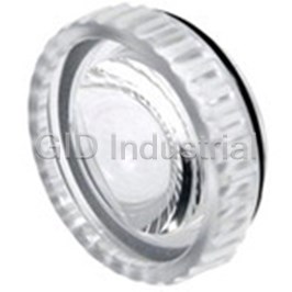
Digital Contrast Sensor With Metal Housing
95ACC1030
Part Number
95ACC1030
Price
Request Quote
Manufacturer
IDEC CORPORATION
Lead Time
Request Quote
Category
Sensors and Transducers » Specialized Sensor
Specifications
Manufacturer
IDEC Corporation
Manufacturers Part #
95ACC1030
Sub-Category
Specialized Sensors
Factory Pack Quantity
1
Datasheet

Extracted Text
Contrast: TL46 Sensors Contrast: TL46 Digital Contrast Sensor with Metal Housing • RGB LED • Automatic, manual and remote setting • 20kHz switching frequency • NPN/PNP and analog outputs • Standard mounting, M12 connector rotates in 5 positions The TL46 digital contrast sensor is characterized in terms of resolution, defi nition and precision of the light spot emitted by RGB LEDs, fast response time and high switching speed. The sensor, developed in a sturdy metal housing with standard mounting, is available for applications requiring innovative technol- ogy at the best price/performance ratio. The TL46-WL has 3 push-buttons to set the sensor, 4 LEDs signaling the output status, sensor acquisition condition, delay output activation and push-button activation. A bar graph is also available for manual setting of the threshold to detect particularly diffi cult contrasts. It also has a 20kHz switching frequency. Accessory lenses with 9 - 40mm focal distance are available, as well as a high-resolution focusing lens and a PMMA plastic lens particularly suitable for food applications with standard 9mm focal distance. 198 www.idec.com Communication & Networking Sensors Power Supplies Automation Software Operator Interfaces PLCs Communication & Networking PLCs Operator Interfaces Automation Software Power Supplies Sensors Contrast: TL46 Sensors Setting Dimensions (mm) The switching threshold is set by pressing twice on the SET button; the fi rst for the mark, the second for the background. 4 - M5 (depth 6mm) The threshold level can also be set manually by pressing the ‘+’ and ‘-‘ buttons, which increase or reduce the threshold as shown on the bar graph or display. 4 - M5 (depth 6mm) 2 - ø4 mounting holes Indicators & Settings Connection Green Ready LED Orange Delay LED +10 - 30V DC 1- 5.5V DC output Yellow Output LED Orange Keylock LED (brown) (white) 0V DC NPN/PNP output (blue) (black) Remote (gray) An M12 4-pole connector can be used if PIN5 function is not necessary. Bar Graph + / - Button + / - Button SET Button USA: 800-262-IDEC Canada: 888-317-IDEC 199 Contrast: TL46 Sensors Specifi cationsVertical Spot TL46-WL-815 1 Power Supply 10 - 30 V DC , reverse polarity protection √ Current Draw 85mA max. √ 2 Light Emission RGB LED (630nm red, 520nm green, 465nm blue) √ Spot Dimension 1.5 x 5mm (with standard 9mm lens) √ Spot Orientation Vertical √ Operating Distance 6 - 12mm (with standard 9mm lens) √ Depth Of Field ± 3 mm (with standard 9mm lens) √ Setting Automatic / manual / remote √ Yellow OUTPUT LED √ Green ready LED √ Indicators Orange delay LED √ Orange keylock LED √ 5-segment bargraph √ Output Type NPN/PNP programmable √ Output Current 100 mA max. √ Saturation Voltage ≤ 2 V √ Response Time 25μs √ Switching Frequency 20kHz √ Operating Mode Dark/light selectable √ Analog Output 0 - 5.5V (3V on 90% white) √ Timing Function 20ms programmable √ Auxiliary FunctionsKeylock √ 3 Connections M12 5-pole connector 3 √ Electrical Protection Class 2, double insulation √ Mechanical Protection IP67 √ 4 Protection Devices A, B √ Housing Material Aluminum √ Lens Material Glass √ Weight 170g max. √ Operating Temperature -10 to 55ºC √ Storage Temperature -20 to 70ºC √ II3D Reference Standard EN60947-5-2, UL508 √ 1. Limit values 2. Average life of 100,000 hrs with T = +25 ºC A 3. Connector block can rotate to 5 positions 4. A - reverse polarity protection B - overload and short-circuit protection 200 www.idec.com Communication & Networking Sensors Power Supplies Automation Software Operator Interfaces PLCs Communication & Networking PLCs Operator Interfaces Automation Software Power Supplies Sensors Contrast: TL46 Sensors Detection Diagrams 9mm Standard Lens 18mm Accessory Lens 22mm Accessory Lens (1.5 x 5mm spot at focal point) (2 x 7mm spot at focal point) (2 x 8mm spot at focal point) mm mm mm 28mm Accessory Lens 40mm Accessory Lens (2 x 9mm spot at focal point) (2.4 x 11mm spot at focal point) mm mm Part Number Function Version Spot Part Number For information on accessories, Standard Vertical TL46-WL-815 see page 229. Additional models are available. Visit www.idec-ds.com for more information. Connector Cables (for connector model sensors) Appearance Type & Length Use with Part No. TL46, LD46, 5m axial 5-pole DS1 (receiver), CS-A1-03-G-05 M12 cable AS1 (receiver) USA: 800-262-IDEC Canada: 888-317-IDEC 201 Communication & Networking PLCs Operator Interfaces Automation Software Power Supplies Sensors Accessories Sensors Application Sensors Accessories Brackets Diffuse-Refl ected Light Fiber Optic Unit Part Inspection Spot Sensing Range Use With Part Numbers Appearance Item Use with Number ø 2.5 mm 10mm SA9F-DA11 95ACC5330 ø 5 mm 20mm SA1J, SA1J-F SA9F-DA12 Mounting bracket (model ST-5020) S60, S62, ø 8 mm 30mm SA9F-DA13 S65 95ACC5340 Mounting bracket (model ST-5021) Lens Attachments L shaped mounting 95ACC2260 Description Use With Sensing Range Part Number S80 bracket (model ST-5037) SA9F-TS21 300mm For long range de- tection of opaque SA9F-TC21 200mm SA9Z-F11 objects SA9F-TM21 150mm SA9F-TS21 25mm Connector Cables (for connector model sensors) Sideview attach- SA9F-TC21 20mm SA9Z-F12 Appearance Type & Length Use with Part No. ment SA9F-TM21 20mm 5m axial 4-pole CS-A1-02-G-05 M12 cable S51, S60, S62, DS1 (emitter) Miscellaneous Accessories AS1 (emitter) 5m radial 4-pole CS-A2-02-G-05 Description Use with Part Number M12 cable HxLxD: 0.91” x 1.77” x All fi ber units except 0.31” (23x 45 x 8Dmm) Fiber cutter SA9Z-F01 5m axial 8-pole heat resistant Included with fi ber units; S65, S80 CS-A1-06-B-05 M12 cable order replacement only TL46, LD46, 5m axial 5-pole DS1 (receiver), CS-A1-03-G-05 M12 cable AS1 (receiver) 5m axial 4-pole M8 CS-B1-02-G-05 cable SR21 5m radial 4-pole M8 CS-B2-02-G-05 cable Lenses Part Appearance Item Use with Number Plastic lens with 9mm focus 95ACC2540 Plastic lens with 18mm focus 95ACC1030 TL46 Plastic lens with 22mm focus 95ACC1000 Plastic lens with 28mm focus 890000194 Plastic lens with 40mm focus TL46, LD46 95ACC1220 USA: 800-262-IDEC Canada: 888-317-IDEC 229 30º 4.5 ş4.1 R16 R20.5 ş4.4 20 10 R12.5 ş4.4 ş4.4 R12.5 28 ş4.4 35º = = 2 26.5 9 = = R16 ş4.3 ş5.1 ş4.1 R15 ş4.3 = = ş4.1 R40 R16 ş5.3 10º ş4.3 = = = = 16.5 20º 30º Accessories Sensors Dimensions (mm) 95ACC5330 (model ST-5020) 95ACC5340 (model ST-5021) 21 2 2 30º = = 8 20 = = 19 12 = = 28 50 40 2 5 95ACC2260 (model ST-5037) 230 www.idec.com Communication & Networking Sensors Power Supplies Automation Software Operator Interfaces PLCs Communication & Networking PLCs Operator Interfaces Automation Software Power Supplies Sensors Accessories Sensors Dimensions (mm) 95ACC2540 (model No. 9 PMMA) 95ACC1030 (model No. 18 glass) 95ACC1000 (model No. 22 glass) 9 31.5 5.5 28 4.5 890000194 (model No. 28 glass) 95ACC1220 (model No. 40 glass) 6 42 44 21.5 25.4 SA9Z-F01 Opening for fiber cables Opening for fiber USA: 800-262-IDEC Canada: 888-317-IDEC 231 Ø 25 M20x0.75 M20x0.75 Ø 33 Ø 25 Ø 18.8 Ø 18.8 M20x0.75 M20x0.75 Ø 33 Ø 28 M20x0.75 Laser Safety Sensors Laser Safety Information Installation: If a sensor is installed so that the laser beam may shine or refl ect into the eyes of a person passing by or working in the vicinity, place an opaque sheet of material in front of the beam to prevent potential eye injury. For people working near a laser sensor, protective glasses which screen out a signifi cant amount of the harmful radiation are recommended at all times. All laser sensors also include a remote interlock terminal which can be used to turn the laser on or off with an external switch, as required, to operate the sen- sor safely from a remote location. To avoid exposure to harmful radiation, never disassemble a laser sensor. WARNING: Do not allow class IIIa and IIIb laser beams to shine directly into the eyes. Do not allow lasers to refl ect from a glossy, shiny, or refl ective surface into the eyes. Labelling: IDEC laser sensors include CDRH-approved safety warnings shown below, in compliance with federal regulations of the Center for Devices and Radiological Health. MX1C Miniature Laser Sensor: Class IIIa Laser (670nm) Visible Beam All Laser Sensors: Identifi cation and Certifi cation mfd.: FEBRUARY 1997 Product conforms to 21 CFR1040 MX1C Visible Laser: Aperture Warning AVOID EXPOSURE – Laser light is emitted from this aperture. 232 www.idec.com Communication & Networking Sensors Power Supplies Automation Software Operator Interfaces PLCs Communication & Networking PLCs Operator Interfaces Automation Software Power Supplies Sensors General Information Sensors General Information Specifi cations Light Do not operate a sensor under any conditions exceeding these specifi cations. Visible light is electromagnetic radiation with a wavelength be- tween 390 and 770nm. White light is composed of all the vis- Do not operate a sensor under current and voltage conditions other than those ible spectrum components in equal quantity; the predominance of for which the individual sensor is rated. a specifi c wavelength determines the color of the light. Light Emit- ting Diodes (LEDs) are the most common light used in optoelectronics. Do not exceed the recommended operating temperature and humidity. Although sensors are rated for operation below 0°C, this specifi cation does not imply that performance characteristics will remain constant under prolonged freezing conditions. Continued exposure and the accompanying frost, ice, dew, and con- densation which accumulate on the optical surface will adversely affect sensor performance. To maintain performance characteristics, do not exceed vibration and shock resistance ratings while operating a sensor. In addition, avoid impacts to the sensor housing which are severe enough to adversely affect the waterproof characteristics. Transmission, Absorption, Refl ection When light hits an object three things take place at the same time: refl ection IEC (International Electrotechnical Commission) Ratings (ρ), absorption (α) and transmis- Sensors rated IP67 are resistant to moisture when occasionally immersed in sion (τ); with parameters and ratios water. Sensors rated IP64 through IP66 are resistant to moisture when occasion- that vary according to the object ally subjected to splashing or when located in the vicinity of turbulent waters. themselves, which are then further These ratings do not imply that a sensor is intended for use under continual differentiated by material, surface, thickness and/or color. These elements can high-pressure water spray. Avoid such applications to maintain optimal sensor be detected using a photoelectric sensor. performance. Sensors rated IP64 through IP67 are dust-tight and water-tight. For best perfor- Extraneous Light mance, avoid using any sensor in an area where it will be subjected to heavy Bright, extraneous light such as sunlight, incandescent lights, or fl uorescent particle blasts and where dust, water, or steam will accumulate on the optical lights may impair the performance of sensors in detecting color or light. surface. Make sure that extraneous light does not exceed recommended levels found in the individual specifi cations sections. When 500 lux is specifi ed, this is equal to Start-up 50 footcandles. The average factory illumination is ordinarily below this level, Do not test the housing for dielectric strength and insulation resistance, since except in areas where visual inspection is being performed. Only in such brightly the housing is connected to the electronic circuit ground of a sensor. Do not lit areas is incident light of particular concern. perform dielectric strength and insulation resistance tests on electrical systems without disconnecting photoelectric sensors, as such testing may result in dam- Unwanted light interference can often be avoided simply by making sure that the age to the sensor. optical receiver is not aimed directly toward a strong light source. When mount- ing direction cannot be adjusted, place a light barrier between all nearby light Several lines of sensors, as noted in the individual operation sections, are pro- sources and the receiver. vided with an internal circuit to turn an output off for a specifi ed amount of time upon power-up. This delay is normal; it prevents a transient state when turning power on. Through-beam Sensors With through-beam sensors, the light emitter and receiver are contained in two different housings that are mounted one in front of Optimum Performance the other. The light beam emitted by the emitter directly hits the The optical surface of each sensor must be cleaned on a regular basis for receiver; each object that interrupts the beam is detected. This system is used to continual superior performance. Use a soft cloth dipped in isopropyl alcohol to obtain large signal differences remove dust and moisture build-up. (when the light directly hits the IMPORTANT: Do not use organic solvents (such as thinner, ammonia, caustic receiver and when the object soda, or benzene) to clean any part of a sensor. interrupts the beam) with the highest Excess Gain and the All sensors experience signal inconsistencies under the infl uence of inductive largest operating distance reaching noise. Do not use sensors in close proximity to transformers, large inductive up to 50m. These sensors can motors or generators. Avoid using sensors in direct contact with sources of operate in the harshest environ- excessive heat. Also avoid operation in close proximity to welding equipment. mental conditions, such as in the presence of dirt or dust. The disadvantage is that two units have to be wired (an emitter and receiver). The through-beam optic function operates typically in dark mode: the output is activated when the object interrupts the beam between the emitter and receiver. It is strongly recommended to avoid using any sensor where it will be continually subjected to elements which impair performance or cause corrosive damage to the sensor. In particular, avoid strong vibrations and shocks, corrosive gases, oils and chemicals, as well as blasts of water, steam, dust or other particles. USA: 800-262-IDEC Canada: 888-317-IDEC 233 General Information Sensors A slit attachment is available to modify the beam size of through-beam sensors. Retro-refl ective for Transparent Objects This option is recommended for detecting very small objects (near the size of the For detection of transparent objects, such as PET bottles or Mylar smallest object which a sensor can detect) or for eliminating light interference sheets, a low-hysteresis retro-refl ective sensor (capable of detecting when sensors are mounted in close proximity. small signal differences) can be used. These sensors detect small signal differences that the light undergoes when it passes through a transparent Retro-refl ective object. Photoelectric sensors with this function contain both the emitter and receiver inside the same Diffuse Proximity housing. The emitted Photoelectric sensors with this function contain both the emitter and light beam is refl ected on the receiver inside the same housing. The emitted light beam is refl ected receiver due to a prismatic on to the receiver directly by the object, which is detectedwithout the refl ector; an object is detected need of prismatic refl ectors. Proximity when it interrupts the beam. sensors represent the most economic Compared to the through-beam and fastest mounting solution. optic function, the signal However, they work with weaker difference is reduced (when the signals compared to retro-refl ective light is freely refl ected by the sensors. Excess Gain is reduced and refl ector and when an object operating distance, depending on the interrupts the beam) so Excess Gain is reduced and maximum operating object’s refl ection degree, can only distances can reach 12 meters. It is necessary to operate in clean environments reach 2 meters. without dirt or dust. A retro-refl ective sensor typically operates in the dark mode: A proximity sensor normally operates output is activated when an object interrupts the light beam between the sensor in light mode: the output is activated when an object enters the detection area and refl ector. and refl ects light emitted by the sensor. When installing sensors which detect refl ected light, make sure that unwanted light refl ections from nearby surfaces, such as the fl oor, walls, refl ective machin- Background Suppression ery or stainless steel, do not reach the optical receiver. Background suppression sensors allow the operator to precisely set the Also, make sure that refl ected-light sensors mounted in close proximity do not maximum detection distance. The operating distance adjustment is not cause interfering refl ections. When it is not possible to maintain the recommend- based upon the receiver’s ed clearance between sensors, as noted in the individual installation sections, sensitivity, but is obtained through provide light barriers between sensors. optic triangulation, mechanically acting on the lenses or photoelements angle or electronically using PSD Prismatic Refl ector (Position-Sensitive Detectors) A prismatic refl ector is able to refl ect incident light in a parallel manner, with a receiving systems. Consequently the refl ection coeffi cient higher than any other object for angles less than 15°. Typi- detection of an object is independent cally the operating distance proportionally increases according to the refl ector’s of other objects behind (or in the dimensions. The refl ector can rotate the incident light’s polarization plane at 90°. background), which are suppressed. Retro-reţ ection Moreover, due to this adjustment with prismatic reţ ector method, all objects can be detected at the same distance independent of Retro-reţ ection their color. with ţ at reţ ective surface Distance Sensors Distance sensors supply an analog signal of 0-10V or 4-20mA propor- tional to the measurement of the distance between the emitting optics Polarized Retro-refl ective and the target. In presence of critical detection of objects with very refl ective surfaces, such as shiny metals or mirrored glass, retrorefl ex sensors with polar- The main technologies involved are optic triangulation and time-of-fl ight. The ized fi lters have to be used. In polarized retrorefl ex sensors, the emis- fi rst allows very precise measurements on short distances, while the second is sion light is polarized on a vertical plane, while the reception is obtained only ideal for medium and long distances. through a polarized fi lter on a horizontal plane. A prismatic refl ector rotates the light plane at a right angle, while the light refl ected from the object maintains polarization plane unvaried and is blocked by the fi lter placed on the receiver. Consequently, only the light refl ected by the prismatic refl ector is received. 234 www.idec.com Communication & Networking Sensors Power Supplies Automation Software Operator Interfaces PLCs Communication & Networking PLCs Operator Interfaces Automation Software Power Supplies Sensors General Information Sensors Slot Sensors Luminescence Sensors A slot sensor is a version of a through-beam retro-refl ective sensor, ‘Luminescence’ is defi ned as visible light emission from fl uorescent or where the emitter and receiver are phosphorous substances, due to electromagnetic radiation absorption. placed opposite each other on the Luminescence sensors emit ultraviolet light, which is refl ected at a inside of an U-shaped housing. Any target that higher wavelength (minor energy) on a passes through the internal slot interrupts the fl uorescent surface, shifting into the beam and is detected. Due to their construction, visible light spectrum. Ultraviolet light slot sensors are great for applications with short emission is obtained using special operating distances. The most typical slot sensor lamps, or LEDs in sensors. UV applications are hole or teeth detection on gears, emission is modulated and the visible label detection, or edge control and continuity of light reception is synchronized. sheets or tapes. The emission is generally Maximum immunity against external infrared light; however visible red or green interferences, such as refl ections emission versions are available and able to detect references such as registra- caused by very shiny surfaces, is tion marks, that present color contrasts on transparent fi lm. obtained. In addition, fl uorescent targets, invisible to the human eye, can be detected. Luminescence sensors are used in various industries: detecting labels on glass or mirrors in pharmaceutical and cosmetic fi elds; selecting tiles marked Contrast Sensors with fl uorescent marks in the ceramic industry; determining the presence of Contrast sensors (also defi ned as color mark readers) present a fl uorescent glues on paper for automatic packaging; distinguishing cutting and proximity function but, instead of detecting only the presence or sewing guides in textile manufacturing; checking fl uorescent paints or lubricants absence of an object, they are able to distinguish between two in mechanical production. surfaces. This accomplished by detecting the contrast produced by Color Sensors the different refl ection degrees. In The color of an object depends on all the color components of the this manner a dark reference mark incident light which are being refl ected, eliminating those which have (low refl ection) can be detected been absorbed. The dominant color is defi ned as ‘hue’ and depends on due to the contrast with a lighter the refl ected light’s wave- surface (high refl ection), or vice length. ‘Saturation’ indicates versa. In the presence of colored the pureness of the color with surfaces, the contrast is highlight- respect to white and is ed using an LED, typically red or represented as a percentage. green. For general purposes a white light is used because the full light spectrum Hue and saturation together detects the majority of contrasts. White light emission is obtained through are defi ned as ‘chromaticity’. lamps, or LEDs in most sensors, enabling the detection of very slight contrasts due to different surface treatments, even of the same material and color. Color or chromatic sensors have a proximity function with Contrast sensors are mainly used in automatic packaging machines for registra- generally three RGB LEDs for tion mark detection to synchronize folding, cutting and welding. light emission. The color of an object is identifi ed according to the different refl ection coeffi cients obtained Contrast on White Background with red (R), green (G) and blue (B) light emissions. More simply, yellow can be Mark Color Red LED Green LED White LED identifi ed by R=50% G=50% B=0% refl ections; orange by R=75% G=25% B=0% refl ections; pink by R=50% G=0% B=0% refl ections; but possible combinations Red no medium medium are really infi nite. Color sensors operate only on refl ection ratios and are not in- Orange low medium medium fl uenced by light intensity, defi ned as ‘brilliance ‘or ‘luminance’. There is a wide Yellow low low medium range of applications, ranging from quality and process controls, to automatic Green high no medium material handling for identifi cation, orientation and selection of objects accord- ing to color. Blue high medium high Violet medium high high Fiber Optic Sensors Brown low medium high Universal functions of through-beam and proximity sensors, as well as Black high high high application functions ranging from contrast and luminescence to color detection, can be obtained using fi ber optic sensors. The optical fi bers Gray medium medium medium can be thought of as cables that transport light and can be used to place the White no no yes sensor’s optics in small spaces, or to detect very small objects. An optical fi ber is composed of cylindrical glass (or a plastic core), surrounded by Tefl on or Silicon coating. The difference between the core and the coating refraction indexes allows the light to be diffused inside the fi ber in a guided manner. The coating is covered by a plastic or metal sheath, which has an exclu- sively mechanical protection function. Fibers with a glass core and metal sheath are suitable for very high temperature uses, or for particular mechanical require- ments. Plastic fi bers, offering great adaptability, are the most diffused in all USA: 800-262-IDEC Canada: 888-317-IDEC 235 General Information Sensors applications. Plastic optic fi bers have a standard 2.2mm external diameter and When extending sensor cables and wires, make sure to use cables equal or generally have a cylindrical threaded metal head on the end used for mechanical superior to that recommended in the individual specifi cations sections. mounting. These fi bers are usually 1 and 2 meters in length as reductions in per- When wiring terminals, be sure to prevent contact between adjoining terminals. formance become signifi cant with lengths over 5 meters. Plastic optic fi bers can When using ring or fork lug terminals, use the insulated sleeve style only. Each be shortened using a special fi ber-cutting tool, but, it can only be used a limited sensor terminal can accept only one ring or fork lug terminal. number of times. Cutting the fi ber with a non-sharp or non-perpendicular blade will reduce operating distance. High temperature, extra-fl exible or high effi ciency plastic optic fi bers are also available. Power Supply Noise resistance characteristics are improved when a sensor is grounded to the 0V power terminal. If the 0V power terminal is not at ground potential, use a ceramic 0.01μF capacitor which can withstand 250V AC minimum. When using a switching power supply, be sure to ground the FG terminal to eliminate high-frequency noise. The Proximity Ţ bers power supply should include an insulating transformer, not Through-beam Ţ bers an autotransformer. The compact PS5R-A power supply is the perfect compan- ion item for most IDEC sensors. This power supply is only 1.77” (45mm) wide, 3.15” (80mm) tall, and 2.76” (70mm) deep. Call an IDEC representative for more details. Laser Sensors A LASER (Light Amplifi cation by Stimulated Emission of Radiation) is Part Number Output Ratings an electronic device, such as a diode, that converts an energy source PS5R-A12 12V DC, 0.62A into a very thin and concentrated light beam, suitable for detecting PS5R-A24 24V DC, 0.32A very small objects or to reach very long operating distances. With reference to the safety of laser radiation (according to the EN60825-1 European standard) class 1 requires that the laser device is safe under Miscellaneous reasonable operating conditions and is not dangerous Strong magnetic fi elds may detract from the accuracy of the sensing measure- for people in any situation; while class 2 states that ments. Avoid mounting a sensor directly to machinery, since the housing is con- the eye cannot be protected just by looking away or nected to the electronic circuit ground of the sensor. If it is necessary to mount a blinking, thus precautions must be adopted to avoid sensor on machinery, use the insulating plate and sleeve provided. staring into the beam. IMPORTANT: Always consider safety when installing a laser sensor of any kind. Make sure that the laser beam cannot inadvertently shine into the eyes of people passing by or working in the vicinity. See safety information on page 232. Mounting Mounting brackets and hardware are included with sensors, where applicable. Use the hardware for mounting, along with washers and spring washers or lock nuts. Do not overtighten hardware. Overtightening causes damage to the hous- ing and will adversely affect the waterproof characteristics of the sensor. Best results can be obtained when the sensor is mounted so that the object sensed is in the center of the beam, rather than when the object is located near the edges of the sensing window. In addition, the most reliable sensing occurs when the majority of the objects being sensed are well within the sensing range, rather than at the extreme near and far limits. Wiring Avoid running high-voltages or power lines in the same conduit with sensor signal lines. This prevents inaccurate results or damage from induced noise. Use a separate conduit when the infl uence of power lines or electromagnetic equip- ment may occur, particularly when the distance of the wiring is extended. IMPORTANT: Connect the sensor cables and wires as noted in the individual Wiring sections. Failure to connect as shown in wiring diagrams will result in damage to the internal circuit. 236 www.idec.com Communication & Networking Sensors Power Supplies Automation Software Operator Interfaces PLCs Communication & Networking PLCs Operator Interfaces Automation Software Power Supplies Sensors General Information Sensors Glossary Attenuation: Reduction of beam intensity as a result of environmental factors Retro-refl ective: This type of refl ected light sensor uses a special refl ector to such as dust, humidity, steam, etc. return projected light when an object is not present. Sensor detects the presence of an object when the light is refl ected differently. Dark on: Output energized when light is not detected by the receiving element. For through-beam sensors, light from the projector is not detected by the re- Through-beam sensors: Sensors with a separate projector and receiver. The ceiver when an object is present. For refl ected light sensors, light is not detected light source from the projector is detected by the receiver, except when an object when it is not refl ected from an object surface. is present. Diffuse-refl ected light sensors: Sensors that detect all scattered and re- Transient: Undesirable surge of current (many times larger than normal current) fl ected light. Light refl ected from nearby surfaces, as well as the intended object for a very short period, such as during the start-up of an inductive motor. surface, is detected. Diffuse-refl ected light sensors are often called “proximity switches,” since they switch when any object is near. Also use to detect color contrast when colors refl ect light intensity differently (green LED recommended for this application). EEPROM: Acronym which stands for electronically erasable, programmable, read only memory. Excess gain: Ratio of optical power available at a given projector-to-receiver range divided by the minimum optical power required to trigger the receiver. Extraneous light: Incident light received by a sensor, not related to the presence or absence of an object being detected. Extraneous light is usually unwanted background light such as sunlight and incandescent lamps in close proximity. ΔE: The measurement of color difference as a three-variable function, located on an XYZ axis of light, hue, and chroma values. Hysteresis: The lag in response shown by an object in reacting to changes in the forces affecting it . Operating point and release point at different levels. For solid state sensors, this is accomplished electrically. For mechanical switches, it results from storing potential energy before the transition occurs. Light on: Output energized when light is detected by the receiving element. For through-beam sensors, light from the projector is detected by the receiver when an object is not present. For refl ected light sensors, light is detected when it is refl ected from an objects surface. Linearity: The measure of the extent to which a certain response is directly proportional to the applied excitation. NPN/PNP: Types of open collector transistors. NPN is a sink transistor; output on establishes negative potential difference. PNP is a source transistor; output on establishes positive potential difference. Polarizing: Filtering out all refl ected light except that which is projected in one plane only. Polarized retro-refl ected light sensors detect the light from corner- cube type refl ectors when an object is not present. Refl ected-light sensors: Sensors with the projector and receiver in one hous- ing. Light is projected by the light source, and refl ected light is received by the optical surface. Includes diffuse-refl ected, retro-refl ected, limited-refl ected, and spot-refl ected sensors. Repeatability: Ability of a sensor to reproduce output readings consistently when the same value is applied consecutively, in the same direction, for a speci- fi ed number of cycles, or for a specifi ed time duration. Resolution: Overall dimension of the smallest object which can be detected (when sensing the presence of an object) or smallest increment of distance which can be distinguished with reliable results (when sensing the position of an object). Response time: Time elapsed between input and output. Total response time is the sum of object detection, amplifi er response, and output response times. USA: 800-262-IDEC Canada: 888-317-IDEC 237
Frequently asked questions
How does Electronics Finder differ from its competitors?

Is there a warranty for the 95ACC1030?
Which carrier will Electronics Finder use to ship my parts?
Can I buy parts from Electronics Finder if I am outside the USA?
Which payment methods does Electronics Finder accept?
Why buy from GID?

Quality
We are industry veterans who take pride in our work

Protection
Avoid the dangers of risky trading in the gray market

Access
Our network of suppliers is ready and at your disposal

Savings
Maintain legacy systems to prevent costly downtime

Speed
Time is of the essence, and we are respectful of yours
Related Products
Digital Contrast Sensor With Metal Housing 95ACC2260
Digital Contrast Sensor With Metal Housing 95ACC2540
Digital Contrast Sensor With Metal Housing 95ACC5340
Light Grid Sensor AS1-HD-HR-010-J
Reflector Sensor 4-Pin CS-A1-02-G-05
Analog Distance Detection sensor CS-A1-03-G-05
Request a Quote

The quote request has been received
Close

Facing challenges or have inquiries? Feel free to contact us!
Call Us +1-469-283-2440
What they say about us
FANTASTIC RESOURCE
One of our top priorities is maintaining our business with precision, and we are constantly looking for affiliates that can help us achieve our goal. With the aid of GID Industrial, our obsolete product management has never been more efficient. They have been a great resource to our company, and have quickly become a go-to supplier on our list!
Bucher Emhart Glass
EXCELLENT SERVICE
With our strict fundamentals and high expectations, we were surprised when we came across GID Industrial and their competitive pricing. When we approached them with our issue, they were incredibly confident in being able to provide us with a seamless solution at the best price for us. GID Industrial quickly understood our needs and provided us with excellent service, as well as fully tested product to ensure what we received would be the right fit for our company.
Fuji
HARD TO FIND A BETTER PROVIDER
Our company provides services to aid in the manufacture of technological products, such as semiconductors and flat panel displays, and often searching for distributors of obsolete product we require can waste time and money. Finding GID Industrial proved to be a great asset to our company, with cost effective solutions and superior knowledge on all of their materials, it’d be hard to find a better provider of obsolete or hard to find products.
Applied Materials
CONSISTENTLY DELIVERS QUALITY SOLUTIONS
Over the years, the equipment used in our company becomes discontinued, but they’re still of great use to us and our customers. Once these products are no longer available through the manufacturer, finding a reliable, quick supplier is a necessity, and luckily for us, GID Industrial has provided the most trustworthy, quality solutions to our obsolete component needs.
Nidec Vamco
TERRIFIC RESOURCE
This company has been a terrific help to us (I work for Trican Well Service) in sourcing the Micron Ram Memory we needed for our Siemens computers. Great service! And great pricing! I know when the product is shipping and when it will arrive, all the way through the ordering process.
Trican Well Service
GO TO SOURCE
When I can't find an obsolete part, I first call GID and they'll come up with my parts every time. Great customer service and follow up as well. Scott emails me from time to time to touch base and see if we're having trouble finding something.....which is often with our 25 yr old equipment.
ConAgra Foods