

 Manufacturers
IDEC CORPORATION ABN1B-Y

Description
Switch Access Push Button Switch Flush Button
ABN1B-Y
Part Number
ABN1B-Y
Price
Request Quote
Manufacturer
IDEC CORPORATION
Lead Time
Request Quote
Category
Sensors and Transducers » Switch Accessories
Specifications
Manufacturer
IDEC Corporation
Manufacturers Part #
ABN1B-Y
Industry Aliases
ABN1B-Y
Sub-Categories
Switch Accessories
Factory Pack Quantity
1
Datasheet

Extracted Text
ø30 Series Control Units ø30 ø30 Series Control Units (Selection Guide) Function Emergency Stop Switch Pushbutton Extended with Extended with Flush Extended Half Shroud Full Shroud Category Pushlock Turn Reset Momentary/Maintained Shape (Diecast) (Diecast) (Diecast) (Diecast) ABN1 ABN2 ABN2G ABN2F Type HN1E ABD1 ABD2 ABGD2 ABFD2 AON1 AON2 AON2G AON2F AOD1 AOD2 AOGD2 AOFD2 Page 6 13 69136913691369 Function Pushbutton Mushroom with Jumbo Mushroom with Jumbo Mushroom with Mushroom Palm Mushroom Full Shroud Shallow Shroud Deep Shroud Category Momentary/Maintained Momentary Shape (Diecast) (Diecast) ABN3 (Diecast) (Diecast) (Diecast) Type ABD3 ABN3G ABGD3 ABN4 ABN4G ABN4F AON3 ABD4 ABGD4 ABFD4 AOD3 AOGD3 Page 14 70 14 70 14 70 14 70 14 70 Function Pushbutton Square Flush Square Extended Mushroom Pushlock Mushroom Pushlock Jumbo Mushroom Category Turn Reset Key Reset Pushlock Key Reset Momentary Momentary Shape (Diecast) Type UBQN1 UBQN2 AVN3 ABN3K ABN4K AVD3 Page 14 14 15 71 15 15 Function Pushbutton Mushroom Push Category Key ON/OFF Lock Toggle Lever Mushroom Pull Mushroom Push-Pull Turn Lock Shape (Diecast) (Diecast) ATN21 (Diecast) Type AJN3 ABN5 ATN4 ATN23 AJD3 AZD3 ATN22 AYD3 Page 15 71 15 15 16 71 16 71 2 ø30 Series Control Units (Selection Guide) ø30 Function Pushbutton Twin Maintained Pushbutton Square Twin Square Twin Category Pin Lock Flush Mushroom Momentary Maintained Shape (Diecast) Type ABN8P UWQN1 UWQN2 ABBN11 ABBN33 ABD8P Page 16 71 17 17 17 17 Function Pilot Light (LED) Pilot Light (Incandescent) Category Dome Square Rectangular (Marking) Dome (1W) Dome (2W) Shape (Diecast) (Diecast) APN1 UPQN4 (Diecast) APN1 Type APD1 UPQN3B APN1 APD1 APNE1 UPQNE4 APNE1 APD1 APDE1 APDE1 Page 18 72 19 19 19 72 18 72 Function Pilot Light (Incandescent) Illuminated Pushbutton (LED) Extended with Rectangular (Marking) Dome Extended Half Shroud Category Square Flush (1W) (1W/2W) Push-to-Check Momentary/Maintained Shape ALN2 ALGN2 (Diecast) UPQN4 ALNE2 ALGNE2 Type UPQN3B APN1∗P ALD2 UPQNE4 AOLN2 AOLGN2 AOLD2 AOLNE2 AOLGNE2 Page 19 19 21 22 73 24 Function Illuminated Pushbutton (LED) (Incandescent) Extended with Mushroom Extended Mushroom Pushlock Mushroom Push Full Shroud Category Turn Reset Turn Lock Momentary/Maintained Momentary/Maintained Shape ALFN2 ALN3 ALN (Diecast) (Diecast) (Diecast) (Diecast) ALFNE2 ALNE3 AVLN3 ALNE Type ALFD2 ALD3 AVLD3 AJLN3 ALD2 AOLFN2 AOLN3 AVLNE3 AOLN AOLFD2 AOLD3 AVLDE3 AOLD2 AOLFNE2 AOLNE3 AOLNE Page 26 74 28 75 31 76 31 23 73 3 ø30 ø30 Series Control Units (Selection Guide) Function Illuminated Pushbutton (Incandescent) Extended with Extended with Square Flush Rectangular Half Shroud Full Shroud Category Turn Lock Momentary Momentary/Maintained Momentary/Maintained Shape ALN∗F (Diecast) ALN∗G ALNE3F3 ULQN ULQN∗B Type ALFD2 ALN∗L ALNE3G3 AOLN∗F UOLQN UOLQN∗B AOLFD2 AOLNE3F3 Page 25 27 74 29 29 30 Function Illuminated Pushbutton (Incandescent) Selector Switch Mushroom Pushlock Mushroom Push Category Knob Lever Key Turn Reset Turn Lock Shape (Diecast) (Diecast) (Diecast) (Diecast) AVLN3 ASN ASN∗L ASN∗K Type AJLN3 AVLD3 AVLNE3 ASTN ASD ASTN∗L ASD∗L ASTN∗K ASD∗K AVLDE3 Page 32 76 32 33/37 77 34/38 78 35/39 79 Illuminated Selector Illuminated Selector Function Selector Pushbutton Mono-Lever Switch Switch (LED) Switch (Incandescent) Category Knob Knob Ring Lever Standard Shape (Diecast) (Diecast) (Diecast) (Diecast) ARN Type ASLN ASLN ABN ABN∗L ASLD ASLD ASBD2 ASBD2L ARNS Page 40 80 40 80 42 82 42 82 44 Function Mono-Lever Switch Cam Switch Maintained/ Category Interlocking Knob Key Spring Return Spring Return Shape ACSNO ACSNK Type ARNL UCSQO UCSQM ACSSO ACSSK Page 44 47 47 47 47 4 ø30 HN Series Emergency Stop Switches Emergency Stop Switches (Unibody Type) Specifications Contact Ratings Specifications Rated Insulation Voltage (Ui) 250V Operating –25 to +60°C (no freezing) Temperature Illuminated units: –25 to +55°C Rated Thermal Current (Ith) 10A Storage Temperature –40 to +80°C Rated Operational Voltage (Ue) 24V 110V 220V Operating Humidity 45 to 85% RH (no condensation) Resistive Load 6A 3A 3A AC (AC-12) Contact Resistance 50 mΩ maximum (initial value) 50/60 Inductive Load Insulation Resistance 100 MΩ minimum (500V DC megger) Hz 6A 3A 3A Rated (AC-15) Between live and dead metal parts Operational Resistive Load Dielectric Strength Contacts: 2,500V AC, 1 minute Current 6A 2A 1A (DC-12) Illuminated parts: 1,000V AC, 1 minute DC 2 Inductive Load Damage limits: 60 m/s 1.5A 0.3A 0.15A (DC-13) Vibration Resistance Operating extremes: 5 to 55 Hz, amplitude 0.5 mm Note: The operational current represents the classification by 2 making and breaking currents (IEC 60947-5-1). Damage limits: 1,000 m/s Shock Resistance 2 Minimum applicable load (reference value): 3V AC/DC, Operating extremes: 100 m/s 5 mA (Applicable range may vary with operating condi- Operating Frequency 900 operations/h tions and load types.) Mechanical: 250,000 operations minimum Life Electrical: 100,000 operations minimum LED Lamp Ratings Degree of Protection IP65 LED Lamp Unit Rated Terminal Style M3.5 screw Operating Rated Type No. Rated Voltage Voltage Current Applicable Standards and Approvals 24V AC/DC LSTD-2R 24V AC/DC ±10% 10 mA Safety Standards File No. or Organization UL508 UL Listing File No. E55996 Incandescent Lamp Ratings CSA C22.2 No. 14 c-UL (File No. E55996) Unit Rated Incandescent Lamp EN60947-5-5 DEMKO approved Operating Type No. Wattage Voltage 24V AC/DC LS-3 1W (30V) Pushlock Turn Reset Switches (Unibody Type) Shape Contact Type No. Button Color 1NO-1NC HN1E-BV411R Red only 2NC HN1E-BV402R • When pressed, the button is held depressed. The button is released by turning clockwise. • Terminal cover HW-VL7 is supplied with the switch. Illuminated Pushlock Turn Reset Switches (Unibody Type) Shape Lamp Contact Type No. Lens Color 1NO-1NC HN1E-LV411Q0R Without Lamp Red only 2NC HN1E-LV402Q0R • When pressed, the button is held depressed. The button is released by turning clockwise. • The illuminated pushlock turn reset switch does not contain a lamp. Order LED or incandescent lamps separately. For lamps, see page 63. • Terminal cover HW-VL7 is supplied with the switch. 5 ø 40 ø 40 +0.5 ø 30.5 0 ø 30 R0.8 max. ø30 HN Series Emergency Stop Switches Dimensions Panel Cut-Out • HN1E-BV4 M3.5 Terminal Gasket Screw Panel Thickness 0.8 to 6 +0.2 4.8 0 0.5 Terminal Arrangement Locking Ring (Bottom View) TOP Marking Side 23.5 61 63 32 • HN1E-LV4 M3.5 Terminal Screw Gasket Panel Thickness 0.8 to 6 M3.5 Terminal Screw Terminal Arrangement 0.5 (Bottom View) Lamp Terminal Locking Ring TOP Marking Side X1 LAMP X2 23.5 61 All dimensions in mm. 63 32 Replacement Parts Name Type No. Ordering Type No. Package Quantity Remarks Used on HN1E emergency stop switches for preventing Terminal Cover HW-VL7 HW-VL7PN10 10 electrical shocks. The HW-VL7 terminal cover is supplied with the HN1E. Nameplates Package Shape Type No. Legend Remarks Quantity Background: Yellow Legend: Black HNAV-0 (blank) Applicable panel thickness: 0.8 to 4.5 mm Material: Polyamide 1 Legend “EMERGENCY STOP” is indicated outside a ø44mm circle. EMERGENCY 1.5 1.0 HNAV-27 STOP Accessory Package Shape Material Type No. Remarks Quantity • Used for tightening the locking nut. • Tighten the locking nut to a torque of 2.0 to 2.5 N·m. Metal TWST-T1 1 23.7 77 6 ø 60 49.5 33 52 20.5 ø30 ø30 Series Control Units Heavy duty control units offer both variety and reliability Endures harsh environments • Degree of protection: IP65 • UL, CSA approved, and EN compliant. Safety Standards File No. or Organization UL Listing UL File No. E68961 CSA File No. LR21451 EN EN60947-5-1 Specifications and Ratings Contact Ratings Contact Block Type BS/BST (ø30 series) Pushbuttons Rated Insulation Voltage 600V Illuminated Pushbuttons Selector Switches Rated Continuous Current 10A Illuminated Selector Switches Contact Ratings by Utilization Category AC-15 (A600) Selector Pushbuttons IEC 60947-5-1 DC-13 (P600) Characteristics • Contact Ratings by Utilization Category Operational Voltage 24V 48V 50V 110V 220V 440V AC-12 Control of resistive loads and solid state loads 10A — 10A 10A 6A 2A AC 50/60 Hz AC-15 Control of electromagnetic loads (> 72 VA) 10A — 7A 5A 3A 1A Operational Current DC-12 Control of resistive loads and solid state loads 10A 5A — 2.2A 1.1A — DC DC-13 Control of electromagnets 5A 2A — 1.1A 0.6A — Note: The operational current represents the classification by making and breaking currents (IEC 60947-5-1). Minimum applicable load: 3V AC/DC, 5 mA (applicable range may vary with operating conditions and load types) For mono-levers and cam switches, see pages 43 and 46. BS (BST) Contact Block • Contact Block Types Single-pole Contact Block Type • Interlocking Groove Contact • Mounting • M3.5 Terminal Screw 1NO 1NC 1NO (early make) 1NC (late break) Screw BS BS010E BS001E BS010SE BS001SE Type BST BST010 BST001 BST010S BST001S Push Rod Green Red Black White BST contact blocks are used for the following control units and are not interchangeable with BS contact blocks. (The BS housing is dark gray and the BST housing is light gray.) • Pushlock turn reset and push turn lock switches • LED illuminated pushbuttons • Inspection • Push Rod • LED/incandescent illuminated selector switches Window • All models of diecast zinc housing control units • Durable nylon 66 housing has a high resistance against alkalis. • Silver contacts. • Up to four blocks in two layers can be mounted onto each operator. 7 ø30 ø30 Series Control Units LED Illuminated Unit Specifications LED Lamp Unit Color Code ➁Input Type Operating Voltage Lamp Base Type No. Voltage 6V AC/DC LSTD-6➁6V AC/DC ±10% 12V AC/DC BA9S/13 LSTD-1➁12V AC/DC ±10% 24V AC/DC LSTD-2➁24V AC/DC ±10% Full Voltage 6V AC/DC LETD-6➁6V AC/DC ±10% 12V AC/DC E12/15 LETD-8➁12V AC/DC ±10% A: amber 24V AC/DC LETD-2➁24V AC/DC ±10% G: green 100/110V AC/DC Pilot Light PW: pure white 115V AC/DC Illuminated Pushbutton R: red BA9S/13 LSTD-6➁ 120V AC/DC S: blue Illuminated Selector Switch 200/220V AC/DC W: white Transformer 230V AC/DC 6V AC/DC ±10% Y: yellow 240V AC/DC 380V AC/DC E12/15 LETD-6➁ 400/440V AC/DC (50/60 Hz) BA9S/13 LSTD-6➁ DC-DC Converter 110V DC 6V AC/DC ±10% E12/15 LETD-6➁ Incandescent Illuminated Unit Specifications Incandescent Lamp Unit Color Code ➁Input Type Operating Voltage Lamp Base Type No. Rating 6V AC/DC LS-6 1W (6.3V) 12V AC/DC BA9S/13 LS-8 1W (18V) 24V AC/DC LS-3 1W (30V) Full Voltage 6V AC/DC LE-6 2W (6.3V) 12V AC/DC E12/15 LE-8 2W (18V) A: amber 24V AC/DC LE-3 12W (30V) G: green Pilot Light 100/110V AC/DC O: orange Illuminated Pushbutton 115V AC/DC R: red Illuminated Selector Switch BA9S/13 LS-6 1W (6.3V) 120V AC/DC S: blue 200/220V AC/DC W: white 230V AC/DC Transformer 240V AC/DC 380V AC/DC 400/440V AC/DC E12/15 LE-8 2W (18V) 480V AC/DC (50/60 Hz) LED Lamp Ratings (LSTD Type) Type No. LSTD-6➁LSTD-1➁LSTD-2➁ Lamp Base BA9S/13 Rated Voltage 6V AC/DC 12V AC/DC 24V AC/DC Voltage Range 6V AC/DC ±10% 12V AC/DC ±10% 24V AC/DC ±10% A, R, W, Y: 17 mA AC 11 mA 11 mA G, PW, S: 8 mA Current Draw A, R, W, Y: 14 mA DC 10 mA 10 mA G, PW, S: 5.5 mA Color Code ➁A (amber), G (green), PW (pure white), R (red), S (blue), W (white), Y (yellow) Lamp Base Color Same as illumination color Voltage Marking Die stamped on the base Approx. 50,000 hours Life (reference value) (The luminance is reduced to 50% the initial intensity when used on complete DC.) A, R, W, Y A, R, W, Y Internal Circuit G, PW, S LED Chip Protection Diode Zener Diode 8 ø30 Series Control Units ø30 LED Lamp Ratings (LETD Type) Type No. LETD-6➁LETD-8➁LETD-2➁ Lamp Base E12/15 Rated Voltage 6V AC/DC 12V AC/DC 24V AC/DC Voltage Range 6V AC/DC ±10% 12V AC/DC ±10% 24V AC/DC ±10% A, R, W, Y: 17 mA AC 7 mA 11 mA G, S: 8 mA Current Draw A, R, W, Y: 14 mA DC 6.5 mA 10 mA G, S: 5.5 mA Color Code ➁A (amber), G (green), R (red), S (blue), W (white), Y (yellow) Lamp Base Color Same as illumination color Voltage Marking Die stamped on the base Approx. 50,000 hours Life (reference value) (The luminance is reduced to 50% the initial intensity when used on complete DC.) A, R, W, Y A, R, W, Y Internal Circuit G, S LED Chip Protection Diode Zener Diode Incandescent Lamp Ratings (LS Type) Type No. LS-6 LS-8 LS-2 LS-3 Lamp Base BA9S/13 Rated Voltage 6V AC/DC 12V AC/DC 18V AC/DC 24V AC/DC Wattage 1W (6.3V) 1W (18V) 1W (24V) 1W (30V) Voltage Marking Die stamped on the base Approx. 1,000 hours minimum Life (reference value) (mean value when used on the rated voltage) Incandescent Lamp Ratings (LE Type) Type No. LE-6 LE-8 LE-2 LE-3 Lamp Base E12/15 Rated Voltage 6V AC/DC 12V AC/DC 18V AC/DC 24V AC/DC Wattage 2W (6.3V) 2W (18V) 2W (24V) 2W (30V) Voltage Marking Die stamped on the base Approx. 1,000 hours minimum Life (reference value) (mean value when used on the rated voltage) 9 +0.5 0 +0.5 0 ø30.5 ø30.5 ø30 ø30 Series Control Units Specifications Operating Temperature –25 to +50°C (no freezing) Operating Humidity 45 to 85% RH (no condensation) Contact Resistance 50 mΩ maximum (initial value) Insulation Resistance 100 MΩ minimum (500V DC megger) Between live and dead metal parts: 2,500V AC, 1 minute Dielectric Strength (Full voltage type and pilot lights: 2,000V AC, 1 minute) Vibration Resistance Operating extremes: 5 to 55 Hz, amplitude 0.5 mm 2 Damage limits: 1,000 m/s Shock Resistance 2 Operating extremes: 100 m/s Pushbuttons Momentary: 5,000,000 Maintained: 500,000 Illuminated pushbuttons Momentary: 2,500,000 Maintained: 500,000 Selector switches: 500,000 Mechanical Life Key selector switches: 500,000 (minimum operations) Illuminated selector switches: 500,000 Selector pushbuttons: 250,000 Mono-lever switches: 500,000 (Interlocking type): 250,000 Pushlock turn reset 500,000 Mushroom push-pull switch Two contact blocks: 500,000 Four contact blocks: 200,000 Pushbuttons: 500,000 ∗1 Illuminated pushbuttons: 500,000 ∗1 Selector switches: 500,000 ∗2 Key selector switches: 500,000 ∗2 Illuminated selector switches: 500,000 ∗2 Selector pushbuttons: 250,000 ∗2 Electrical Life Mono-lever switches: 500,000 ∗3 (minimum operations) (Interlocking type): 250,000 ∗3 ∗1 Switching frequency 1,800 operations/h, duty ratio 40% ∗4 ∗2 Switching frequency 1,200 operations/h, duty ratio 40% ∗3 Switching frequency 900 operations/h, duty ratio 40% ∗4 Switching frequency 900 operations/h for square twin or twin maintained types Degree of Protection Type No. Unit NEMA ICS 6-110 IEC 60529 Pushbuttons, pilot lights, illuminated pushbuttons, selector switches, selector Type 1, 2, 3, 3R, (3S), 4, 5, 12,13 IP65 pushbuttons, mono-lever switches, and cam switches (ACSNO/ACSSO) A∗∗∗∗ Illuminated selector switches, key pushbuttons, key reset pushbuttons, key Type 1, 2, 3, 3R, 5, 12, 13 IP54 cam switches, and key selector switches U∗∗∗∗ Square pushbuttons, square pilot lights, and cam switches (UC) Type 1, 2 IP40 Note: (3S) of NEMA ICS 6-110 applies to the pilot lights with round lens. Mounting Hole Layout (Twin Maintained Type) ∗The minimum mounting centers are applicable to switches with R0.8 max. R0.8 max. one layer of contact blocks (two contact blocks). When two layers +0.2 +0.2 4.8 4.8 0✩of contact blocks (four contact blocks) are mounted, determine 0✩ the minimum mounting centers in consideration of convenience for wiring. • Mushroom with shroud: 50 mm minimum • Jumbo mushroom: 67 mm minimum • Jumbo mushroom with shroud: 76 mm minimum • Square twin: 55 mm minimum • Selector switch with lever: 50 mm minimum ✩The 4.8 mm recess is for preventing rotation and is not neces- sary when the nameplate or anti-rotation ring is not used. 50∗ Note: For mounting hole layout of pushbuttons, mono-lever switches, and cam switches, see each section. 10 Round Unit: 42∗ Square Unit: 55 +0.5 33 0 +0.5 33 0 50 ø30 Series Control Units (Ordering Information) ø30 Ordering Information Standard Units Terminal Cover • Specify an operator or lens color code in the Type No. • When a terminal cover is required, order an applicable terminal cover referring to page 55. • Black, green, and red buttons are included with flush push- buttons. • Full voltage type illuminated units are not supplied with a lamp. Order LED or incandescent lamps separately. Transformer and DC-DC converter type illuminated units contain an LED or incandescent lamp. • Terminal covers, nameplates, and accessories are ordered separately. The Type No. development charts shown below can be used to specify control units other than those listed on the following pages. Gold-plated silver contacts are also available. ø30 Series Pushbuttons ø30 Series Illuminated Pushbuttons ABN2 11 R - MAU ALFN2 116 13 D N R - MAU Optional contact Optional contact MAU: Gold-plated silver contact MAU: Gold-plated silver contact Button color code Lens color code Contact arrangement code Lamp type 10: 1NO 01: 1NC D: LED (Transformer type only) 11: 1NO-1NC 20: 2NO (blank): Incandescent 02: 2NC 21: 2NO-1NC Contact arrangement code 12: 1NO-2NC 30: 3NO 11: 1NO-1NC 20: 2NO 03: 3NC 31: 3NO-1NC 02: 2NC 31: 3NO-1NC 22: 2NO-2NC 13: 1NO-3NC 22: 2NO-2NC 13: 1NO-3NC 40: 4NO 04: 4NC 40: 4NO 04: 4NC Note: Operating voltage code • Mushroom pull type ATN23 can have a maximum of two contact 99: Full voltage blocks. 16/18: Transformer (100/110V AC) • Mushroom push-pull return type ATN22 cannot have only NO or 116/118: Transformer (115V AC) only NC contacts. 126/128: Transformer (120V AC) • No other contact configurations are available for square twin type 26/28: Transformer (200/220V AC) UWQN1 than those specified in this catalog. 236/238: Transformer (230V AC) 246/248: Transformer (240V AC) 386/388: Transformer (380V AC) 46/48: Transformer (400/440V AC) ø30 Series Pilot Lights 486/488: Transformer (480V AC) 16∗D: DC-DC converter (110V DC) APN1 116 D R Lens color code Note: Lamp type • Illuminated pushbuttons cannot have an odd number of contact D: LED (Transformer type only) blocks, such as 1NO, 1NC, 3NO, 2NO-1NC, 1NO-2NC, and 3NC. (blank): Incandescent • Transformer and DC-DC converter types contain an LED lamp Operating voltage code (LSTD-6➁ or LETD-6➁) or incandescent lamp (LS-6, 1W or LE-8, 99: Full voltage 2W). 16/18: Transformer (100/110V AC) • LED lamps cannot be used on 480V AC transformers. 116/118: Transformer (115V AC) • DC-DC converter is available with LED lamps only. 126/128: Transformer (120V AC) • Operating voltage codes 18, 118, 128, 28, 238, 248, 388, 48, and 26/28: Transformer (200/220V AC) 488 are available for incandescent types only. 236/238: Transformer (230V AC) 246/248: Transformer (240V AC) 386/388: Transformer (380V AC) 46/48: Transformer (400/440V AC) 486/488: Transformer (480V AC) 16D: DC-DC converter (110V DC) Note: • Full voltage type is not supplied with a lamp. • Transformer and DC-DC converter types contain an LED lamp (LSTD-6➁ or LETD-6➁) or incandescent lamp (LS-6, 1W or LE-8, 2W). • LED lamps cannot be used on 480V AC transformers. • DC-DC converter is available with LED lamps only. • Operating voltage codes 18, 118, 128, 28, 238, 248, 388, 48, and 488 are available for incandescent types only. 11 ø30 ø30 Series Control Units (Ordering Information) ø30 Series Selector Switch ø30 Series Illuminated Selector Switch ASLN 2 16 22 D N R - MAU ASN 2 L 11 - MAU Optional contact Optional contact MAU: Gold-plated silver contact MAU: Gold-plated silver contact Contact arrangement code Lens color code Operator type Lamp type (blank): Knob D: LED (Transformer type only) L: Lever (blank): Incandescent Number of positions Contact arrangement code Operating voltage code 99: Full voltage 16: Transformer (100/110V AC) ø30 Series Key Selector Switch 156: Transformer (115V AC) ASN 2 K 20 B - MAU 136: Transformer (120V AC) 26: Transformer (200/220V AC) Optional contact 236: Transformer (230V AC) MAU: Gold-plated silver contact 256: Transformer (240V AC) Key removable position code 386: Transformer (380V AC) 2-position 46: Transformer (400/440V AC) • Maintained 486: Transformer (480V AC) (blank): Removable in all positions Number of positions B: Removable in left only C: Removable in right only Note: • Spring return from right • Full voltage type is not supplied with a lamp. (blank): Removable in left only • Transformer type contain an LED lamp (LSTD-6➁) or incandes- cent lamp (LS-6, 1W). • Spring return from left (blank): Removable in right only • LED lamps cannot be used on 480VAC transformers. 3-position • Maintained (blank): Removable in all positions B: Removable in left and center C: Removable in right and center D: Removable in center only E: Removable in right and left G: Removable in left only H: Removable in right only • Spring return from right (blank): Removable in left and center D: Removable in center only G: Removable in left only • Spring return from left (blank): Removable in right and center D: Removable in center only H: Removable in right only • Spring return two-way (blank): Removable in center only Contact arrangement code Number of positions Note: • The key cannot be removed in the return position. 12 ø30 Series Pushbuttons ø30 Flush / Extended / Extended w/Half Shroud / Extended w/Full Shroud Types Operation ➀ Button Color Shape Contact Type No. Dimensions (mm) Type Code Panel Thickness 0.8 to 7.5 1NO ABN110➀Flush M3.5 Terminal Screw ABN1 1NC ABN101➀ 1NO-1NC ABN111➀ Black (B), green Momentary (G), and red (R) 2NO ABN120➀6 23 40 buttons are sup- ( 46 1 or 2NC ABN102➀) 2 blocks plied with each 9 ( ) 69 3 or 4 blocks 2NO-2NC ABN122➀unit. Flush 1NO AON110➀Panel Thickness 0.8 to 7.5 M3.5 Terminal Screw Specify Y or W AON1 1NC AON101➀ when a yellow or 1NO-1NC AON111➀white button is Maintained required. 2NO AON120➀6 23 40 68 (1 to 2 blocks) 2NC AON102➀ ( ) 91 3 to 4 blocks 9 2NO-2NC AON122➀ 1NO ABN210➀Panel Thickness 0.8 to 7.5 Extended M3.5 Terminal Screw ABN2 1NC ABN201➀ 1NO-1NC ABN211➀ Momentary 2NO ABN220➀23 6 40 46 (1 or 9 2NC ABN202➀ 2 blocks) 15.5 ( ) 69 3 or 4 blocks 2NO-2NC ABN222➀ Extended 1NO AON210➀Panel Thickness 0.8 to 7.5 M3.5 Terminal Screw AON2 1NC AON201➀ 1NO-1NC AON211➀ Maintained 2NO AON220➀23 6 40 68 (1 to 2 blocks) 9 2NC AON202➀ 91 (3 to 4 blocks) 15.5 2NO-2NC AON222➀ Extended with Half Shroud Panel Thickness 0.8 to 4 1NO ABN2G10➀M3.5 Terminal Screw ABN2G 1NC ABN2G01➀ Specify a button 1NO-1NC ABN2G11➀ Momentary color code in 2NO ABN2G20➀6 23 40 place of ➀ in the ( 42 1 or 2NC ABN2G02➀Type No. ) 2 blocks 20.5 65 (3 or 4 blocks) 2NO-2NC ABN2G22➀ B: black Extended with Half Shroud 1NO AON2G10➀Panel Thickness 0.8 to 4 M3.5 Terminal Screw G: green AON2G 1NC AON2G01➀R: red W: white 1NO-1NC AON2G11➀ Y: yellow Maintained 2NO AON2G20➀ 6 23 40 ( 64 1 or 2 blocks) 2NC AON2G02➀ ( ) 87 3 or 4 blocks 20.5 2NO-2NC AON2G22➀ Extended with Full Shroud Panel Thickness 0.8 to 7.5 1NO ABN2F10➀M3.5 Terminal Screw ABN2F 1NC ABN2F01➀ 1NO-1NC ABN2F11➀ Momentary 2NO ABN2F20➀23 6 40 46 (1 or 2NC ABN2F02➀ 2 blocks) 17 69 (3 or 4 blocks) 2NO-2NC ABN2F22➀ Extended with Full Shroud 1NO AON2F10➀Panel Thickness 0.8 to 7.5 M3.5 Terminal Screw AON2F 1NC AON2F01➀ 1NO-1NC AON2F11➀ Maintained 2NO AON2F20➀ 23 6 40 68 (1 or 2 blocks) 2NC AON2F02➀ 91 (3 or 4 blocks) 17 2NO-2NC AON2F22➀ • Round bezel and shroud (metal): Chrome-plated • Other contact arrangements and gold-plated silver contacts are also available. See page 11. 13 ø25 ø35 ø25 ø25 ø25 ø35 ø25 ø25 ø35 ø28.5 ø27 ø27 ø35 ø28.5 ø35 ø35 ø35 ø35 36 36 36 36 36 36 36 36 ø30 ø30 Series Pushbuttons Mushroom / Jumbo Mushroom / Square Flush / Square Extended Types Operation ➀ Button Color Shape Contact Type No. Dimensions (mm) Type Code Panel Thickness 0.8 to 7.5 Mushroom 1NO ABN310➀M3.5 Terminal Screw ABN3 1NC ABN301➀ 1NO-1NC ABN311➀ Momentary 2NO ABN320➀6 23 40 46 (1 or 2NC ABN302➀ 2 blocks) 21 69 (3 or 4 blocks) 2NO-2NC ABN322➀ Mushroom 1NO AON310➀Panel Thickness 0.8 to 7.5 M3.5 Terminal Screw AON3 1NC AON301➀B: black G: green 1NO-1NC AON311➀ Maintained R: red 2NO AON320➀W: white 23 6 40 Y: yellow 68 (1 or 2 blocks) 2NC AON302➀ 91 (3 or 4 blocks) 21 2NO-2NC AON322➀ Panel Thickness 0.8 to 6.5 Mushroom with Full Shroud 1NO ABN3G10➀M3.5 Terminal Screw ABN3G 1NC ABN3G01➀ 1NO-1NC ABN3G11➀ Momentary 2NO ABN3G20➀623 44 (1 or 2NC ABN3G02➀ 2 blocks) 23 67 (3 or 4 blocks) 2NO-2NC ABN3G22➀ Panel Thickness 0.8 to 7.5 Palm Mushroom 1NO ABN410➀ M3.5 Terminal Screw ABN4 1NC ABN401➀ 1NO-1NC ABN411➀ Momentary 6 23 2NO ABN420➀ 46 (1 or ) 2NC ABN402➀2 blocks 35 69 (3 or 4 blocks) 2NO-2NC ABN422➀ Panel Thickness 0.8 to 7.5 Jumbo Mushroom with 1NO ABN4G10➀ M3.5 Terminal Screw Shallow Shroud 1NC ABN4G01➀ ABN4G B: black 1NO-1NC ABN4G11➀ Momentary G: green 6 23 2NO ABN4G20➀ R: red 46 (1 or 2NC ABN4G02➀2 blocks) 28 69 (3 or 4 blocks) 2NO-2NC ABN4G22➀ Panel Thickness 0.8 to 7.5 Jumbo Mushroom with Deep 1NO ABN4F10➀ M3.5 Terminal Screw Shroud 1NC ABN4F01➀ ABN4F 1NO-1NC ABN4F11➀ Momentary 623 2NO ABN4F20➀ 46 (1 or 2 blocks) 2NC ABN4F02➀32.5 69 (3 or 4 blocks) 2NO-2NC ABN4F22➀ Square Flush 1NO UBQN110➀Panel Thickness 0.8 to 5.5 M3.5 Terminal Screw UBQN1 1NC UBQN101➀ 1NO-1NC UBQN111➀ Momentary 2NO UBQN120➀623 47.5 (1 or 40 2NC UBQN102➀2 blocks) 14 44 B: black ( ) 70.5 3 or 4 blocks 2NO-2NC UBQN122➀G: green R: red Panel Thickness 0.8 to 5.5 Square Extended M3.5 Terminal Screw 1NO UBQN210➀ Y: yellow UBQN2 1NC UBQN201➀ 1NO-1NC UBQN211➀ Momentary 6 23 2NO UBQN220➀ ( 47.5 1 or 40 2NC UBQN202➀2 blocks) 20 44 ( ) 70.5 3 or 4 blocks 2NO-2NC UBQN222➀ • Specify a button color code in place of ➀ in the Type No. • Round bezel and shroud (metal): Chrome-plated • Other contact arrangements and gold-plated silver contacts are also available. See page 11. 14 34 34 ø65 ø75 ø40 ø40 ø48 ø74 ø75 36 36 36 52.2 36 52.2 K C O L FREE FREE ø30 Series Pushbuttons ø30 Pushlock Turn Reset / Pushlock Key Reset / Push Turn Lock / Key ON/OFF Lock / Toggle Lever Types ➀ Button Color Shape Contact Type No. Dimensions (mm) Code Mushroom Pushlock Turn Reset 1NO AVN310N➀ Panel Thickness 0.8 to 7.5 M3.5 Terminal Screw AVN3 1NC AVN301N➀ 1NO-1NC AVN311N➀R: red Y: yellow 2NO AVN320N➀23 5.5 40 53 (1 or 2NC AVN302N➀ 2 blocks) 24 76 (3 or 4 blocks) 2NO-2NC AVN322N➀ Mushroom Pushlock Key Reset 1NO ABN3K10➀Panel Thickness 0.8 to 7.5 M3.5 Terminal Screw ABN3K 1NC ABN3K01➀ B: black 1NO-1NC ABN3K11➀G: green R: red 2NO ABN3K20➀ 6 23 40 Y: yellow 53 (1 or 2 2NC ABN3K02➀ blocks) 24 23.5 76 (3 or 4 blocks) 2NO-2NC ABN3K22➀ Panel Thickness 0.8 to 7.5 Jumbo Mushroom 1NO ABN4K10➀ M3.5 Terminal Screw Pushlock Key Reset 1NC ABN4K01➀ ABN4K B: black 1NO-1NC ABN4K11➀ G: green 2NO ABN4K20➀R: red 6 23 ( 53 1 or 2 2NC ABN4K02➀ blocks) 23 23.5 2NO-2NC ABN4K22➀( ) 76 3 or 4 blocks Mushroom Push Turn Lock 1NO AJN310N➀Panel Thickness 0.8 to 7.5 M3.5 Terminal Screw AJN3 1NC AJN301N➀ B: black 1NO-1NC AJN311N➀G: green R: red 2NO AJN320N➀5.5 23 40 Y: yellow 53 (1 or 2 2NC AJN302N➀ blocks) 24 2NO-2NC AJN322N➀76 (3 or 4 blocks) LOCK Key ON/OFF Lock 1NO ABN510 Panel Thickness 0.8 to 7.5 M3.5 Terminal Screw 90° ABN5 1NC ABN501 1NO-1NC ABN511 – 2NO ABN520 6 23 40 54 (1 or 2 2NC ABN502 blocks) 23 23.5 2NO-2NC ABN522 77 (3 or 4 blocks) 1NO ATN410 Toggle Lever M3.5 Terminal Screw Panel Thickness 0.8 to 5.5 ATN4 1NC ATN401 1NO-1NC ATN411 Lever: black 2NO ATN420 6 23 40 44 (1 or 2NC ATN402 2 blocks) 25 67 (3 or 4 blocks) 2NO-2NC ATN422 • Specify a button color code in place of ➀ in the Type No. • Round bezel (metal): Chrome-plated • Cylinder (metal): Chrome-plated • Other contact arrangements and gold-plated silver contacts are also available. See page 11. • Pushlock Turn Reset: Button is maintained when pressed and is reset when turned clockwise. Red buttons only. Note: AVN3 pushlock turn reset switches cannot be used as emergency stop switches. When emergency stop switches are required, use the HN1E series emergency stop switches (ISO 13850 and IEC 60947-5-5 compliant). • Pushlock Key Reset: Button is maintained when pressed and is reset with a key. Key is removable from both depressed and reset posi- tions. Two keys are supplied. • Push Turn Lock: Button is locked when turned clockwise in the depressed position and is reset when turned counterclockwise. • Key ON/OFF Lock: Button can be locked in both depressed and reset positions. • Toggle Lever: ON and OFF are indicated on the cap. 15 H S U P ø35 ø40 ø40 ø25 ø40 ø35 ø65 36 36 36 36 36 ø30 ø30 Series Pushbuttons Pull / Push-Pull / Pin Lock Types ➀ Button Color Shape Contact Type No. Dimensions (mm) Code Mushroom Pull Panel Thickness 0.8 to 7.5 M3.5 Terminal Screw 1NO ATN2310➀ ATN23 1NO-1NC ATN2311➀ 2NO ATN2320➀6 23 40 38.5 2NC ATN2302➀( ) 53 1 or 2 blocks Mushroom Push-Pull M3.5 Terminal Screw Panel Thickness 0.8 to 7.5 1NO-1NC ATN2111➀ ATN21 B: black 2NO ATN2120➀ G: green R: red 2NC ATN2102➀6 23 40 Y: yellow 53 (1 or 2 blocks) 38.5 2NO-2NC ATN2122➀( 76 3 or 4 blocks) Panel Thickness 0.8 to 7.5 Mushroom Push-Pull M3.5 Terminal Screw (Spring Return) 1NO-1NC ATN2211➀ ATN22 6 23 2NO-2N 40 53 (1 or 2 ATN2222➀ blocks) 38.5 C ( ) 76 3 or 4 blocks Pin Lock 1NO ABN8P10 Panel Thickness 0.8 to 7.5 M3.5 Terminal Screw ABN8P 1NC ABN8P01 1NO-1NC ABN8P11 – 2NO ABN8P20 6 23 44.5 (1 or 40 2NC ABN8P02 2 blocks) 26.5 49 ( ) 67 3 or 4 blocks 2NO-2NC ABN8P22 1NO ABN8P10-TK231-1 Panel Thickness 0.8 to 7.5 Panel Thickness 0.8 to 7.5 Pin Lock (ON Lock Type) M3.5 Terminal Screw M3.5 Terminal Screw ABN8P∗∗ 1NC ABN8P01-TK231-1 -TK231-1 1NO-1NC ABN8P11-TK231-1 – 2NO ABN8P20-TK231-1 6 6 23 23 44 44 ( (1 or 2 1 or 2 40 40 2NC ABN8P02-TK231-1 blocks blocks) ) 25.4 25.4 49 49 67 67 ( (3 or 4 blocks 3 or 4 blocks) ) 2NO-2NC ABN8P22-TK231-1 • Specify a button color code in place of ➀ in the Type No. • Round bezel and shroud (metal): Chrome-plated • Square bezel (metal): Chrome-plated • Other contact arrangements and gold-plated silver contacts are also available. See page 11. • Pull: Pulling the button operates the contacts. Up to 2 contact blocks (1 layer) can be mounted on pull switches. • Push-Pull: Button is maintained in both depressed and reset positions. • Push-Pull (Spring Return): Pushing or pulling the button operates the contacts. Button is spring-returned to the center position. • Pin Lock: Button can be locked in either depressed or reset position by inserting the pin. Pad lock with a ø6mm pin can also be used to lock the button. • Pin Lock (ON Lock Type): Button is locked in the depressed position by inserting the pin. Button cannot be locked in the reset position. • Contact Operation Push-Pull Switch (Maintained) Push-Pull (Spring Return) Switch Pull Switch (Spring Return) ATN23 ATN21 ATN22 Contact Contact Contact Normal Pull Push Pull Push Normal Pull 1NO 1NO-1NC 1NO-1NC 1NC 2NO 2NO-2NC 1NO-1NC 2NC 2NO 2NO-2NC 2NC 16 ø28 ø28 ø28 ø35 ø35 ø35 ø40 ø40 ø40 36 36 36 36 36 36 51 51 51 ø30 Series Pushbuttons ø30 Square Twin / Twin Maintained Types Shape Contact Type No. Button Color Dimensions (mm) Square Twin (Momentary) ON OFF UWQN1 M3.5 Terminal Screw Panel Thickness 0.8 to 13 1NO 1NO UWQN11010 O N ON: Black OFF OFF: Red 1NO 1NC UWQN11001 6 23 36 53 ( 47 1 or ) 2 blocks 15.5 ( ) 70 3 or 4 blocks 2NO 2NC UWQN12002 Square Twin (Maintained) ON OFF UWQN2 1NO – UWQN21000 Panel Thickness 0.8 to 13 M3.5 Terminal Screw 1NC – UWQN20100 O N ON: Black OFF OFF: Red 1NO-1NC – UWQN21100 6 23 36 47 (1 block) 53 70 (2 blocks) 15.5 2NO – UWQN22000 2NC – UWQN20200 Flush Twin Maintained TopBottom ABBN11 Black (B), green 1NO – ABBN1110 M3.5 Terminal Screw 9 (G), and red (R) buttons are sup- 1NC – ABBN1101 plied with each unit. 1NO-1NC – ABBN1111 2NO – ABBN1120 Other color buttons are separately 57 Panel 40 ordered. Thickness 2NC – ABBN1102 80 0.8 to 7.5 See page 61. 2NO-2NC – ABBN1122 Mushroom Twin Maintained TopBottom (Without buttons) M3.5 Terminal Screw 1NO – ABBN3310 21 ABBN33 1NC – ABBN3301 Order buttons sep- 1NO-1NC – ABBN3311 arately. See page 61. 2NO – ABBN3320 57 Panel 40 2NC – ABBN3302 Thickness 80 0.8 to 7.5 2NO-2NC – ABBN3322 • Round bezel (metal): Chrome-plated • Other contact arrangements and gold-plated silver contacts are also available. See page 11. • Square Twin (Momentary): Two independent momentary switches are contained in one unit, each operated by ON or OFF button. With the ø30 adapter removed form the sleeve, the unit can mount in a ø25.5mm mounting hole for the ø25 series. • Square Twin (Maintained): The contact operates when ON button is pressed and is maintained in the depressed position. The button is reset by pressing the OFF button. • Twin Maintained: The contact operates when the top button is pressed and is maintained in the depressed position. The button is reset by pressing the bottom button. Different combinations of flush, extended buttons, and colors are available (ABN1B-∗, ABN2B-∗). See page 61. Mushroom buttons for the ABBN33 are ordered separately. Specify the color code (ABN3B-∗). See page 61. 17 ø35 ø40 50 50 86 86 42 42 ø30 ø30 Series Pilot Lights Dome Types Lamp ➁ Lens/LED Applicable Shape Lamp Input Type Type No. Receptacle Color Code Lamp Dome A: amber LSTD C: clear APN1 BA9S APN199➁ LS (1W) G: green APNE1 O: orange Without Lamp Full Voltage R: red S: blue LETD E12 APNE199➁ W: white LE (2W) Y: yellow A: amber BA9S APN1➂DN➁LSTD-6➁ G: green Transformer E12 APNE1➂DN➁PW: pure white∗∗ LETD-6➁ LED R: red BA9S APN116DDN➁LSTD-6➁S: blue DC-DC Converter∗ W: white E12 APNE116DDN➁LETD-6➁ Y: yellow C: clear BA9S APN1➂➁G: green LS-6 (1W) O: orange Incandescent Transformer R: red S: blue E12 APN1➂➁LE-8 (2W) W: white • Operating Voltage Code Specify an operating voltage code in place of ➂ in the Type No. ➂ Operating Voltage Code LED Transformer BA9S and E12 Types Incandescent Transformer E12 Type Incandescent Transformer BA9S Type 16: 100/110V AC 18: 100/110V AC 116: 115V AC 118: 115V AC 126: 120V AC 128: 120V AC 26: 200/220V AC 28: 200/220V AC 236: 230V AC 238: 230V AC 246: 240V AC 248: 240V AC 386: 380V AC 388: 380V AC 46: 400/440V AC 48: 400/440V AC 486: 480V AC (incandescent only) 488: 480V AC • Specify a lens/LED color code in place of ➁ in the Type No. Use the white lens (W) for LED pure white illumination. • Full voltage types do not contain a lamp. Order LED or incandescent lamps separately. For lamps, see page 63. • LED illuminated transformer and DC-DC converter types contain an LED lamp: LSTD-6➁ or LETD-6➁ (rated voltage 6V AC/DC). • Incandescent illuminated transformer types contain an incandescent lamp: LS-6 (1W, 6V AC/DC) or LE-8 (2W, 18V AC/DC). ∗ DC-DC converter types are not approved by UL and CSA, and not CE compliant (operating voltage 90 to 140V DC). ∗∗ Pure white is available for BA9S lamp base types only. Dimensions • Full Voltage Type Panel Thickness 0.8 to 7.5 M3 Terminal Screw 21.5 23.5 40 • Transformer Type • DC-DC Converter Type M3.5 Terminal Screw Panel Thickness 0.8 to 7.5 23.5 58.5 40 All dimensions in mm. 18 ø35 ø35 36 36 ø30 Series Pilot Lights ø30 Square / Rectangular (Marking) Types Lamp ➁ Lens/LED Applicable Shape Lamp Input Type Type No. Receptacle Color Code Lamp Square A: amber C: clear UPQN3B G: green O: orange LSTD Without Lamp Full Voltage BA9S UPQN3B99➁ R: red LS (1W) S: blue W: white Y: yellow A: amber Transformer BA9S UPQN3B➂D➁LSTD-6➁G: green R: red LED S: blue W: white DC-DC Converter∗ BA9S UPQN3B16DD➁LSTD-6➁ Y: yellow C: clear G: green O: orange Incandescent Transformer BA9S UPQN3B➂➁LS-6 (1W) R: red S: blue W: white Rectangular (Marking Type) A: amber G: green UPQN4 O: orange LSTD Without Lamp Full Voltage BA9S UPQN499➁R: red LS (1W) S: blue W: white Y: yellow A: amber Transformer BA9S UPQN4➂D➁G: green LSTD-6➁ R: red LED S: blue W: white DC-DC Converter∗ BA9S UPQN416DD➁LSTD-6➁ Y: yellow G: green O: orange Incandescent Transformer BA9S UPQN4➂➁R: red LS-6 (1W) S: blue W: white Rectangular (Marking Type) A: amber G: green UPQNE4 O: orange UPQN4 LETD Without Lamp Full Voltage E12 UPQNE499➁R: red LE (2W) S: blue W: white Y: yellow A: amber Transformer E12 UPQNE4➂D➁G: green LETD-6➁ R: red LED S: blue W: white DC-DC Converter∗ E12 UPQNE416DD➁LETD-6➁ Y: yellow G: green O: orange Incandescent Transformer E12 UPQN4➂➁R: red LE-8 (2W) S: blue W: white 19 ø30 ø30 Series Pilot Lights • Operating Voltage Code Specify an operating voltage code in place of ➂ in the Type No. ➂ Operating Voltage Code LED Transformer BA9S and E12 Types Incandescent Transformer E12 Type Incandescent Transformer BA9S Type 16: 100/110V AC 18: 100/110V AC 116: 115V AC 118: 115V AC 126: 120V AC 128: 120V AC 26: 200/220V AC 28: 200/220V AC 236: 230V AC 238: 230V AC 246: 240V AC 248: 240V AC 386: 380V AC 388: 380V AC 46: 400/440V AC 48: 400/440V AC 486: 480V AC (incandescent only) 488: 480V AC • Specify a lens/LED color code in place of ➁ in the Type No. • On the rectangular marking type, a clear lens and a color marking plate are used for white illumination. • Full voltage types do not contain a lamp. Order LED or incandescent lamps separately. For lamps, see page 63. • LED illuminated transformer and DC-DC converter types contain an LED lamp: LSTD-6➁ or LETD-6➁ (rated voltage 6V AC/DC). • Incandescent illuminated transformer types contain an incandescent lamp: LS-6 (1W, 6V AC/DC) or LE-8 (2W, 18V AC/DC). • Marking plate for the rectangular marking type: 24 × 30 mm, 2 mm thick ∗ DC-DC converter types are not approved by UL and CSA, and not CE compliant (operating voltage 90 to 140V DC). Dimensions • Square Full Voltage Type • Rectangular Full Voltage Type • Rectangular Full Voltage Type UPQN3B UPQN4 UPQNE4 Panel Thickness 0.8 to 5.5 M3 Terminal Panel Thickness 0.8 to 4.5 M3 Terminal Panel Thickness 0.8 to 4.5 M3 Terminal Screw Screw Screw 23 20 40 29.5 10.5 40 36.5 10.5 40 44 44 • Rectangular Transformer Type • Rectangular Transformer Type • Square Transformer Type • Rectangular DC-DC Converter Type • Rectangular DC-DC Converter Type • Square DC-DC Converter Type UPQN4 UPQNE4 UPQN3B M3.5 Terminal M3.5 Terminal M3.5 Terminal Panel Thickness 0.8 to 4.5 Panel Thickness 0.8 to 5.5 Screw Screw Panel Thickness 0.8 to 4.5 Screw 60 20 66 40 10.5 40 74 10.5 40 44 44 All dimensions in mm. • Reflector • Panel Mounting 1. The lamp housing of the square type LED illuminated 1. Tighten the square ring to the operator and position the pilot lights has a built-in reflector. ring correctly. 2. Make sure that the reflector does not fall off when 2. Lightly tighten the screw to secure the pilot light onto the removing the lens or marking plate. panel. 3. When replacing the LED lamp of UPQNE4 (rectangular) Screw type, use a lamp holder tool (OR-55). 4. To remove the reflector, insert a flat screwdriver inside the groove of the reflector and lightly push out. Tighten the screw Groove lightly so that the panel does not bend. Recommended tightening torque: 0.15 N·m 20 34 25 34 36 36 52.2 52.2 34 × 40 30 × 36 34 × 40 36 36 52.2 52.2 30 × 36 34 × 40 34 × 40 36 36 52.2 52.2 ø30 Series Pilot Lights ø30 Incandescent Push-to-Check Types (1W) Lamp ➁ Lens/LED Applicable Shape Lamp Input Type Type No. Receptacle Color Code Lamp Push-to-Check APN1∗P Without Lamp Full Voltage BA9S APN199P➁LS (1W) C: clear G: green O: orange R: red S: blue W: white Incandescent Transformer BA9S APN1➂P➁LS-6 (1W) • Operating Voltage Code Specify an operating voltage code in place of ➂ in the Type No. ➂ Operating Voltage Code 16: 100/110V AC 116: 115V AC 126: 120V AC 26: 200/220V AC 236: 230V AC 246: 240V AC 386: 380V AC 46: 400/440V AC 486: 480V AC • Specify a lens color code in place of ➁ in the Type No. • Full voltage types do not contain a lamp. Order incandescent lamps separately. For lamps, see page 63. • Transformer types contain an incandescent lamp: LS-6 (1W, 6V AC/DC). Circuit Example START OLS STOP M Note: The lamp of push-to-check pilot light is not connected to the contact terminal. To connect, refer to the diagram on the left. M L Push-to-Check Pilot Light Dimensions • Push-to-Check ∗ ∗ APN1∗ ∗P M3 Lamp Terminal Screw M3.5 Terminal M3.5 Terminal Screw Panel Thickness 0.8 to 7.5 Screw 6 23 40 A: 62.5 B: 96.5 23.5 A: Full voltage type B: Transformer type All dimensions in mm. 21 ø35 36 ø30 ø30 Series Illuminated Pushbuttons LED Round Extended Illuminated Pushbuttons Lamp Operation Applicable Shape Lamp Input Type Contact Type No. Receptacle Type Lamp Round Extended 1NO-1NC ALN29911DN➁ ALN2 Without Lamp Full Voltage 2NO ALN29920DN➁LSTD AOLN2 2NC ALN29902DN➁ ALNE2 Momentary 1NO-1NC ALN2➂11DN➁AOLNE2 LED Transformer 2NO ALN2➂20DN➁LSTD-6➁ 2NC ALN2➂02DN➁ BA9S 1NO-1NC AOLN29911DN➁ Without Lamp Full Voltage 2NO AOLN29920DN➁LSTD 2NC AOLN29902DN➁ Maintained 1NO-1NC AOLN2➂11DN➁ LED Transformer 2NO AOLN2➂20DN➁LSTD-6➁ 2NC AOLN2➂02DN➁ 1NO-1NC ALNE29911DN➁ Without Lamp Full Voltage 2NO ALNE29920DN➁LETD 2NC ALNE29902DN➁ Momentary 1NO-1NC ALNE2➂11DN➁ LED Transformer 2NO ALNE2➂20DN➁LETD-6➁ 2NC ALNE2➂02DN➁ E12 1NO-1NC AOLNE29911DN➁ Without Lamp Full Voltage 2NO AOLNE29920DN➁LETD 2NC AOLNE29902DN➁ Maintained 1NO-1NC AOLNE2➂11DN➁ LED Transformer 2NO AOLNE2➂20DN➁LETD-6➁ 2NC AOLNE2➂02DN➁ • Color Code and Operating Voltage Code ➁ Lens/LED Color Code ➂ Operating Voltage Code LED Illuminated Type LED Transformer BA9S and E12 Types Specify a lens/LED color code in place of ➁ in the Type No. Specify an operating voltage code in place of ➂ in the Type No. A: amber 16: 100/110V AC G: green 116: 115V AC PW: pure white (BA9S type only) 126: 120V AC R: red 26: 200/220V AC S: blue 236: 230V AC W: white 246: 240V AC Y: yellow 386: 380V AC 46: 400/440V AC Use the white lens (W) for LED pure white illumination. • Full voltage types do not contain a lamp. Order LED lamps separately. For lamps, see page 63. • LED illuminated transformer types contain an LED lamp: LSTD-6➁ or LETD-6➁ (rated voltage 6V AC/DC). Dimensions • ALN2/AOLN2 • ALN2/AOLN2 BA9S/Full Voltage BA9S/Transformer M3.5 Terminal M3 Terminal Screw Screw M3.5 Terminal Screws Panel Thickness 0.8 to 7.5 Panel Thickness 0.8 to 7.5 23 5.5 9 40 23 40 9 63 (2 blocks) 23.5 23.5 97.5 (2 blocks) 86 (4 blocks) 120.5 (4 blocks) • ALNE2/AOLNE2 • ALNE2/AOLNE2 E12/Full Voltage E12/Transformer M3 Terminal M3.5 Terminal Screw Screw M3.5 Terminal Screws Panel Thickness 0.8 to 7.5 Panel Thickness 0.8 to 7.5 23 5.5 23 9 9 40 40 77.5 (2 blocks) 20 112 (2 blocks) 20 All dimensions in mm. 100.5 (4 blocks) 135 (4 blocks) 22 ø24 ø24 ø35 ø35 ø40 ø40 ø24 ø24 ø35 ø35 ø40 ø40 ø30 Series Illuminated Pushbuttons ø30 Incandescent Round Extended Illuminated Pushbuttons Lamp Operation Applicable Shape Lamp Input Type Contact Type No. Receptacle Type Lamp Round Extended 1NO-1NC ALN9911➁ ALN Without Lamp Full Voltage 2NO ALN9920➁LS (1W) ALNE 2NC ALN9902➁ Momentary 1NO-1NC ALN➂11➁ Incandescent Transformer 2NO ALN➂20➁LS-6 2NC ALN➂02➁ BA9S 1NO-1NC AOLN9911➁ Without Lamp Full Voltage 2NO AOLN9920➁LS (1W) 2NC AOLN9902➁ Maintained 1NO-1NC AOLN➂11➁ Incandescent Transformer 2NO AOLN➂20➁LS-6 2NC AOLN➂02➁ 1NO-1NC ALNE9911➁ AOLN Without Lamp Full Voltage 2NO ALNE9920➁LE (2W) AOLNE 2NC ALNE9902➁ Momentary 1NO-1NC ALN➂11➁ Incandescent Transformer 2NO ALN➂20➁LE-8 2NC ALN➂02➁ E12 1NO-1NC AOLNE9911➁ Without Lamp Full Voltage 2NO AOLNE9920➁LE (2W) 2NC AOLNE9902➁ Maintained 1NO-1NC AOLN➂11➁ Incandescent Transformer 2NO AOLN➂20➁LE-8 2NC AOLN➂02➁ • Color Code and Operating Voltage Code ➁ Lens Color Code ➂ Operating Voltage Code Incandescent Illuminated Type Incandescent Transformer BA9S Type Incandescent Transformer E12 Type Specify a lens color code in place of ➁ in the Type No. Specify an operating voltage code in place of ➂ in the Type No. C: clear 16: 100/110V AC 18: 100/110V AC G: green 116: 115V AC 118: 115V AC O: orange 126: 120V AC 128: 120V AC R: red 26: 200/220V AC 28: 200/220V AC S: blue 236: 230V AC 238: 230V AC W: white 246: 240V AC 248: 240V AC 386: 380V AC 388: 380V AC 46: 400/440V AC 48: 400/440V AC 486: 480V AC 488: 480V AC • Full voltage types do not contain a lamp. Order incandescent lamps separately. For lamps, see page 63. • Incandescent illuminated transformer types contain an incandescent lamp: LS-6 (1W, 6V AC/DC) or LE-8 (2W, 18V AC/DC). Dimensions • ALN Momentary • ALN Momentary • AOLN Maintained • AOLN Maintained BA9S/Full Voltage BA9S/Transformer BA9S/Full Voltage BA9S/Transformer M3.5 Terminal M3.5 Terminal M3 Terminal M3 Terminal Screw Screw M3.5 Terminal M3.5 Terminal Panel Thickness Panel Thickness Panel Thickness Screw Screw Screws Screws 0.8 to 7.5 Panel Thickness 0.8 to 7.5 0.8 to 7.5 0.8 to 7.5 23 6 23 6 23 23 40 62.5 (2 blocks) 18.5 18.5 84.5 (2 blocks) 18.5 18.5 96.5 (2 blocks) 118.5 (2 blocks) 85.5 (4 blocks) 119.5 (4 blocks) 107.5 (4 blocks) 141.5 (4 blocks) • AOLNE Maintained • ALNE Momentary • ALNE Momentary • AOLNE Maintained E12/Transformer E12/Full Voltage E12/Transformer E12/Full Voltage M3.5 Terminal M3.5 Terminal M3.5 Terminal M3 Terminal M3 Terminal Panel Thickness Screw Screw Panel Thickness Panel Thickness Screws Screw M3.5 Terminal Screws Panel Thickness 0.8 to 7.5 Screw 0.8 to 7.5 0.8 to 7.5 0.8 to 7.5 23 6 23 23 6 23 40 69.5 (2 blocks) 18.5 18.5 91.5 (2 blocks) 18.5 125.5 (2 blocks) 18.5 103.5 (2 blocks) 92.5 (4 blocks) 126.5 (4 blocks) 114.5 (4 blocks) 148.5 (4 blocks) 23 ø24.6 ø24.6 ø35 ø35 ø24.6 ø24.6 ø35 ø35 ø24.6 ø24.6 ø35 ø35 ø24.6 ø24.6 ø35 ø35 36 36 ø30 ø30 Series Illuminated Pushbuttons LED Round Extended with Half Shroud Illuminated Pushbuttons Lamp Operation Applicable Shape Lamp Input Type Contact Type No. Receptacle Type Lamp Round Extended 1NO-1NC ALGN29911DN➁ ALGN2 Without Lamp Full Voltage 2NO ALGN29920DN➁LSTD AOLGN2 2NC ALGN29902DN➁ ALGNE2 Momentary 1NO-1NC ALGN2➂11DN➁AOLGNE2 LED Transformer 2NO ALGN2➂20DN➁LSTD-6➁ 2NC ALGN2➂02DN➁ BA9S 1NO-1NC AOLGN29911DN➁ Without Lamp Full Voltage 2NO AOLGN29920DN➁LSTD 2NC AOLGN29902DN➁ Maintained 1NO-1NC AOLGN2➂11DN➁ LED Transformer 2NO AOLGN2➂20DN➁LSTD-6➁ 2NC AOLGN2➂02DN➁ 1NO-1NC ALGNE29911DN➁ Without Lamp Full Voltage 2NO ALGNE29920DN➁LETD 2NC ALGNE29902DN➁ Momentary 1NO-1NC ALGNE2➂11DN➁ LED Transformer 2NO ALGNE2➂20DN➁LETD-6➁ 2NC ALGNE2➂02DN➁ E12 1NO-1NC AOLGNE29911DN➁ Without Lamp Full Voltage 2NO AOLGNE29920DN➁LETD 2NC AOLGNE29902DN➁ Maintained 1NO-1NC AOLGNE2➂11DN➁ LED Transformer 2NO AOLGNE2➂20DN➁LETD-6➁ 2NC AOLGNE2➂02DN➁ • Color Code and Operating Voltage Code ➁ Lens/LED Color Code ➂ Operating Voltage Code LED Illuminated Type LED Transformer BA9S and E12 Types Specify a lens/LED color code in place of ➁ in the Type No. Specify an operating voltage code in place of ➂ in the Type No. A: amber 16: 100/110V AC G: green 116: 115V AC PW: pure white (BA9S type only) 126: 120V AC R: red 26: 200/220V AC S: blue 236: 230V AC W: white 246: 240V AC Y: yellow 386: 380V AC 46: 400/440V AC Use the white lens (W) for LED pure white illumination. • Full voltage types do not contain a lamp. Order LED lamps separately. For lamps, see page 63. • LED illuminated transformer types contain an LED lamp: LSTD-6➁ or LETD-6➁ (rated voltage 6V AC/DC). Dimensions • ALGN2/AOLGN2 • ALGN2/AOLGN2 BA9S/Full Voltage BA9S/Transformer M3.5 Terminal M3.5 Terminal Screw Screws Panel Thickness 0.8 to 3.5 Panel Thickness 0.8 to 3.5 M3 Terminal Screw 23 5.5 23 40 40 27.5 59.5 (2 blocks) 27.5 94 (2 blocks) 117 (4 blocks) 82.5 (4 blocks) • ALGNE2/AOLGNE2 • ALGNE2/AOLGNE2 E12/Full Voltage E12/Transformer M3.5 Terminal M3.5 Terminal Screw Screws Panel Thickness 0.8 to 3.5 Panel Thickness 0.8 to 3.5 M3 Terminal Screw 23 23 5.5 40 40 74 (2 blocks) 23.5 23.5 108.5 (2 blocks) 97 (4 blocks) 131.5 (4 blocks) All dimensions in mm. 24 ø24 ø24 ø27 ø27 ø35 ø35 ø40 ø40 ø24 ø24 ø27 ø27 ø35 ø35 ø40 ø40 ø30 Series Illuminated Pushbuttons ø30 Incandescent Round Extended with Half Shroud Illuminated Pushbuttons Lamp Operation Applicable Shape Lamp Input Type Contact Type No. Receptacle Type Lamp Round Extended 1NO-1NC ALN9G911➁ ALN∗G Without Lamp Full Voltage 2NO ALN9G920➁LS (1W) ALNE∗G 2NC ALN9G902➁ BA9S Momentary 1NO-1NC ALN➂11➁ Incandescent Transformer 2NO ALN➂20➁LS-6 2NC ALN➂02➁ 1NO-1NC ALNE9G911➁ Without Lamp Full Voltage 2NO ALNE9G920➁LE (2W) 2NC ALNE9G902➁ E12 Momentary 1NO-1NC ALN➂11➁ Incandescent Transformer 2NO ALN➂20➁LE-8 2NC ALN➂02➁ • Color Code and Operating Voltage Code ➁ Lens Color Code ➂ Operating Voltage Code Incandescent Illuminated Type Incandescent Transformer BA9S Type Incandescent Transformer E12 Type Specify a lens color code in place of ➁ in the Type No. Specify an operating voltage code in place of ➂ in the Type No. C: clear 1G6: 100/110V AC 1G8: 100/110V AC G: green 11G6: 115V AC 11G8: 115V AC O: orange 12G6: 120V AC 12G8: 120V AC R: red 2G6: 200/220V AC 2G8: 200/220V AC S: blue 23G6: 230V AC 23G8: 230V AC W: white 24G6: 240V AC 24G8: 240V AC 38G6: 380V AC 38G8: 380V AC 4G6: 400/440V AC 4G8: 400/440V AC 48G6: 480V AC 48G8: 480V AC • Full voltage types do not contain a lamp. Order incandescent lamps separately. For lamps, see page 63. • Incandescent illuminated transformer types contain an incandescent lamp: LS-6 (1W, 6V AC/DC) or LE-8 (2W, 18V AC/DC). Dimensions • ALN∗ ∗ ∗ ∗G Momentary • ALN∗ ∗ ∗ ∗G Momentary BA9S/Full Voltage BA9S/Transformer M3.5 Terminal M3.5 Terminal Screw Screws Panel Thickness 0.8 to 4 M3 Terminal Screw Panel Thickness 0.8 to 4 23 23 6 40 40 23 58 (2 blocks) 23 92 (2 blocks) 115 (4 blocks) 81 (4 blocks) ∗ ∗ ∗ ∗ • ALNE∗ ∗G Momentary • ALNE∗ ∗G Momentary E16/Full Voltage E16/Transformer M3.5 Terminal M3.5 Terminal Screw Screws Panel Thickness 0.8 to 4 M3 Terminal Screw Panel Thickness 0.8 to 4 23 23 6 40 40 23 65 (2 blocks) 99 (2 blocks) 23 88 (4 blocks) 122 (4 blocks) All dimensions in mm. 25 ø24.6 ø24.6 ø27 ø27 ø35 ø35 36 36 ø24.6 ø24.6 ø27 ø27 ø35 ø35 36 36 ø30 ø30 Series Illuminated Pushbuttons LED Round Extended with Full Shroud Illuminated Pushbuttons Lamp Operation Applicable Shape Lamp Input Type Contact Type No. Receptacle Type Lamp Round Extended 1NO-1NC ALFN29911DN➁ ALFN2 Without Lamp Full Voltage 2NO ALFN29920DN➁LSTD AOLFN2 2NC ALFN29902DN➁ ALFNE2 Momentary 1NO-1NC ALFN2➂11DN➁AOLFNE2 LED Transformer 2NO ALFN2➂20DN➁LSTD-6➁ 2NC ALFN2➂02DN➁ BA9S 1NO-1NC AOLFN29911DN➁ Without Lamp Full Voltage 2NO AOLFN29920DN➁LSTD 2NC AOLFN29902DN➁ Maintained 1NO-1NC AOLFN2➂11DN➁ LED Transformer 2NO AOLFN2➂20DN➁LSTD-6➁ 2NC AOLFN2➂02DN➁ 1NO-1NC ALFNE29911DN➁ Without Lamp Full Voltage 2NO ALFNE29920DN➁LETD 2NC ALFNE29902DN➁ Momentary 1NO-1NC ALFNE2➂11DN➁ LED Transformer 2NO ALFNE2➂20DN➁LETD-6➁ 2NC ALFNE2➂02DN➁ E12 1NO-1NC AOLFNE29911DN➁ Without Lamp Full Voltage 2NO AOLFNE29920DN➁LETD 2NC AOLFNE29902DN➁ Maintained 1NO-1NC AOLFNE2➂11DN➁ LED Transformer 2NO AOLFNE2➂20DN➁LETD-6➁ 2NC AOLFNE2➂02DN➁ • Color Code and Operating Voltage Code ➁ Lens/LED Color Code ➂ Operating Voltage Code LED Illuminated Type LED Transformer BA9S and E12 Types Specify a lens/LED color code in place of ➁ in the Type No. Specify an operating voltage code in place of ➂ in the Type No. A: amber 16: 100/110V AC G: green 116: 115V AC PW: pure white (BA9S type only) 126: 120V AC R: red 26: 200/220V AC S: blue 236: 230V AC W: white 246: 240V AC Y: yellow 386: 380V AC 46: 400/440V AC Use the white lens (W) for LED pure white illumination. • Full voltage types do not contain a lamp. Order LED lamps separately. For lamps, see page 63. • LED illuminated transformer types contain an LED lamp: LSTD-6➁ or LETD-6➁ (rated voltage 6V AC/DC). Dimensions • ALFN2/AOLFN2 • ALFN2/AOLFN2 BA9S/Full Voltage BA9S/Transformer M3.5 Terminal M3.5 Terminal Screw M3 Terminal Screws Panel Thickness 0.8 to 5.5 Screw Panel Thickness 0.8 to 5.5 23 23 5.5 40 40 61.5 (2 blocks) 25 96 (2 blocks) 25 84.5 (4 blocks) 119 (4 blocks) • ALFNE2/AOLFNE2 • ALFNE2/AOLFNE2 E12/Full Voltage E12/Transformer M3.5 Terminal Screw M3.5 Terminal Screws Panel Thickness 0.8 to 6 M3 Terminal Screw Panel Thickness 0.8 to 6 23 5 23 40 40 76.5 (2 blocks) 21 21 111 (2 blocks) 134 (4 blocks) 99.5 (4 blocks) All dimensions in mm. 26 ø29.5 ø29.5 ø35 ø35 ø40 ø40 ø29.5 ø29.5 ø35 ø35 ø40 ø40 ø30 Series Illuminated Pushbuttons ø30 Incandescent Round Extended with Full Shroud Illuminated Pushbuttons Lamp Operation Applicable Shape Lamp Input Type Contact Type No. Receptacle Type Lamp Round Extended 1NO-1NC ALN9F911➁ ALN∗F Without Lamp Full Voltage 2NO ALN9F920➁LS (1W) ALNE∗F 2NC ALN9F902➁ Momentary 1NO-1NC ALN➂11➁ Incandescent Transformer 2NO ALN➂20➁LS-6 2NC ALN➂02➁ BA9S 1NO-1NC AOLN9F911➁ Without Lamp Full Voltage 2NO AOLN9F920➁LS (1W) 2NC AOLN9F902➁ Maintained 1NO-1NC AOLN➂11➁ Incandescent Transformer 2NO AOLN➂20➁LS-6 2NC AOLN➂02➁ 1NO-1NC ALNE9F911➁ AOLN∗F Without Lamp Full Voltage 2NO ALNE9F920➁LE (2W) AOLNE∗F 2NC ALNE9F902➁ Momentary 1NO-1NC ALN➂11➁ Incandescent Transformer 2NO ALN➂20➁LE-8 2NC ALN➂02➁ E12 1NO-1NC AOLNE9F911➁ Without Lamp Full Voltage 2NO AOLNE9F920➁LE (2W) 2NC AOLNE9F902➁ Maintained 1NO-1NC AOLN➂11➁ Incandescent Transformer 2NO AOLN➂20➁LE-8 2NC AOLN➂02➁ • Color Code and Operating Voltage Code ➁ Lens Color Code ➂ Operating Voltage Code Incandescent Illuminated Type Incandescent Transformer BA9S Type Incandescent Transformer E12 Type Specify a lens color code in place of ➁ in the Type No. Specify an operating voltage code in place of ➂ in the Type No. C: clear 1F6: 100/110V AC 1F8: 100/110V AC G: green 11F6: 115V AC 11F8: 115V AC O: orange 12F6: 120V AC 12F8: 120V AC R: red 2F6: 200/220V AC 2F8: 200/220V AC S: blue 23F6: 230V AC 23F8: 230V AC W: white 24F6: 240V AC 24F8: 240V AC 38F6: 380V AC 38F8: 380V AC 4F6: 400/440V AC 4F8: 400/440V AC 48F6: 480V AC 48F8: 480V AC • Full voltage types do not contain a lamp. Order incandescent lamps separately. For lamps, see page 63. • Incandescent illuminated transformer types contain an incandescent lamp: LS-6 (1W, 6V AC/DC) or LE-8 (2W, 18V AC/DC). Dimensions • ALN∗ ∗ ∗ ∗F Momentary • ALN∗ ∗ ∗ ∗F Momentary • AOLN∗ ∗ ∗ ∗F Maintained • ALON∗ ∗ ∗ ∗F Maintained BA9S/Full Voltage BA9S/Transformer BA9S/Full Voltage BA9S/Transformer M3.5 Terminal M3.5 Terminal Screw M3.5 Terminal Panel Thickness Screw M3.5 Terminal Panel Thickness Panel Thickness M3 Terminal M3 Terminal Screws 0.8 to 5 Screws Panel Thickness 0.8 to 5 0.8 to 5 0.8 to 5 Screw Screw 23 23 6 23 6 23 40 21 21 60 (2 blocks) 94 (2 blocks) 21 82 (2 blocks) 116 (2 blocks) 21 83 (4 blocks) 117 (4 blocks) 105 (4 blocks) 139 (4 blocks) ∗ ∗ ∗ ∗ • AOLNE∗ ∗ ∗ ∗F Maintained ∗ ∗ • ALNE∗ ∗F Momentary • ALN∗ ∗F Momentary • AOLN∗ ∗F Maintained E12/Full Voltage E12/Full Voltage E12/Transformer E12/Transformer M3.5 Terminal M3.5 Terminal M3.5 Terminal Panel Thickness M3.5 Terminal Panel Thickness M3 Terminal Screw Panel Thickness M3 Terminal Screw Screws 0.8 to 5 Screws Panel Thickness 0.8 to 5 0.8 to 5 Screw 0.8 to 5 Screw 23 23 6 23 6 23 40 21 101 (2 blocks) 21 21 21 67 (2 blocks) 89 (2 blocks) 123 (2 blocks) 124 (4 blocks) 146 (4 blocks) 90 (4 blocks) 112 (4 blocks) 27 ø29.5 ø29.5 ø35 ø35 ø29.5 ø29.5 ø35 ø35 ø29.5 ø29.5 ø35 ø35 ø29.5 ø29.5 ø35 ø35 36 36 ø30 ø30 Series Illuminated Pushbuttons LED Mushroom (ø40) Illuminated Pushbuttons Lamp Operation Applicable Shape Lamp Input Type Contact Type No. Receptacle Type Lamp ø40 Mushroom 1NO-1NC ALN39911DN➁ ALN3 Without Lamp Full Voltage 2NO ALN39920DN➁LSTD AOLN3 2NC ALN39902DN➁ ALNE3 Momentary 1NO-1NC ALN3➂11DN➁AOLNE3 LED Transformer 2NO ALN3➂20DN➁LSTD-6➁ 2NC ALN3➂02DN➁ BA9S 1NO-1NC AOLN39911DN➁ Without Lamp Full Voltage 2NO AOLN39920DN➁LSTD 2NC AOLN39902DN➁ Maintained 1NO-1NC AOLN3➂11DN➁ LED Transformer 2NO AOLN3➂20DN➁LSTD-6➁ 2NC AOLN3➂02DN➁ 1NO-1NC ALNE39911DN➁ Without Lamp Full Voltage 2NO ALNE39920DN➁LETD 2NC ALNE39902DN➁ Momentary 1NO-1NC ALNE3➂11DN➁ LED Transformer 2NO ALNE3➂20DN➁LETD-6➁ 2NC ALNE3➂02DN➁ E12 1NO-1NC AOLNE39911DN➁ Without Lamp Full Voltage 2NO AOLNE39920DN➁LETD 2NC AOLNE39902DN➁ Maintained 1NO-1NC AOLNE3➂11DN➁ LED Transformer 2NO AOLNE3➂20DN➁LETD-6➁ 2NC AOLNE3➂02DN➁ • Color Code and Operating Voltage Code ➁ Lens/LED Color Code ➂ Operating Voltage Code LED Illuminated Type LED Transformer BA9S and E12 Types Specify a lens/LED color code in place of ➁ in the Type No. Specify an operating voltage code in place of ➂ in the Type No. A: amber 16: 100/110V AC G: green 116: 115V AC R: red 126: 120V AC S: blue 26: 200/220V AC W: white 236: 230V AC Y: yellow 246: 240V AC 386: 380V AC 46: 400/440V AC • Full voltage types do not contain a lamp. Order LED lamps separately. For lamps, see page 63. • LED illuminated transformer types contain an LED lamp: LSTD-6➁ or LETD-6➁ (rated voltage 6V AC/DC). Dimensions • ALN3/AOLN3 • ALN3/AOLN3 BA9S/Full Voltage BA9S/Transformer M3.5 Terminal M3.5 Terminal Screw Screws Panel Thickness 0.8 to 7.5 M3 Terminal Screw Panel Thickness 0.8 to 7.5 23 5.5 23 40 40 63 (2 blocks) 23.5 97.5 (2 blocks) 23.5 86 (4 blocks) 120.5 (4 blocks) • ALNE3/AOLNE3 • ALNE3/AOLNE3 E12/Full Voltage E12/Transformer M3.5 Terminal M3.5 Terminal Screw Screws Panel Thickness 0.8 to 7.5 Panel Thickness 0.8 to 7.5 M3 Terminal Screw 23 23 5.5 40 40 20 77.5 (2 blocks) 20 112 (2 blocks) 135 (4 blocks) 100.5 (4 blocks) All dimensions in mm. 28 ø40 ø40 36 36 ø40 ø40 36 36 ø30 Series Illuminated Pushbuttons ø30 Incandescent Square and Rectangular Extended Illuminated Pushbuttons Lamp Operation Applicable Shape Lamp Input Type Contact Type No. Receptacle Type Lamp Square Extended 1NO-1NC ULQN9911➁ ULQN Without Lamp Full Voltage 2NO ULQN9920➁LS (1W) 2NC ULQN9902➁ Momentary 1NO-1NC ULQN➂11➁ Incandescent Transformer 2NO ULQN➂20➁LS-6 2NC ULQN➂02➁ BA9S 1NO-1NC UOLQN9911➁ UOLQN Without Lamp Full Voltage 2NO UOLQN9920➁LS (1W) 2NC UOLQN9902➁ Maintained 1NO-1NC UOLQN➂11➁ Incandescent Transformer 2NO UOLQN➂20➁LS-6 2NC UOLQN➂02➁ Rectangular (Marking Type) 1NO-1NC ULQN9B911➁ ULQN∗B Without Lamp Full Voltage 2NO ULQN9B920➁LS (1W) 2NC ULQN9B902➁ Momentary 1NO-1NC ULQN➂11➁ Incandescent Transformer 2NO ULQN➂20➁LS-6 2NC ULQN➂02➁ BA9S 1NO-1NC UOLQN9B911➁ UOLQN∗B Without Lamp Full Voltage 2NO UOLQN9B920➁LS (1W) 2NC UOLQN9B902➁ Maintained 1NO-1NC UOLQN➂11➁ Incandescent Transformer 2NO UOLQN➂20➁LS-6 2NC UOLQN➂02➁ • Color Code and Operating Voltage Code ➁ Lens Color Code ➂ Operating Voltage Code Incandescent Transformer Incandescent Transformer Incandescent Illuminated Type Square Extended Type Rectangular Marking Type Specify a lens color code in place of ➁ in the Type No. Specify an operating voltage code in place of ➂ in the Type No. C: clear (square type only) 16: 100/110V AC 1B6: 100/110V AC G: green 116: 115V AC 11B6: 115V AC O: orange 126: 120V AC 12B6: 120V AC R: red 26: 200/220V AC 2B6: 200/220V AC S: blue 236: 230V AC 23B6: 230V AC W: white 246: 240V AC 24B6: 240V AC 386: 380V AC 38B6: 380V AC Clear lens is not available for the rectangular type. 46: 400/440V AC 4B6: 400/440V AC 486: 480V AC 48B6: 480V AC • Full voltage types do not contain a lamp. Order incandescent lamps separately. For lamps, see page 63. • Incandescent illuminated transformer types contain an incandescent lamp: LS-6 (1W, 6V AC/DC). Dimensions • ULQN Momentary • ULQN Momentary • UOLQN Maintained • UOLQN Maintained BA9S/Full Voltage BA9S/Transformer BA9S/Full Voltage BA9S/Transformer M3.5 Terminal M3.5 Terminal Panel Thickness Panel Thickness Panel Thickness M3.5 Terminal Screws M3.5 Terminal Screw Panel Thickness M3 Terminal M3 Terminal 0.8 to 3.2 0.8 to 3.2 0.8 to 3.2 Screws Screws 0.8 to 3.2 Screw Screw 23 14 6 23 14 23 14 6 23 14 40 20 64 (2 blocks) 20 20 86 (2 blocks) 20 98 (2 blocks) 120 (2 blocks) 44 121 (4 blocks) 109 (4 blocks) 143 (4 blocks) 87 (4 blocks) • ULQN∗ ∗ ∗ ∗B Momentary • ULQN∗ ∗ ∗ ∗B Momentary • UOLQN∗ ∗ ∗ ∗B Maintained • UOLQN∗ ∗ ∗ ∗B Maintained BA9S/Full Voltage BA9S/Transformer BA9S/Full Voltage BA9S/Transformer M3.5 Terminal M3.5 Terminal Panel Thickness Screw Screws Panel Thickness Panel Thickness M3.5 Terminal M3.5 Terminal M3 Terminal 0.8 to 3.2 M3 Terminal Panel Thickness 0.8 to 3.2 0.8 to 3.2 0.8 to 3.2 Screws Screws Screw Screw 23 23 23 23 6 6 44 64 (2 blocks) 25 25 86 (2 blocks) 25 25 98 (2 blocks) 120 (2 blocks) 143 (4 blocks) 87 (4 blocks) 121 (4 blocks) 109 (4 blocks) 29 25 30× 36 34 36.4× 42.4 25 30× 36 34 36.4× 42.4 25 30× 36 34 36.4× 42.4 25 30× 36 34 36.4× 42.4 36 52.2 52.2 ø30 ø30 Series Illuminated Pushbuttons Incandescent Push Turn Lock Switches Lamp Operation Applicable Shape Lamp Input Type Contact Type No. Receptacle Type Lamp ALN∗L 1NO-1NC ALN9L911➁ Without Lamp Full Voltage 2NO ALN9L920➁LS (1W) 2NC ALN9L902➁ BA9S Push Turn Lock 1NO-1NC ALN➂11➁ Incandescent Transformer 2NO ALN➂20➁LS-6 2NC ALN➂02➁ • Color Code and Operating Voltage Code ➁ Lens Color Code ➂ Operating Voltage Code Specify a lens color code in place of ➁ in the Type No. Specify an operating voltage code in place of ➂ in the Type No. G: green 1L6: 100/110V AC O: orange 11L6: 115V AC R: red 12L6: 120V AC S: blue 2L6: 200/220V AC W: white 23L6: 230V AC 24L6: 240V AC 38L6: 380V AC 4L6: 400/440V AC 48L6: 480V AC • Full voltage types do not contain a lamp. Order incandescent lamps separately. For lamps, see page 63. • Incandescent illuminated transformer types contain an incandescent lamp: LS-6 (1W, 6V AC/DC). • Push Turn Lock: Knob is maintained when turned clockwise in the depressed position and is reset when turned counterclockwise. Dimensions ∗ ∗ • ALN∗ ∗ ∗ ∗L • ALN∗ ∗L BA9S/Full Voltage BA9S/Transformer M3.5 Terminal M3.5 Terminal Screw Panel Thickness 0.8 to 5 Screws M3 Terminal Screw Panel Thickness 0.8 to 5 23 23 6 40 40 67 (2 blocks) 25 25 101 (2 blocks) 90 (4 blocks) 124 (4 blocks) All dimensions in mm. 30 ø22 ø35 36 ø22 ø35 36 K C O L ø30 Series Illuminated Pushbuttons ø30 LED Pushlock Turn Reset / Push Turn Lock Types Lamp Operation Applicable Shape Lamp Input Type Contact Type No. Receptacle Type Lamp ø40 Mushroom 1NO-1NC AVLN39911DNR Pushlock Turn Reset Without Lamp Full Voltage 2NO AVLN39920DNR LSTD AVLN3 2NC AVLN39902DNR Pushlock AVLNE3 BA9S Turn Reset 1NO-1NC AVLN3➂11DNR LED Transformer 2NO AVLN3➂20DNR LSTD-6➁ 2NC AVLN3➂02DNR 1NO-1NC AVLNE39911DNR Without Lamp Full Voltage 2NO AVLNE39920DNR LETD 2NC AVLNE39902DNR Pushlock E12 Turn Reset 1NO-1NC AVLNE3➂11DNR LED Transformer 2NO AVLNE3➂20DNR LETD-6➁ 2NC AVLNE3➂02DNR ø40 Mushroom 1NO-1NC AJLN39911DN➁ Push Turn Lock AJLN3 Without Lamp Full Voltage 2NO AJLN39920DN➁LSTD 2NC AJLN39902DN➁ Push Turn BA9S Lock 1NO-1NC AJLN3➂11DN➁ LED Transformer 2NO AJLN3➂20DN➁LSTD-6➁ 2NC AJLN3➂02DN➁ • Color Code and Operating Voltage Code ➁ Lens/LED Color Code ➂ Operating Voltage Code LED Illuminated Type LED Transformer BA9S Types Specify a lens/LED color code in place of ➁ in the Type No. Specify an operating voltage code in place of ➂ in the Type No. A: amber 16: 100/110V AC G: green 116: 115V AC R: red 126: 120V AC W: white 26: 200/220V AC Y: yellow 236: 230V AC 246: 240V AC 386: 380V AC 46: 400/440V AC • Full voltage types do not contain a lamp. Order LED lamps separately. For lamps, see page 63. • LED illuminated transformer types contain an LED lamp: LSTD-6➁ or LETD-6➁ (rated voltage 6V AC/DC). • Pushlock Turn Reset: Lens is maintained when pressed and is reset when turned clockwise. Red lens only. Note: AVNL3 and AVNLE3 pushlock turn reset switches cannot be used as emergency stop switches. When emergency stop switches are required, use the HN1E series emergency stop switches (ISO 13850 and IEC 60947-5-5 compliant). • Push Turn Lock: Lens is maintained when turned clockwise in the depressed position and is reset when turned counterclockwise. Dimensions • AVLN3 • AVLN3 • AVLNE3 • AVLNE3 BA9S/Full Voltage BA9S/Transformer E12/Full Voltage E12/Transformer M3.5 Terminal M3.5 Terminal M3 Terminal M3.5 Terminal Screw Panel Thickness M3.5 Terminal Screw Panel Thickness Panel Thickness M3 Terminal Screw Screws Panel Thickness 0.8 to 7.5 0.8 to 7.5 Screws 0.8 to 7.5 0.8 to 7.5 Screw 23 23 23 5.5 5.5 23 40 63 (2 blocks) 23.5 97.5 (2 blocks) 23.5 77.5 (2 blocks) 20 20 112 (2 blocks) 86 (4 blocks) 120.5 (4 blocks) 135 (4 blocks) 100.5 (4 blocks) • AJLN3 • AJLN3 BA9S/Transformer BA9S/Full Voltage M3.5 Terminal M3 Terminal M3.5 Terminal Screw Panel Thickness Screw Screws Panel Thickness 0.8 to 7.5 0.8 to 7.5 23 5.5 23 40 63 (2 blocks) 23.5 97.5 (2 blocks) 23.5 All dimensions in mm. 120.5 (4 blocks) 86 (4 blocks) 31 H S U P ø40 ø40 ø40 ø40 36 ø40 ø40 36 K C O L ø30 ø30 Series Illuminated Pushbuttons Incandescent Pushlock Turn Reset / Push Turn Lock Types Lamp Operation Applicable Shape Lamp Input Type Contact Type No. Receptacle Type Lamp ø40 Mushroom 1NO-1NC AVLN39911NR Pushlock Turn Reset Without Lamp Full Voltage 2NO AVLN39920NR LS (1W) AVLN3 2NC AVLN39902NR Pushlock AVLNE3 BA9S Turn Reset 1NO-1NC AVLN3➂11NR Incandescent Transformer 2NO AVLN3➂20NR LS-6 2NC AVLN3➂02NR 1NO-1NC AVLNE39911NR Without Lamp Full Voltage 2NO AVLNE39920NR LE (2W) 2NC AVLNE39902NR Pushlock E12 Turn Reset 1NO-1NC AVLNE3➂11NR Incandescent Transformer 2NO AVLNE3➂20NR LE-8 2NC AVLNE3➂02NR ø40 Mushroom 1NO-1NC AJLN39911N➁ Push Turn Lock AJLN3 Without Lamp Full Voltage 2NO AJLN39920N➁LS (1W) 2NC AJLN39902N➁ Push Turn BA9S Lock 1NO-1NC AJLN3➂11N➁ Incandescent Transformer 2NO AJLN3➂20N➁LS-6 2NC AJLN3➂02N➁ • Color Code and Operating Voltage Code ➁ Lens Color Code ➂ Operating Voltage Code Incandescent Illuminated Type Incandescent Transformer BA9S Type Incandescent Transformer E12 Type Specify a lens color code in place of ➁ in the Type No. Specify an operating voltage code in place of ➂ in the Type No. G: green 16: 100/110V AC 18: 100/110V AC O: orange 116: 115V AC 118: 115V AC R: red 126: 120V AC 128: 120V AC 26: 200/220V AC 28: 200/220V AC 236: 230V AC 238: 230V AC 246: 240V AC 248: 240V AC 386: 380V AC 388: 380V AC 46: 400/440V AC 48: 400/440V AC 486: 480V AC 488: 480V AC • Full voltage types do not contain a lamp. Order incandescent lamps separately. For lamps, see page 63. • Incandescent illuminated transformer types contain an incandescent lamp: LS-6 (1W, 6V AC/DC) or LE-8 (2W, 18V AC/DC). • Pushlock Turn Reset: Lens is maintained when pressed and is reset when turned clockwise. Red lens only. Note: AVNL3 and AVNLE3 pushlock turn reset switches cannot be used as emergency stop switches. When emergency stop switches are required, use the HN1E series emergency stop switches (ISO 13850 and IEC 60947-5-5 compliant). • Push Turn Lock: Lens is maintained when turned clockwise in the depressed position and is reset when turned counterclockwise. Dimensions • AVLNE3 • AVLN3 • AVLN3 • AVLNE3 E12/Full Voltage BA9S/Full Voltage BA9S/Transformer E12/Transformer M3.5 Terminal M3.5 Terminal M3 Terminal M3.5 Terminal M3.5 Terminal Screw Panel Thickness Panel Thickness Screw M3 Terminal Panel Thickness Screw Screws Screws Panel Thickness 0.8 to 7.5 0.8 to 7.5 0.8 to 7.5 Screw 0.8 to 7.5 23 23 5.5 23 23 5.5 40 23.5 63 (2 blocks) 97.5 (2 blocks) 23.5 77.5 (2 blocks) 20 112 (2 blocks) 20 86 (4 blocks) 120.5 (4 blocks) 100.5 (4 blocks) 135 (4 blocks) • AJLN3 • AJLN3 BA9S/Full Voltage BA9S/Transformer M3.5 Terminal M3 Terminal M3.5 Terminal Screw Panel Thickness Screw Screws Panel Thickness 0.8 to 7.5 0.8 to 7.5 23 23 5.5 40 23.5 63 (2 blocks) 23.5 97.5 (2 blocks) All dimensions in mm. 86 (4 blocks) 120.5 (4 blocks) 32 H S U P ø40 ø40 ø40 ø40 36 ø40 ø40 36 ø30 Series Selector Switches ø30 ASN Selector Switches (Knob Operator Type) Shape ASN 4 • Knob: Black 2 • Round bezel (metal): Chrome-plated • Units marked with ★ differ in shape. See page 36 for dimensions. 3 1 • Nameplates are ordered separately. Contact Arrangement Chart Spring Return Spring Return Contact Block Operator Position Maintained Maintained from Left from Right Contact Code L R L R L R L R Mounting (ASN) Type LR Position 1 NO 10 ASN310 ASN410 (1NO) Dummy 2 1 NO 11 ASN311 ASN411 (1NO-1NC) 2 NC 1 NO 20 ASN320 ASN420 (2NO) 2 NO —— 1 NO 2 NC 22 ASN322 ASN422 (2NO-2NC) 3 NO 4 NC 1 NO 7S ASN37S ASN47S (1NO-1NC) 2 NC 1 NO 10 ASN3010 ASN4010 (1NO) Dummy 2 11 1 NO ASN3011 ASN4011 (1NO-1NC) NC 2 20 1 NO ASN3020 ASN4020 (2NO) NO 2 —— 1 NO NC 22 2 ASN3022 ASN4022 (2NO-2NC) 3 NO NC 4 1 NO 7S ASN307S ASN407S (1NO-1NC) 2 NC Spring Return Spring Return Contact Block Operator Position Maintained Maintained from Left from Right Contact Code C C C C L R L R L R L R Mounting (ASN) Type LC R Position 1 NO 11 ASN111 ASN211 (1NO-1NC) NC 2 1 NO NC 22 2 ASN122 ASN222 (2NO-2NC) 3 NO NC 4 1 NO NO 5S 2 ASN15S ★ASN25S ★—— (2NO-2NC) 3 NC NC 4 1 NC 7S ASN17S ★ASN27S ★ (2NC) NC 2 1 NC 8S 2 NC ASN18S ★ASN28S ★ (4NC) 3 NC NC 4 1 NO 11 ASN1011 ASN2011 (1NO-1NC) NC 2 1 NO NC 22 2 ASN1022 ASN2022 (2NO-2NC) 3 NO NC 4 1 NO NC 5S 2 —— ASN105S ★ASN205S ★ (2NO-2NC) 3 NO NC 4 1 NC 7S ASN107S ★ASN207S ★ (2NC) NC 2 1 NC 8S 2 NC ASN108S ★ASN208S ★ (4NC) 3 NC 4 NC 33 45° 3-position 90° 2-position No. of Positions ø30 ø30 Series Selector Switches ASN Selector Switches (Lever Operator Type) Shape ASN∗L 4 • Lever: Black 2 • Round bezel (metal): Chrome-plated • Units marked with ★ differ in shape. See page 36 for dimensions. 3 1 • Nameplates are ordered separately. Contact Arrangement Chart Spring Return Spring Return Contact Block Operator Position Maintained Maintained from Left from Right Contact Code L R L R L R L R Mounting (ASN) Type LR Position 1 NO 10 ASN3L10 ASN4L10 (1NO) Dummy 2 1 NO 11 ASN3L11 ASN4L11 (1NO-1NC) 2 NC 1 NO 20 ASN3L20 ASN4L20 (2NO) 2 NO —— 1 NO 2 NC 22 ASN3L22 ASN4L22 (2NO-2NC) 3 NO 4 NC 1 NO 7S ASN3L7S ASN4L7S (1NO-1NC) 2 NC 1 NO 10 ASN30L10 ASN40L10 (1NO) Dummy 2 11 1 NO ASN30L11 ASN40L11 (1NO-1NC) NC 2 20 1 NO ASN30L20 ASN40L20 (2NO) NO 2 —— 1 NO NC 22 2 ASN30L22 ASN40L22 (2NO-2NC) 3 NO NC 4 1 NO 7S ASN30L7S ASN40L7S (1NO-1NC) 2 NC Spring Return Spring Return Contact Block Operator Position Maintained Maintained from Left from Right Contact Code C C C C L R L R Mounting L R L R (ASN) Type LC R Position 1 NO 11 ASN1L11 ASN2L11 (1NO-1NC) NC 2 1 NO NC 22 2 ASN1L22 ASN2L22 (2NO-2NC) 3 NO NC 4 1 NO NO 5S 2 ASN1L5S ★ASN2L5S ★—— (2NO-2NC) 3 NC NC 4 1 NC 7S ASN1L7S ★ASN2L7S ★ (2NC) NC 2 1 NC 8S 2 NC ASN1L8S ★ASN2L8S ★ (4NC) 3 NC NC 4 1 NO 11 ASN10L11 ASN20L11 (1NO-1NC) NC 2 1 NO NC 22 2 ASN10L22 ASN20L22 (2NO-2NC) 3 NO NC 4 1 NO NC 5S 2 —— ASN10L5S ★ASN20L5S ★ (2NO-2NC) 3 NO NC 4 1 NC 7S ASN10L7S ★ASN20L7S ★ (2NC) NC 2 1 NC 8S 2 NC ASN10L8S ★ASN20L8S ★ (4NC) 3 NC 4 NC 34 45° 3-position 90° 2-position No. of Positions ø30 Series Selector Switches ø30 ASN Key Selector Switches Shape • Cylinder: Chrome-plated ASN∗K • Round bezel (metal): Chrome-plated 4 2 • On the spring-returned types, the keys can be released only from the maintained position. On the maintained types, the key can be released from every position. Key 3 retained positions are also available. See page 12. 1 • Key selector switch is supplied with two standard keys. Two different keys are available upon request. Contact Arrangement Chart • Nameplates are ordered separately. Spring Return Spring Return Contact Block Operator Position Maintained Maintained from Right from Left Contact Code L R L R L R L R (ASN) Mounting Type LR Position 1 NO 10 ASN3K10 ASN4K10 (1NO) Dummy 2 1 NO 11 ASN3K11 ASN4K11 (1NO-1NC) 2 NC NO 20 1 ASN3K20 ASN4K20 (2NO) 2 NO —— NO 1 2 NC 22 ASN3K22 ASN4K22 (2NO-2NC) NO 3 4 NC NO 7S 1 ASN3K7S ASN4K7S (1NO-1NC) 2 NC NO 10 1 ASN30K10 ASN40K10 (1NO) Dummy 2 NO 11 1 ASN30K11 ASN40K11 (1NO-1NC) 2 NC NO 20 1 ASN30K20 ASN40K20 (2NO) 2 NO —— NO 1 2 NC 22 ASN30K22 ASN40K22 (2NO-2NC) NO 3 4 NC NO 7S 1 ASN30K7S ASN40K7S (1NO-1NC) 2 NC Spring Return Spring Return Contact Block Operator Position Maintained Maintained Contact from Left from Right Code C C C C L R L R L R L R (ASN) Mounting Type LC R Position NO 11 1 ASN1K11 ASN2K11 (1NO-1NC) 2 NC NO 1 2 NC 22 ASN1K22 ASN2K22 (2NO-2NC) NO 3 4 NC NO 1 5S 2 NC (1NO-1NC) ASN1K5S ASN2K5S —— 3 NO (1NO-1NC) 4 NC NO 7S 1 ASN1K7S ASN2K7S (1NO-1NC) 2 NC NO 1 2 NC 8S ASN1K8S ASN2K8S (2NO-2NC) NO 3 4 NC NO 11 1 ASN10K11 ASN20K11 (1NO-1NC) 2 NC NO 1 2 NC 22 ASN10K22 ASN20K22 (2NO-2NC) 3 NO 4 NC 1 NO 5S 2 NC (1NO-1NC) —— ASN10K5S ASN20K5S 3 NO (1NO-1NC) 4 NC 7S 1 NO ASN10K7S ASN20K7S (1NO-1NC) 2 NC 1 NO 2 8S NC ASN10K8S ASN20K8S (2NO-2NC) 3 NO 4 NC 35 45° 3-position 90° 2-position No. of Positions 45° 45° 45° 45° 45° ø30 ø30 Series Selector Switches Dimensions • Knob Operator Type Dimensions of knob operator type marked with ★ 90° Panel Thickness Panel Thickness M3.5 Terminal Screw 0.8 to 7.5 M3.5 Terminal Screw 0.8 to 7.5 23 6 23 6 40 40 ( 54 1 or 2 ( 58 1 or 2 blocks) ) 22 blocks 22 77 (4 blocks) 81 (4 blocks) • Lever Operator Type Dimensions of lever operator type marked with ★ 90° Panel Thickness Panel Thickness M3.5 Terminal Screw 0.8 to 7.5 M3.5 Terminal Screw 0.8 to 7.5 23 6 23 6 54 (1 or 2 58 (1 or 2 40 40 blocks) blocks) 26.5 27 ( ) 81 4 blocks 77 (4 blocks) • Key Selector Type 90° Panel Thickness M3.5 Terminal Screw 0.8 to 7.5 23 6 54 (1 or 2 40 blocks) 22 22 ( ) 77 4 blocks All dimensions in mm. • Contact Block Mounting Position and Contact Arrangement Chart Center Left Right 4 2 LC R Operator Position 1 NO 2 NO 3 NC 3 1 4 NC 36 45° 45° 45° 45° 45° ø35 25.0 ø35 24.5 ø35 36 36 36 ø35 25.0 ø35 36 36 45° ø30 Series Selector Switches ø30 ASTN Selector Switches (Knob Operator Type) Shape ASTN • Knob operator: Black • Round bezel (metal): Chrome-plated Contact Arrangement Chart Spring Return Contact Block Operator Position —— Maintained from Right Contact Code L R L R Mounting (ASTN) Type LR — — Position 1 NO 11 ASTN3211 ASTN4211 (1NO-1NC) NC 2 1 NO —— NO 2 22 ASTN3222 ASTN4222 (2NO-2NC) 3 NC NC 4 Spring Return Spring Return Spring Return Contact Block Operator Position Maintained from Left from Right Two-way Contact Code C C C C L R L R L R L R (ASTN) Mounting Type LC R Position NO 1 2 NO 22 ASTN1122 ASTN2122 ASTN20122 ASTN5122 (2NO-2NC) NC 3 4 NC NO 1 2 NO 22 ASTN1222 ASTN2222 ASTN20222 ASTN5222 (2NO-2NC) NC 3 4 NC NO 1 2 NO 40 ASTN1340 — — — (4NC) NO 3 4 NO NO 1 2 NC 22 ASTN1422 — ASTN20422 — (2NO-2NC) NC 3 4 NO NO 20 1 ASTN1520 — ASTN20520 — (2NO) 2 NO NO 1 2 NO 40 ASTN1540 — ASTN20540 — (4NO) NO 3 4 NO NC 1 11 ASTN1611 — — — (1NO-1NC) 2 NO NC 1 2 NO 22 ASTN1622 — — — (2NO-2NC) NC 3 4 NO NO 1 11 ——— ASTN5111 (1NO-1NC) 2 NC Notes: 1. The operator of the 2-way spring return unit may slightly deviate from the center position. 2. Turn the operator to each position accurately. • Contact Block Mounting Position and • Dimensions Contact Arrangement Chart Panel Thickness 90° 0.8 to 7.5 M3.5 Terminal Screw Center 4 Left Right 2 Operator LC R Position 623 1 NO 58 (2 blocks) 40 2 NO 27 81 (4 blocks) 3 3 NC 1 4 NC 37 45° 45° 3-position 90° 2-position No. of Positions ø35 36 45° ø30 ø30 Series Selector Switches ASTN Selector Switches (Lever Operator Type) Shape ASTN∗L • Lever operator: Black • Round bezel (metal): Chrome-plated Contact Arrangement Chart Spring Return Contact Block Operator Position —— Maintained from Right Contact Code L R L R Mounting (ASTN) Type LR — — Position 1 NO 11 ASTN32L11 ASTN42L11 (1NO-1NC) NC 2 1 NO —— NO 2 22 ASTN32L22 ASTN42L22 (2NO-2NC) 3 NC NC 4 Spring Return Spring Return Spring Return Contact Block Operator Position Maintained from Left from Right Two-way Contact Code C C C C L R L R L R L R (ASTN) Mounting Type LC R Position NO 1 2 NO 22 ASTN11L22 ASTN21L22 ASTN201L22 ASTN51L22 (2NO-2NC) NC 3 4 NC NO 1 2 NO 22 ASTN12L22 ASTN22L22 ASTN202L22 ASTN52L22 (2NO-2NC) NC 3 4 NC NO 1 40 2 NO ASTN13L40 — — — NO (4NC) 3 4 NO NO 1 2 NC 22 ASTN14L22 — ASTN204L22 — (2NO-2NC) NC 3 4 NO NO 20 1 ASTN15L20 — ASTN205L20 — (2NO) 2 NO NO 1 2 NO 40 ASTN15L40 — ASTN205L40 — (4NO) NO 3 4 NO NC 1 11 ASTN16L11 — — — (1NO-1NC) 2 NO NC 1 2 NO 22 ASTN16L22 — — — (2NO-2NC) NC 3 4 NO NO 1 11 ——— ASTN51L11 (1NO-1NC) 2 NC Notes: 1. The operator of the 2-way spring return unit may slightly deviate from the center position. 2. Turn the operator to each position accurately. • Contact Block Mounting Position and • Dimensions Contact Arrangement Chart Panel Thickness 90° 0.8 to 7.5 M3.5 Terminal Screw Center Left Right 4 2 Operator LC R Position 23 6 1 NO 58 (1 or 2 40 2 NO blocks) 29 81 (4 blocks) 3 NC 3 1 4 NC 38 45° 45° 3-position 90° 2-position No. of Positions 25.0 ø35 36 45° ø30 Series Selector Switches ø30 ASTN Key Selector Switches Shape ASTN∗K • Cylinder: Chrome-plated • Round bezel (metal): Chrome-plated • On the spring-returned types, the keys can be released only from the maintained position. • On the maintained types, the key can be released from every position. Key retained positions are Contact Arrangement Chart also available. See page 12. Spring Return Contact Block Operator Position Maintained —— from Right Contact Code L R L R Mounting (ASTN) Type LR — — Position NO 1 11 ASTN32K11 ASTN42K11 (1NO-1NC) NC 2 NO 1 —— NO 22 2 ASTN32K22 ASTN42K22 (2NO-2NC) 3 NC NC 4 Spring Return Spring Return Spring Return Contact Block Operator Position Maintained from Left from Right Two-way Contact Code C C C C L R L R L R L R (ASTN) Mounting Type LC R Position NO 1 NO 2 22 ASTN11K22 ASTN21K22 ASTN201K22 ASTN51K22 (2NO-2NC) NC 3 NC 4 NO 1 NO 2 22 ASTN12K22 ASTN22K22 ASTN202K22 ASTN52K22 (2NO-2NC) NC 3 NC 4 NO 1 NO 2 40 ASTN13K40 — — — (4NC) NO 3 NO 4 NO 1 NC 2 22 ASTN14K22 — ASTN204K22 — (2NO-2NC) NC 3 NO 4 NO 20 1 ASTN15K20 — ASTN205K20 — (2NO) NO 2 NO 1 NO 2 40 ASTN15K40 — ASTN205K40 — (4NO) NO 3 NO 4 NC 11 1 ASTN16K11 — — — (1NO-1NC) NO 2 NC 1 NO 2 22 ASTN16K22 — — — (2NO-2NC) NC 3 NO 4 NO 11 1 ——— ASTN51K11 (1NO-1NC) NC 2 Notes: 1. The operator of the 2-way spring return unit may slightly deviate from the center position. 2. Turn the operator to each position accurately. • Contact Block Mounting Position and • Dimensions Contact Arrangement Chart Panel Thickness 0.8 to 7.5 M3.5 Terminal Screw Center Left Right 4 2 LC R Operator Position 6 23 1 NO ( 16.5 57 1 or 2 40 2 NO blocks) 38 ( ) 80 4 blocks 3 NC 3 1 4 NC 39 45° 45° 3-position 90° 2-position No. of Positions ø35 40 45° ø30 ø30 Series Illuminated Selector Switches Illuminated Selector Switches 90° 2-position Shape ASLN (Base BA9S) Contact Arrangement Chart Maintained Spring Return Spring Return Contact Operator from Right from Left Contact Block Position Lamp Input Type L R L R L R Code Mounting Type LR Position 1 NO Without Lamp Full Voltage ASLN29911N➁ASLN219911N➁ASLN229911N➁ ∗ 11 2 NC LED Transformer ASLN2➂11DN➁ASLN21➂11DN➁ASLN22➂11DN➁ ∗ (1NO-1NC) Incandescent Transformer ASLN2➂11N➁ASLN21➂11N➁ASLN22➂11N➁ ∗ 1 NO Without Lamp Full Voltage ASLN29920N➁ASLN219920N➁ASLN229920N➁ ∗ 20 2 NO LED Transformer ASLN2➂20DN➁ASLN21➂20DN➁ASLN22➂20DN➁ ∗ (2NO) Incandescent Transformer ASLN2➂20N➁ASLN21➂20N➁ASLN22➂20N➁ ∗ 1 NO Without Lamp Full Voltage ASLN29922N➁ASLN219922N➁ASLN229922N➁ ∗ 2 NC 3 NO 22 LED Transformer ASLN2➂22DN➁ASLN21➂22DN➁ASLN22➂22DN➁ ∗ (2NO-2NC) 4 NC Incandescent Transformer ASLN2➂22N➁ASLN21➂22N➁ASLN22➂22N➁ ∗ • Color Code and Operating Voltage Code LED Illuminated Type Incandescent Illuminated Type ➂ Operating Voltage Code ➁ Lens/LED Color Code ➁ Lens Color Code Specify a lens/LED color code in Specify a lens color code in place of Specify an operating voltage code in place of ➂ in the Type No. place of ➁ in the Type No.➁ in the Type No. 16: 100/110V AC A: amber A: amber 156: 115V AC G: green G: green 136: 120V AC R: red R: red 26: 200/220V AC S: blue S: blue 236: 230V AC W: white W: white 256: 240V AC Y: yellow 386: 380V AC 46: 400/440V AC 486: 480V AC (incandescent only) • Full voltage types do not contain a lamp. Order LED or incandescent lamps separately. For lamps, see page 63. • LED illuminated transformer type contains an LED lamp (LSTD-6➁, rated voltage 6V AC/DC). • Incandescent illuminated transformer types contain an incandescent lamp (LS-6, rated voltage 6V AC/DC). • On the 2-position selector switches marked with ∗ above, the contact operation is reversed as follows. [Example] • Contact Block Mounting Position • Dimensions and Contact Arrangement Chart Panel Thickness 90° M3.5 Terminal Screws 0.8 to 7.5 (including nameplate) M3 Terminal Screw Left Right 4 2 LR Operator Position 1 NO 2 NO 5.5 23 40 ( ) 63 2 blocks 3 3 NC A: 86 (4 blocks) 9 A: Full voltage type 1 B: Transformer type 4 NC B: 97.5 (2 blocks), 120.5 (4 blocks) 28 40 45° ø25 ø35 ø40 45° ø30 Series Illuminated Selector Switches ø30 Illuminated Selector Switches 45° 3-position Maintained Spring Return Spring Return Spring Return Contact Operator from Right from left Two-way Contact Lamp Block Position C C C C L R L R L R L R Code Input Type Mounting Type LC R Position Without Lamp 1 NO ASLN39920N➁ASLN319920N➁ASLN329920N➁ASLN339920N➁ Full Voltage LED 20 2 NO ASLN3➂20DN➁ASLN31➂20DN➁ASLN32➂20DN➁ASLN33➂20DN➁ (2NO) Transformer Incandescent ASLN3➂20N➁ASLN31➂20N➁ASLN32➂20N➁ASLN33➂20N➁ Transformer Without Lamp 1 NC ASLN39902N➁ASLN319902N➁ASLN329902N➁ASLN339902N➁ Full Voltage LED 02 2 NC ASLN3➂02DN➁ASLN31➂02DN➁ASLN32➂02DN➁ASLN33➂02DN➁ (2NC) Transformer Incandescent ASLN3➂02N➁ASLN31➂02N➁ASLN32➂02N➁ASLN33➂02N➁ Transformer 1 NO Without Lamp ASLN39922N➁ASLN319922N➁ASLN329922N➁ASLN339922N➁ Full Voltage 2 NO 3 NC LED 22 ASLN3➂22DN➁ASLN31➂22DN➁ASLN32➂22DN➁ASLN33➂22DN➁(2NO-2NC) Transformer 4 NC Incandescent ASLN3➂22N➁ASLN31➂22N➁ASLN32➂22N➁ASLN33➂22N➁ Transformer 1 NO Without Lamp ASLN39940N➁ASLN319940N➁ASLN329940N➁ASLN339940N➁ Full Voltage 2 NO 3 NO LED 40 ASLN3➂40DN➁ASLN31➂40DN➁ASLN32➂40DN➁ASLN33➂40DN➁(4NO) Transformer 4 NO Incandescent ASLN3➂40N➁ASLN31➂40N➁ASLN32➂40N➁ASLN33➂40N➁ Transformer 1 NC Without Lamp ASLN39904N➁ASLN319904N➁ASLN329904N➁ASLN339904N➁ Full Voltage 2 NC 3 NC LED 04 ASLN3➂04DN➁ASLN31➂04DN➁ASLN32➂04DN➁ASLN33➂04DN➁(4NC) Transformer 4 NC Incandescent ASLN3➂04N➁ASLN31➂04N➁ASLN32➂04N➁ASLN33➂04N➁ Transformer • Color Code and Operating Voltage Code LED Illuminated Type Incandescent Illuminated Type ➂ Operating Voltage Code ➁ Lens/LED Color Code ➁ Lens Color Code Specify a lens/LED color code in Specify a lens color code in place of Specify an operating voltage code in place of ➂ in the Type No. place of ➁ in the Type No.➁ in the Type No. 16: 100/110V AC A: amber A: amber 156: 115V AC G: green G: green 136: 120V AC R: red R: red 26: 200/220V AC S: blue S: blue 236: 230V AC W: white W: white 256: 240V AC Y: yellow 386: 380V AC 46: 400/440V AC 486: 480V AC (incandescent only) • Full voltage types do not contain a lamp. Order LED or incandescent lamps separately. For lamps, see page 63. • LED illuminated transformer types contain an LED lamp (LSTD-6➁, rated voltage 6V AC/DC). • Incandescent illuminated transformer types contain an incandescent lamp (LS-6, rated voltage 6V AC/DC). • Contact Block Mounting Position • Dimensions and Contact Arrangement Chart Panel Thickness 90° M3.5 Terminal Screws 0.8 to 7.5 Center ( M3 Terminal Screw including nameplate) Left Right 4 2 LC R Operator Position 1 NO 2 NO 40 5.5 23 3 63 (2 blocks) 3 NC ( ) 9 A: 86 4 blocks A: Full Voltage type 1 B: Transformer type 4 NC ( ), ( ) B: 97.5 2 blocks 120.5 4 blocks 28 41 45° ø25 ø35 ø40 ø30 ø30 Series Selector Pushbuttons Ring Operator Type / Lever Operator Type Selector Pushbuttons Ring/Lever Ring Lever Contact ➀Button Operator Operator Contact Circuit Block Shape Color Code Code Code Pushbutton Type No. Type No. Mounting Type Normal Push Normal Push Position 1 NO ABN A ABN6111➀ABN6L111➀ 2 NC 1 NC 11 I ABN6411➀ABN6L411➀ (1NO-1NC) 2 NO 1 NO Blocked G ABN9111➀ABN9L111➀ 2 NC 1 NO 20 Ring Operator (90˚ 2-position) D ABN7120➀ (2NO) 2 NO Panel Thickness 0.8 to 7.5 M3.5 Terminal Screw (including namplate) 1 NC 2 NC B ABN6122➀ABN6L122➀ 3 NO 6 23 41 25 40 4 NO Panel Thickness 0.8 to 7.5 1 NC (including namplate) M3.5 Terminal Screw 2 NC C ABN6222➀ABN6L222➀ 3 NO 4 NO 6 23 23 41 25 40 1 NC B: black 2 NC G: green ABN∗L I ABN6422➀ABN6L422➀ R: red 3 NO Y: yellow 4 NO 1 NC 2 NC 22 D ABN7122➀ABN7L122➀ (2NO-2NC) 3 NO 4 NO 1 NC Lever Operator (90˚ 2-position) 2 NC Panel Thickness 0.8 to 7.5 M3.5 Terminal Screw E ABN7222➀ABN7L222➀ (including namplate) 3 NO 4 NO 1 NC 26 623 41 40 2 NC F ABN7322➀ABN7L322➀ 3 NO Panel Thickness 0.8 to 7.5 M3.5 Terminal Screw 4 NO (including namplate) 1 NC 2 NC H Blocked ABN9122➀ABN9L122➀ 3 NO 6 23 23 41 26 40 4 NO • Specify a button color code in place of ➀ in the Type No. • Ring/Lever (metal): Chrome-plated Notes 1. Circuit Codes A, B, C, and I: When the ring or lever operator is turned, the button is pushed in. 2. Circuit Codes E and F: The right and left NC contact blocks on circuit code E or F may overlap each other while turning the ring or lever operator. The NO and NC contact blocks on circuit code F may overlap each other while pressing the button. 3. Circuit Codes G and H: The pushbutton does not operate when the ring or lever operator is turned to the left position. 4. When using the selector pushbutton, do not turn the ring or lever operator with the pushbutton depressed. Otherwise, damage or failure may be caused. • Contact Block Mounting Position • Mounting Hole Layout and Contact Arrangement Chart 4 2 Normal Push 1 2 3 50 80 3 1 4 Ring Operator Lever Operator 42 ø35 ø28 ø35 50 ø28 ø35 50 ø35 40 40 40 40 50 80 ø30 ARN/ARNS Series Mono-lever Switches Single lever offers up to four directions of control Mono-lever switches operate in four directions using a single lever. Switch contacts are actuated in the direction in which the lever is pushed, enabling quick and accurate control in any desired direction. Ideal for machine tools and industrial machines. The lever action can be maintained or spring- returned in any combination. Also available with interlock mechanism to prevent inadvertent actuation. Specifications and Ratings Contact Ratings Contact Block Type BR Rated Insulation Voltage 600V Rated Continuous Current 10A Contact Ratings by Utilization Category AC-15 (A600) IEC 60947-5-1 DC-13 (P600) Characteristics • Contact Ratings by Utilization Category Operational Voltage 24V 48V 50V 110V 220V 440V AC-12 Control of resistive loads and solid state loads 10A — 10A 10A 6A 2A AC 50/60 Hz AC-15 Control of electromagnetic loads (> 72 VA) 10A — 7A 5A 3A 1A Operational Current DC-12 Control of resistive loads and solid state loads 10A 5A — 2.2A 1.1A — DC DC-13 Control of electromagnets 4A 2A — 1.1A 0.6A — Note: The operational current represents the classification by making and breaking currents (IEC 60947-5-1). Specifications Double-break slow action Contact Arrangement Each contact block contains two independent contacts (2NO, 1NO-1NC, or 2NC) Up to four contact blocks can be mounted Insulation Resistance 100 MΩ minimum (500V DC megger) Dielectric Strength Between live and dead parts: 2,500V AC, 1 minute Mechanical Life 500,000 operations minimum Electrical Life (Interlocking type: 250,000 operations minimum) Operating Temperature –25 to +50°C (no freezing) Operating Humidity 45 to 85% RH (no condensation) Lever Knob Black BR Contact Block Control Mechanism The contact block is made of nylon resin. Each contact block When the operator lever is pushed to about 30° in each contains two pairs of double-break silver contacts. There are direction from the neutral position, the contact in that direc- three types as shown in the diagram below and up to four tion activates.The lever can operate in two, three, or four contact blocks can be mounted in any direction. A wide vari- directions, and combinations of maintained or spring-return ety of circuits allows diverse combinations of control. from any position are possible. BR-1E BR-3E BR-2E (2NO) (2NO) (1NO-1NC) 43 +0.5 0 ø30.5 Modified March 11, 2005 5:32 pm ø30 ARN/ARNS Series Mono-lever Switches Types Operator Type Position Lever Action Type No. Dimensions (mm) ARN (Long Lever Type) Maintained ARN2-1010-➃B M3.5 Terminal 2-position Panel Thickness 0.8 to 6 Screw (Up-Down) Spring return ARN2-2020-➃B Maintained ARN2-0101-➃B 2-position (Left-Right) 623 Spring return ARN2-0202-➃B 83 51 1 block: 47, 2 blocks: 70 Maintained ARN4-1111-➃B 4-position 3 blocks: 93, 4 blocks: 116 (Up-Down-Left-Right) Spring return ARN4-2222-➃B Minimum horizontal/vertical mounting centers: 110 ARNS (Short Lever Type) Maintained ARNS2-1010-➃B Panel Thickness M3.5 Terminal 2-position 0.8 to 6 Screw (Up-Down) Spring return ARNS2-2020-➃B Maintained ARNS2-0101-➃B 2-position (Left-Right) 623 Spring return ARNS2-0202-➃B 63 51 Maintained ARNS4-1111-➃B 1 block: 47, 2 blocks: 70 4-position 3 blocks: 93, 4 blocks: 116 (Up-Down-Left-Right) Spring return ARNS4-2222-➃B Minimum horizontal/vertical mounting centers: 70 ARNL (Interlocking Type) M3.5 Terminal Maintained ARNL2-1010-➃B 2-position Panel Thickness 0.8 to 6 Screw (Up-Down) Spring return ARNL2-2020-➃B Maintained ARNL2-0101-➃B 2-position (Left-Right) 623 Spring return ARNL2-0202-➃B 83 51 1 block: 47, 2 blocks: 70 Maintained ARNL4-1111-➃B 3 blocks: 93, 4 blocks: 116 4-position The operator lever is locked only in (Up-Down-Left-Right) Minimum horizontal/vertical mounting centers: 110 the center position. Spring return ARNL4-2222-➃B • Specify Contact Arrangement from the table below in place of ➃. • Terminal covers are ordered separately. • Lever Operator Position • Panel Cut-Out • Mono-Lever with Terminal Cover R0.8 max. Up +0.2 4.8 0 Right 23 31 64 Left 68 Down Direction of Lever Operation Ordering Information When ordering, specify items ➀ to ➄ according to the following example. Contact Block ➀➁➂➃➄ Lever Operation Mode Type [Example] ARN 4 – 1012 – 2 0 0 0 0 2 1 1 – B 1: Maintained Up Right Down Left 2: Spring return 0: Blocked ➁ No. of ➄ Lever ➃ Contact 1012 Contact ➀ Type ➂ Lever Action Knob Arrangement 1NO ––– 2 Blocks Color 1 BR-2E 3– – NC– 4 Order of Entry: Order of Entry: Up→Right→ Up→Right→ 5– NO ∗ –– 6 2 BR-1E Down→Left Down→Left 7 ––– NO 8 1: 1 block ARN 1: Maintained 10: 1NO 2: 2 blocks 9NO ––– 10 ARNS B: black 2: Spring return 01: 1NC 3: 3 blocks 3 BR-2E ARNL 11 – – NC – 12 0: Blocked 11: 1NO-1NC 4: 4 blocks 20: 2NO 13 – NC ∗ –– 14 02: 2NC 4 BR-3E 15 – – – NC 16 00: Blocked ∗: Contacts marked with ∗ do not operate. • To calculate the number of contact blocks required, add the number of NO and NC contacts on each pair of adjoining positions (up + right, right + down, down + left, and left + up). The largest of the four sums is the number of contact blocks required. Up to four contact blocks can be mounted. • When UL and CSA markings are required on the mono-lever switch, specify as shown below. [Example] ARN4-1012-20000211-B- U 44 ø 22 ø 22 ø 22 30° 30° 30° +0.5 33 0 Contact Block Position Terminal No. 68 31 ø42 ø42 ø42 0 Terminal No. 51 51 51 30 ° 30° 30° Modified March 11, 2005 5:32 pm ARN/ARNS Series Mono-lever Switches ø30 Accessories and Maintenance Parts Shape Specification Type No. Ordering Type No. Package Quantity Description 70 MLO 1 Chrome-plated brass Nameplate MLO (matte surface) MLOPN10 10 • Terminal covers are ordered separately. When ordering, specify the Type No. and the required Terminal Cover ARN-VL2 ARN-VL2 1 quantity. • Order 2 pieces for each contact block. BR-1E BR-1E 1 • 2NO contact Contact Block BR-2E BR-2E 1 • 1NO-1NC contact (BR Type) BR-3E BR-3E 1 • 2NC contact • For ARN/ARNS Bellows ARN-BL ARN-BL 1 (Locking ring not included) Bellows • For ARNL ARNL-BL ARNL-BL 1 (Interlocking Type) (Locking ring not included) Specify a color code in place of ➀. Knob ARNB-➀ARNB-➀1 B (black), G (green), R (red) • For ARN/ARNS 45 ø30.5 70 ø30/ø25 CS Series Cam Switches 76 standard circuits to choose from • Wide variety of heavy-duty oiltight cam switches • Operators available up to 12 positions • Switches made with a double-pole contact block • Contact blocks rated at 600V, 10A • Ideal for ammeter/voltmeter applications • UL listed and CSA approved (except ACSSO and ACSSK) Specifications and Ratings Contact Ratings Rated Insulation Voltage 600V Rated Continuous Current 10A Contact Ratings by Utilization Category AC-15 (A600) IEC 60947-5-1 DC-13 (P600) Characteristics • Contact Ratings by Utilization Category Operational Voltage 24V 110V 220V 440V AC-12 Control of resistive loads and solid state loads — 10A 6A 2A AC 50/60 Hz AC-15 Control of electromagnetic loads (> 72 VA) — 5A 3A 1A Operational Current DC-12 Control of resistive loads and solid state loads 8A 3A 1A 0.4A DC DC-13 Control of electromagnets 5A 1.2A 0.45A 0.2A Note: The operational current represents the classification by making and breaking currents (IEC 60947-5-1). Specifications Double-break slow action contacts Contact Arrangement Two contacts in one deck Up to 6 decks available (Spring-return type: Up to 3 decks) Operation Maintained Spring return Angle 30°, 45°, 60°, 90° 45° Operator Positions 2 to 12 2, 3, 4 Insulation Resistance 100 MΩ (500V DC megger) Dielectric Strength 2500V AC, 1 minute (between live and dead parts) 1 to 3 decks: 500,000 operations Mechanical Life 4 to 6 decks: 200,000 operations Electrical Life 500,000 operations minimum Operating Temperature –20 to +50°C (no freezing) CBS Contact Block The CBS contact block contains two poles of double-break contacts. M3.5 Screw Terminal The contacts are operated by a cam designed to perform a required contact operation. Up to six contact blocks can be mounted on a maintained-action operator base, and up to three contact blocks on a spring return operator base. 46 CS Series Cam Switches ø30/ø25 Types ➀ Type➆ Contact ➁ Contact ➄ Spring Name- ➂ Positions➃ Angle➅ Handle Arrange- Block Decks Return plate ø30 Series ø25 Series ment ACSNO ACSSO Y2, S2, P2, Spring return F2, 25S2 from right Maintained: Maintained: Maintained: (25S2 is for 1 to 6 decks 2 to 12 positions 30°, 45°, 60°, 90° Spring return ACSSO only) from left Spring return: Spring return: Spring return: (one speci- 1 to 3 decks 2 to 4 positions 45° only Spring return fied handle two-way supplied) See page 56. (Photo: ACSNO with Y2 handle) (ordered ACSNK ACSSK sepa- rately) H2 Handle Key Two standard Spring return (black) keys are from right Maintained: Maintained: Maintained: supplied. 1 to 6 decks 2 to 8 positions 45°, 90° Spring return See When the H2 from left page 51. Spring return: Spring return: Spring return: key handle is 1 to 3 decks 2 to 4 positions 45° only Spring return required, two-way specify H2. 24 Standard Key (2 keys supplied) UCSQO (Enclosed Type) Spring return from right Maintained: Maintained: Maintained: Type CQ 1 to 6 decks 2 to 12 positions 30°, 45°, 60°, 90° Spring return See from left Spring return: Spring return: Spring return: page 56. 1 to 3 decks 2 to 4 positions 45° only Spring return two-way Y2, S2, F2, (Photo: With Y2 handle) P2 (one speci- UCSQM (Enclosed Type) fied handle C1007 supplied) Indicator C1008 Left: Green C1009 Right: Red C1010 Type C1018 CQM Spring return: Spring return: Spring return: Spring return Left Right C2006 1 to 3 decks 3 positions 45° only two-way See C2007 page 56. C2021 See Spring Return 2-way page 51. • For handles and accessories, see page 49. Dimensions ACSNO/ACSSO ACSNK/ACSSK • • • • Panel Cut-out M3.5 Terminal Screw Panel Thickness 0.8 to 6 Panel Thickness 0.8 to 6 R0.8 max. M3.5 Terminal Screw ø5 +0.2 4.8 0 29 12 12 2 9 +0.5 47 12N+9 30.7 47 47 12N+9 ∗ 35 47 ø25.5 ∗ 0 (ACSSO/ACSSK) ∗ Spring Return: 44 ∗ Spring Return: 44 Maintained: 42 +0.5 Maintained: 42 ø30.5 0 N: Number of Contact Blocks N: Number of Contact Blocks (ACSNO/ACSNK) • Minimum horizontal/vertical mounting centers With P2 handle: 125 With other handles: 70 • • • • Panel Cut-out UCSQO UCSQM Panel Thickness 7.0 max. Panel Thickness 46.4 4-M4 Screw 4-ø4.5 7.0 max. 46.4 4-M4 Screw 48 48 2 912 2 9 12 M3.5 Terminal M3.5 Terminal 12N+9 48 ∗ 7 25 Screw 12N+9 31 7 43 70 Screw 70 ∗ Spring Return: 31 N: Number of Contact Blocks Maintained: 29 • Minimum horizontal/vertical mounting centers N: Number of Contact Blocks With P2 handle: 125 All dimensions in mm. With other handles: 70 47 ø13 52 52 50 58 41 (S2 Handle) (Y2 Handle) 52 64 52 52 30 52 50 ( P2 Handle) 64 +0.5 33 0 48 ø30/ø25 CS Series Cam Switches Ordering Information When ordering, specify items ➀ through ➆ as the designation example below. ➀➁ ➂➃➄➅➆ Contact Block Spring Type Positions Angle Handle Circuit No. Decks Return ➁➂➃➄ ➀➅➆ Decks Code Positions Code Angle Code Return Code ACSNO 1 deck 1 2 positions 2 30° 3 Spring return RO (Code) For standard contact ACSNK 2 decks 2 3 positions 3 45° 4 from left Y2, S2, P2, arrangements, use des- ACSSO 3 decks 3 4 positions 4 60° 6 F2, H2, ignation code on pages Spring return OR ACSSK 4 decks 4 5 positions 5 90° 9 25S2 51 to 53. from right UCSQO 5 decks 5 6 positions 6 (Color) For custom contact Spring return RR UCSQM 6 decks 6 7 positions 7 B: Black arrangements, use the two-way 8 positions 8 Custom Contact See table 9 positions 9 Arrangement Specifica- below. 10 positions 10 tion Sheet on page 54. 11 positions 11 12 positions 12 Spring return: Spring return: ACSNK/ACSSK: Spring return code is 25S2 is for 1 to 3 decks only 2 to 4 positions only 45° and 90° only required only for spring ACSSO return types. only. Spring return: 45° only • Designation Example • Handle Designation Code Applicable UCSQO - 2 3 4 RR - S2B - C2006 Shape Code Color Cam Switch ➀➁➂➃➄➅➆ ø30 Y Han dle 1. When a special contact arrangement is required, specify 22 the contact arrangement using the Custom Contact 30 Y2 19 Arrangement Specification Sheet on page 54. 20 ACSNO 2. A specified handle is attached. UCSQO ø30 S Handle 3. Accessories such as nameplates and jumpers are sepa- UCSQM 20 rately ordered. 30 S2 30 4. The key of the key operated cam switch is removable from every position. Specify other key removable configu- 20 rations if required. ø25 S Handle 20 25.6 25S2 ACSSO 30 20 B: black ø30 P Handle 30 P2 50 ACSNO 40 UCSQO ø30 F Handle UCSQM ø50 30 F2 40 Key Handle 18 ACSNK 40 H2 ACSSK 24 • Spring Return Operation Available combinations of operator positions, angles, and return directions are listed in the table below. Positions 2-position 3-position 4-position 3-position From Left From Right From Left From Right Two-way From Left From Right Two-way 2 1 2 2 2 2 2 3 2 3 1 3 2 4 Return Direction 1 1 3 1 1 3 1 3 4 1 ➂ ➃ ➄ Codes 24RO 24OR 34RO 34OR 34RR 44RO 44OR 34RR Applicable Cam Switches ACSNO, ACSSO, ACSNK, ACSSK, UCSQO UCSQM Contact Block Decks 1 to 3 decks Note: Maintained types do not require spring return code ➄. 48 CS Series Cam Switches ø30/ø25 Accessories and Replacement Parts Ordering Package Shape Material Type No. Remarks Type No. Quantity Jumper For connecting terminals of CJ-1 CJ-1PN10 10 adjoining contact blocks CJ-1 Metal For connecting terminals of the CJ-2 CJ-2PN10 10 same contact block CJ-2 Rubber Boot For preventing ingress of dust into the contact blocks Rubber CR-1 CR-1 1 Not applicable for the UCSQO and UCSQM Terminal Cover Supplied with 2 self- tapping screws for mounting CS-VL2-13S CS-VL2-13S 1 For 1 to 3 decks of contact blocks Plastic CS-VL2-46S CS-VL2-46S 1 For 4 to 6 decks of contact blocks CS-VL2-13S CS-VL2-46S Shape Material (Color) Type No. Ordering Type No. Package Quantity ø30 Y Handle 22 30 Plastic (Black) CSH-YB CSH-YB 1 19 20 ø30 S Handle 20 30 Plastic (Black) CSH-SB CSH-SB 1 30 20 ø25 S Handle 20 25.6 30 Plastic (Black) CSH-25SB CSH-25SB 1 20 ø30 P Handle 30 50 Plastic (Black) CSH-PB CSH-PB 1 40 ø30 F Handle 30 ø50 Plastic (Black) CSH-FB CSH-FB 1 40 Key Handle 18 40 Plastic (Black) CSH-H2B CSH-H2B 1 24 Handle Shaft Plastic CS-HF2C CS-HF2CPN05 5 Handle Screw For Y, ø30 S, and ø25 S handles CS-SCW-M3-12 CS-SCW-M3-12PN10 10 M3 × 12 Handle Screw For P and F handles CS-SCW-M3-25 CS-SCW-M3-25PN10 10 M3 × 25 49 ø30/ø25 CS Series Cam Switches Installing the Terminal Cover for the CS Minimum Mounting Centers for Installing series Cam Switches the Terminal Cover • Complete wiring before installing the terminal cover on the bottom plate of the contact block. • The terminal cover has six holes. Of the four round holes at four corners, use two diagonal pair of holes to install the terminal cover. Either pair can be used. • Insert the attached self-tapping screws into the pair of holes and tighten the screws to a torque of 0.8 to 1.0 N·m. • For 1 through 3 decks of contact blocks, use terminal cover CS-VL2-13S. • For 4 through 6 decks of contact blocks, use terminal cover CS-VL2-46S. • The CS-VL2-46S consists of the CS-VL2-13S and a termi- nal cover for the fourth through sixth decks. Combine the two parts together as shown. Note that once combined, the two parts cannot be separated. 100 mm min. (P2 handle: 125 mm) • Although the minimum mounting centers are 100 mm hori-Mounting Hole zontally and 70 mm vertically, determine the mounting cen- Bottom Plateters in consideration of convenience of wiring. For the P2 handle, the minimum mounting centers are 125 mm hori- Self-tapping Screw (attached) zontally and vertically. Insert the screws into a diagonal pair of holes. Mounting HoleCS-VL2-13S CS-VL2-13S For 1 through 3 decks of contact blocks (CS-VL2-13S) For 4 through 6 decks of contact blocks (CS-VL2-46S) Terminal Cover Dimensions 9 12 47 2 12N+9 40.5 91.4 (CS-VL2-13S) 7.5 (N: Number of Contact Blocks) 94.4 (CS-VL2-46S) All dimensions in mm. 50 64.6 (CS-VL2-13S) 66.1 (CS-VL2-46S) 33 (CS-VL2-13S) 34.5 (CS-VL2-46S) 52 70 mm min. (P2 handle: 125 mm) CS Series Cam Switches ø30/ø25 Standard Contact Arrangements • The following table lists 76 standard contact arrangements • Listing Order of the Table for easy designation of required cam switch operation. The 76 standard contact arrangements are listed in the order of the circuit number. • When other contact arrangements are required, specify the number of contact block decks, operator positions, • Same Circuits angles, and contact operation using the Custom Contact Shown in the following examples, circuits of Fig. 1 and Fig. Arrangement Specification Sheet on page 54. 2 have the same functions. When ordering, examine the standard contact arrangements. Your requirements may be satisfied simply by changing external wiring of the stan-No. of Decks: 2 Position: 3-positiondard contact arrangments. Angle: 45° Example 1 Example 2 Spring Return Type: Fig. 1 Fig. 2 Fig. 1 Fig. 2 2-way Circuit No.7 8 7 8 7 8 7 8 5 6 5 6 5 6 5 6 2 3 4 RR C2006 3 4 3 4 3 4 3 4 1 2 1 2 1 2 1 2 78 1 2 3 1 2 3 1 2 3 4 1 2 3 4 56 34 12Terminal No.• Terminal Numbers 1→ 2 ←3 The terminal numbers on the contact blocks correspond Operator Positionwith the numbers shown in the chart as shown below. The arrow shows the spring return direction. ➅ Symbol Contact Operation Terminal No.➁ ➄ Contacts closed. ➃ ➀ 78 Contacts remain closed between two operator posi- 56➆ tions.34 12Overlapping Contacts ➂Operator Position1 2 Contacts of different decks are both closed at one point while the handle is turned to the next position. Terminal No. Residual Contacts When the handle is returned to the center, the con- tacts remain closed. The contacts are opened when the handle is turned to the opposite direction. Standard Contact Arrangement Chart 1 2 9 C1001 1 2 9 C1002 1 2 4 OR C1003 1 2 4 OR C1004 1 3 4 C1005 3 4 3 4 3 4 3 4 3 4 1 2 1 2 1 2 1 2 1 2 1 2 1 2 1 ← 2 1 ←2 123 1 3 4 C1006 1 3 4 RR C1007 1 3 4 RR C1008 1 3 4 RR C1009 1 3 4 RR C1010 3 4 3 4 3 4 3 4 3 4 1 2 1 2 1 2 1 2 1 2 1 2 3 1 → 2 ← 3 1 → 2 ← 3 1 → 2 ← 3 1 → 2 ← 3 1 4 4 C1011 1 2 9 C1013 1 2 9 C1014 1 2 4 OR C1015 1 3 4 C1016 3 4 3 4 3 4 3 4 3 4 1 2 1 2 1 2 1 2 1 2 1 2 3 4 1 2 1 2 1 ← 2 123 1 2 4 C1017 1 3 4 RR C1018 1 2 6 C1019 3 4 3 434 121 2 1 2 1 → 2 ← 3 1 2 1 2 2 2 9 C2001 2 2 9 C2002 2 3 4 C2003 2 3 4 C2004 2 3 4 C2005 7 8 7 8 7 8 7 8 7 8 5 6 5 6 5 6 5 6 5 6 3 4 3 4 3 4 3 4 3 4 1 2 1 2 1 2 1 2 1 2 1 2 1 2 3 1 2 3 1 2 3 1 2 51 ø30/ø25 CS Series Cam Switches 2 3 4 RR C2006 2 3 4 RR C2007 2 4 4 C2008 2 4 4 C2009 2 4 9 C2011 7 8 7 8 7 8 7 8 7 8 5 6 5 6 5 6 5 6 5 6 3 4 3 4 3 4 3 4 3 4 1 2 1 2 1 2 1 2 1 2 1234 1 → 2 ← 3 1234 1234 1 → 2 ← 3 (O) (R) (S) (T) 2 2 9 C2014 2 2 9 C2015 2 3 4 C2016 2 3 4 C2017 2 3 4 C2018 7 8 7 8 7 8 7 8 7 8 5 6 5 6 5 6 5 6 5 6 3 4 3 4 3 4 3 4 3 4 1 2 1 2 1 2 1 2 1 2 1 2 12 1 2 3 1 2 3 123 2 3 4 C2019 2 3 4 C2020 2 3 4 RR C2021 2 4 4 C2022 2 3 3 C2023 7 8 7 8 7 8 7 8 7 8 5 6 5 6 5 6 5 6 5 6 3 4 3 4 3 4 3 4 3 4 1 2 1 2 1 2 1 2 1 2 1 2 3 1 2 3 1 → 2 ← 3 1234 1 2 3 2 3 3 C2024 2 4 3 C2025 2 5 3 C2027 2 3 6 C2028 2 3 6 C2029 7 8 7 8 7 87878 5 6 5 6565 656 3 4 3 4 3 43434 1 2 1 2121 212 1 2 3 1234 1 2 3 1 2 3 12 3 4 5 (R) (S) (T) 3 2 9 C3001 3 3 4 C3002 3 5 4 C3003 3 6 4 C3004 3 3 4 C3005 11 12 11 12 11 12 11 12 11 12 9 10 9 10 9 10 9 10 9 10 7 8 7 8 7 8 7 8 7 8 5 6 5 6 5 6 5 6 5 6 3 4 3 4 3 4 3 4 3 4 1 2 1 2 1 2 1 2 1 2 1 2 1 2 3 1234 5 12 3 456 1 2 3 3 4 9 C3008 3 4 9 C3009 3 2 9 C3010 3 3 4 C3011 3 4 4 C3012 11 12 11 12 11 12 11 12 11 12 9 10 9 10 9 10 9 10 9 10 7 8 7 8 7 8 7 8 7 8 5 6 5 6 5 6 5 6 5 6 3 4 3 4 3 4 3 4 3 4 1 2 1 2 1 2 1 2 1 2 12341 2 3 4 1 2 1 2 3 1 2 3 4 (O) (RS) (ST) (TR) 3 6 3 C3013 3 3 6 C3014 3 6 6 C3015 3 5 3 C3016 3 4 4 C3017 11 12 11 12 11 12 11 12 11 12 9 10 9 10 9 10 9 10 9 10 7 8 7 8 7 8 7 8 7 8 5 6 5 6 5 6 5 6 5 6 3 4 3 4 3 4 3 4 3 4 1 2 1 2 1 2 1 2 1 2 12 3 456 1 2 3 12 3 4 12 3 456 12 3 4 5 3 3 6 C3018 3 3 6 C3019 4 4 4 C4001 4 8 4 C4002 4 4 9 C4003 15 16 15 16 15 16 13 14 11 12 13 14 13 141112 11 12 11 12 11 12 9 10910 9 10 7 8 9 10 9 1078 7 8 7 8 7 8 5 656 5 6 3 4 5 6 5 634 3 4 3 4 3 4 1 212 1 2 1 2 1 2 12 3 12 3 12 3 4 12 3 456 7 8 12 3 4 (O) (R) (S) (T) 4 2 4 C4004 4 2 9 C4005 4 2 9 C4006 4 4 9 C4007 4 3 4 C4008 15 16 15 16 15 16 15 16 15 16 13 14 13 14 13 14 13 14 13 14 11 12 11 12 11 12 11 12 11 12 9 10 9 10 9 10 9 10 9 10 7 8 7 8 7 8 7 8 7 8 5 6 5 6 5 6 5 6 5 6 3 4 3 4 3 4 3 4 3 4 1 2 1 2 1 2 1 2 1 2 1234 12 12 12 3 12 (O) (R) (S) (T) 52 CS Series Cam Switches ø30/ø25 4 5 4 C4009 5 3 4 C5001 6 4 4 C6001 6 12 3 C6002 23 24 23 24 19 20 21 22 21 22 15 16 17 18 19 20 19 20 13 14 15 16 17 18 17 18 11 12 13 14 15 16 15 16 9 10 11 12 13 14 13 14 7 8 9 10 11 12 11 12 5 6 7 8 9 10 9 10 3 4 5 6 7 8 7 8 1 2 3 4 5 6 5 6 1 2 3 4 3 4 12 3 4 5 1 2 12 3 1 2 12 3 4 12 3 4 5 6 78 9 10 11 12 6 4 9 C6003 6 9 3 C6004 6 6 6 C6005 6 6 4 C6006 23 24232423 24 23 24 21 22212221 22 21 22 19 20192019 20 19 20 17 18171817 18 17 18 15 16151615 16 15 16 13 14131413 14 13 14 11 12111211 12 11 12 9 109109 10 9 10 7 8787 8 7 8 5 6565 6 5 6 3 4343 4 3 4 1 2121 2 1 2 (O) (R) (S) (T)(RS)(ST)(RT)(RE)(SE)(TE)12 3 4 12 3 456 43 210 1234 123456 Application Examples (Voltmeter and Ammeter Circuits) 1 2 6 C1019 (ammeter switching, 1CT circuit) 2 3 6 C2029 (ammeter switching, 2CT circuit) 2 4 9 C2011 (ammeter switching, 2CT circuit) CSCS CS RS T RS TORSTARSTA7 878 A 5 6 3 456 3 4 1 2 CT34 CT 1 212 CT E EE 2 4 4 C2022 (voltmeter switching, 3PT circuit) 3 3 6 C3019 (ammeter switching, 3CT circuit) 3 4 9 C3008 (voltmeter switching, 2PT circuit) CS CS CS RS T RS T A O RS ST TR RS T V 11 12 11 12 RS T E V 7 8 9 10 PT 9 10 PT 5 6 7 8 7 8 3 4 5 6 5 6 1 2 3 4 3ø-4W 3 4 1 2 1 2 CT E 3 4 9 C3009 (voltmeter switching, 3PT circuit) 4 4 9 C4003 (ammeter switching, 3CT circuit) 4 4 9 C4007 (ammeter switching, 2CT circuit) CS CS CS OR S T OR S T RS T RS T RS T E A A V 15 16 15 16 11 12 13 14 13 14 9 10 11 12 11 12 PT 7 8 9 10 9 10 5 6 7 8 7 8 3 4 5 6 5 6 1 2 3ø-4W 3 4 3 4 CT CT 1 2 1 2 E E 6 4 9 C6003 (ammeter switching, 3CT circuit) CS RS T OR S T A 23 24 21 22 19 20 17 18 15 16 13 14 11 12 9 10 7 8 5 6 3 4 CT 1 2 E 53 ø30/ø25 CS Series Cam Switches Custom Contact Arrangement Specification Sheet • The preceding pages provide 76 standard contact 2. Specify contact operation at each operator position arrangements. When other contact arrangements are Indicate the required operation of all contacts at each required, specify the number of contact block decks, oper- operator position using the following symbols. ator positions, angles, and contact operation using the Symbol Contact Operation Custom Contact Arrangement Specification Sheet shown below. Contacts closed. • For available number of contact blocks and operator posi- Contacts remain closed between two operator posi- tions, see the Ordering Information on page 48. tions. 1. Specify operator positions Overlapping Contacts Indicate the operator positions starting at the first position. Contacts of different decks are both closed at one When spring return operation is required, mark an arrow point while the handle is turned to the next position. Overlapping contacts are not available for handle between two operator positions to indicate the spring angles of 30° and 45°. return direction. Residual Contacts When the handle is returned to the center, the con- 7 tacts remain closed. The contacts are opened when Deck 2 the handle is turned to the opposite direction. 5 • One deck of contact block contains two poles of contacts and four terminals. When the handle is made to turn 180° 3 or more, special attention is needed. Since one cam oper- Deck 1 ates the two poles of contacts on opposite positions, the 1 same contact operation repeats on the other pole of con- tacts when the handle is turned 180°. When different con- tact operation is needed for handle angles of 180° or more, Angle use another deck of contact block. Positions 12345 Spring Return CS Series Cam Switch Custom Contact Arrangement Specification Sheet Type No.: Quantity: ➀ Type➁ Decks➂ Positions➃ Angle➄ Spring Return➅ Handle Deck Terminal No. Contact Arrangement Chart Terminal No. 23 24 Deck 6 21 22 19 20 Deck 5 17 18 15 16 Deck 4 13 14 11 12 Deck 3 9 10 7 8 Deck 2 5 6 3 4 Deck 1 1 2 Angle Positions 123456789 10 11 12 Spring Return 54 ø30 Series Accessories and Replacement Parts ø30 Accessories Use of termi- N-VL2 N-VL3 N-VL4 APN-PVL APD-PVL Terminal Cover nal covers increases the depth by the dimensions below. Terminal Cover ø30 Series Control Unit 38.4H × 22W 38H × 30.4W 38.4H × 24W 38H × 46W 37H × 44W Pilot Light X +5.0 mm APN, APNE, UPQN, UPQNE Full Voltage Pilot Light X +5.2 mm APD, APDE Pilot Light Transformer X +2.7 mm APN, APNE, APD, APDE, DC-DC Converter UPQN, UPQNE 1 contact block Terminal Cover X CB Pushbutton ABN, ABD, AON, AOD, AVN, 2 contact blocks ABGD, AJN, ABFD, ATN, X AOFD, UBQN, AVD, UOQN, CB 2 pieces CB AJD, UWQN, AZD, ABBN, AYD, ABBS (ø25) +0 mm 3 contact blocks Selector Switch X CB CB ASN, ASD, ASTN 2 pieces CB Selector Pushbutton 4 contact blocks ABN, ASBD X CB CB 2 pieces CB CB Illuminated Pushbutton ALN, ALD, ALNE, ALDE, AOLN, AOLD, AOLNE, AOLDE, ALGN, ALGD, X Full Voltage +4.5 mm ALGNE, ALGDE, AOLGN, 2 pieces AOLGDE, ALFN, ALFD, ALFNE, ALFDE, AOLFN, AOLFD, AOLFNE, AOLFDE, AVLN, AVLD, AVLNE, AVLDE, AJLN, AJLD, AJLNE, AJLDE, ULQN, UOLQN Transformer Illuminated Selector Switch X +1.5 mm DC-DC Converter ASLN, ASLD Push-to-Check Pilot Light APN1∗∗P • Ordering Terminal Covers When ordering terminal covers, specify the Type No. and the quantity. 55 ø 30.5 ø30 ø30 Series Accessories and Replacement Parts Nameplates Ordering Package Type Legend Material Type No. Dimensions (mm) Applicable Unit Type No. Quantity NA-0 1 Blank NA-0 NA-0PN10 10 Aluminium 40 1.2 mm thick NA White letters on black background NA-∗ 1 With Legend NA-∗ ø30 Control Unit NA-∗PN10 10 40 NALO 1 Aluminium 1.2 mm thick NALO Blank NALO Black NALOPN10 10 70 4 MLO 1 Brass 3(chrome-plated).ARN/ARNS şMLO Blank MLO29 1.0 mm thick Mono-Lever Matte MLOPN10 10ş43 Letters should not be engraved within this line • With adhesive tapes on the back CQ-0 1 Blank CQ-0 2-ş3.5CQ-0PN10 10 Aluminium UCSQO 0.5 mm thick CQ White letters on Cam Switch black background CQ-∗ 1 With Legend (Legend ş1320CQ-∗ Codes 31 64 and 53 only) CQ-∗PN10 10 • With adhesive tapes on the back CQM-0 1 Blank CQM-0 12 CQM-0PN10 10 Aluminium5 UCSQM 0.5 mm thick CQM White letters on Cam Switch black background CQM-∗ 12-ş3.5 With Legend ş13 (Legend 40 CQM-∗ 64Code 31 only) CQM-∗PN10 10 • Specify a legend code in place of ∗ in the Ordering Type No. 56 ø30.5 30.5 R17.5 R17.5 24.5 47.5 30 ø 30 ø30 Series Accessories and Replacement Parts ø30 Nameplates Ordering Package Type Legend Material Type No. Dimensions (mm) Applicable Unit Type No. Quantity • With adhesive tapes on the back CQN-0 1 Blank CQN-0 CQN-0PN10 10 ACSNO, ACSNK Aluminium Cam Switches 0.5 mm thick CQN 30.5şWhite letters on ø30 mm Selector black background Switches CQN-∗ 1 With Legend (Legend CQN-∗64 Codes 31, 35, and 53 only) CQN-∗PN10 10 • With adhesive tapes on the back CQS-0 1 Blank CQS-0 ş 25.5 CQS-0PN10 10 ACSSO, ACSSK Aluminium Cam Switches 0.5 mm thick CQS White letters on ø25 mm Selector black background Switches CQS-∗ 1 With Legend (Legend Code CQS-∗ 64 53 only) CQS-∗PN10 10 Blank HNAV-0 HNAV-0 1 Polyamide HN1E ø30 mm Black letters on series HNAV yellow back- Emergency Stop 1.5 1.0 ground Switches EMERGENCY HNAV-27 HNAV-27 1 Legend “EMERGENCY STOP” is indicated outside a ø44mm circle. • Specify a legend code in place of ∗ in the Ordering Type No. Legends Code Legend 0(blank) 1ON 2 OFF 3START 4STOP 31 OFF-ON 35 HAND-AUTO 53 HAND-OFF-AUTO Example Shape and Engraving Area Engraving Area Max. No. No. of Letters Shape 2 2 36 of Lines on 1 Line Height Width 2 2 36 Standard 5 36 1 14 Large 10 36 2 14 • The above example is when the letter is 4 mm tall. Standard Large Type NA Type NALO 57 ø 60 18.5 5 18.5 10 ø30 ø30 Series Accessories and Replacement Parts Accessories Ordering Package Shape Material Type No. Dimensions (mm) Type No. Quantity • Used to tighten the locking ring when installing Locking Ring Wrench the ø30 or ø25 switch onto a panel. Rubber OR-12 OR-12 1 ø 25 Series 90 ø 30 Series Lamp Holder Tool • Used to install and remove the LED/incandes- cent lamps. See page 64. Rubber OR-55 OR-55 1 OR-55 59 Contact Rubber Boot • Rubber boot used to prevent oil and dirt from entering into the contact block. For momentary 1 layer of contact blocks • Temperature range: -5 to +60ºC (2 contact blocks) • Cannot be used for zinc diecast control units. 18 42 Rubber (nitryl) OC-99 OC-99 1 (black) 44 • Applicable to AVN3 and AJN3. Contact Rubber Boot For 1 layer of • Applicable to ø30 diecast zinc pushbuttons and contact selector switches. blocks OC-90 OC-90 1 (2 contact blocks) Rubber (translucent) For 2 layers of contact blocks OC-290 OC-290 1 42.8 42.4 (4 contact (65.4) blocks) • Used to prevent the operator from turning. Anti-rotation Ring Generally used when using no nameplates on selector switches and selector pushbuttons. See page 64. 2.80.8 Metal OGL-11 OGL-11PN10 10 ş30.5 ş39 Rubber Mounting Hole Plug • Used to plug unused ø30mm mounting holes. ş40 • Gray also available. Rubber Ordering Type No.: OB-13B OB-13BPN05 510OB-13PN05 (black) ş30 ş34 Plastic Mounting Hole Plug • Tightening torque: 1.2 N·m. • Degree of protection: IP65 ø36 Plastic OBP-11 OBP-11 1 (gray) M30 P1.5 Screw Locking Ring • Tightening torque: 1.2 N·m. Metallic Mounting Hole Plug • Degree of protection: IP65 ø36 Metal (diecast) OB-11 OB-11 1 (zinc-plated) M30 P1.5 Screw Locking Ring 58 ø 29 ø 34 ø 26 ø 30 ø 22 38.8 ø 46 ø11.6 ø 45 ø 37 52 14 55 4 5 4 30 24 5 ş50 ş80 R66.5 ø30 Series Accessories and Replacement Parts ø30 Accessories Ordering Package Shape Material Type No. Dimensions (mm) Type No. Quantity Button Cover for • Metallic bezels cov- Color Type – – Extended Pushbuttons ered with a rubber boot Black OC-11B OC-11B to enhance waterproof characteristics. Rubber (nitryl) Green OC-11R OC-11R11• Button is not included. 1 Applicable to extended Red OC-11G OC-11G pushbuttons only. M30 P1.5 Yellow OC-11Y OC-11Y Pushbutton • Used to cover and pro- A Clear Boot tect pushbuttons where units are subject to For flush OC-121 OC-121 1 water splash. Not suit- pushbuttons able for outdoor use or where the units are sub- Rubber ject to oil splash. (EPDM) AB For extended OC-122 OC-122 1 OC-121 37 16 pushbuttons OC-122 37 16 Dust-proof Rubber Cover for • Used for ABN4G Jumbo Mushrooms pushbuttons.Panel Thickness Rubber (nitryl) OC-4GN OC-4GN 1 black 32 Padlock Cover • Used to protect pushbuttons, illuminated push- buttons, and selector switches (knob operator). 82.5 Panel Thickness Polyarylate OL-KL1 OL-KL1 1 (gasket: nitryl rubber) 24 ş30.2 Waterproof Rubber Gasket 0.5t29.5 30 • Used to protect flush pushbuttons from inadvert- Metal Protector ent operation. • Can be easily attached using the locking ring. 42.5 16Metal OL-C OL-C 1 (zinc-plated) 50 min. 1.6ş30.5Mounting Centers 11.5 • Used to lock an extended pushbutton in the Locking Attachment depressed position. • Can be easily attached using the locking ring. Metal OL-H OL-H 1 (zinc-plated) Locking Plate ø5 hole Mounting Plate 59 30 70 30 16.5 93 9.5 19 B Key Hole ş8 0.8 to 3.2 1.2 to 5.5 ş38 ş28 ø30 ø30 Series Accessories and Replacement Parts Maintenance Parts Ordering Package Shape Specification Type No. Remarks Type No. Quantity Metallic Bezel Metal OG-11 OG-11PN02 2 (chrome-plated) Plastic Bezel Specify a color code in place of ∗. Plastic OGP-11∗ OGP-11∗PN02 2 B (black), G (green), R (red), W (white), Y (yellow) Clear Plastic Bezel for Flush Pushbuttons OGP-13 OGP-13PN02 2 Clear Plastic Bezel for Extended Pushbuttons • Clear plastic bezel and full shroud. OGP-14 OGP-14PN02 2 Clear Plastic • OGP-1411 cannot be used with LED illumination units and diecast units. Clear Plastic Bezel for Illuminated Pushbuttons OGP-1411 OGP-1411 1 Clear Button Cover • Used on flush and extended pushbut- Clear Plastic ABN1B-C ABN1B-CPN05 5 tons to indicate a mark or a symbol engraved on the marking plate. The clear button cover holds the marking plate. The ø30 series marking chip can Marking Plate only be used on the ABN1 and AON1. • Specify a color code in place of ∗. B (black), G (green), R (red), W (white), Plastic TN-0∗ TN-0∗PN10 10 Y (yellow) 60 ø30 Series Accessories and Replacement Parts ø30 Maintenance Parts Mate- Ordering Package Shape Description Type No. Color Type No. Quantity rial Contact Block 1NO contact BS010E BS010E 1 • Push rod color: Green (BS: Dark gray) 1NC contact BS001E BS001E 1 • Push rod color: Red EM contact • Push rod color: Black BS010SE BS010SE 1 (early make) LB contact BS001SE BS001SE 1 • Push rod color: White (late break) Applicable Units: Contact Block • Push rod 1NO contact BST010 BST010 1 color: Green • Pushlock Turn Reset (BST: Light gray) • Push Turn Lock • Push rod • LED Illuminated 1NC contact BST001 BST001 1 color: Red Pushbutton • LED Illuminated EM contact Selector Switch • Push rod BST010S BST010S 1 (early make) color: Black • Incandescent Illumi- nated Selector Switch LB contact • Push rod BST001S BST001S 1 • All ø30 Diecast Zinc color: White (late break) Control Units A (amber), C (clear), G (green), R (red), Lens Used for S (blue), W (white), Y (yellow) APN106LN-➁APN106LN-➁PN05 5 APN(E)1 • Use the white (W) lens for pure white illumination C (clear), G (green), R (red), S (blue) UPQN406L-➁UPQN406L-➁PN05 • Use the clear (C) lens for white illumi- Used for nation. UPQNE4 5 A (amber), Y (yellow) Plastic U(O)LQN∗B UPQN406LD-➁UPQN406LD-➁PN05 • Use the amber (A) lens for orange illumination. ULQN06L-➁ULQN06L-➁PN05 C (clear), G (green), R (red), S (blue) Used for UPQN3B 5 A (amber), W (white), Y (yellow) U(O)LQN UPQN06LD-➁UPQN06LD-➁PN05 • Use the amber (A) lens for orange illumination. Lens ALN2L-➁ALN2L-➁PN05 5 G (green), R (red), S (blue) Used for ALN, AOLN A (amber), W (white), Y (yellow) ALN2LD-➁ALN2LD-➁PN05 5 (LED) • Use the white (W) lens for pure white illumination Used for ALN06L-➁ALN06L-➁PN05 5 C (clear), G (green), R (red), S (blue) ALN, AOLN Plastic A (amber), W (white) (incandescent) ALN06LD-➁ALN06LD-➁PN05 5 • Use the amber (A) lens for orange (1W) illumination. Used for ALN08L-➁ALN08L-➁PN05 5 C (clear), G (green), R (red), S (blue) ALN, AOLN A (amber), W (white) (incandescent) ALN08LD-➁ALN08LD-➁PN05 5 • Use the amber (A) lens for orange (2W) illumination. Button Flush ABN1B-➀ABN1B-➀PN05 5 G (green), R (red), Y (yellow) Above colors are used for ø30 control Extended ABN2B-➀ABN2B-➀PN05 5 units (dark colored operator units). For black, use black buttons from light Mushroom ABN3B-➀ABN3B-➀PN02 2 colored operator units. Plastic Button B (black), G (green), R (red), S (blue), Flush ABN1BN-➀ABN1BN-➀PN05 5 Y (yellow), W (white) Extended ABN2BN-➀ABN2BN-➀PN05 5 Above colors are used for ø30 diecast zinc control units (light colored operator Mushroom ABN3BN-➀ABN3BN-➀PN02 2 units). Button ❶ Mushroom ABN4B-➀ABN4B-➀1 (ABN4) ❷ Mushroom❶❷ (ABN4G/ ABN4GB-➀ABN4GB-➀1 ABN4F) Plastic B (black), G (green), R (red), Y (yellow) ❸ Square Flush ❹❸UBQN1B-➀UBQN1B-➀PN02 2 (UBQN1) ❹ Square Extended UBQN2B-➀UBQN2B-➀PN02 2 (UBQN2) Note: Specify a button color code or lens color code in place of ➀ or ➁ in the Ordering Type No. 61 ø30 ø30 Series Accessories and Replacement Parts Maintenance Parts Package Shape Description Material Type No. Ordering Type No. Remarks Quantity Lens For ø40 pushlock turn reset AVLN3L-R AVLN3L-RPN02 2 pushbuttons Marking Plate For UPQN4 Plastic UPQN406N-W UPQN406N-WPN05 5 Spare Key • Applicable to ABN3K, ASN∗KMetal ASN-SK-24401 ASN-SK-24401PN02 2 ABN4K, ABN5 Rubber Washer (3.0mm thick) Rubber OW-12 OW-12PN10 10 Rubber Washer (1.5mm thick) Rubber OW-11 OW-11PN10 10 Shroud ❶ Half shroud ABN2G ABN2G 1 (for pushbuttons) ❷ Full shroud ❷❶ABN2F ABN2F 1 (for pushbuttons) ❸ Full shroud (for mushroom ABN3G ABN3G 1 ❹❸ pushbuttons) ❹ Shallow shroud (for jumbo mush- ABN4G ABN4G 1 ❺rooms) Metal ❺ Deep shroud (for jumbo mush- ABN4F ABN4F 1 rooms) ❻❼• For incandescent/LED ❻ Half shroud ALN1GL ALN1GL 1 illuminated pushbuttons (E12 base) (for illuminated • For LED illuminated pushbuttons) ALN2GL ALN2GL 1 pushbuttons (BA9S base) • For incandescent/LED ❼ Full shroud ALN1F ALN1F 1 illuminated pushbuttons (E12 base) (for illuminated • For LED illuminated push- pushbuttons) ALN2FL ALN2FL 1 buttons (BA9S base) Transformer 100/110V AC (for LED/1W incandescent TWR-016N TWR-016N 1 lamps) Mounting screws are not included. 200/220V AC (for LED/1W incandescent TWR-026N TWR-026N 1 lamps) 62 ±1ş11 ş12 ø30 Series Accessories and Replacement Parts ø30 Maintenance Parts LED Lamps Current Draw Operating Ordering Illumination Package Dimensions Type No. Base Voltage Type No. Color Code Quantity AC DC Specify a color 17 mA 14 mA LSTD-6➁1 code in place of (A, R, W, Y) (A, R, W, Y) 6V AC/DC ±10% LSTD-6➁➁ in the Order- 8 mA 5.5 mA ing Type No. LSTD-6➁PN10 10 (G, PW, S) (G, PW, S) Base BA9S/13 A: amber LSTD-1➁1 G: green ş1012V AC/DC ±10% 11 mA 10 mA LSTD-1➁BA9S/13 PW: pure white 20.4LSTD-1➁PN10 R: red 10 S: blue W: white LSTD-2➁1 Y: yellow 24V AC/DC ±10% 11 mA 10 mA LSTD-2➁ LSTD-2➁PN10 10 Specify a color 17 mA 14 mA LETD-6➁1 code in place of (A, R, W, Y) (A, R, W, Y) 6V AC/DC ±10% LETD-6➁➁ in the Order- 8 mA 5.5 mA ing Type No. LETD-6➁PN10 10 (G, PW, S) (G, PW, S) Base E12/15 A: amber LETD-8➁1 G: green 12V AC/DC ±10% 7 mA 6.5 mA LETD-8➁E12/15 R: red 27 LETD-8➁PN10 S: blue 10 W: white Y: yellow LETD-2➁1 24V AC/DC ±10% 11 mA 10 mA LETD-2➁ LETD-2➁PN10 10 Incandescent Lamps Rated Operating Package Dimensions Lamp Ratings Type No. Life Voltage Quantity Base BA9S/136V AC/DC 1W (6.3V) LS-6 12V AC/DC 1W (18V) LS-8 1 22.5±1.518V AC/DC 1W (24V) LS-2 24V AC/DC 1W (30V) LS-3 Approx. 1000 hours minimum (reference value) 6V AC/DC 2W (6.3V) LE-6 Base E12/15 12V AC/DC 2W (18V) LE-8 1 ş13±118V AC/DC 2W (24V) LE-2 34±2 24V AC/DC 2W (30V) LE-3 Transformer Separate Mounting Type Primary Voltage Secondary Voltage Type No. Applicable Load For 1W 100/110V AC TWR516 One full voltage type pilot light or illuminated switch containing LSTD-6➁, LETD-6➁ LED 200/220V AC 5.5V TWR526 lamp (6V AC/DC) or LS-6 incandescent lamp (6.3 V AC/DC, 1W) 400/440V AC TWR546 For 2W 100/110V AC TWR518 One full voltage type pilot light or illuminated 200/220V AC 15V TWR528 switch containing LE-8 incandescent lamp (18V AC/DC, 2W) 400/440V AC TWR548 63 ø30 ø30 Series Instructions Safety Precautions • Turn off the power to the ø30 series control units before • For wiring, use wires of a proper size to meet the voltage starting installation, removal, wiring, maintenance, and and current requirements. Tighten the M3.5 terminal inspection of the products. Failure to turn power off may screws to a tightening torque of 1.0 to 1.3 N·m. Failure to cause electrical shocks or fire hazard. tighten terminal screws may cause overheat and fire. • To avoid a burn on your hand, use the lamp holder tool when replacing lamps. Instructions Panel Mounting for Square Pushbuttons Panel Thickness and Rubber Washer and Pilot Lights Adjust the thickness of the rubber washers according to the panel thickness. Also, make sure to include the nameplate 1. Tighten the square ring to the operator and position the thickness when using a nameplate. ring correctly. 2. Lightly tighten the screw to secure the pilot light onto the Applicable Models Applicable Models panel. • Extended Pushbuttons with Half • Extended Illuminated Pushbuttons Shroud with Half Shroud (LED) • Extended Illuminated Pushbuttons • Extended Pushbuttons with Half with Half Shroud (Incandescent) Shroud (Diecast) • Extended Illuminated Pushbuttons Panel Rubber Washer Recommended tightening with Half Shroud (Diecast) Thickness torque: 0.15 N·m 1.5mm 3.0mm (mm) Rubber Washer Panel Thickness Supplied 1 piece 1 piece (mm) 1.5mm 3.0mm 0.8 1 piece 1 piece Supplied 1 piece 1 piece 0.8 to 2.3 – 1 piece Tightening Torque for Terminal Screws 0.8 to 1.8 – 1 piece 2.3 to 4.0 1 piece – 1.8 to 3.5 1 piece – Tighten the terminal screws to a torque of 1.0 to 1.3 N·m. Applicable Models Applicable Models • Extended Pushbuttons with Full • Extended Illuminated Pushbuttons Replacement of Lamps Shroud with Full Shroud (Incandescent) Lamps can be replaced by using the lamp holder tool (OR- Panel Rubber Washer • Extended Illuminated Pushbuttons Thickness with Full Shroud (LED) 55) from the front of the panel. 1.5mm 3.0mm (mm) • Extended Illuminated Pushbuttons • How to Remove Supplied 3 pieces 1 piece with Full Shroud (Diecast) To remove, slip the lamp holder tool onto the lamp head 0.8 to 1.5 3 pieces 1 piece • Mushroom Pushbuttons with Full lightly. Then push slightly, and turn the lamp holder tool Shroud 1.5 to 3.0 2 pieces 1 piece counterclockwise. Rubber Washer 3.0 to 4.5 1 piece 1 piece Panel Thickness (mm) 1.5mm 3.0mm 4.5 to 6.0 – 1 piece • How to Install Supplied 2 pieces 1 piece 6.0 to 7.5 1 piece – To install, insert the lamp head into the lamp holder tool. 0.8 to 2.0 1 piece 1 piece Place the pins on the lamp base to the grooves in the lamp Applicable Models 2.0 to 3.5 1 piece 1 piece socket. Inset the lamp and turn it clockwise. • Extended Pushbuttons with Full 3.5 to 5.0 – 1 piece Shroud (Diecast) 5.0 to 6.0 (6.5) 1 piece – Panel Rubber Washer Thickness The number in brackets is for mush- 1.5mm 3.0mm (mm) room pushbuttons with full shroud. Extended illuminated pushbuttons Supplied 2 pieces 1 piece with full shroud (incandescent) are 0.8 to 2.5 2 pieces 1 piece 5.0 mm maximum. 2.5 to 4.0 1 pieces 1 piece Applicable Models 4.0 to 5.5 – 1 piece OR-55 • Toggle Lever Types 5.5 to 6.0 1 piece – • Knob Push Turn Lock Illuminated Applicable Models Pushbuttons Installing the Anti-rotation Ring • Other Models (Excluding Square Rubber Washer Panel Thickness Types) (mm) 1.5mm 3.0mm Anti-rotation rings are used Panel Panel Rubber Washer OGL11 Supplied 1 piece 1 piece Thickness on selector switches or 1.5mm 3.0mm 0.8 to 2.0 1 piece 1 piece (mm) pushbuttons which rotate 2.0 to 3.5 – 1 piece Supplied 2 pieces 1 piece and used when using no 3.5 to 5.5 (5.0) 1 piece – 0.8 to 3.5 2 pieces 1 piece nameplates. The number in brackets is for knob 3.5 to 5.0 1 piece 1 piece push turn lock illuminated pushbut- Insert a 1.5mm thick rubber 5.0 to 6.5 – 1 piece tons. 6.5 to 7.5 1 piece – washer between the panel and the anti-rotation ring as shown on the right. Rubber Washer 64 ø30 Series Instructions ø30 Installation of LED Illuminated Units 1. Note the polarity for wiring when connecting to DC-DC 3. Notes for Pure White LED Lamps converter unit. • Do not use the pure white LED outdoors, otherwise it will Terminal No. Polarity lead to the degradation of brightness and color. Do not remove or apply shock to the cap on the pure white LED X1 Positive lamp, otherwise it may break or damage the cap. X2 Negative • For the pure white LED, use a white lens. The illumination 2. Transformer type units are recommended for use in areas color will be dull if a different color is used. subjected to noise. Notes on LED Illuminated Units LED lamps consist of semiconductors. If the applied voltage [Protection Example 1] For AC circuit exceeds the rated voltage, LED elements may deteriorate due to overheat, resulting in significant decrease in lumi- LED with transformer nance, hue change, or failure of lighting. Also, if an extrane- ous noise, transient voltage, or transient current is applied to C C the circuit, similar effects may occur. When using LED LED with Relay LED Ry LED transformer R coil or R lamps, observe the following instructions. solenoid • Rated Voltage (Reference values) R: 120Ω The LED lamps are rated at 6V, 12V, or 24V AC/DC, and can C: 0.1 µF be used within ±10% the rated voltage of either AC or DC. [Protection Example 2] For DC circuit • DC Power + 1. Switching power supply Regulated voltage from switching power supply is best (Reference values of the diode) suited. Make sure to use within the rated voltage of the Forward current: More than the Ry coil current Reverse withstand voltage: Ry coil current × 10 LED lamp. Relay Diode Ry LED coil or 2. Rechargeable battery solenoid Note that the battery voltage may exceed the rated volt- – age of the LED lamp while the battery is being charged • Countermeasures against Dim Lighting and immediately after the charging is complete. Be sure 1. Leakage currents through the transistors or a contact to use the LED lamp on a voltage of ±10% the rated volt- protection circuit may cause the LED lamp to illuminate age. dimly even when the output is off. 3. Full-wave rectification 2. When the LED lamp is illuminated by a transistor output, Since the LED lamp is AC/DC compatible, a diode bridge take the following measure. for rectification is not necessary. If the LED lamp is used on a full-wave rectification current through a diode bridge, [Circuit Example] the rectifier diodes will reduce the voltage, resulting in Connect shunt resistor R in parallel with the LED lamp. lower luminance. 4. Single-phase half-wave rectification This is not suitable for the power source of LED lamps. Use constant-voltage DC power. R LED • Noise LED elements deteriorate due to extraneous noise, resulting Io in significant decrease in luminance, hue change, or failure Io: Leakage current when the output is off of lighting. When such effects are anticipated, take a protec- R: Shunt resistor tion measure shown below, such as RC elements or a surge absorber. 65 ø30 ø30 Series Diecast Zinc Control Units Heavy duty switches for tough industrial usage • Degree of protection: IP65 (IEC 60529) • UL, CSA approved, and EN compliant Safety Standards File No. or Organization UL Listing UL File No. E68961 CSA File No. LR21451 EN EN60947-5-1 Specifications and Ratings Contact Ratings Contact Block Type BST (ø30 series) Pushbuttons Rated Insulation Voltage 600V Illuminated Pushbuttons Selector Switches Rated Continuous Current 10A Illuminated Selector Switches Contact Ratings by Utilization Category AC-15 (A600) Selector Pushbuttons IEC 60947-5-1 DC-13 (P600) Characteristics • Contact Ratings by Utilization Category Operational Voltage 24V 48V 50V 110V 220V 440V AC-12 Control of resistive loads and solid state loads 10A — 10A 10A 6A 2A AC 50/60 Hz AC-15 Control of electromagnetic loads (> 72 VA) 10A — 7A 5A 3A 1A Operational Current DC-12 Control of resistive loads and solid state loads 10A 5A — 2.2A 1.1A — DC DC-13 Control of electromagnets 5A 2A — 1.1A 0.6A — Note: The operational current represents the classification by making and breaking currents (IEC 60947-5-1). Minimum applicable load: 3V AC/DC, 5 mA (applicable range may vary with operating conditions and load types) BST Contact Block (Light Gray) • Contact Block Types Single-pole Contact Block Type • Interlocking Groove Contact • M3.5 Terminal Screw 1NO 1NC 1NO (early make) 1NC (late break) Type BST BST010 BST001 BST010S BST001S Push Rod Green Red Black White Note: BST contact blocks are not interchangeable with dark gray BS contact blocks used for ø30 control units. • Mounting Screw • Inspection Window • Push Rod Specifications, ratings, and mounting hole layouts are the same as ø30 control units. See “ø30 Series Control Units” on page 7. 66 ø30 Series Diecast Zinc Control Units ø30 Ordering Information Standard Units Terminal Cover • Specify an operator or lens color code in the Type No. • When a terminal cover is required, order an applicable terminal cover referring to page 55. • Black, green, and red colored buttons are included with flush pushbuttons. • Full voltage type illuminated units are not supplied with a lamp. Order LED or incandescent lamps separately. Transformer type illuminated units contain an LED or incandescent lamp. • Terminal covers, nameplates, and accessories are ordered separately. The Type No. development charts shown below can be used to specify control units other than those listed on the following pages. ø30 Series Diecast Zinc Pushbuttons ø30 Series Diecast Zinc Illuminated Pushbuttons ABD2 11 N R ALDE 2 16 11 D N R Button color code Lens color code Lamp type Contact arrangement code D: LED (Transformer type only) 10: 1NO (blank): Incandescent 01: 1NC 11: 1NO-1NC Contact arrangement code 20: 2NO 11: 1NO-1NC 20: 2NO 02: 2NC 02: 2NC 31: 3NO-1NC 22: 2NO-2NC 22: 2NO-2NC 13: 1NO-3NC 40: 4NO 04: 4NC Note: Operating voltage code • Mushroom pull type AZD3 can have a maximum of two contact 99: Full voltage blocks. 16/18: Transformer (100/110V AC) • Mushroom push-pull type AYD31 can have a maximum of two 116/118: Transformer (115V AC) contact blocks. 126/128: Transformer (120V AC) 26/28: Transformer (200/220V AC) 236/238: Transformer (230V AC) 246/248: Transformer (240V AC) ø30 Series Diecast Zinc Pilot Lights 386/388: Transformer (380V AC) 46/48: Transformer (400/440V AC) APDE 1 99 D N R 486/488: Transformer (480V AC) Lens color code Lamp receptacle E: E12 (LETD-6➁ LED or 2W Lamp type incandescent lamps) D: LED (Transformer type only) (blank): BA9S (LSTD-6➁ LED or 1W (blank): Incandescent incandescent lamps) Operating voltage code 99: Full voltage Note: 16/18: Transformer (100/110V AC) • Illuminated pushbuttons cannot have an odd number of contact 116/118: Transformer (115V AC) blocks, such as 1NO, 1NC, 3NO, 2NO-1NC, 1NO-2NC, and 126/128: Transformer (120V AC) 3NC. 26/28: Transformer (200/220V AC) • Full voltage type is not supplied with a lamp. 236/238: Transformer (230V AC) 246/248: Transformer (240V AC) • Transformer types contain an LED lamp (LSTD-6➁ or LETD-6➁) 386/388: Transformer (380V AC) or incandescent lamp (LS-6, 1W or LE-8, 2W). 46/48: Transformer (400/440V AC) • LED lamps cannot be used on 480V AC transformers. 486/488: Transformer (480V AC) • Operating voltage codes 18, 118, 128, 28, 238, 248, 388, 48, Lamp receptacle� and 488 are available for incandescent types only. E: E12 (LETD-6➁ LED or 2W incandescent lamps) (blank): BA9S (LSTD-6➁ LED or 1W incandescent lamps) Note: • Full voltage type is not supplied with a lamp. • Transformer types contain an LED lamp (LSTD-6➁ or LETD-6➁) or incandescent lamp (LS-6, 1W or LE-8, 2W). • LED lamps cannot be used on 480V AC transformers. • Operating voltage codes 18, 118, 128, 28, 238, 248, 388, 48, and 488 are available for incandescent types only. 67 ø30 ø30 Series Diecast Zinc Control Units ø30 Series Diecast Zinc Selector Switch ø30 Series Diecast Zinc Illuminated Selector Switch ASD 2 L 11 N ASLD 2 16 22 D N R Contact arrangement code Lens color code Operator type Lamp type (blank): Knob D: LED (Transformer type only) L: Lever (blank): Incandescent Number of positions Contact arrangement code Operating voltage code 99: Full voltage 16: Transformer (100/110V AC) ø30 Series Diecast Zinc 156: Transformer (115V AC) 136: Transformer (120V AC) Key Selector Switch 26: Transformer (200/220V AC) ASD 2 K 20 N B 236: Transformer (230V AC) 256: Transformer (240V AC) Key removable position code 386: Transformer (380V AC) 2-position 46: Transformer (400/440V AC) • Maintained 486: Transformer (480V AC) (blank): Removable in all positions B: Removable in left only Number of positions C: Removable in right only Note: • Spring return from right • Full voltage type is not supplied with a lamp. (blank): Removable in left only • Transformer type contains an LED lamp (LSTD-6➁) or incandes- • Spring return from left cent lamp (LS-6). (blank): Removable in right only • LED lamps cannot be used on 480V AC transformers. 3-position • Maintained (blank): Removable in all positions B: Removable in left and center C: Removable in right and center D: Removable in center only E: Removable in right and left G: Removable in left only H: Removable in right only • Spring return from right (blank): Removable in left and center D: Removable in center only G: Removable in left only • Spring return from left (blank): Removable in right and center D: Removable in center only H: Removable in right only • Spring return two-way (blank): Removable in center only Contact arrangement code Number of positions Note: • The key cannot be removed in the return position. 68 ø30 Diecast Zinc Series Pushbuttons ø30 Flush / Extended / Extended with Half Shroud / Extended with Full Shroud Operation ➀ Button Color Shape Contact Type No. Dimensions (mm) Type Code Flush 1NO ABD110N➀ ABD1 1NC ABD101N➀ 1NO-1NC ABD111N➀Black (B), green Momentary (G), and red (R) 2NO ABD120N➀Panel Thickness 0.8 to 7.5 M3.5 Terminal Screw buttons are sup- 2NC ABD102N➀ plied with each unit. 2NO-2NC ABD122N➀ 23 Flush 1NO AOD110N➀Specify S, Y, or 6 40 ( ) AOD1 W when a blue, 68 1 to 2 blocks 1NC AOD101N➀ yellow, or white 91 (3 to 4 blocks) 9 1NO-1NC AOD111N➀button is Maintained required. 2NO AOD120N➀ 2NC AOD102N➀ 2NO-2NC AOD122N➀ Extended 1NO ABD210N➀ ABD2 1NC ABD201N➀ 1NO-1NC ABD211N➀ Momentary 2NO ABD220N➀ M3.5 Terminal Screw Panel Thickness 0.8 to 7.5 2NC ABD202N➀ 2NO-2NC ABD222N➀ Extended 1NO AOD210N➀ 5.5 23 40 AOD2 1NC AOD201N➀( 9 53 1 or 2 blocks) 14.5 1NO-1NC AOD211N➀76 (3 or 4 blocks) Maintained 2NO AOD220N➀ 2NC AOD202N➀ 2NO-2NC AOD222N➀ Extended with Half Shroud 1NO ABGD210N➀ ABGD2 1NC ABGD201N➀ 1NO-1NC ABGD211N➀Specify a button Momentary color code in M3.5 Terminal Screw 2NO ABGD220N➀Panel Thickness 0.8 to 3.5 place of ➀ in the 2NC ABGD202N➀ Type No. 2NO-2NC ABGD222N➀ B: black Extended with Half Shroud 1NO AOGD210N➀G: green 5.5 23 40 ( AOGD2 R: red 49.5 1 or 1NC AOGD201N➀) 2 blocks 20.5 S: blue 72.5 (3 or 4 blocks) 1NO-1NC AOGD211N➀W: white Maintained Y: yellow 2NO AOGD220N➀ 2NC AOGD202N➀ 2NO-2NC AOGD222N➀ Extended with Full Shroud 1NO ABFD210N➀ ABFD2 1NC ABFD201N➀ 1NO-1NC ABFD211N➀ Momentary 2NO ABFD220N➀M3.5 Terminal Screw Panel Thickness 0.8 to 6 2NC ABFD202N➀ 2NO-2NC ABFD222N➀ Extended with Full Shroud 1NO AOFD210N➀5.5 23 40 AOFD2 51.5 (1 or 1NC AOFD201N➀ 2 blocks) 17 1NO-1NC AOFD211N➀74.5 (3 or 4 blocks) Maintained 2NO AOFD220N➀ 2NC AOFD202N➀ 2NO-2NC AOFD222N➀ • Round bezel and shroud (metal): Chrome-plated • Pushbuttons with one or three contact blocks contain a dummy block • Other contact arrangements are also available. See page 67. 69 ø25 ø25 ø25 ø35 ø27 ø35 ø28.5 ø35 ø35 ø40 ø40 ø40 36 ø30 ø30 Diecast Zinc Series Pushbuttons Mushroom / Jumbo Mushroom Types Operation ➀ Button Color Shape Contact Type No. Dimensions (mm) Type Code Mushroom 1NO ABD310N➀ ABD3 1NC ABD301N➀ 1NO-1NC ABD311N➀ Momentary 2NO ABD320N➀Panel Thickness 0.8 to 7.5 M3.5 Terminal Screw 2NC ABD302N➀ 2NO-2NC ABD322N➀ Mushroom 1NO AOD310N➀5.5 23 40 AOD3 53 (1 or 2 1NC AOD301N➀ blocks) 22 ( ) 76 3 or 4 blocks 1NO-1NC AOD311N➀ Maintained 2NO AOD320N➀ 2NC AOD302N➀B: black G: green 2NO-2NC AOD322N➀ R: red Mushroom with Full Shroud 1NO ABGD310N➀ W: white ABGD3 Y: yellow 1NC ABGD301N➀ 1NO-1NC ABGD311N➀ Momentary 2NO ABGD320N➀M3.5 Terminal Screw Panel Thickness 0.8 to 6.5 2NC ABGD302N➀ 2NO-2NC ABGD322N➀ Mushroom with Full Shroud 1NO AOGD310N➀5.5 23 ( AOGD3 52 1 or 1NC AOGD301N➀) 2 blocks 23 75 (3 or 4 blocks) 1NO-1NC AOGD311N➀ Maintained 2NO AOGD320N➀ 2NC AOGD302N➀ 2NO-2NC AOGD322N➀ Jumbo Mushroom 1NO ABD410N➀M3.5 Terminal Screw Panel Thickness 0.8 to 7.5 ABD4 1NC ABD401N➀ 1NO-1NC ABD411N➀ Momentary 5.5 23 2NO ABD420N➀ ( 53 1 or 2NC ABD402N➀) 2 blocks 29 76 (3 or 4 blocks) 2NO-2NC ABD422N➀ Jumbo Mushroom with 1NO ABGD410N➀Panel Thickness 0.8 to 7.5 M3.5 Terminal Screw Shallow Shroud B: black 1NC ABGD401N➀ ABGD4 DG: dark green 1NO-1NC ABGD411N➀DR: dark red Momentary G: green 5.5 23 2NO ABGD420N➀ ( R: red 53 1 or ) 2NC ABGD402N➀2 blocks 29 Y: yellow 76 (3 or 4 blocks) 2NO-2NC ABGD422N➀ Jumbo Mushroom with 1NO ABFD410N➀Panel Thickness 0.8 to 7.5 M3.5 Terminal Screw Deep Shroud 1NC ABFD401N➀ ABFD4 1NO-1NC ABFD411N➀ Momentary 2NO ABFD420N➀5.5 23 53 (1 or 2NC ABFD402N➀2 blocks) 32.5 76 (3 or 4 blocks) 2NO-2NC ABFD422N➀ • Specify a button color code in place of ➀ in the Type No. • Round bezel and shroud (metal): Chrome-plated • Pushbuttons with one or three contact blocks contain a dummy block • Other contact arrangements are also available. See page 67. 70 ø65 ø40 ø65 ø48 ø75 ø75 ø40 K C O L ø30 Diecast Zinc Series Pushbuttons ø30 Pushlock Turn Reset / Push Turn Lock / Pull / Push-Pull / Pin Lock Types ➀ Button Color Shape Contact Type No. Dimensions (mm) Code Mushroom Pushlock Turn Reset 1NO AVD310N➀Panel Thickness 0.8 to 7.5 M3.5 Terminal Screw AVD3 1NC AVD301N➀ 1NO-1NC AVD311N➀R: red Y: yellow 2NO AVD320N➀5.5 23 40 53 (1 or 2 2NC AVD302N➀blocks) 24 76 (3 or 4 blocks) 2NO-2NC AVD322N➀ Mushroom Push Turn Lock 1NO AJD310N➀Panel Thickness 0.8 to 7.5 M3.5 Terminal Screw AJD3 1NC AJD301N➀ B: black 1NO-1NC AJD311N➀G: green R: red 2NO AJD320N➀5.5 23 40 Y: yellow ( 53 1 or 2 2NC AJD302N➀blocks) 24 76 (3 or 4 blocks) 2NO-2NC AJD322N➀ Mushroom Pull 1NO AZN310N➀ AZD3 1NO-1NC AZN311N➀ Panel Thickness 0.8 to 7.5 2NO AZN320N➀M3.5 Terminal Screw 2NC AZN302N➀ Mushroom Push-Pull 1NO-1NC AYD3111N➀ AYD31 5.5 23 40 B: black 53 (1 or 2 blocks) 30.5 G: green 2NO AYD3120N➀R: red S: blue Y: yellow 2NC AYD3102N➀ Panel Thickness Pin Lock 1NO ABD8P10N➀0.8 to 7.5 ABD8P M3.5 Terminal Screw 1NC ABD8P01N➀ 1NO-1NC ABD8P11N➀ 2NO ABD8P20N➀ 5.5 23 40 2NC ABD8P02N➀53 (1 or 2 blocks) 28.5 49 2NO-2NC ABD8P22N➀76 (3 or 4 blocks) • Specify a button color code in place of ➀ in the Type No. • Contact Operation • Round bezel (metal): Chrome-plated Pull Switch (Spring Return) • Pushbuttons with one or three contact blocks contain a dummy AZD3 block. Contact Normal Pull • Other contact arrangements are also available. See page 67. 1NO • Pushlock Turn Reset: Button is maintained when pressed and is reset when turned clockwise. Red buttons only. 1NC Note: AVD3 pushlock turn reset switches cannot be used as emer- gency stop switches. When emergency stop switches are 1NO-1NC required, use the HN1E series emergency stop switches (ISO 13850 and IEC 60947-5-5 compliant). 2NO • Push Turn Lock: Button is locked when turned clockwise in the depressed position and is reset when turned counterclockwise. 2NC • Pull: Pulling the button operates the contacts. Up to 2 contact blocks (1 layer) can be mounted on pull switches. Push-Pull Switch (Maintained) • Push-Pull: Button is maintained in both depressed and reset AYD31 positions. Up to 2 contact blocks (1 layer) can be mounted on Contact Push Pull AYD31 push-pull switches. 1NO-1NC • Pin Lock: Button can be locked in either depressed or reset posi- tion by inserting the pin. Pad lock with a ø5mm pin can also be 2NO used to lock the button. 2NC Note: Pull and push-pull switches can have a maximum of two contact blocks. 71 H S U P ø28 ø35 ø40 ø40 ø40 ø40 36 36 52 36 ø30 ø30 Diecast Zinc Series Pilot Lights Dome Types Lamp ➁ Lens/LED Applicable Shape Lamp Input Type Type No. Receptacle Color Code Lamp Dome A: amber APD1 LSTD BA9S APD199N➁C: clear APDE1 LS (1W) G: green Without Lamp Full Voltage R: red S: blue LETD W: white E12 APDE199N➁ LE (2W) Y: yellow A: amber G: green BA9S APD1➂DN➁LSTD-6➁ PW: pure white (BA9S only) LED Transformer R: red S: blue E12 APDE1➂DN➁LETD-6➁ W: white Y: yellow A: amber BA9S APD1➂N➁LS-6 (1W) C: clear G: green Incandescent Transformer R: red S: blue E12 APD1➂N➁LE-8 (2W) W: white • Operating Voltage Code Specify an operating voltage code in place of ➂ in the Type No. ➂ Operating Voltage Code LED Transformer BA9S and E12 Types Incandescent Transformer E12 Type Incandescent Transformer BA9S Type 16: 100/110V AC 18: 100/110V AC 116: 115V AC 118: 115V AC 126: 120V AC 128: 120V AC 26: 200/220V AC 28: 200/220V AC 236: 230V AC 238: 230V AC 246: 240V AC 248: 240V AC 386: 380V AC 388: 380V AC 46: 400/440V AC 48: 400/440V AC 486: 480V AC (incandescent only) 488: 480V AC • Specify a lens/LED color code in place of ➁ in the Type No. Use the white lens (W) for LED pure white illumination. • Full voltage types do not contain a lamp. Order LED or incandescent lamps separately. For lamps, see page 63. • LED illuminated transformer and DC-DC converter types contain an LED lamp: LSTD-6➁ or LETD-6➁ (rated voltage 6V AC/DC). • Incandescent illuminated transformer types contain an incandescent lamp: LS-6 (1W, 6V AC/DC) or LE-8 (2W, 18V AC/DC). Dimensions • • • • Full Voltage Type Panel Thickness 0.8 to 7.5 M3.5 Terminal Screw 9 40 29.5 21 • • • • Transformer Type M3.5 Terminal Screw Panel Thickness 0.8 to 7.5 9 40 64.5 21 All dimensions in mm. 72 ø25 ø25 ø35 ø35 ø40 ø40 ø30 Diecast Zinc Series Illuminated Pushbuttons ø30 Round Extended Illuminated Pushbuttons Lamp Operation Applicable Shape Lamp Input Type Contact Type No. Receptacle Type Lamp Round Extended 1NO-1NC ALD29911N➁ LSTD ALD2 Without Lamp Full Voltage 2NO ALD29920N➁ LS (1W) AOLD2 2NC ALD29902N➁ 1NO-1NC ALD2➂11DN➁ Momentary LED Transformer 2NO ALD2➂20DN➁LSTD-6➁ 2NC ALD2➂02DN➁ 1NO-1NC ALD2➂11N➁ Incandescent Transformer 2NO ALD2➂20N➁LS-6 2NC ALD2➂02N➁ BA9S 1NO-1NC AOLD29911N➁ LSTD Without Lamp Full Voltage 2NO AOLD29920N➁ LS (1W) 2NC AOLD29902N➁ 1NO-1NC AOLD2➂11DN➁ Maintained LED Transformer 2NO AOLD2➂20DN➁LSTD-6➁ 2NC AOLD2➂02DN➁ 1NO-1NC AOLD2➂11N➁ Incandescent Transformer 2NO AOLD2➂20N➁LS-6 2NC AOLD2➂02N➁ • Color Code and Operating Voltage Code ➁ Lens/LED Color Code ➁ Lens Color Code ➂ Operating Voltage Code LED Illuminated Type Incandescent Illuminated Type Specify a lens/LED color code in place of Specify a lens color code in place of ➁ in Specify an operating voltage code in place of ➂ in ➁ in the Type No. the Type No. the Type No. A: amber A: amber 16: 100/110V AC G: green C: clear 116: 115V AC PW: pure white G: green 126: 120V AC R: red R: red 26: 200/220V AC S: blue S: blue 236: 230V AC W: white W: white 246: 240V AC Y: yellow 386: 380V AC 46: 400/440V AC Use the white lens (W) for LED pure white 486: 480V AC (incandescent only) illumination. • Full voltage types do not contain a lamp. Order LED or incandescent lamps separately. For lamps, see page 63. • LED illuminated transformer types contain an LED lamp (LSTD-6➁, rated voltage 6V AC/DC). • Incandescent illuminated transformer types contain an incandescent lamp (LS-6, rated voltage 6V AC/DC, 1W). Dimensions • ALD2/AOLD2 • ALD2/AOLD2 Full Voltage BA9S/Transformer M3.5 Terminal Screw Panel Thickness 0.8 to 7.5 M3.5 Terminal Screw Panel Thickness 0.8 to 7.5 M3 Terminal Screw M3 Terminal Screw 5.5 23 40 40 9 9 24 63 (2 blocks) 24 97.5 (2 blocks) 86 (4 blocks) 120.5 (4 blocks) All dimensions in mm. 73 ø24 ø35 ø40 ø24 ø35 ø40 ø30 ø30 Diecast Zinc Series Illuminated Pushbuttons Round Extended with Full Shroud Illuminated Pushbuttons Lamp Operation Applicable Shape Lamp Input Type Contact Type No. Receptacle Type Lamp Round Extended 1NO-1NC ALFD29911N➁ LSTD with Full Shroud Without Lamp Full Voltage 2NO ALFD29920N➁ LS (1W) ALFD2 2NC ALFD29902N➁ AOLFD2 1NO-1NC ALFD2➂11DN➁ Momentary LED Transformer 2NO ALFD2➂20DN➁LSTD-6➁ 2NC ALFD2➂02DN➁ 1NO-1NC ALFD2➂11N➁ Incandescent Transformer 2NO ALFD2➂20N➁LS-6 2NC ALFD2➂02N➁ BA9S 1NO-1NC AOLFD29911N➁ LSTD Without Lamp Full Voltage 2NO AOLFD29920N➁ LS (1W) 2NC AOLFD29902N➁ 1NO-1NC AOLFD2➂11DN➁ Maintained LED Transformer 2NO AOLFD2➂20DN➁LSTD-6➁ 2NC AOLFD2➂02DN➁ 1NO-1NC AOLFD2➂11N➁ Incandescent Transformer 2NO AOLFD2➂20N➁LS-6 2NC AOLFD2➂02N➁ • Color Code and Operating Voltage Code ➁ Lens/LED Color Code ➁ Lens Color Code ➂ Operating Voltage Code LED Illuminated Type Incandescent Illuminated Type Specify a lens/LED color code in place of Specify a lens color code in place of ➁ in Specify an operating voltage code in place of ➂ in ➁ in the Type No. the Type No. the Type No. A: amber A: amber 16: 100/110V AC G: green C: clear 116: 115V AC PW: pure white G: green 126: 120V AC R: red R: red 26: 200/220V AC S: blue S: blue 236: 230V AC W: white W: white 246: 240V AC Y: yellow 386: 380V AC 46: 400/440V AC Use the white lens (W) for LED pure white 486: 480V AC (incandescent only) illumination. • Full voltage types do not contain a lamp. Order LED or incandescent lamps separately. For lamps, see page 63. • LED illuminated transformer types contain an LED lamp (LSTD-6➁, rated voltage 6V AC/DC). • Incandescent illuminated transformer types contain an incandescent lamp (LS-6, rated voltage 6V AC/DC, 1W) Dimensions • ALFD2/AOLFD2 • ALFD2/AOLFD2 Full Voltage Transformer M3 Terminal Screw M3 Terminal Screw M3.5 Terminal Screw M3.5 Terminal Screw Panel Thickness 0.8 to 6 Panel Thickness 0.8 to 6 5.5 23 40 40 96.5 (2 blocks) 25 62 (2 blocks) 25 119.5 (4 blocks) 84 (4 blocks) All dimensions in mm. 74 ø30 ø35 ø40 ø30 ø35 ø40 ø30 Diecast Zinc Series Illuminated Pushbuttons ø30 Mushroom (ø40) Illuminated Pushbuttons Lamp Operation Applicable Shape Lamp Input Type Contact Type No. Receptacle Type Lamp ø40 Mushroom 1NO-1NC ALD39911DN➁ ALD3 Without Lamp Full Voltage 2NO ALD39920DN➁LSTD AOLD3 2NC ALD39902DN➁ Momentary 1NO-1NC ALD3➂11DN➁ LED Transformer 2NO ALD3➂20DN➁LSTD-6➁ 2NC ALD3➂02DN➁ BA9S 1NO-1NC AOLD39911DN➁ Without Lamp Full Voltage 2NO AOLD39920DN➁LSTD 2NC AOLD39902DN➁ Maintained 1NO-1NC AOLD3➂11DN➁ LED Transformer 2NO AOLD3➂20DN➁LSTD-6➁ 2NC AOLD3➂02DN➁ • Color Code and Operating Voltage Code ➁ Lens/LED Color Code ➂ Operating Voltage Code LED Illuminated Type LED Transformer BA9S Type Specify a lens/LED color code in place of ➁ in the Type No. Specify an operating voltage code in place of ➂ in the Type No. A: amber 16: 100/110V AC G: green 116: 115V AC R: red 126: 120V AC W: white 26: 200/220V AC Y: yellow 236: 230V AC 246: 240V AC 386: 380V AC 46: 400/440V AC • Full voltage types do not contain a lamp. Order LED lamps separately. For lamps, see page 63. • LED illuminated transformer types contain an LED lamp (LSTD-6➁, rated voltage 6V AC/DC). Dimensions • ALD3/AOLD3 • ALD3/AOLD3 Full Voltage Transformer M3.5 Terminal Screw M3.5 Terminal Screw Panel Thickness 0.8 to 7.5 Panel Thickness 0.8 to 7.5 M3 Terminal M3 Terminal Screw Screw 5.5 23 40 40 97.5 (2 blocks) 63 (2 blocks) 24 24 86 (4 blocks) 120.5 (4 blocks) All dimensions in mm. 75 ø40 36 ø40 36 ø30 ø30 Diecast Zinc Series Illuminated Pushbuttons Mushroom Pushlock Turn Reset Types Lamp Applicable Shape Lamp Input Type Contact Type No. Receptacle Lamp Mushroom Pushlock Turn 1NO-1NC AVLD39911NR LSTD Reset Without Lamp Full Voltage 2NO AVLD39920NR LS (1W) AVLD3 2NC AVLD39902NR AVLDE3 1NO-1NC AVLD3➂11DNR BA9S LED Transformer 2NO AVLD3➂20DNR LSTD-6➁ 2NC AVLD3➂02DNR 1NO-1NC AVLD3➂11NR Incandescent Transformer 2NO AVLD3➂20NR LS-6 2NC AVLD3➂02NR 1NO-1NC AVLDE39911NR LETD Without Lamp Full Voltage 2NO AVLDE39920NR LE (2W) 2NC AVLDE39902NR 1NO-1NC AVLDE3➂11DNR E12 LED Transformer 2NO AVLDE3➂20DNR LETD-6➁ 2NC AVLDE3➂02DNR 1NO-1NC AVLD3➂11NR Incandescent Transformer 2NO AVLD3➂20NR LE-8 2NC AVLD3➂02NR • Operating Voltage Code ➂ Operating Voltage Code LED Transformer BA9S and E12 Types Incandescent Transformer E12 Type Incandescent Transformer BA9S Type 16: 100/110V AC 18: 100/110V AC 116: 115V AC 118: 115V AC 126: 120V AC 128: 120V AC 26: 200/220V AC 28: 200/220V AC 236: 230V AC 238: 230V AC 246: 240V AC 248: 240V AC 386: 380V AC 388: 380V AC 46: 400/440V AC 48: 400/440V AC 486: 480V AC (incandescent only) 488: 480V AC • Color code: R (red) • Full voltage types do not contain a lamp. Order LED or incandescent lamps separately. For lamps, see page 63. • LED illuminated transformer types contain an LED lamp (LSTD-6➁, rated voltage 6V AC/DC). • Incandescent illuminated transformer types contain an incandescent lamp (LS-6, rated voltage 6V AC/DC, 1W) • Pushlock Turn Reset: Lens is maintained when pressed and is reset when turned clockwise. Red lens only. • Note: AVLD3 and AVLDE3 pushlock turn reset switches cannot be used as emergency stop switches. When emergency stop switches are required, use the HN1E series emergency stop switches (ISO 13850 and IEC 60947-5-5 compliant). Dimensions • AVLD3 • AVLD3 BA9S/Transformer BA9S/Full Voltage Panel Thickness 0.8 to 7.5 M3.5 Terminal Screw M3.5 Terminal Screw Panel Thickness 0.8 to 7.5 M3 Terminal Screw M3 Terminal Screw 5.5 23 5.5 23 40 40 ( ) 63 2 blocks 24 97.5 (2 blocks) 24 ( ) ( ) 86 4 blocks 120.5 4 blocks • AVLD3/AVLDE3 • AVLDE3 E12/Transformer E12/Full Voltage M3.5 Terminal Screw M3.5 Terminal Screw Panel Thickness 0.8 to 7.5 Panel Thickness 0.8 to 7.5 M3 Terminal Screw M3 Terminal Screw 5.5 23 40 40 77.5 (2 blocks) 20 20 112 (2 blocks) ( ) 135 (4 blocks) 100.5 4 blocks All dimensions in mm. 76 ø40 ø40 36 36 ø40 ø40 36 36 45° ø30 Diecast Zinc Series Selector Switches ø30 ASD Selector Switches (Knob Operator Type) Shape ASD Contact Arrangement Chart Spring Return Spring Return Contact Block Operator Position Maintained Contact from Right from Left Code L R L R L R Mounting (ASD) Type LR Position 1 NO 10 ASD210N ASD2110N ASD2210N ∗ (1NO) Dummy 2 1 NO 11 ASD211N ASD2111N ASD2211N ∗ (1NO-1NC) 2 NC 1 NO 20 ASD220N ASD2120N ASD2220N ∗ — (2NO) 2 NO 1 NO 2 NC 22 ASD222N ASD2122N ASD2222N ∗ (2NO-2NC) 3 NO 4 NC Spring Return Spring Return Spring Return Contact Block Operator Position Maintained Contact from Right from Left Two-way Code C C C C L R L R L R L R Mounting (ASD) Type LC R Position 1 NO 20 ASD320N ASD3120N ASD3220N ASD3320N (2NO) 2 NO NO 1 2 NO 40 ASD340N ASD3140N ASD3240N ASD3340N (4NO) NO 3 4 NO NO 1 2 NO 22 ASD322N ASD3122N ASD3222N ASD3322N (2NO-2NC) 3 NC 4 NC NC 02 1 ASD302N ASD3102N ASD3202N ASD3302N (2NC) 2 NC NC 1 2 NC 04 ASD304N ASD3104N ASD3204N ASD3304N (4NC) NC 3 4 NC • Knob: Black • Round bezel (metal): Chrome-plated • Selector switches with one contact block contain a dummy block. • On the 2-position selector switches marked with ∗ above, the contact operation is reversed as follows. [Example] • Contact Block Mounting Position and • Dimensions Contact Arrangement Chart Center Panel Thickness 0.8 to 7.5 Left Right 90° 4 M3.5 Terminal Screw 2 LC R Operator Position 1 NO 2 NO 5.5 23 3 40 1 ( 3 NC 53 1 or 2 ) blocks 21 4 NC ( 76 3 or 4 blocks) All dimensions in mm. 77 45° 45° 3-position 90° 2-position No. of Positions ø35 ø40 45° ø30 ø30 Diecast Zinc Series Selector Switches ASD Selector Switches (Lever Operator Type) Shape ASD∗L Contact Arrangement Chart Spring Return Spring Return Contact Block Operator Position Maintained Contact from Right from Left Code L R L R L R Mounting (ASD) Type LR Position 1 NO 10 ASD2L10N ASD21L10N ASD22L10N ∗ (1NO) Dummy 2 1 NO 11 ASD2L11N ASD21L11N ASD22L11N ∗ (1NO-1NC) 2 NC 1 NO 20 ASD2L20N ASD21L20N ASD22L20N ∗ — (2NO) 2 NO 1 NO 2 NC 22 ASD2L22N ASD21L22N ASD22L22N ∗ (2NO-2NC) 3 NO 4 NC Spring Return Spring Return Spring Return Contact Block Operator Position Maintained Contact from Right from Left Two-way Code C C C C L R L R L R L R Mounting (ASD) Type LC R Position 1 NO 20 ASD3L20N ASD31L20N ASD32L20N ASD33L20N (2NO) 2 NO NO 1 2 NO 40 ASD3L40N ASD31L40N ASD32L40N ASD33L40N (4NO) NO 3 4 NO NO 1 2 NO 22 ASD3L22N ASD31L22N ASD32L22N ASD33L22N (2NO-2NC) 3 NC 4 NC NC 02 1 ASD3L02N ASD31L02N ASD32L02N ASD33L02N (2NC) 2 NC NC 1 2 NC 04 ASD3L04N ASD31L04N ASD32L04N ASD33L04N (4NC) NC 3 4 NC • Lever: Black • Round bezel (metal): Chrome-plated • Selector switches with one contact block contain a dummy block. • On the 2-position selector switches marked with ∗ above, the contact operation is reversed as follows. [Example] • Contact Block Mounting Position and • Dimensions Contact Arrangement Chart Panel Thickness 0.8 to 7.5 Center Left Right 90° 4 M3.5 Terminal Screw 2 LC R Operator Position 1 NO 2 NO 5.5 23 3 1 ( 3 NC 53 1 or 2 40 ) blocks 21.5 4 NC ( ) 76 3 or 4 blocks All dimensions in mm. 78 45° 45° 3-position 90° 2-position No. of Positions ø35 ø40 45° ø30 Diecast Zinc Series Selector Switches ø30 ASD Key Selector Switches Shape ASD∗K Contact Arrangement Chart Spring Return Spring Return Contact Block Operator Position Maintained Contact from Right from Left Code L R L R L R Mounting (ASD) Type LR Position 1 NO 10 ASD2K10N ASD21K10N ASD22K10N ∗ (1NO) Dummy 2 1 NO 11 ASD2K11N ASD21K11N ASD22K11N ∗ (1NO-1NC) 2 NC 1 NO 20 ASD2K20N ASD21K20N ASD22K20N ∗ — (2NO) 2 NO 1 NO 2 NC 22 ASD2K22N ASD21K22N ASD22K22N ∗ (2NO-2NC) 3 NO 4 NC Spring Return Spring Return Spring Return Contact Block Operator Position Maintained from Right from Left Two-way Contact Code C C C C L R L R L R L R (ASD) Mounting Type LC R Position 1 NO 20 ASD3K20N ASD31K20N ASD32K20N ASD33K20N (2NO) 2 NO NO 1 2 NO 40 ASD3K40N ASD31K40N ASD32K40N ASD33K40N (4NO) NO 3 4 NO NO 1 2 NO 22 ASD3K22N ASD31K22N ASD32K22N ASD33K22N (2NO-2NC) 3 NC 4 NC NC 02 1 ASD3K02N ASD31K02N ASD32K02N ASD33K02N (2NC) 2 NC NC 1 2 NC 04 ASD3K04N ASD31K04N ASD32K04N ASD33K04N (4NC) NC 3 4 NC • Cylinder: Black • Round bezel (metal): Chrome-plated • On the spring-returned types, the keys can be released only from the maintained positions. On the maintained types, the key can be released from every position. Key retained positions are also available. See page 12. • Key selector switches are supplied with two standard keys. • Key selector switches with one contact block contain a dummy block. • On the 2-position selector switches marked with ∗ above, the contact operation is reversed as follows. [Example] • Contact Block Mounting Position and • Dimensions Contact Arrangement Chart Panel Thickness 0.8 to 7.5 90° 4 Center Left Right 2 M3.5 Terminal Screw LC R Operator Position 1 NO 5.5 23 9 3 2 NO 1 53 (1 or 2 16.5 40 3 NC blocks) 38 76 (3 or 4 blocks) 4 NC All dimensions in mm. 79 45° 45° 3-position 90° 2-position No. of Positions ø35 ø40 45° ø30 ø30 Diecast Zinc Series Illuminated Selector Pushbuttons Illuminated Selector Switches 90° 2-position Shape ASLD (Base BA9S) Contact Arrangement Chart Maintained Spring Return Spring Return Contact Operator from Right from Left Contact Block Position Lamp Input Type L R L R L R Code Mounting Type LR Position 1 NO Without Lamp Full Voltage ASLD29911N➁ASLD219911N➁ASLD229911N➁ ∗ 11 2 NC LED Transformer ASLD2➂11DN➁ASLD21➂11DN➁ASLD22➂11DN➁ ∗ (1NO-1NC) Incandescent Transformer ASLD2➂11N➁ASLD21➂11N➁ASLD22➂11N➁ ∗ 1 NO Without Lamp Full Voltage ASLD29920N➁ASLD219920N➁ASLD229920N➁ ∗ 20 2 NO LED Transformer ASLD2➂20DN➁ASLD21➂20DN➁ASLD22➂20DN➁ ∗ (2NO) Incandescent Transformer ASLD2➂20N➁ASLD21➂20N➁ASLD22➂20N➁ ∗ 1 NO Without Lamp Full Voltage ASLD29922N➁ASLD219922N➁ASLD229922N➁ ∗ 2 NC 3 NO 22 LED Transformer ASLD2➂22DN➁ASLD21➂22DN➁ASLD22➂22DN➁ ∗ (2NO-2NC) 4 NC Incandescent Transformer ASLD2➂22N➁ASLD21➂22N➁ASLD22➂22N➁ ∗ • Color Code and Operating Voltage Code LED Illuminated Type Incandescent Illuminated Type ➂ Operating Voltage Code ➁ Lens/LED Color Code ➁ Lens Color Code Specify a lens/LED color code in Specify a lens color code in place of Specify an operating voltage code in place of ➂ in the Type No. place of ➁ in the Type No.➁ in the Type No. 16: 100/110V AC A: amber A: amber 156: 115V AC G: green G: green 136: 120V AC R: red R: red 26: 200/220V AC S: blue S: blue 236: 230V AC W: white W: white 256: 240V AC Y: yellow 386: 380V AC 46: 400/440V AC 486: 480V AC (incandescent only) • Full voltage types do not contain a lamp. Order LED or incandescent lamps separately. For lamps, see page 63. • LED illuminated transformer types contain an LED lamp (LSTD-6➁, rated voltage 6V AC/DC). • Incandescent illuminated transformer types contain an incandescent lamp (LS-6, rated voltage 6V AC/DC). • On the 2-position selector switches marked with ∗ above, the contact operation is reversed as follows. [Example] • Contact Block Mounting Position • Dimensions and Contact Arrangement Chart Panel Thickness 90° M3.5 Terminal Screws 0.8 to 7.5 Left Right ( M3 Terminal Screw including nameplate) 4 2 LR Operator Position 1 NO 2 NC 5.5 23 40 63 (2 blocks) 3 3 NO ( ) 9 A: 86 4 blocks 1 A: Full voltage type 4 NC ( ), ( ) B: 97.5 2 blocks 120.5 4 blocks 28 B: Transformer type All dimensions in mm. 80 45° ø25 ø35 ø40 45° ø30 Diecast Zinc Series Illuminated Selector Pushbuttons ø30 Illuminated Selector Switches 45° 3-position Maintained Spring Return Spring Return Spring Return Contact Operator from Right from left Two-way Contact Lamp Block Position C C C C L R L R L R L R Code Input Type Mounting Type LC R Position Without Lamp 1 NO ASLD39920N➁ASLD319920N➁ASLD329920N➁ASLD339920N➁ Full Voltage LED 20 2 NO ASLD3➂20DN➁ASLD31➂20DN➁ASLD32➂20DN➁ASLD33➂20DN➁ (2NO) Transformer Incandescent ASLD3➂20N➁ASLD31➂20N➁ASLD32➂20N➁ASLD33➂20N➁ Transformer Without Lamp 1 NC ASLD39902N➁ASLD319902N➁ASLD329902N➁ASLD339902N➁ Full Voltage LED 02 2 NC ASLD3➂02DN➁ASLD31➂02DN➁ASLD32➂02DN➁ASLD33➂02DN➁ (2NC) Transformer Incandescent ASLD3➂02N➁ASLD31➂02N➁ASLD32➂02N➁ASLD33➂02N➁ Transformer 1 NO Without Lamp ASLD39922N➁ASLD319922N➁ASLD329922N➁ASLD339922N➁ Full Voltage 2 NO 3 NC LED 22 ASLD3➂22DN➁ASLD31➂22DN➁ASLD32➂22DN➁ASLD33➂22DN➁(2NO-2NC) Transformer 4 NC Incandescent ASLD3➂22N➁ASLD31➂22N➁ASLD32➂22N➁ASLD33➂22N➁ Transformer 1 NO Without Lamp ASLD39940N➁ASLD319940N➁ASLD329940N➁ASLD339940N➁ Full Voltage 2 NO 3 NO LED 40 ASLD3➂40DN➁ASLD31➂40DN➁ASLD32➂40DN➁ASLD33➂40DN➁(4NO) Transformer 4 NO Incandescent ASLD3➂40N➁ASLD31➂40N➁ASLD32➂40N➁ASLD33➂40N➁ Transformer 1 NC Without Lamp ASLD39904N➁ASLD319904N➁ASLD329904N➁ASLD339904N➁ Full Voltage 2 NC 3 NC LED 04 ASLD3➂04DN➁ASLD31➂04DN➁ASLD32➂04DN➁ASLD33➂04DN➁(4NC) Transformer 4 NC Incandescent ASLD3➂04N➁ASLD31➂04N➁ASLD32➂04N➁ASLD33➂04N➁ Transformer • Color Code and Operating Voltage Code LED Illuminated Type Incandescent Illuminated Type ➂ Operating Voltage Code ➁ Lens/LED Color Code ➁ Lens Color Code Specify a lens/LED color code in Specify a lens color code in place of Specify an operating voltage code in place of ➂ in the Type No. place of ➁ in the Type No.➁ in the Type No. 16: 100/110V AC A: amber A: amber 156: 115V AC G: green G: green 136: 120V AC R: red R: red 26: 200/220V AC S: blue S: blue 236: 230V AC W: white W: white 256: 240V AC Y: yellow 386: 380V AC 46: 400/440V AC 486: 480V AC (incandescent only) • Full voltage types do not contain a lamp. Order LED or incandescent lamps separately. For lamps, see page 63. • LED illuminated transformer types contain an LED lamp (LSTD-6➁, rated voltage 6V AC/DC). • Incandescent illuminated transformer types contain an incandescent lamp (LS-6, rated voltage 6V AC/DC). • Contact Block Mounting Position • Dimensions and Contact Arrangement Chart Panel Thickness 90° M3.5 Terminal Screws 0.8 to 7.5 Center Left Right (including nameplate) M3 Terminal Screw 4 2 Operator LC R Position 1 NO 2 NO 5.5 23 40 3 ( ) 63 2 blocks 3 NC A: 86 (4 blocks) 9 1 A: Full voltage type 4 NC B: 97.5 (2 blocks), 120.5 (4 blocks) 28 B: Transformer type All dimensions in mm. 81 45° ø25 ø35 ø40 ø30 ø30 Diecast Zinc Series Selector Pushbutton Switches Ring Operator Type / Lever Operator Type Selector Pushbuttons Ring/Lever Ring Operator Lever Operator Contact Contact Circuit Block Shape Color Code Code Pushbutton Type No. Type No. Mounting Type Normal Push Normal Push Position Ring Operator 1 NO A03 ASBD211N-A03➀ASBD2L11N-A03➀ (90˚ 2-Position) 2 NC 11 ASBD2 (1NO-1NC) 1 NO G03 Blocked ASBD211N-G03➀ASBD2L11N-G03➀ 2 NC 1 NO 2 NC A08 ASBD222N-A08➀ASBD2L22N-A08➀ 3 NO 4 NC 1 NO 2 NO C10 ASBD222N-C10➀ASBD2L22N-C10➀ 3 NC 4 NC 1 NO B: black 2 NO G: green Lever Operator D10 ASBD222N-D10➀ASBD2L22N-D10➀ R: red (90˚ 2-Position) 3 NC Y: yellow ASBD2L 4 NC 22 (2NO-2NC) 1 NO 2 NO E10 ASBD222N-E10➀ASBD2L22N-E10➀ 3 NC 4 NC 1 NO 2 NO F10 ASBD222N-F10➀ASBD2L22N-F10➀ 3 NC 4 NC 1 NO 2 NO G10 Blocked ASBD222N-G10➀ASBD2L22N-G10➀ 3 NC 4 NC • Specify a button color code in place of ➀ in the Type No. • Ring/Lever (Metal): Chrome-plated Notes : 1. Circuit Code G: The pushbutton does not operate when the ring or lever operator is turned to the right position. 2. Circuit Codes E and F: The right and left NC contact blocks on circuit code E or F may overlap each other while turning the ring or lever operator. The NO and NC contact blocks on circuit code F may overlap each other while pressing the button. 3. When using the selector pushbutton, do not turn the ring or lever operator with the pushbutton depressed. Otherwise, damage or failure may be caused. 4. When installing the lever operator, make sure that the lever is not in the horizontal position. Otherwise, shock resistance may be degraded. • Contact Block Mounting Position and Contact Arrangement Chart 4 2 Normal Push 1 2 3 3 1 4 • Dimensions Panel Thickness 0.8 to 7.5 (including nameplate) M3.5 Terminal Screw Ring Operator Lever Operator 37 37 Panel Thickness 0.8 to 7.5 (90˚ 2-position) (90˚ 2-position) M3.5 Terminal Screw (including nameplate) ASBD2 ASBD2L 5.5 23 ( 26.5 53 1 or ) 23 2 blocks 5.5 53 (2 blocks) 40 76 (3 or 4 blocks) ( ) 25 M3 Setscrew 76 4 blocks (The actual screw is located on the opposite side) 82 R50 ø28 ø35 ø40 ø34 50 20 ø30 Diecast Zinc Series Accessories and Replacement Parts ø30 Accessories (For Diecast Zinc Series Only) For other accessories, see pages 55 to 63. Ordering Package Shape Material Type No. Description Type No. Quantity Metal Bezel OG-81 OG-81PN02 2 Chrome-plated • Cannot be used with half-shrouds. OG-82 OG-82 1 Flush Extended (Octagonal) (Octagonal) Spare Key Metal TW-SK-0 TW-SK-0PN02 2 • For key selector switches Maintenance Parts (For Diecast Zinc Series Only) Ordering Package Shape Specification Type No. Description Type No. Quantity Button❸Mushroom ❶ABN1BN-➀ABN1BN-➀PN05 5 Specify a color code in place of ➀. B (black), G (green), R (red), S (blue), W (white), Y (yellow) Plastic❷ABN2BN-➀ABN2BN-➀PN05 5 • Above colors are used for ø30 diecast zinc control units (light colored operator units).❸ABN3BN-➀ABN3BN-➀PN02 2 ❶Flush❷Extended Dummy • Used for 1NO or 1NC contact Block blocks. Plastic BST-D BST-DPN10 10 • Snaps on to the operator unit. Selector Operator ❶ASNHT-➀ASNHT-➀PN02❷Lever❶Knob Specify a color code in place of ➀. Plastic 2 B (blue), G (green), R (red) ❷ASNHL-➀ASNHL-➀PN02 Specify a color code in place of ➀. ❸Color Color Insert❸TW-HC1➀TW-HC1➀PN05 5 B (black), G (green), R (red), S Insert (blue), W (white), Y (yellow) Safety Precautions • Turn off the power to the ø30 diecast zinc control units before starting installation, removal, wiring, maintenance, and starti ng installation, removing, wiring, maintenance, and inspection of the products. Failure to turn power off may cause electrical shocks or fire hazard. • To avoid a burn on your hand, use the lamp holder tool when replacing lamps. • For wiring, use wires of a proper size to meet the voltage and current requirements. Tighten the M3.5 terminal screws to a tightening torque of 1.0 to 1.3 N·m. Failure to tighten terminal screws may cause overheat and fire. Instructions Tightening Torque for Terminal Screws Installation of LED Illuminated Units Tighten the M3.5 terminal screws to a torque of 1.0 to 1.3 • When using full voltage type LED illuminated units, provide protection against electrical noise, if necessary. See page N·m. 65 for notes on LED illuminated units. Replacement of Lamps Lamps can be replaced by using the lamp holder tool (OR- 55) from the front of the panel. • How to remove To remove, slip the lamp holder tool onto the lamp head lightly. Then push slightly, and turn the lamp holder tool counterclockwise. • How to install To install, insert the lamp head into the lamp holder tool. OR-55 Place the pins on the lamp base to the grooves in the lamp socket. Inset the lamp and turn it clockwise. 83 Specifications and other descriptions in this catalog are subject to change without notice. 7-31, Nishi-Miyahara 1-Chome, Yodogawa-ku, Osaka 532-8550, Japan Tel: +81-6-6398-2571, Fax: +81-6-6392-9731 www.idec.com IDEC CORPORATION (USA) IDEC IZUMI ASIA PTE. LTD. 1175 Elko Drive, Sunnyvale, CA 94089-2209, USA No. 31, Tannery Lane #05-01, Dragon Land Building, Singapore 347788 Tel: +1-408-747-0550, Toll Free: (800) 262-IDEC, Fax: +1-408-744-9055 Tel: +65-6746-1155, Fax: +65-6844-5995 E-mail: opencontact@idec.com, www.idec.com E-mail: generalinfo@idecasia.com.sg IDEC CANADA LIMITED IDEC IZUMI (H.K.) CO., LTD. Unit 22-151, Brunel Road Mississauga, Ontario, L4Z 1X3, Canada Unit 1505-07, DCH Commercial Centre No. 25, Westlands Road, Tel: +1-905-890-8561, Toll Free: (888) 317-4332, Fax: +1-905-890-8562 Quarry Bay, Hong Kong Tel: +852-2803-8989, Fax: +852-2565-0171 IDEC ELECTRONICS LIMITED E-mail: idec@idechk.com Unit 2, Beechwood, Chineham Business Park, Basingstoke, Hampshire RG24 8WA, UK IDEC IZUMI (Shanghai) Co., Ltd. Tel: +44-1256-321000, Fax: +44-1256-327755 Room E, 15F, Majesty Building, No. 138 Pudong Avenue, E-mail: idec@uk.idec.com Shanghai 200120, P.R.C. Tel: +86-21-5887-9181, Fax: +86-21-5887-8930 IDEC ELEKTROTECHNIK GmbH E-mail: idec@cn.idec.com Wendenstrasse 331, D-20537 Hamburg, Germany Tel: +49-40-25 30 54 10, Fax: +49-40-25 30 54 24 IDEC TAIWAN CORPORATION E-mail: service@idec.de, www.idec.de 8F, No. 79, Hsin Tai Wu Road, Sec. 1, Hsi-Chih, Taipei County, Taiwan Tel: +886-2-2698-3929, Fax: +886-2-2698-3931 IDEC AUSTRALIA PTY. LTD. E-mail: service@idectwn.com.tw 2/3 Macro Court, Rowville, Victoria 3178, Australia Toll Free: 1-800-68-4332, Fax: +61-3-9763-3255 E-mail: sales@au.idec.com Cat. No. EP1078-0 MARCH 2005 13DNP PRINTED IN JAPAN
Frequently asked questions
How does Electronics Finder differ from its competitors?

Is there a warranty for the ABN1B-Y?
Which carrier will Electronics Finder use to ship my parts?
Can I buy parts from Electronics Finder if I am outside the USA?
Which payment methods does Electronics Finder accept?
Why buy from GID?

Quality
We are industry veterans who take pride in our work

Protection
Avoid the dangers of risky trading in the gray market

Access
Our network of suppliers is ready and at your disposal

Savings
Maintain legacy systems to prevent costly downtime

Speed
Time is of the essence, and we are respectful of yours
Related Products
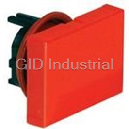
Switch Access Push Button Switch Rectangular Button AB6H-BK1-B
Switch Access Push Button Switch Rectangular Button AB6H-BK1-G
Switch Access Push Button Switch Rectangular Button AB6H-BK1-R
Switch Access Push Button Switch Rectangular Button AB6H-BK1-S
Switch Access Push Button Switch Rectangular Button AB6H-BK1-W
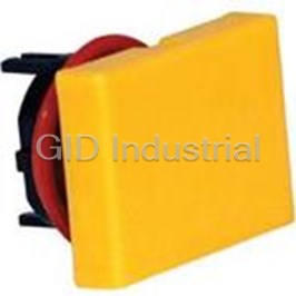
Switch Access Push Button Switch Rectangular Button AB6H-BK1-Y
Request a Quote

The quote request has been received
Close

Facing challenges or have inquiries? Feel free to contact us!
Call Us +1-469-283-2440
What they say about us
FANTASTIC RESOURCE
One of our top priorities is maintaining our business with precision, and we are constantly looking for affiliates that can help us achieve our goal. With the aid of GID Industrial, our obsolete product management has never been more efficient. They have been a great resource to our company, and have quickly become a go-to supplier on our list!
Bucher Emhart Glass
EXCELLENT SERVICE
With our strict fundamentals and high expectations, we were surprised when we came across GID Industrial and their competitive pricing. When we approached them with our issue, they were incredibly confident in being able to provide us with a seamless solution at the best price for us. GID Industrial quickly understood our needs and provided us with excellent service, as well as fully tested product to ensure what we received would be the right fit for our company.
Fuji
HARD TO FIND A BETTER PROVIDER
Our company provides services to aid in the manufacture of technological products, such as semiconductors and flat panel displays, and often searching for distributors of obsolete product we require can waste time and money. Finding GID Industrial proved to be a great asset to our company, with cost effective solutions and superior knowledge on all of their materials, it’d be hard to find a better provider of obsolete or hard to find products.
Applied Materials
CONSISTENTLY DELIVERS QUALITY SOLUTIONS
Over the years, the equipment used in our company becomes discontinued, but they’re still of great use to us and our customers. Once these products are no longer available through the manufacturer, finding a reliable, quick supplier is a necessity, and luckily for us, GID Industrial has provided the most trustworthy, quality solutions to our obsolete component needs.
Nidec Vamco
TERRIFIC RESOURCE
This company has been a terrific help to us (I work for Trican Well Service) in sourcing the Micron Ram Memory we needed for our Siemens computers. Great service! And great pricing! I know when the product is shipping and when it will arrive, all the way through the ordering process.
Trican Well Service
GO TO SOURCE
When I can't find an obsolete part, I first call GID and they'll come up with my parts every time. Great customer service and follow up as well. Scott emails me from time to time to touch base and see if we're having trouble finding something.....which is often with our 25 yr old equipment.
ConAgra Foods