

 Manufacturers
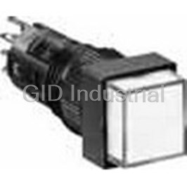
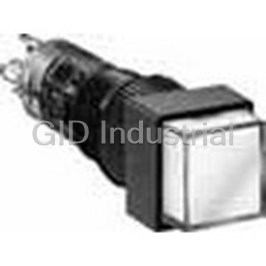
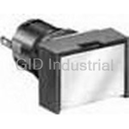
IDEC CORPORATION AL2Q-P1P-R
Description
Switch Indicators 1.7VDC 20mA LED Square Solder Panel Mount with Threads
AL2Q-P1P-R
Part Number
AL2Q-P1P-R
Price
Request Quote
Manufacturer
IDEC CORPORATION
Lead Time
Request Quote
Category
Optoelectronics and Displays » Switch Indicators
Specifications
Manufacturer
IDEC Corporation
Manufacturers Part #
AL2Q-P1P-R
Sub-Categories
Switch Indicators
Factory Pack Quantity
1
Datasheet

Extracted Text
ş12 A2 Series Miniature Control Units Short 22-mm-long body miniature control unit series with bright LED illumination face and snap-action switching. • Available in enclosed (IP40) and waterproof (IP65), and oiltight types. • 12-mm mounting holes • All series have terminals on the same plane. • UL recognized, CSA certiŢed Contact Ratings (Contact Block) SpeciŢcations Rated Insulation Voltage 250V Operating Temperature –25 to +55°C (no freezing) Rated Thermal Current 3A Storage Temperature –30 to +80° Operating Voltage (AC/DC) 24V 110V 220V Operating Humidity 45 to 85% RH (no condensation) Contact Resistance 50 mΩ maximum (initial value) Resistive Load – 1.0A 0.5A AC 50/60 Hz Insulation Resistance 100 MΩ minimum (500V DC megger) Inductive Load – 0.7A 0.5A Between live and dead metal parts: Resistive Load 1.0A 0.2A – DC 2,000V AC, 1 minute Inductive Load 0.7A 0.1A – Between terminals of different poles: 2,000V AC, 1 minute Contact Material Silver Switch Unit Between terminals of the same pole: Dielectric • Minimum applicable load: 5V AC/DC, 3 mA 1,000V AC, 1 minute Strength (applicable range may vary with operating conditions and load types) Between contact and lamp terminals: 1,500V AC, 1 minute Illumination Between live part and ground: Weight Unit 2,000V AC, 1 minute AL2M-M11: 4g Operating extremes: Vibration Resistance 5 to 55 Hz, amplitude 0.75 mm Weight (approx.) AL2M-P1: 4g 2 Damage limits: 500 m/s (50G) AB2M-M1: 4g Shock Resistance 2 Operating extremes: 200 m/s (20G) Mechanical Durability Momentary: 200,000 operations (minimum operations) Maintained: 100,000 operations Momentary: 100,000 operations Electrical Durability Maintained: 50,000 operations (minimum operations) (Switching frequency 1200 operations/h) Enclosed (IP40) Degree of Protection Waterproof, dust-tight (IP65) LED Lamp Ratings (LAD-S Type) Type No. LAD-SA LAD-SG LAD-SR LAD-SY Lamp Base Exclusive for A series control units Forward Current (If) 20 mA Forward Voltage (Vf) (nominal) 2.2V 2.1V 1.7V 2.2V Reverse Voltage (Vr) 4V Illumination Color A G R Y LED Lamp Color Amber Clear Yellow Diffused Red Clear Yellow Clear Applicable Lens Color Amber Green Red Yellow and White Base Plastic Color Red LED Lamp Life (reference value) Approx. 50,000 hours (The illuminance reduces to 50% the initial intensity when used on complete DC.) Operating Voltage & External 5V DC: 150Ω, 1/2W Current-limiting Resistor 6V DC: 200Ω, 1/2W (recommended value) 12V DC: 510Ω, 1W (Note) 24V DC: 1.1 kΩ, 1W Internal Circuit (+) (–) Note: When LED lamps are used on voltages other than the above, external resistor value R is determined by the following formula: R = (operating voltage – Vf) / If • LED lamps do not have a current-limiting resistor, and external resistors of recommended values for each voltage must be provided. Connect a current-limiting resistor in series, otherwise LED lamps will be damaged. Because no protection diode (+) (–) is contained, ensure the correct polarity is observed. Current Lamp Lamp Limiting Terminal (+) Terminal (–) Resistor (06/11/10) 24 ş12 A2 Series Miniature Control Units AL2 LED Illuminated Pushbuttons & Pilot Lights Type No. LED Lamp Type No., Rated Operation ➁ Lens Color Shape Contact Current Type Code IP40 IP65 (External Resistor Recommended Value) Round SPDT AL2M-M11➁ AL2M-M11P➁ AL2M Momentary DPDT AL2M-M21➁ AL2M-M21P➁ SPDT AL2M-A11➁ AL2M-A11P➁ Maintained DPDT AL2M-A21➁ AL2M-A21P➁ Marking plate size: ş10 mm Engraving area: ş8.2 mm Pilot Light — AL2M-P1➁ AL2M-P1P➁ (Depth: 0.5 mm max.) A: LAD-SA Square SPDT AL2Q-M11➁ AL2Q-M11P➁ AL2Q G: LAD-SG Momentary Specify a color R: LAD-SR code in place of DPDT AL2Q-M21➁ AL2Q-M21P➁ W/Y: LAD-SY ➁ in the Type No. A: amber SPDT AL2Q-A11➁ AL2Q-A11P➁ Rated Current: 20 mA G: green Maintained R: red DPDT AL2Q-A21➁ AL2Q-A21P➁ 5V DC: 150Ω, 1/2W W: white � Marking plate size: 10 mm 6V DC: 200Ω, 1/2W Y: yellow Engraving area: �8.2 mm Pilot Light — AL2Q-P1➁ AL2Q-P1P➁ 12V DC: 510Ω, 1W (Depth: 0.5 mm max.) 24V DC: 1.1 kΩ, 1W Rectangular SPDT AL2H-M11➁ AL2H-M11P➁ AL2H Momentary DPDT AL2H-M21➁ AL2H-M21P➁ SPDT AL2H-A11➁ AL2H-A11P➁ Maintained DPDT AL2H-A21➁ AL2H-A21P➁ Marking plate size: 10 × 14 mm Engraving area: 8.2 × 12.2 mm Pilot Light — AL2H-P1➁ AL2H-P1P➁ (Depth: 0.5 mm max.) • LED lamps do not have a current-limiting resistor. Connect a current-limiting resistor in series, otherwise LED lamps will be damaged. • External current-limiting resistor is not necessary when an optional socket with built-in resistor is used (see page 27). LED Lamp • AP2M series pilot lights (round bezel only) with built-in current-limiting resistors are also available. Internal Circuit (+) (–) Dimensions Panel Thickness 0.5 to 6 Rubber Gasket RectangularR Squareound Locking Ring (TOP) (TOP)(TOP) Terminal Width 1.8×0.4t 55.5 0.6 0.6 5.5 722 9 18 c14 ø14 9 Terminal Arrangement Mounting Hole Layout • • • • Round/Square Units • • • • Rectangular Units Lamp Terminal (+) +0.2 +0.2 (TOP) 0 ø12 0 ø12 NC1NC2 SPDT has NC1, Note: Determine mounting NO1, and C1 only. centers to ensure NO1 NO2 easy operation. C1 C2 Lamp Terminal (–) 18 min. 14 min. All dimensions in mm. (06/11/10) 25 9.2 2.8 2.8 14 min. 14 ø14 14 min. ş12 A2 Series Miniature Control Units AB2 Pushbuttons Type No. Operation Shape Button Type Contact Color Code ➀➁ Type IP40 IP65 Round B: black SPDT AB2M-M1➀ AB2M-M1P➀ AB2M Momentary G: green DPDT AB2M-M2➀ AB2M-M2P➀ R: red Button S: blue SPDT AB2M-A1➀ AB2M-A1P➀ W: white Maintained DPDT AB2M-A2➀ AB2M-A2P➀ Y: yellow SPDT AB2M-M1L➁ AB2M-M1PL➁ A: amber Momentary G: green DPDT AB2M-M2L➁ AB2M-M2PL➁ Illumination Lens R: red SPDT AB2M-A1L➁ AB2M-A1PL➁ W: white Maintained Y: yellow DPDT AB2M-A2L➁ AB2M-A2PL➁ Square B: black SPDT AB2Q-M1➀ AB2Q-M1P➀ Momentary AB2Q G: green DPDT AB2Q-M2➀ AB2Q-M2P➀ R: red Button S: blue SPDT AB2Q-A1➀ AB2Q-A1P➀ W: white Maintained DPDT AB2Q-A2➀ AB2Q-A2P➀ Y: yellow SPDT AB2Q-M1L➁ AB2Q-M1PL➁ A: amber Momentary G: green DPDT AB2Q-M2L➁ AB2Q-M2PL➁ Illumination Lens R: red SPDT AB2Q-A1L➁ AB2Q-A1PL➁ W: white Maintained Y: yellow DPDT AB2Q-A2L➁ AB2Q-A2PL➁ Rectangular B: black SPDT AB2H-M1➀ AB2H-M1P➀ Momentary AB2H G: green DPDT AB2H-M2➀ AB2H-M2P➀ R: red Button S: blue SPDT AB2H-A1➀ AB2H-A1P➀ Maintained W: white DPDT AB2H-A2➀ AB2H-A2P➀ Y: yellow SPDT AB2H-M1L➁ AB2H-M1PL➁ A: amber Momentary G: green DPDT AB2H-M2L➁ AB2H-M2PL➁ Illumination Lens R: red SPDT AB2H-A1L➁ AB2H-A1PL➁ W: white Maintained Y: yellow DPDT AB2H-A2L➁ AB2H-A2PL➁ • Specify a color code in place of ➀ or ➁ in the Type No. Dimensions Panel Thickness 0.5 to 6 Rubber Gasket Locking Ring RectangularR Squareound ( ) ()( ) TOP TOP TOP 5 0.6 0.6 5.5 5.5 22 9 18 9 c14 ø14 Terminal Arrangement Mounting Hole Layout • • • • Round/Square Units • • • • Rectangular Units (TOP) +0.2 +0.2 NC1NC2 ø12 0 ø12 0 NO1 NO2 C1 C2 SPDT has NC1, NO1, and C1 only. 18 min. 14 min. Note: Determine mounting centers to ensure easy operation. All dimensions in mm. (06/11/10) 26 2.8 2.8 14 min. 14 14 min. ş12 A2 Series Miniature Control Units Accessories Ordering Package Shape Material Type No. Dimensions (mm) Type No. Quantity Locking Ring Wrench • Used to tighten the locking ring when installing the A2 control units into a ş14 Metal panel. MT-002 MT-002 1 (nickel-plated brass) • Tighten the locking ring to a torque of 60 0.78 N·m maximum. Lens Removal Tool Stainless Steel MT-101 MT-101 1 • Used to remove lens and button. 60 Lamp Holder Tool Rubber OR-66 OR-66 1 • Used to remove and install LED lamps. 70 Switch Guard • Degree of protection: For round/ IP40 AL-K2 AL-K2 1 square Unit • Used to protect 90° open pushbuttons from inadvertent operation. (remains For rectangular AL-KH2 AL-KH2 1 • See page 28 for 90° open) unit dimensions. Socket Solder Terminal AL-C2 AL-C2 1 • Snaps on the rear of the A2 series control units. (see page 28 for dimensions) PC Board Terminal AL-C2V AL-C2V 1 Socket with Built-in Resistor 5V DC AL-C21 AL-C21 1 Blue • A current limiting resistor is contained, eliminating the 6V DC AL-C22 AL-C22 1 Green need for external resistors. Solder • When using the socket with a Terminal 12V DC AL-C23 AL-C23 1 Yellow built-in resistor, make sure that the continuous current is 24V DC AL-C24 AL-C24 1 Red 1A maximum and the operating temperature is –25 to +40°C. In collective 5V DC AL-C21V AL-C21V 1 Blue mounting, keep center-to center-spacing of 20 mm or 6V DC AL-C22V AL-C22V 1 Green PC Board more between adjacent units in consideration of built-in Terminal 12V DC AL-C23V AL-C23V 1 Yellow resistor heating. • See page 28 for dimensions. 24V DC AL-C24V AL-C24V 1 Red Terminal Cover • When wiring the terminals, insert the lead wires into the terminal cover holes before soldering. Nylon AL-V2 AL-V2PN10 10 • Terminal cover is not attached and must be ordered separately. Dust Cover • When mounting the control units with For round units AL-D2 AL-D2 1 the dust covers installed, refer to mounting hole layout on page 29. • Operating temperature: –10 to +55°C For square units AL-DQ2 AL-DQ2 1 • Material Front part: Elastomer (transparent) Rear part: Polypropylene (black) For rectangular units AL-DH2 AL-DH2 1 • See page 29 for dimensions and mounting hole layout. Mounting Hole Plug Nitryl rubber (black) AL-B2 AL-B2PN05 5 • Degree of protection: IP65 LED Lamp LAD-SA 1 Illumination color: amber LAD-SA Amber LED color: amber clear LAD-SAPN10 10 LAD-SG 1 Illumination color: green LAD-SG Green LED color: yellow diffused LAD-SGPN10 10 Current-limiting LAD-SR 1 resistor is not Illumination color: red LAD-SR Red LED color: clear red LAD-SRPN10 10 contained. 5.3 LAD-SY 1 9.0 White/ Illumination color: yellow LAD-SY LED color: yellow clear Yellow All dimensions in mm. LAD-SYPN10 10 (06/11/10) 27 ø4.0 Lens color Socket Bottom Color ş12 A2 Series Miniature Control Units Maintenance Parts Package Shape SpeciŢcation Type No. Ordering Type No. Color Code ➀➁ Quantity Marking Plate Round AL2M-W AL2M-WPN05 Square AL2Q-W AL2Q-WPN05 5 • White Rectangular AL2H-W AL2H-WPN05 Lens Unit Round AL2M-LK1-➁ AL2M-LK1-➁PN02 For IP40 units Square AL2Q-LK1-➁ AL2Q-LK1-➁PN02 2 Rectangular AL2H-LK1-➁ AL2H-LK1-➁PN02 • Specify a color code in place of ➁ in the Type No. Round AL2M-LK2-➁ AL2M-LK2-➁ For IP65 illumi- A (amber) nated pushbut- Square AL2Q-LK2-➁ AL2Q-LK2-➁ G (green) tons R (red) Rectangular AL2H-LK2-➁ AL2H-LK2-➁ W (white) 1 Y (yellow) Round AL2M-LK3-➁ AL2M-LK3-➁ For IP65 pilot Square AL2Q-LK3-➁ AL2Q-LK3-➁ lights Rectangular AL2H-LK3-➁ AL2H-LK3-➁ Button Unit Round AB2M-BK1-➀ AB2M-BK1-➀PN02 • Specify a color code in place of For IP40 Square AB2Q-BK1-➀ AB2Q-BK1-➀PN02 2 ➀ in the Type No. pushbuttons B (black) Rectangular AB2H-BK1-➀ AB2H-BK1-➀PN02 G (green) R (red) Round AB2M-BK2-➀ AB2M-BK2-➀ S (blue) For IP65 W (white) Square AB2Q-BK2-➀ AB2Q-BK2-➀ 1 pushbuttons Y (yellow) Rectangular AB2H-BK2-➀ AB2H-BK2-➀ Dimensions • Switch Guard For Round/Square Units (AL-K2) For Rectangular Units (AL-KH2) Panel Thickness Panel Thickness 26.5 0.5 to 5 26.5 0.5 to 5 14 18 12.5 Rubber Gasket 12.5 Rubber Gasket 15 min. 19 min. � � � � • Socket (AL-C2, AL-C2V, AL-C2 ) Terminal Arrangement Terminal 0.8 × 0.3t Lamp Terminal (+) 33 1 6 33 1 6 (TOP) NC1 NC2 NO1 NO2 C1 C2 17 6.5 13 17 4.5 +0.2 Lamp Terminal (–) 8-1.0 Hole 0 s Solder Terminal Type PC Board Terminal Panel Cut-out ( ) AL-C2 (AL-C2V) Bottom View 36 1 6 36 1 6 5.5 13 3.5 +0.2 20 7 8-1.0 Hole 0 s 20 5 Solder Terminal Type with Built-in Resistor PC Board Terminal Type Panel Cut-out ( c) AL-C2 with Built-in Resistor (AL-C2 c V) Bottom View All dimensions in mm. (06/11/10) 28 19.5 8.5 11 22.5 min. 6.5 7.3 10.5 10.5 2.8 2.8 2.8 2.8 19.5 8.5 11 10.5 6.5 7.3 2.8 2.8 22.5 min. 10.2 5.3 4.9 2.8 2.8 ş12 A2 Series Miniature Control Units Dimensions • Terminal Cover (AL-V2) 17.3 Note: When wiring the terminals, insert the lead wires into the terminal cover holes before soldering. 33.5 • Dust Cover For Round Units For Square Units For Rectangular Units Mounting Hole Centers (AL-D2) (AL-DQ2) (AL-DH2) (Round Units, Square Units) c 20 ø20 24 ø12 20 min. (Rectangular Units) Waterproof Gasket Waterproof Gasket for Dust Cover Waterproof Gasket for Dust Cover for Dust Cover ø12 24 min. Note: Determine mounting centers to ensure easy operation. All dimensions in mm. (06/11/10) 29 0.3 12 6.5 0.3 12 6.5 ø12.8 0.3 12 6.5 20 20 min. 20 min. ş12 A2 Series Miniature Control Units Safety Precautions • Turn off the power to A series control units before starting • For wiring, use wires of a proper gauge to meet the voltage and installation, removal, wiring, maintenance, and inspection of the current requirements. Failure to tighten terminal screws may control units. Failure to turn power off may cause electrical shocks cause overheating and create a Ţre hazard. or Ţre hazard. • To avoid burning your hand, use the lamp holder tool when replacing lamps. Operating Instructions Replacement of Lens and Marking Plate Wiring • Removal Solder the terminal at 350°C within 3 seconds using a 60W soldering iron. Sn-Ag-Cu type is recommended when using lead- Remove the lens assembly (color lens, marking plate, lens holder, free solder. When soldering, do not touch the control unit with the and spring) by holding the color lens recesses with the Lens soldering iron. Also ensure that no tensile force is applied to the Removal Tool (MT-101) and pulling it out. Remove the marking plate terminal. Do not bend the terminal or apply excessive force to the by disengaging the latches between the color lens and lens holder. terminal. The marking plate must be engraved on the front side as shown Use non-corrosive rosin ţux. below. Latches Installing the Socket Install the socket on the control unit with the TOP markings on the control unit and the socket placed in the same direction. Operating Voltage of LED Lamps Engraving Area The operating voltage is measured at complete DC. When using a Color Lens Marking Lens Holder pulsating voltage such as a full-wave rectiŢcation voltage, keep Plate peak currents within the forward current If. Peak currents exceeding • Installation the If may shorten the LED lamp life. Place the marking plate on the lens holder in the correct direction, and press the color lens onto the lens holder to engage the latches. Other Notes Put the spring on the lens holder and insert the lens holder into the • Close Proximity Mounting housing in the correct direction. When mounting pilot lights or illuminated pushbuttons collectively or • Installing Non-illuminated Button lighting them continuously, heat may cause the ambient Non-illuminated pushbuttons contain a marking plate like temperature to rise above the rated operating temperature. When illuminated units. Be sure to install the marking plate when replacing the mounting panel is not made of metal or when the control units the button. are mounted in an enclosed panel, provide for ventilation or lower the operating voltage. Replacing the LED Lamp • Replacement of Buttons (Illuminated/Non-illuminated) Do not replace buttons of maintained action units while the button is • Removal in the locked position. Replacing the button in the locked position Use the lamp holder tool (OR-66) to remove lamps. Do not use may damage the internal mechanism. Be sure to release the button pliers. before replacing. • Installation • Operating and Storage Environment Use the lamp holder tool (OR-66) to install lamps. Note the correct 1. Make sure that the operating/storage temperature and humidity side of the tool for removal or installation. are within the ratings. Lamp Holder Tool 2. Do not use enclosed type units (IP40) in an environment subject OR-66 (ø8, ø10, ø12 series) to oil, water or dust accumulation. In such an area, use the waterproof/oiltight units (IP65). • Microswitch Contacts For removing lamps For installing lamps Do not connect NO and NC contacts of the microswitch to different voltages or different power sources to prevent a dead short-circuit. Panel Mounting • IP65 Type Units When mounting the control units onto a panel, use the optional IP65 type units are evaluated by conventional cutting and cooling locking ring wrench (MT-002) to tighten the locking ring. Do not use oils, and can not be used with some special oils. Contact IDEC for pliers. Tightening torque must not exceed 0.78 N·m. Excessive resistance against special oils. tightening will damage the locking ring. (06/11/10) 30 A1 Series Miniature Control Units ş10 Short 22-mm-long body miniature control unit series with LED illumination face and snap-action switching. • Bright and clear LED illumination. • 10-mm mounting holes • All series have terminals on the same plane. • UL recognized, CSA certiŢed Contact Ratings (Contact Block) SpeciŢcations Operating Temperature –25 to +55°C (no freezing) Rated Insulation Voltage 250V Operating Humidity 45 to 85% RH (no condensation) Rated Thermal Current 3A Contact Resistance 50 mΩ maximum (initial value) Operating Voltage (AC/DC) 24V 110V 220V Insulation Resistance 100 MΩ minimum (500V DC megger) Resistive Load – 1.0A 0.5A AC 50/60 Hz Between live and dead metal parts: Inductive Load – 0.7A 0.5A 2,000V AC, 1 minute Resistive Load 1.0A 0.2A – Between terminals of different poles: DC 2,000V AC, 1 minute Inductive Load 0.7A 0.1A – Switch Unit Between terminals of the same pole: Dielectric Contact Material Silver 1,000V AC, 1 minute Strength Between contact and lamp terminals: • Minimum applicable load: 5V AC/DC, 3 mA 1,500V AC, 1 minute (applicable range may vary with operating conditions and load types) Illumination Between live part and ground: Unit 2,000V AC, 1 minute Weight Operating extremes: Vibration Resistance AL1M-M11: 3g 5 to 55 Hz, amplitude 0.75 mm 2 Damage limits: 500 m/s (50G) Weight (approx.) AL1M-P1: 3g Shock Resistance 2 Operating extremes: 200 m/s (20G) AB1M-M1: 3g Mechanical Durability Momentary: 200,000 operations (minimum operations) Maintained: 100,000 operations Momentary: 100,000 operations Electrical Durability Maintained: 50,000 operations (minimum operations) (Switching frequency 1200 operations/h) Degree of Protection Enclosed (IP40) LED Lamp Ratings (LAD-S Type) Type No. LAD-SA LAD-SG LAD-SR LAD-SY Lamp Base Exclusive for A series control units Forward Current (If) 20 mA Forward Voltage (Vf) (nominal) 2.2V 2.1V 1.7V 2.2V Reverse Voltage (Vr) 4V Illumination Color A G R Y LED Lamp Color Amber Clear Yellow Diffused Red Clear Yellow Clear Applicable Lens Color Amber Green Red Yellow and White Base Plastic Color Red LED Lamp Life (reference value) Approx. 50,000 hours (The illuminance reduces to 50% the initial intensity when used on complete DC.) Operating Voltage & External 5V DC: 150Ω, 1/2W Current-limiting Resistor 6V DC: 200Ω, 1/2W (recommended value) 12V DC: 510Ω, 1W (Note) 24V DC: 1.1 kΩ, 1W Internal Circuit (+) (–) Note: When LED lamps are used on voltages other than the above, external resistor value R is determined by the following formula: R = (operating voltage – Vf) / If • LED lamps do not have a current-limiting resistor, and external resistors of recommended values for each voltage must be provided. Connect a current-limiting resistor in series, otherwise LED lamps will be damaged. Because (+) (–) no protection diode is contained, ensure the correct polarity is observed. Current Lamp Lamp Limiting Terminal (+) Terminal (–) Resistor (06/11/10) 31 ş10 A1 Series Miniature Control Units AL1 LED Illuminated Pushbuttons & Pilot Lights Type No. LED Lamp Operation Type No., Rated Current Shape Contact ➁ Lens Color Code Type IP40 (External Resistor Recommended Value) Round AL1M Momentary SPDT AL1M-M11➁ Maintained SPDT AL1M-A11➁ Marking plate size: ş8.5 mm Pilot Light — AL1M-P1➁ Engraving area: ş7 mm (Depth: 0.5 mm max.) A: LAD-SA Square G: LAD-SG AL1Q Specify a color code in Momentary SPDT AL1Q-M11➁ R: LAD-SR place of ➁ in the Type W/Y: LAD-SY No. A: amber Rated Current: 20 mA Maintained SPDT AL1Q-A11➁ G: green R: red 5V DC: 150Ω, 1/2W W: white � Marking plate size: 8.5 mm 6V DC: 200Ω, 1/2W Y: yellow Pilot Light — AL1Q-P1➁ � Engraving area: 7 mm 12V DC: 510Ω, 1W (Depth: 0.5 mm max.) 24V DC: 1.1 kΩ, 1W Rectangular AL1H Momentary SPDT AL1H-M11➁ Maintained SPDT AL1H-A11➁ Marking plate size: 8.5 × 12.5 mm Engraving area: 7 × 11 mm Pilot Light — AL1H-P1➁ (Depth: 0.5 mm max.) • LED lamps do not have a current-limiting resistor. Connect a current-limiting resistor in series, LED Lamp otherwise LED lamps will be damaged. Internal Circuit (+) (–) • AP1M series pilot lights (round bezel only) with built-in current-limiting resistor are also available. Dimensions Panel Thickness 0.5 to 6 Locking Ring Rectangular Square Round ( ) ( ) ( ) TOP TOP TOP Terminal Width 1.8×0.4t ø12 c 6 5.5 16 12 ø12 5.5 22 9 (bottom view) Terminal Arrangement Mounting Hole Layout • • • • Round/Square Units • • • • Rectangular Units (TOP) +0.2 +0.2 ø10 ø10 0 0 NC NO COM Lamp Lamp Terminal (+) Terminal (–) 12 min. 16 min. Note: Determine mounting centers to ensure easy operation. All dimensions in mm. (06/11/10) 32 2.8 2.8 12 min. 12 12 min. ş10 A1 Series Miniature Control Units AB1 Pushbuttons Type No. Shape Button Type Operation Type Contact Color Code ➀➁ IP40 Round Bblack Momentary SPDT AB1M-M1➀ G: green AB1M R: red Button S: blue W: white Maintained SPDT AB1M-A1➀ Y: yellow A: amber Momentary SPDT AB1M-M1L➁ G: green Illumination Lens R: red W: white Maintained SPDT AB1M-A1L➁ Y: yellow Square Bblack Momentary SPDT AB1Q-M1➀ G: green AB1Q R: red Button S: blue W: white Maintained SPDT AB1Q-A1➀ Y: yellow A: amber Momentary SPDT AB1Q-M1L➁ G: green Illumination Lens R: red W: white Maintained SPDT AB1Q-A1L➁ Y: yellow Rectangular Bblack Momentary SPDT AB1H-M1➀ G: green AB1H R: red Button S: blue Maintained SPDT AB1H-A1➀ W: white Y: yellow A: amber Momentary SPDT AB1H-M1L➁ G: green Illumination Lens R: red W: white Maintained SPDT AB1H-A1L➁ Y: yellow • Specify a color code in place of ➀ or ➁ in the Type No. Dimensions Panel Thickness 0.5 to 6 Locking Ring Rectangular Square Round (TOP) (TOP) (TOP) Terminal Width 1.8×0.4t 6 5.5 16 c12 ø12 5.5 22 9 (bottom view) Terminal Arrangement Mounting Hole Layout • • • • Round/Square Units • • • • Rectangular Units (TOP) +0.2 +0.2 ø10 ø10 0 0 NC NO COM 12 min. 16 min. Note: Determine mounting centers to ensure easy operation. All dimensions in mm. (06/11/10) 33 2.8 2.8 12 12 min. 12 min. ş10 A1 Series Miniature Control Units Accessories Ordering Package Shape Material Type No. Dimensions (mm) Type No. Quantity Locking Ring Wrench • Used to tighten the locking ring when installing the A1 control units into a ş12 Metal panel. MT-003 MT-003 1 (nickel-plated brass) • Tighten the locking ring to a torque of 60 0.29 N·m maximum. Lens Removal Tool Stainless Steel MT-101 MT-101 1 • Used to remove lens and button. 60 Lamp Holder Tool Rubber OR-66 OR-66 1 • Used to remove and install LED lamps. 70 Switch Guard • Used to protect For round/ AL-K1 AL-K1 1 pushbuttons from square Unit inadvertent operation. 90° open • See page 35 for For rectangular (remains AL-KH1 AL-KH1 1 dimensions. unit 90° open) Socket Solder Terminal AL-C1 AL-C1 1 • Snaps on the rear of the A1 series control units. (see page 35 for dimensions) PC Board Terminal AL-C1V AL-C1V 1 Terminal Cover • When wiring the terminals, insert the lead wires into the terminal cover holes before soldering. Nylon AL-V1 AL-V1PN10 10 • Terminal cover is not attached and must be ordered separately. Mounting Hole Plug • Degree of protection: IP65 ø12 Nitryl rubber (black) AL-B1 AL-B1PN05 5 LED Lamp LAD-SA 1 Illumination color: amber LAD-SA Amber LED color: amber clear LAD-SAPN10 10 LAD-SG 1 Illumination color: green LAD-SG Green LED color: yellow diffused LAD-SGPN10 10 Current-limiting LAD-SR 1 resistor is not Illumination color: red LAD-SR Red LED color: clear red contained. LAD-SRPN10 10 5.3 9.0 LAD-SY 1 White/ Illumination color: yellow LAD-SY LED color: yellow clear Yellow All dimensions in mm. LAD-SYPN10 10 (06/11/10) 34 ø4.0 Lens color 4.4 2 ş10 A1 Series Miniature Control Units Maintenance Parts Package Shape Type No. Ordering Type No. Color Code ➀➁ Quantity Marking Plate Round AL1M-W AL1M-WPN05 Square AL1Q-W AL1Q-WPN05 5 •White Rectangular AL1H-W AL1H-WPN05 Lens Unit Round AL1M-LK1-➁ AL1M-LK1-➁PN02 Specify a color code in place of ➁ in the Type No. Square AL1Q-LK1-➁ AL1Q-LK1-➁PN02 A (amber), G (green), R (red) W (white), Y (yellow) Rectangular AL1H-LK1-➁ AL1H-LK1-➁PN02 2 Button Unit Round AB1M-BK1-➀ AB1M-BK1-➀PN02 Specify a color code in place of ➀ in the Type No. Square AB1Q-BK1-➀ AB1Q-BK1-➀PN02 B (black), G (green), R (red) S (blue), W (white), Y (yellow) Rectangular AB1H-BK1-➀ AB1H-BK1-➀PN02 Dimensions • Switch Guard For Round/Square Units (AL-K1) For Rectangular Units (AL-KH1) Panel Thickness 12 16 24.5 0.5 to 5 12.5 13 min. 17 min. • Socket (AL-C1, AL-C1V) Terminal 0.8 × 0.3t Terminal Arrangement 33 7.3 33 7.3 (TOP) NC NO COM Lamp Lamp 17 5 11 17 3 +0.2 Terminal (+) Terminal (–) 5-1.0 Hole 0 s ( ) Bottom View Solder Terminal PC Board Terminal (PC Board Terminal ( ) ( ) Mounting Hole Layout) AL-C1 AL-C1V • Terminal Cover 17.3 Note: When wiring the terminals, insert the lead wires into the terminal cover holes before soldering. 33.5 All dimensions in mm. (06/11/10) 35 17.5 7.5 10 20.5 min. ø10.8 17.5 7.5 10 2.8 2.8 20.5 min. 2.8 2.8 ş10 A1 Series Miniature Control Units Safety Precautions • Turn off the power to A series control units before starting • For wiring, use wires of a proper gauge to meet the voltage and installation, removal, wiring, maintenance, and inspection of the current requirements. Failure to tighten terminal screws may control units. Failure to turn power off may cause electrical shocks cause overheating and create a Ţre hazard. or Ţre hazard. • To avoid burning your hand, use the lamp holder tool when replacing lamps. Operating Instructions Replacement of Lens and Marking Plate Wiring • Removal Solder the terminal at 350°C within 3 seconds using a 60W soldering iron. Sn-Ag-Cu type is recommended when using lead- Remove the lens assembly (color lens, marking plate, lens holder, free solder. When soldering, do not touch the control unit with the and spring) by holding the color lens recesses with the Lens soldering iron. Also ensure that no tensile force is applied to the Removal Tool (MT-101) and pulling it out. Remove the marking plate terminal. Do not bend the terminal or apply excessive force to the by disengaging the latches between the color lens and lens holder. terminal. The marking plate must be engraved on the front side as shown Use non-corrosive rosin ţux. below. Latches Installing the Socket Install the socket on the control unit with the TOP markings on the control unit and the socket placed in the same direction. Engraving Spring Area Spring Operating Voltage of LED Lamps Color lens Marking Lens Retaining Plate Holder Groove The operating voltage is measured at complete DC. When using a pulsating voltage such as a full-wave rectiŢcation voltage, keep Note: Make sure that the spring is inserted in the correct peak currents within the forward current If. Peak currents exceeding direction. The base of spring must Ţt the groove in the the If may shorten the LED lamp life. holder. • Installation Other Notes Place the marking plate on the lens holder in the correct direction, • Close Proximity Mounting and press the color lens onto the lens holder to engage the latches. When mounting pilot lights or illuminated pushbuttons collectively or Put the spring on the lens holder and insert the lens holder into the lighting them continuously, heat may cause the ambient housing in the correct direction. temperature to rise above the rated operating temperature. When • Installing Non-illuminated Button the mounting panel is not made of metal or when the control units Non-illuminated pushbuttons contain a marking plate like illumi- are mounted in an enclosed panel, provide for ventilation or lower nated units. Be sure to install the marking plate when replacing the the operating voltage. button. • Replacement of Buttons (Illuminated/Non-illuminated) Do not replace buttons of maintained action units while the button is Replacing the LED Lamp in the locked position. Replacing the button in the locked position may damage the internal mechanism. Be sure to release the button • Removal before replacing. Use the lamp holder tool (OR-66) to remove lamps. Do not use • Operating and Storage Environment pliers. 1. Make sure that the operating/storage temperature and humidity • Installation are within the ratings. Use the lamp holder tool (OR-66) to install lamps. Note the correct 2. Do not use enclosed type units in an environment subject to oil, side of the tool for removal or installation. water or dust accumulation. Lamp Holder Tool • Microswitch Contacts OR-66 (ø8, ø10, ø12 series) Do not connect NO and NC contacts of the microswitch to different voltages or different power sources to prevent a dead short-circuit. For removing lamps For installing lamps Panel Mounting When mounting the control units into a panel, use the optional locking ring wrench (MT-003) to tighten the locking ring. Do not use pliers. Tightening torque must not exceed 0.29 N·m. Excessive tightening will damage the locking ring. (06/11/10) 36 ş8 A8 Series Miniature Control Units Short 22-mm-long body miniature control unit series with LED illumination face and snap-action switching. • Bright and clear LED illumination. • 8-mm mounting holes • All series have terminals on the same plane. • UL recognized, CSA certiŢed Contact Ratings (Contact Block) SpeciŢcations Operating Temperature –25 to +55°C (no freezing) Rated Insulation Voltage 250V Operating Humidity 45 to 85% RH (no condensation) Rated Thermal Current 3A Contact Resistance 50 mΩ maximum (initial value) Operating Voltage (AC/DC) 24V 110V 220V Insulation Resistance 100 MΩ minimum (500V DC megger) Resistive Load – 1.0A 0.5A Between live and dead metal parts AC 50/60 Hz 2,000V AC, 1 minute Inductive Load – 0.7A 0.5A Between terminals of different poles: Resistive Load 1.0A 0.2A – 2,000V AC, 1 minute DC Switch Unit Between terminals of the same pole: Inductive Load 0.7A 0.1A – Dielectric 1,000V AC, 1 minute Strength Contact Material Silver Between contact and lamp terminals: 1,500V AC, 1 minute • Minimum applicable load: 5V AC/DC, 3 mA (applicable range may vary with operating conditions and load types) Illumination Between live part and ground: Unit 2,000V AC, 1 minute Operating extremes: Vibration Resistance Weight 5 to 55 Hz, amplitude 0.75 mm 2 AL8M-M11: 2g Damage limits: 500 m/s (50G) Shock Resistance 2 Operating extremes: 200 m/s (20G) Weight (approx.) AL8M-P1: 2g Mechanical Durability Momentary: 200,000 operations AB8M-M1: 2g (minimum operations) Maintained: 100,000 operations Momentary: 100,000 operations Electrical Durability Maintained: 50,000 operations (minimum operations) (Switching frequency 1200 operations/h) Degree of Protection Enclosed (IP40) LED Lamp Ratings (LAD-S Type) Type No. LAD-SA LAD-SG LAD-SR LAD-SY Lamp Base Exclusive for A series control units Forward Current (If) 20 mA Forward Voltage (Vf) (nominal) 2.2V 2.1V 1.7V 2.2V Reverse Voltage (Vr) 4V Illumination Color A G R Y LED Lamp Color Amber Clear Yellow Diffused Red Clear Yellow Clear Applicable Lens Color Amber Green Red Yellow and White Base Plastic Color Red LED Lamp Life (reference value) Approx. 50,000 hours (The illuminance reduces to 50% the initial intensity when used on complete DC.) Operating Voltage & External 5V DC: 150Ω, 1/2W Current-limiting Resistor 6V DC: 200Ω, 1/2W (recommended value) 12V DC: 510Ω, 1W (Note) 24V DC: 1.1 kΩ, 1W Internal Circuit (+) (–) Note: When LED lamps are used on voltages other than the above, external resistor value R is determined by the following formula: R = (operating voltage – Vf) / If • LED lamps do not have a current-limiting resistor, and external resistors of recommended values for each voltage must be provided. Connect a current-limiting resistor in series, otherwise LED lamps will be damaged. Because no protection (+) (–) diode is contained, ensure the correct polarity is observed. Current Lamp Lamp Limiting Terminal (+) Terminal (–) Resistor (06/11/10) 37 ş8 A8 Series Miniature Control Units AL8 LED Illuminated Pushbuttons & Pilot Lights Type No. LED Lamp Operation ➁ Lens Color Type No., Rated Current Shape Contact Type Code IP40 (External Resistor Recommended Value) Round AL8M Momentary SPDT AL8M-M11➁ Maintained SPDT AL8M-A11➁ Marking plate size: ş6 mm Pilot Light — AL8M-P1➁ Engraving area: ş4.5 mm (Depth: 0.5 mm max.) A: LAD-SA Square G: LAD-SG AL8Q Specify a color Momentary SPDT AL8Q-M11➁ R: LAD-SR code in place of ➁ W/Y: LAD-SY in the Type No. A: amber Maintained SPDT AL8Q-A11➁ Rated Current: 20 mA G: green R: red 5V DC: 150Ω, 1/2W W: white Marking plate size: �6 mm 6V DC: 200Ω, 1/2W Pilot Light — AL8Q-P1➁ Y: yellow � Engraving area: 4.5 mm 12V DC: 510Ω, 1W (Depth: 0.5 mm max.) 24V DC: 1.1 kΩ, 1W Rectangular AL8H Momentary SPDT AL8H-M11➁ Maintained SPDT AL8H-A11➁ Marking plate size: 6 × 9 mm Pilot Light — AL8H-P1➁ Engraving area: 4.5 × 7.5 mm (Depth: 0.5 mm max.) • LED lamps do not have a current-limiting resistor. Connect a current-limiting resistor in series, otherwise LED Lamp LED lamps will be damaged. Internal Circuit (+) (–) • AP8M series pilot lights (round bezel only) with built-in current-limiting resistor are also available. Dimensions Panel Thickness 0.5 to 6 Locking Ring Rectangular Square Round ( ) ( ) ( ) TOP TOP TOP Terminal Width 1.8 × 0.4t ø9 5 5.5 5.5 12 c 9 ø9 7 22 9 Terminal Arrangement Mounting Hole Layout • • • • Round/Square Units • • • • Rectangular Units (TOP) +0.2 +0.2 ø8 0 ø8 0 NC NO COM Lamp Lamp Terminal (+) Terminal (–) 12 min. 9 min. Note: Determine mounting centers to ensure easy operation. All dimensions in mm. (06/11/10) 38 2.5 2.5 9 min. 9 9 min. ş8 A8 Series Miniature Control Units AB8 Pushbuttons Type No. Shape Button Type Operation Type Contact Color Code ➀➁ IP40 Round Bblack Momentary SPDT AB8M-M1➀ AB8M G: green R: red Button S: blue W: white Maintained SPDT AB8M-A1➀ Y: yellow A: amber Momentary SPDT AB8M-M1L➁ G: green Illumination Lens R: red W: white Maintained SPDT AB8M-A1L➁ Y: yellow Square Bblack Momentary SPDT AB8Q-M1➀ G: green AB8Q R: red Button S: blue W: white Maintained SPDT AB8Q-A1➀ Y: yellow A: amber Momentary SPDT AB8Q-M1L➁ G: green Illumination Lens R: red W: white Maintained SPDT AB8Q-A1L➁ Y: yellow Rectangular Bblack Momentary SPDT AB8H-M1➀ G: green AB8H R: red Button S: blue W: white Maintained SPDT AB8H-A1➀ Y: yellow A: amber Momentary SPDT AB8H-M1L➁ G: green Illumination Lens R: red W: white Maintained SPDT AB8H-A1L➁ Y: yellow • Specify a color code in place of ➀ or ➁ in the Type No. Dimensions Panel Thickness 0.5 to 6 Locking Ring Rectangular Square Round ( ) ( ) ( ) Terminal Width TOP TOP TOP 1.8 × 0.4t 5.5 5.5 12 c 9 ø9 7 22 9 (bottom view) Terminal Arrangement Mounting Hole Layout • • • • Round/Square Units • • • • Rectangular Units (TOP) +0.2 +0.2 ø8 0 ø8 0 NC NO COM 9 min. 12 min. Note: Determine mounting centers to ensure easy operation. All dimensions in mm. (06/11/10) 39 2.5 2.5 9 9 min. 9 min. ş8 A8 Series Miniature Control Units Accessories Ordering Package Shape Material Type No. Dimensions (mm) Type No. Quantity Locking Ring Wrench • Used to tighten the locking ring when installing the A8 series control units into ş9 a panel. Metal (nickel-plated brass) MT-004 MT-004 1 • Tighten the locking ring to a torque of 60 0.29 N·m maximum. Lens Removal Tool Stainless Steel MT-101 MT-101 1 • Used to remove the lens and button. 60 Lamp Holder Tool • Used to remove and install the LED Rubber OR-66 OR-66 1 lamps. 70 Switch Guard • Used to protect For round/ AL-K8 AL-K8 1 pushbuttons from square Unit inadvertent operation. 90° open • See page 41 for For rectangular (remains dimensions. AL-KH8 AL-KH8 1 unit 90° open) Socket Solder Terminal AL-C8 AL-C8 1 • Snaps on the rear of the A8 series control units. (see page 41 for dimensions) PC Board Terminal AL-C8V AL-C8V 1 Terminal Cover • When wiring the terminals, insert the lead wires into the terminal cover holes before soldering. Nylon AL-V8 AL-V8PN10 10 • Terminal cover is not attached and must be ordered separately. Mounting Hole Plug Nitryl rubber (black) AL-B8 AL-B8PN05 5 • Degree of protection: IP65 LED Lamp LAD-SA 1 Illumination color: amber LAD-SA Amber LED color: amber clear LAD-SAPN10 10 LAD-SG 1 Illumination color: green LAD-SG Green LED color: yellow diffused LAD-SGPN10 10 Current-limiting LAD-SR 1 resistor is not Illumination color: red LAD-SR Red LED color: clear red contained. LAD-SRPN10 10 5.3 9.0 LAD-SY 1 White/ Illumination color: yellow LAD-SY LED color: yellow clear Yellow All dimensions in mm. LAD-SYPN10 10 (06/11/10) 40 ø4.0 Lens color ş8 A8 Series Miniature Control Units Maintenance Parts Package Shape Type No. Ordering Type No. Color Code ➀➁ Quantity Marking Plate Round AL8M-W AL8M-WPN05 Square AL8Q-W AL8Q-WPN05 5 •White Rectangular AL8H-W AL8H-WPN05 Lens Unit Round AL8M-LK1-➁ AL8M-LK1-➁PN02 Specify a color code in place of ➁ in the Type No. Square AL8Q-LK1-➁ AL8Q-LK1-➁PN02 A (amber), G (green), R (red) W (white), Y (yellow) Rectangular AL8H-LK1-➁ AL8H-LK1-➁PN02 2 Button Unit Round AB8M-BK1-➀ AB8M-BK1-➀PN02 Specify a color code in place of ➀ in the Type No. Square AB8Q-BK1-➀ AB8Q-BK1-➀PN02 B (black), G (green), R (red) S (blue), W (white), Y (yellow) Rectangular AB8H-BK1-➀ AB8H-BK1-➀PN02 Dimensions • Switch Guard For Round/Square Units For Rectangular Units (AL-K8) (AL-KH8) 21.5 Panel Thickness 0.5 to 5 10 12 12.5 11 min. 13 min. • Socket (AL-C8, AL-C8V) Terminal 0.8 × 0.3t Terminal Arrangement 33 6.3 33 6.3 (TOP) NC NO COM Lamp Lamp 17 5 8.8 17 3 +0.2 Terminal (+) Terminal (–) 5-1.0 Hole 0 s PC Board Terminal (PC Board Terminal (Bottom View) Solder Terminal ( ) AL-C8V Mounting Hole Layout) ( ) AL-C8 • Terminal Cover (AL-V8) 17.3 Note: When wiring the terminals, insert the lead wires into the terminal cover holes before soldering. 33.5 All dimensions in mm. (06/11/10) 41 14.5 6 8.5 17.5 min. ø9.1 14.5 6 8.5 2.5 2.5 17.5 min. 2.5 2.5 ş8 A8 Series Miniature Control Units Safety Precautions • Turn off the power to A series control units before starting • For wiring, use wires of a proper size to meet the voltage and installation, removal, wiring, maintenance, and inspection of the current requirements. Failure to tighten terminal screws may control units. Failure to turn power off may cause electrical shocks cause overheating and create a Ţre hazard. or Ţre hazard. • To avoid burning your hand, use the lamp holder tool when replacing lamps. Operating Instructions Replacement of Lens and Marking Plate Panel Mounting • Removal When mounting the control units onto a panel, use the optional locking ring wrench (MT-004) to tighten the locking ring. Do not use Remove the operator (color lens, marking plate, lens holder, and pliers. Tightening torque must not exceed 0.29 N·m. Excessive spring) by holding the color lens recesses with the Lens Removal tightening will damage the locking ring. Tool (MT-101) and pulling it out. Remove the marking plate by disengaging the latches between the color lens and lens holder. The marking plate must be engraved on the front side as shown Wiring below. Solder the terminal at 350°C within 3 seconds using a 60W Latches soldering iron. Sn-Ag-Cu type is recommended when using lead- free solder. When soldering, do not touch the enabling switch with the soldering iron. Also ensure that no tensile force is applied to the terminal. Do not bend the terminal or apply excessive force to the terminal. Engraving Spring Use a non-corrosive rosin ţux. Area Spring Color lens Marking Lens Retaining Plate Holder Groove Installing the Socket • Note: Make sure that the spring is inserted in the correct Install the socket on the control unit with the TOP markings on the direction. The base of spring must Ţt the groove in the control unit and the socket placed in the same direction. holder. Operating Voltage of LED Lamps Installation The operating voltage of 5V DC is measured at complete DC. When using a pulsating voltage such as a full-wave rectiŢcation voltage, Place the marking plate on the lens holder in the correct direction, keep peak currents within the forward current If. Peak currents and press the color lens onto the lens holder to engage the latches. exceeding the If may shorten the LED lamp life. Put the spring on the lens holder and insert the lens holder into the housing in the correct direction. Other Notes • Installing Non-illuminated Button • Close Proximity Mounting Non-illuminated pushbuttons contain a marking plate like illumi- nated units. Be sure to install the marking plate when replacing the When mounting pilot lights or illuminated pushbuttons collectively or button. lighting them continuously, heat may cause the ambient temperature to rise above the rated operating temperature. When the mounting panel is not made of metal or when the control units Replacing the LED Lamp are mounted in an enclosed panel, provide for ventilation or lower the operating voltage. • Removal Use the lamp holder tool (OR-66) to remove lamps. Do not use • Replacement of Buttons (Illuminated/Non-illuminated) pliers. Do not replace buttons of maintained action units while the button is in the locked position. Replacing the button in the locked position • Installation may damage the internal mechanism. Be sure to release the button Use the lamp holder tool (OR-66) to install lamps. Note the correct before replacing. side of the tool for removal or installation. • Operating and Storage Environment Lamp Holder Tool 1. Make sure that the operating/storage temperature and humidity OR-66 (ø8, ø10, ø12 series) are within the ratings. 2. Do not use enclosed type units in an environment subject to oil, water or dust accumulation. For removing lamps For installing lamps • Microswitch Contacts Do not connect NO and NC contacts of the microswitch to different voltages or different power sources to prevent a dead short-circuit. (06/11/10) 42
Frequently asked questions
How does Electronics Finder differ from its competitors?

Is there a warranty for the AL2Q-P1P-R?
Which carrier will Electronics Finder use to ship my parts?
Can I buy parts from Electronics Finder if I am outside the USA?
Which payment methods does Electronics Finder accept?
Why buy from GID?

Quality
We are industry veterans who take pride in our work

Protection
Avoid the dangers of risky trading in the gray market

Access
Our network of suppliers is ready and at your disposal

Savings
Maintain legacy systems to prevent costly downtime

Speed
Time is of the essence, and we are respectful of yours
Related Products
Switch Indicators 2.2VDC 20mA LED Square Solder Panel Mount with Threads AL1Q-P1-W
Switch Indicators 24VAC/24VDC LED Rectangular Quick Connect/Solder Lug Panel Mount with Threads AL6G...
Switch Indicators 24VAC/24VDC LED Rectangular Quick Connect/Solder Lug Panel Mount with Threads AL6G...
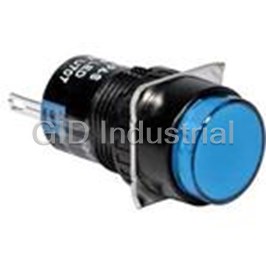
Switch Indicators 24VAC/24VDC LED Round Quick Connect/Solder Lug Panel Mount with Threads AL6M-P4-A
Switch Indicators 24VAC/24VDC LED Round Quick Connect/Solder Lug Panel Mount with Threads AL6M-P4-JW
Switch Indicators 24VAC/24VDC LED Round Quick Connect/Solder Lug Panel Mount with Threads AL6M-P4P-A
Request a Quote

The quote request has been received
Close

Facing challenges or have inquiries? Feel free to contact us!
Call Us +1-469-283-2440
What they say about us
FANTASTIC RESOURCE
One of our top priorities is maintaining our business with precision, and we are constantly looking for affiliates that can help us achieve our goal. With the aid of GID Industrial, our obsolete product management has never been more efficient. They have been a great resource to our company, and have quickly become a go-to supplier on our list!
Bucher Emhart Glass
EXCELLENT SERVICE
With our strict fundamentals and high expectations, we were surprised when we came across GID Industrial and their competitive pricing. When we approached them with our issue, they were incredibly confident in being able to provide us with a seamless solution at the best price for us. GID Industrial quickly understood our needs and provided us with excellent service, as well as fully tested product to ensure what we received would be the right fit for our company.
Fuji
HARD TO FIND A BETTER PROVIDER
Our company provides services to aid in the manufacture of technological products, such as semiconductors and flat panel displays, and often searching for distributors of obsolete product we require can waste time and money. Finding GID Industrial proved to be a great asset to our company, with cost effective solutions and superior knowledge on all of their materials, it’d be hard to find a better provider of obsolete or hard to find products.
Applied Materials
CONSISTENTLY DELIVERS QUALITY SOLUTIONS
Over the years, the equipment used in our company becomes discontinued, but they’re still of great use to us and our customers. Once these products are no longer available through the manufacturer, finding a reliable, quick supplier is a necessity, and luckily for us, GID Industrial has provided the most trustworthy, quality solutions to our obsolete component needs.
Nidec Vamco
TERRIFIC RESOURCE
This company has been a terrific help to us (I work for Trican Well Service) in sourcing the Micron Ram Memory we needed for our Siemens computers. Great service! And great pricing! I know when the product is shipping and when it will arrive, all the way through the ordering process.
Trican Well Service
GO TO SOURCE
When I can't find an obsolete part, I first call GID and they'll come up with my parts every time. Great customer service and follow up as well. Scott emails me from time to time to touch base and see if we're having trouble finding something.....which is often with our 25 yr old equipment.
ConAgra Foods