

 Manufacturers
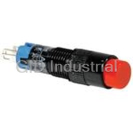
IDEC CORPORATION APS116DN-W

Description
Dome Pilot Light
APS116DN-W
Part Number
APS116DN-W
Price
Request Quote
Manufacturer
IDEC CORPORATION
Lead Time
Request Quote
Category
Thermal Management » Misc Products
Specifications
Manufacturer
IDEC Corporation
Manufacturers Part #
APS116DN-W
Lead Time
4 Week Lead Time
Industry Aliases
APS116DNW
Sub-Categories
Miscellaneous Tools and Supplies
Factory Pack Quantity
1
Datasheet

Extracted Text
��������� ����� ������������ ������� ����� �� ø25mm TWS Series Control Units �������� ����� ������������ �� ���� ������ ø25 TWS Series Control Units (Selection Guide) Function Pushbutton Extended with Extended with Flush Extended Mushroom Half Shroud Full Shroud Category Momentary/Maintained Shape ABS1 ABS2 ABGS2 ABFS2 ABS3 Type AOS1 AOS2 AOGS2 AOFS2 AOS3 Page 9999 10 Function Pushbutton Mushroom with Mushroom Pushlock Mushroom Full Shroud Category Mushroom Push-Pull Turn Reset Push Turn Lock Momentary/Maintained Shape ABGS3 Type AVS3 AJS3 AYS3 AOGS3 Page 10 10 10 11 Function Pushbutton Square Flush Square Extended Square Twin Square Twin Category Momentary/Maintained Momentary Maintained Shape UBQS1 Type UBQS2 UWQN1 UWQN2 UOQS1 Page 11 11 12 12 Function Pilot Light (LED/Incandescent) Dome Square (Marking) Square (Marking) Rectangular (Marking) Category Dome (Plastic Bezel) (Metal Bezel) (Plastic Bezel) Push-to-Check Shape Type APS1 UPQS1B UPQMS1B UPQS4B APS1∗PN Page 13 13 13 13 13 2 �������� ����� ������������ �� ���� ������ TWS Series Control Units (Selection Guide) ø25 Function Illuminated Pushbutton (LED/Incandescent) Extended with Extended with Extended ø35mm Mushroom Mushroom Pushlock Category Half Shroud Full Shroud (Non-marking) (Non-marking) Turn Reset (Non-marking) (Non-marking) Shape ALS2 ALGS2 ALFS2 ALS3 Type AVLS3 AOLS2 AOLGS2 AOLFS2 AOLS3 Page 15 16 17 18 18 Illuminated Illuminated Selector Function Pushbutton Selector Switch Switch (LED/Incandescent) (LED/Incandescent) Square Flush Category Knob Lever Key Knob (Marking) Shape ULQS1B Type ASS ASS∗L ASS∗KASLS UOLQS1B Page 19 21 22 23 24 3 �������� ����� ������������ �� ���� ������ ø25 TWS Series Control Units Highly reliable heavy-duty type control units Suitable for industrial use • HW-C contact blocks are used. • Degree of protection: IP65 (IEC 60529) • UL and CSA approved, EN compliant Safety Standards File No. or Organization UL Listing UL File No. E68961 CSA File No. LR21451 EN60947-1 EN TÜV Rheinland EN60947-5-1 Specifications and Ratings Contact Ratings Rated Insulation Voltage 600V Rated Continuous Current 10A Contact Block Contact Ratings by Utilization Category AC-15 (A600) IEC 60947-5-1 DC-13 (P600) Characteristics • Contact Ratings by Utilization Category Operational Voltage 24V 48V 50V 110V 220V 440V AC-12 Control of resistive loads and solid state loads 10A — 10A 10A 6A 2A AC 50/60 Hz AC-15 Control of electromagnetic loads (> 72 VA) 10A — 7A 5A 3A 1A Operational Current DC-12 Control of resistive loads and solid state loads 8A 4A — 2.2A 1.1A — DC DC-13 Control of electromagnets 4A 2A — 1.1A 0.6A — Minimum applicable load: 3V AC/DC, 5 mA (applicable range may vary with operating conditions and load types) For the control units listed below, the rated current (load switching current) is reduced to a half of the rated operational current of the con- tact block. The rated insulation voltage (600V) and the rated thermal current (10A) remain unchanged. • Selector switches and illuminated selector switches with contact code 2R, 3S, 4S, or 4R. HW-C (Contact Block) • M3.5 terminal screw 2-way wiring possible • Double-break rolling action silver contacts with raked surface • Snap-fit groove • Alkali-resistant • Fitting groove 66 nylon housing • Contact Block Types Contact NO NC NO (early make) NC (late break) Housing Blue Purple red Blue Purple red Push Rod Green Red Black White • Push rod Color-coded for different contacts • Snap-fit latch A maximum of four contact blocks in two layers can mount on the operator. Note: BS type contact block is used for square twin pushbuttons UWQN1 and UWQN2. 4 �������� ����� ������������ �� ���� ������ TWS Series Control Units ø25 Specifications Operating Temperature –25 to +50°C (no freezing) Operating Humidity 45 to 85% RH (no condensation) Contact Resistance 50 mΩ maximum (initial value) Insulation Resistance 100 MΩ minimum (500V DC megger) Between live and dead metal parts: 2,500V AC, 1 minute Dielectric Strength (Full voltage type illuminated units: 2,000V AC, 1 minute) Vibration Resistance Operating extremes: 5 to 55 Hz, amplitude 0.5 mm 2 Damage limits: 1,000 m/s Shock Resistance 2 Operating extremes: 100 m/s Pushbuttons, Illuminated pushbuttons Momentary: 5,000,000 Others: 500,000 Mechanical Life (minimum operations) Pushlock turn reset: 250,000 Selector switches: 500,000 Key selector switches: 500,000 Illuminated selector switches: 500,000 Pushbuttons: 500,000 ∗1 Illuminated pushbuttons: 500,000 ∗1 Pushlock turn reset: 250,000 ∗1 Square twin maintained: 500,000 ∗2 Selector switches: 500,000 ∗3 Electrical Life (minimum operations) Key selector switches: 500,000 ∗3 Illuminated selector switches: 250,000 ∗3 Others: 500,000 ∗1 ∗1 Switching frequency 1,800 operations/h, duty ratio 40% ∗2 Switching frequency 900 operations/h, duty ratio 40% ∗3 Switching frequency 1,200 operations/h, duty ratio 40% LED Illuminated Unit Specifications LED Lamp Unit Color Code ➁ Input Type Operating Voltage Lamp Base Type No. Voltage 6V AC/DC LSTD-6➁ 6V AC/DC ±10% Full Voltage 12V AC/DC LSTD-1➁ 12V AC/DC ±10% 24V AC/DC LSTD-2➁ 24V AC/DC ±10% A: amber 100/110V AC/DC G: green 115V AC/DC Pilot Light PW: pure white 120V AC/DC Illuminated Pushbutton R: red BA9S/13 200/220V AC/DC S: blue Illuminated Selector Switch Transformer 230V AC/DC LSTD-6➁ 6V AC/DC ±10% W: white 240V AC/DC Y: yellow 380V AC/DC 400/440V AC/DC (50/60 Hz) DC-DC Converter 110V DC LSTD-6➁ 6V AC/DC ±10% Incandescent Illuminated Unit Specifications Incandescent Lamp Unit Color Code ➁ Input Type Operating Voltage Lamp Base Type No. Rating 6V AC/DC LS-6 1W (6.3V) Full Voltage 12V AC/DC BA9S/13 LS-8 1W (18V) 24V AC/DC LS-3 1W (30V) 100/110V AC/DC A: amber 115V AC/DC C: clear Pilot Light 120V AC/DC G: green Illuminated Pushbutton 200/220V AC/DC R: red Illuminated Selector Switch 230V AC/DC S: blue Transformer BA9S/13 LS-6 1W (6.3V) 240V AC/DC W: white 380V AC/DC 400/440V AC/DC 480V AC/DC (50/60 Hz) 5 �������� ����� ������������ �� ���� ������ ø25 TWS Series Control Units LED Lamp Ratings (LSTD Type) Type No. LSTD-6➁ LSTD-1➁ LSTD-2➁ Lamp Base BA9S/13 Rated Voltage 6V AC/DC 12V AC/DC 24V AC/DC Voltage Range 6V AC/DC ±10% 12V AC/DC ±10% 24V AC/DC ±10% AC A, R, W, Y: 17 mA, G, PW, S: 8 mA 11 mA 11 mA Current Draw DC A, R, W, Y: 14 mA, G, PW, S: 5.5 mA 10 mA 10 mA Color Code ➁ A (amber), G (green), PW (pure white), R (red), S (blue), W (white), Y (yellow) Lamp Base Color Same as illumination color Voltage Marking Die stamped on the base Life (reference value) Approx. 50,000 hours (The luminance is reduced to 50% the initial intensity when used on complete DC.) A, R, W, Y Internal Circuit G, PW, S LED Chip Protection Diode Zener Diode Incandescent Lamp Ratings (LS Type) Type No. LS-6 LS-8 LS-2 LS-3 Lamp Base BA9S/13 Rated Voltage 6V AC/DC 12V AC/DC 18V AC/DC 24V AC/DC Wattage 1W (6.3V) 1W (18V) 1W (24V) 1W (30V) Voltage Marking Die stamped on the base Approx. 1,000 hours minimum Life (reference value) (mean value when used on the rated voltage) Mounting Hole Layout ø5 Note: The minimum mounting centers are applicable to switches with one layer of contact Note: blocks (two contact blocks). When two layers of contact blocks are mounted, determine ø5 recess is for preventing rotation and is not necessary when a the minimum mounting centers in consideration of convenience for wiring. nameplate or anti-rotation ring is • ø35mm mushroom: 35 mm minimum not used. • Mushroom with shroud: 42 mm minimum • 2-position, 3-position lever type selector switch: 42 mm minimum • 4-position, 5-position lever type selector switch: 50 mm minimum Round Type 34 (∗) 45 Square Type Degree of Protection Type No. Unit NEMA ICS 6-110 IEC 60529 Pushbuttons, pilot lights, illuminated pushbutons, and selector switches Type 1, 2, 3, 3R, 4, 5, 12,13 IP65 A∗∗∗∗ Illuminated selector switches and key selector switches Type 1, 2, 3R, 5, 12, 13 IP54 U∗∗∗∗ Square pushbuttons, square pilot lights, and square illuminated pushbuttons Type 1, 2 IP40 6 +0.5 0 ø25.5 ( ) 50 45min. �������� ����� ������������ �� ���� ������ TWS Series Control Units (Ordering Information) ø25 Ordering Information Standard Units Terminal Cover • Specify an operator or lens color code in the Type No. • When a terminal cover is required, order an applicable terminal cover referring to page 29. • Full voltage type illuminated units are not supplied with a lamp. Order LED or incandescent lamps separately. Transformer and DC-DC converter type illuminated units contain an LED or incandescent lamp. • All standard units are UL, CSA, EN, and TÜV approved (except DC-DC converter type). • Terminal covers, nameplates, and accessories are ordered separately. The Type No. development charts shown below can be used to specify control units other than those listed on the following pages. Pushbuttons Illuminated Pushbuttons ABS1 11 N R ALFS2 126 13 D N R Button color code Lens color code Contact arrangement code Lamp type 10: 1NO 01: 1NC D: LED (Transformer type only) 11: 1NO-1NC 20: 2NO (blank): Incandescent 02: 2NC 21: 2NO-1NC 12: 1NO-2NC 30: 3NO Contact arrangement code 03: 3NC 31: 3NO-1NC 11: 1NO-1NC 20: 2NO 22: 2NO-2NC 13: 1NO-3NC 02: 2NC 31: 3NO-1NC 40: 4NO 04: 4NC 22: 2NO-2NC 13: 1NO-3NC 40: 4NO 04: 4NC Operating voltage code 99: Full voltage Note: 16: Transformer (100/110V AC) • Push-pull type AYS3 can have a maximum of two contact blocks. 116: Transformer (115V AC) 126: Transformer (120V AC) 26: Transformer (200/220V AC) Pilot Lights 236: Transformer (230V AC) 246: Transformer (240V AC) APS1 116 D N R 386: Transformer (380V AC) Lens color code 46: Transformer (400/440V AC) Lamp type 486: Transformer (480V AC) D: LED (Transformer type only) 16∗D: DC-DC converter (110V DC) (blank): Incandescent Operating voltage code 99: Full voltage Note: 16: Transformer (100/110V AC) • Full voltage type is not supplied with a lamp. 116: Transformer (115V AC) • Transformer and DC-DC converter types contain an LED lamp 126: Transformer (120V AC) (LSTD-6➁) or incandescent lamp (LS-6). 26: Transformer (200/220V AC) 236: Transformer (230V AC) 246: Transformer (240V AC) 386: Transformer (380V AC) 46: Transformer (400/440V AC) 486: Transformer (480V AC) 16D: DC-DC converter (110V DC) Note: • Full voltage type is not supplied with a lamp. • Transformer and DC-DC converter types contain an LED lamp (LSTD-6➁) or incandescent lamp (LS-6). 7 �������� ����� ������������ �� ���� ������ ø25 TWS Series Control Units (Ordering Information) Selector Switch Illuminated Selector Switch ASS 2 L 11 N ASLS 2 16 22 D N R Contact arrangement code Lens color code Lamp type Operator type D: LED (Transformer type only) (blank): Knob (blank): Incandescent L: Lever Contact arrangement code Number of positions Operating voltage code 99: Full voltage 16: Transformer (100/110V AC) Note: 156: Transformer (115V AC) • See pages 26 to 28 for contact arrangement codes. 136: Transformer (120V AC) 26: Transformer (200/220V AC) Key Selector Switch 236: Transformer (230V AC) 256: Transformer (240V AC) ASS 2 K 20 N B 386: Transformer (380V AC) Key removable position code 46: Transformer (400/440V AC) 2-position 486: Transformer (480V AC) • Maintained Number of positions (blank): Removable in all positions Note: B: Removable in left only • Full voltage type is not supplied with a lamp. C: Removable in right only • Transformer type contains an LED lamp (LSTD-6➁) or incandes- • Spring return from right cent lamp (LS-6). (blank): Removable in left only • See pages 26 to 28 for contact arrangement codes. • Spring return from left (blank): Removable in right only 3-position • Maintained (blank): Removable in all positions B: Removable in left and center C: Removable in right and center D: Removable in center only E: Removable in right and left G: Removable in left only H: Removable in right only • Spring return from right (blank): Removable in left and center D: Removable in center only G: Removable in left only • Spring return from left (blank): Removable in right and center D: Removable in center only H: Removable in right only • Spring return two-way (blank): Removable in center only Contact arrangement code Number of positions Note: • See page 26 to 28 for contact arrangement codes. • The key cannot be removed in the return position. 8 �������� ����� ������������ �� ���� ������ TWS Series Pushbuttons ø25 Flush / Extended Types Operation ➀ Button Color Shape Contact Type No. Dimensions (mm) Type Code Flush 1NO ABS110N➀ ABS1 1NC ABS101N➀ M3.5 Terminal AOS1 Black (B), green Panel Thickness 0.8 to 6 Screw 1NO-1NC ABS111N➀ Momentary (G), and red (R) 2NO ABS120N➀ buttons are sup- 2NC ABS102N➀ plied with each 2NO-2NC ABS122N➀ unit as standard. 9 1NO AOS110N➀ 41.5 (1 or 30 2 blocks) 10.3 ø34 Specify S, W, or Y 1NC AOS101N➀ 61.5 (3 or 4 blocks) when a blue, 1NO-1NC AOS111N➀ Maintained white, or yellow 2NO AOS120N➀ Note: The depth behind the panel of the maintained button is required. type is 1.5mm longer than the momentary 2NC AOS102N➀ type. 2NO-2NC AOS122N➀ Extended 1NO ABS210N➀ ABS2 1NC ABS201N➀ M3.5 Terminal AOS2 Panel Thickness 0.8 to 6 Screw 1NO-1NC ABS211N➀ Momentary 2NO ABS220N➀ 2NC ABS202N➀ 2NO-2NC ABS222N➀ 9 1NO AOS210N➀ 41.5 (1 or 30 2 blocks) 16.3 ø34 1NC AOS201N➀ 61.5 (3 or 4 blocks) 1NO-1NC AOS211N➀ Maintained 2NO AOS220N➀ Note: The depth behind the panel of the maintained type is 1.5mm longer than the momentary 2NC AOS202N➀ type. 2NO-2NC AOS222N➀ Extended with Half Shroud 1NO ABGS210N➀ Specify a button ABGS2 1NC ABGS201N➀ M3.5 Terminal color code in AOGS2 1NO-1NC ABGS211N➀ Screw Panel Thickness 0.8 to 4 Momentary place of ➀ in the (Maintained type 0.8 to 6) 2NO ABGS220N➀ Type No. 2NC ABGS202N➀ 2NO-2NC ABGS222N➀ B: black G: green 1NO AOGS210N➀ 40 (1 or 30 2 blocks) R: red ø34 1NC AOGS201N➀ 60 (3 or 4 blocks) S: blue 1NO-1NC AOGS211N➀ W: white Maintained 2NO AOGS220N➀ Y: yellow Note: The depth behind the panel of the maintained 2NC AOGS202N➀ type is 1.5mm longer than the momentary type. 2NO-2NC AOGS222N➀ Extended with Full Shroud 1NO ABFS210N➀ ABFS2 1NC ABFS201N➀ M3.5 Terminal AOFS2 Panel Thickness 0.8 to 6 1NO-1NC ABFS211N➀ Screw Momentary 2NO ABFS220N➀ 2NC ABFS202N➀ 2NO-2NC ABFS222N➀ 1NO AOFS210N➀ ( 9 30 42 1 or 2 blocks) 17 ø34 1NC AOFS201N➀ ( 62 3 or 4 blocks) 1NO-1NC AOFS211N➀ Maintained 2NO AOFS220N➀ Note: The depth behind the panel of the maintained type is 1.5mm longer than the momentary 2NC AOFS202N➀ type. 2NO-2NC AOFS222N➀ • Specify a button color code in place of ➀ in the Type No. • Round bezel and shroud (metal): Chrome-plated • Pushbuttons with one or three contact blocks contain a dummy block. • Other contact arrangements are also available. See page 7. 9 ø20 ø19.5 ø19.5 ø24 ø30 ø30 ø22 ø30 ø30 37 37 37 37 K C O L �������� ������ �������������� ���� ������ ø25 TWS Series Pushbuttons Mushroom / Pushlock Turn Reset / Push Turn Lock Types Operation ➀ Button Color Shape Contact Type No. Dimensions (mm) Type Code Mushroom 1NO ABS310N➀ ABS3 1NC ABS301N➀ M3.5 Terminal AOS3 Panel Thickness 0.8 to 6 Screw 1NO-1NC ABS311N➀ Momentary 2NO ABS320N➀ 2NC ABS302N➀ 2NO-2NC ABS322N➀ 41.5 (1 or 9 30 1NO AOS310N➀ 2 blocks) 25 1NC AOS301N➀ Specify a button ( 61.5 3 or 4 blocks) 1NO-1NC AOS311N➀ color code in Maintained place of ➀ in the 2NO AOS320N➀ Note: The depth behind the panel of the maintained Type No. type is 1.5mm longer than the momentary 2NC AOS302N➀ type. 2NO-2NC AOS322N➀ B: black Mushroom with Full Shroud 1NO ABGS310N➀ G: green ABGS3 1NC ABGS301N➀ R: red M3.5 Terminal AOGS3 Screw Panel Thickness 0.8 to 6 1NO-1NC ABGS311N➀ S: blue Momentary W: white 2NO ABGS320N➀ Y: yellow 2NC ABGS302N➀ 2NO-2NC ABGS322N➀ 1NO AOGS310N➀ 41.5 (1 or 18.5 30 2 blocks) 25 1NC AOGS301N➀ 61.5 (3 or 4 blocks) 1NO-1NC AOGS311N➀ Maintained 2NO AOGS320N➀ Note: The depth behind the panel of the maintained type is 1.5mm longer than the momentary 2NC AOGS302N➀ type. 2NO-2NC AOGS322N➀ Pushlock Turn Reset 1NO AVS310N➀ M3.5 Terminal Panel Thickness 0.8 to 6 Screw AVS3 1NC AVS301N➀ 1NO-1NC AVS311N➀ R: red Y: yellow 2NO AVS320N➀ 43 (1 or 9 30 2NC AVS302N➀ 2 blocks) 25 2NO-2NC AVS322N➀ ( 63 3 or 4 blocks) Push Turn Lock 1NO AJS310N➀ M3.5 Terminal Panel Thickness 0.8 to 6 AJS3 Screw 1NC AJS301N➀ B: black 1NO-1NC AJS311N➀ G: green R: red 2NO AJS320N➀ Y: yellow ( 9 43 1 or 2 30 2NC AJS302N➀ blocks) 25 2NO-2NC AJS322N➀ ( 63 3 or 4 blocks) • Specify a button color code in place of ➀ in the Type No. • Round bezel (metal): Chrome-plated • Pushbuttons with one or three contact blocks contain a dummy block. • Other contact arrangements are also available. See page 7. • Pushlock Turn Reset: Button is maintained when pressed and is reset when turned clockwise. Note: AVS3 cannot be used as emergency stop switches. When emergency stop switches are required, use XW or HW series emergency stop switches (ISO 13850 and IEC 60947-5-5 compliant). • Push Turn Lock: Button is locked when turned clockwise in the depressed position and is reset when turned counterclockwise. 10 H S U P ø35 ø35 ø35 ø35 ø42 37 37 37 37 �������� ������ �������������� ���� ������ TWS Series Pushbuttons ø25 Push-Pull / Square Flush / Square Extended Types Operation ➀ Button Shape Contact Type No. Dimensions (mm) Type Color Code Mushroom Push-Pull 1NO AYS3110N➀ AYS31 M3.5 Terminal Panel Thickness 0.8 to 6 Screw 1NC AYS3101N➀ B: black G: green Maintained 1NO-1NC AYS3111N➀ R: red Y: yellow 9 2NO AYS3120N➀ 25 30 43 (1 or 30.5 2 blocks) 2NC AYS3102N➀ Square Flush 1NO UBQS110N➀ UBQS1 1NC UBQS101N➀ M3.5 Terminal Panel Thickness 0.8 to 4 Screw UOQS1 1NO-1NC UBQS111N➀ (Maintained type: 0.8 to 5) Momentary 2NO UBQS120N➀ 2NC UBQS102N➀ 2NO-2NC UBQS122N➀ 1NO UOQS110N➀ 44.5 (1 or 14 30 2 blocks) 14.3 1NC UOQS101N➀ 39.5 ( 64.5 3 or 4 blocks) 1NO-1NC UOQS111N➀ Maintained 2NO UOQS120N➀ Note: The depth behind the panel of the maintained B: black type is 1.5mm longer than the momentary type. 2NC UOQS102N➀ G: green R: red 2NO-2NC UOQS122N➀ S: blue Square Extended 1NO UBQS210N➀ Y: yellow UBQS2 M3.5 Terminal Panel Thickness 0.8 to 4 1NC UBQS201N➀ Screw (Maintained type: 0.8 to 5) 1NO-1NC UBQS211N➀ Momentary 2NO UBQS220N➀ ( 14 44.5 1 or 30 2 blocks) 19.8 2NC UBQS202N➀ 39.5 64.5 (3 or 4 blocks) 2NO-2NC UBQS222N➀ • Specify a button color code in place of ➀ in the Type No. • Round bezel (metal): Chrome-plated • Square bezel (plastic): Black • Pushbuttons with one or three contact blocks contain a dummy block. • Other contact arrangements are also available. See page 7. • Push-Pull: Button is maintained in both depressed and reset positions. Up to 2 contact blocks (1 layer) can be mounted on AYS31 push-pull switches. • Contact Statuses of Push-Pull Switch • Panel Mounting of Square Types AYS31 1. Tighten the square bezel to the operator and position the Contact Push Pull ring correctly. 1NO 2. Lightly tighten the screw to secure the pushbutton onto the panel. 1NC 1NO-1NC 2NO 2NC Tighten the screw lightly so that this plate does not bend. • Note: Push-pull switch can have a maximum of two contact blocks. Recommended tightening torque: 0.15 N·m 11 24.8 24.5 30 30 ø35 37 37 37 53 53 �������� ������ �������������� ���� ������ ø25 TWS Series Pushbuttons Square Twin Types Shape Contact Type No. Button Color Dimensions (mm) Square Twin (Momentary) ON OFF M3.5 Terminal Screw Panel Thickness 0.8 to 13 UWQN1 1NO 1NO UWQN11010 O N ON: Black OFF OFF: Red 1NO 1NC UWQN11001 6 23 36 53 47 (1 or 2 blocks) 15.5 ( ) 2NO 2NC UWQN12002 70 3 or 4 blocks Square Twin (Maintained) 1NO UWQN21000 UWQN2 Panel Thickness 0.8 to 13 M3.5 Terminal Screw 1NC UWQN20100 O N ON: Black 1NO-1NC UWQN21100 OFF OFF: Red 6 23 36 2NO UWQN22000 ) 47 (1 block 53 70 (2 blocks) 15.5 2NC UWQN20200 • Square Twin (Momentary): Two independent momentary switches are contained in one unit, each operated by ON or OFF button. With the ø30 adapter removed from the sleeve, the unit can mount in a ø25.5mm mounting hole for the ø25 series. • Square Twin (Maintained): The contact operates when ON button is pressed and is maintained in the depressed position. The button is reset by pressing the OFF button. With the ø30 adapter removed from the sleeve, the unit can mount in a ø25.5mm mounting hole for the ø25 series. 12 42 42 �������� ������ �������������� ���� ������ TWS Series Pilot Lights ø25 Dome / Square / Rectangular (Marking) Types ➁ Lens/LED Shape Lamp Input Type Type No. ➂ Operating Voltage Code Color Code Dome Without Lamp Full Voltage APS199N➁ A, C, G, R, S, W, Y APS1 Transformer APS1➂DN➁ LED A, G, PW, R, S, W, Y DC-DC Converter∗ APS116DDN➁ Incandescent Transformer APS1N➂➁ A, C, G, R, S, W Square (Marking) Without Lamp Full Voltage UPQS1B99N➁ A, G, R, S, W, Y UPQS1B (Plastic Bezel) LED Transformer UPQS1B➂DN➁ A, G, PW, R, S, W, Y Incandescent Transformer UPQS1B➂N➁ A, G, R, S, W Specify an operating voltage code in place of ➂ Square (Marking) in the Type No. UPQMS1B (Metal Bezel) Without Lamp Full Voltage UPQMS1B99N➁ A, G, R, S, W, Y 16: 100/110V AC 116: 115 AC 126: 120V AC LED Transformer UPQMS1B➂DN➁ A, G, PW, R, S, W, Y 26: 200/220V AC 236: 230V AC 246: 240V AC Incandescent Transformer UPQMS1B➂N➁ A, G, R, S, W 386: 380V AC 46: 400/440V AC Rectangular (Marking) 486: 480V AC UPQS4B (Plastic Bezel) Without Lamp Full Voltage UPQS4B99N➁ A, G, R, S, W Incandescent Transformer UPQS4B➂N➁ Push-to-Check APS1∗PN Without Lamp Full Voltage APS199PN➁ A, C, G, R, S, W Incandescent Transformer APS1➂PN➁ • Color Code Specify a lens/LED color code in place of ➁ in the Type No. A: amber, C: clear, G: green, PW: pure white, R: red, S: blue, W: white, Y: yellow • Specify an operating voltage code in place of ➂ in the Type No. • Full voltage types do not contain a lamp. Order LED or incandescent lamps separately. For lamps, see page 35. • LED illuminated transformer and DC-DC converter types contain an LED lamp (LSTD-6➁, rated voltage 6V AC/DC). • Incandescent illuminated transformer types contain an incandescent lamp (LS-6, rated voltage 6V AC/DC). • Round bezel (metal): Chrome-plated Square bezel (plastic): Black Square bezel (metal): Chrome-plated ∗ DC-DC converter types are not approved by UL, CSA, and TÜV, and not CE compliant (operating voltage 90 to 140V DC). • The lamp of push-to-check pilot light is not connected to the contact terminal. To connect, refer to the circuit diagram example below. START OLS STOP M M L Push-to-Check Pilot Light 13 �������� ������ �������������� ���� ������ ø25 TWS Series Pilot Lights Dimensions • Square (Marking Type) • Dome UPQS1B (Plastic Bezel) APS1 M3.5 Terminal M3.5 Terminal Screw Panel Thickness 0.8 to 6 Panel Thickness 0.8 to 6 Screw A: 22.5 9 31.2 A: 32.5 8 31.2 B: 59 22.5 ø34 B: 69 10 39.5 Marking Plate Size: 21.2×1t mm, 2 plates included A: Full voltage type A: Full voltage type B: Transformer type B: Transformer type • Rectangular (Marking Type) • Square (Marking Type) UPQS4B UPQMS1B (Metal Bezel) M3.5 Terminal M3.5 Terminal Screw Panel Thickness 0.8 to 6 Screw Panel Thickness 0.8 to 6 A: 32.5 8 31.2 A: 32.5 6.5 31.2 B: 69 10 35 B: 69 10.5 39.5 39.5 Marking Plate Size: 20×2t mm, 1 plate included Marking Plate Size: 27.2×21.2×1t mm, 2 plates included A: Full voltage type A: Full voltage type B: Transformer type B: Transformer type • Push-to-Check APS1∗ ∗ ∗ ∗PN M3.5 Terminal Screws Panel Thickness 0.8 to 6 A: 67 (2 blocks) 9 30 All dimensions in mm. ( ) B: 90 2 blocks 22.5 ø34 A: Full voltage type B: Transformer type • Terminal Wiring (Bottom View) • Panel Mounting of Square and Rectangular Types Arrows indicate access directions for wiring. 1. Tighten the square or rectangular bezel to the operator and position the ring correctly. Transformer Type Full Voltage Type 2. Lightly tighten the screw to secure the pilot light onto the DC-DC Converter Type panel. M3.5 M3.5 X1 Tighten the screw lightly so that X1 this plate does not bend. X2 X2 Recommended tightening torque: 0.15 N·m 14 24 ø19.6 29 ø30 ø19.6 ø30 37 37 37 53 24.5 24.5 29 29 37 37 53 53 �������� ������ �������������� ���� ������ TWS Series Illuminated Pushbuttons ø25 Round Extended Illuminated Pushbuttons Shape Operation Type Lamp Input Type Contact Type No. Round Extended 1NO-1NC ALS29911N➁ ALS2 Without Lamp Full Voltage 2NO ALS29920N➁ AOLS2 2NO-2NC ALS29922N➁ 1NO-1NC ALS2➂11DN➁ Transformer 2NO ALS2➂20DN➁ 2NO-2NC ALS2➂22DN➁ Momentary LED 1NO-1NC ALS21611DDN➁ DC-DC Converter∗ 2NO ALS21620DDN➁ 2NO-2NC ALS21622DDN➁ 1NO-1NC ALS2➂11N➁ Incandescent Transformer 2NO ALS2➂20N➁ 2NO-2NC ALS2➂22N➁ 1NO-1NC AOLS29911N➁ Without Lamp Full Voltage 2NO AOLS29920N➁ 2NO-2NC AOLS29922N➁ 1NO-1NC AOLS2➂11DN➁ Transformer 2NO AOLS2➂20DN➁ 2NO-2NC AOLS2➂22DN➁ Maintained LED 1NO-1NC AOLS21611DDN➁ DC-DC Converter∗ 2NO AOLS21620DDN➁ 2NO-2NC AOLS21622DDN➁ 1NO-1NC AOLS2➂11N➁ Incandescent Transformer 2NO AOLS2➂20N➁ 2NO-2NC AOLS2➂22N➁ • Color Code and Operating Voltage Code Without Lamp LED Illuminated Type Incandescent Illuminated Type ➂ Operating Voltage Code ➁ Lens Color Code ➁ Lens/LED Color Code ➁ Lens Color Code Specify a lens color code in place Specify a lens/LED color code in Specify a lens color code in place Specify an operating voltage of ➁ in the Type No. place of ➁ in the Type No. of ➁ in the Type No. code in place of ➂ in the Type No. A: amber A: amber A: amber 16: 100/110V AC C: clear G: green C: clear 116: 115V AC G: green PW: pure white G: green 126: 120V AC R: red R: red R: red 26: 200/220V AC S: blue S: blue S: blue 236: 230V AC W: white W: white W: white 246: 240V AC Y: yellow Y: yellow 386: 380V AC 46: 400/440V AC 486: 480V AC • Full voltage types do not contain a lamp. Order LED or incandescent lamps separately. For lamps, see page 35. • LED illuminated transformer and DC-DC converter types contain an LED lamp (LSTD-6➁, rated voltage 6V AC/DC). • Incandescent illuminated transformer types contain an incandescent lamp (LS-6, rated voltage 6V AC/DC). • Round bezel (metal): Chrome-plated • Other contact arrangements are also available. See page 7. ∗ DC-DC converter types are not approved by UL, CSA, and TÜV, and not CE compliant (operating voltage 90 to 140V DC). 15 TWS_IPB Page16 Tuesday,June14,2005 10:09AM ø25 TWS Series Illuminated Pushbuttons Round Extended with Half Shroud Illuminated Pushbuttons Shape Operation Type Lamp Input Type Contact Type No. Round Extended 1NO-1NC ALGS29911N➁ with Half Shroud Without Lamp Full Voltage 2NO ALGS29920N➁ ALGS2 2NO-2NC ALGS29922N➁ AOLGS2 1NO-1NC ALGS2➂11DN➁ Transformer 2NO ALGS2➂20DN➁ 2NO-2NC ALGS2➂22DN➁ Momentary LED 1NO-1NC ALGS21611DDN➁ DC-DC Converter∗ 2NO ALGS21620DDN➁ 2NO-2NC ALGS21622DDN➁ 1NO-1NC ALGS2➂11N➁ Incandescent Transformer 2NO ALGS2➂20N➁ 2NO-2NC ALGS2➂22N➁ 1NO-1NC AOLGS29911DN➁ Without Lamp Full Voltage 2NO AOLGS29920DN➁ 2NO-2NC AOLGS29922DN➁ 1NO-1NC AOLGS2➂11DN➁ Transformer 2NO AOLGS2➂20DN➁ 2NO-2NC AOLGS2➂22DN➁ Maintained LED 1NO-1NC AOLGS21611DDN➁ DC-DC Converter∗ 2NO AOLGS21620DDN➁ 2NO-2NC AOLGS21622DDN➁ 1NO-1NC AOLGS2➂11N➁ Incandescent Transformer 2NO AOLGS2➂20N➁ 2NO-2NC AOLGS2➂22N➁ • Color Code and Operating Voltage Code Without Lamp LED Illuminated Type Incandescent Illuminated Type ➂ Operating Voltage Code ➁ Lens Color Code ➁ Lens/LED Color Code ➁ Lens Color Code Specify a lens color code in place Specify a lens/LED color code in Specify a lens color code in place Specify an operating voltage of ➁ in the Type No. place of ➁ in the Type No. of ➁ in the Type No. code in place of ➂ in the Type No. A: amber A: amber A: amber 16: 100/110V AC C: clear G: green C: clear 116: 115V AC G: green PW: pure white G: green 126: 120V AC R: red R: red R: red 26: 200/220V AC S: blue S: blue S: blue 236: 230V AC W: white W: white W: white 246: 240V AC Y: yellow Y: yellow 386: 380V AC 46: 400/440V AC 486: 480V AC • Full voltage types do not contain a lamp. Order LED or incandescent lamps separately. For lamps, see page 35. • LED illuminated transformer and DC-DC converter types contain an LED lamp (LSTD-6➁, rated voltage 6V AC/DC). • Incandescent illuminated transformer types contain an incandescent lamp (LS-6, rated voltage 6V AC/DC). • Round bezel (metal): Chrome-plated • Other contact arrangements are also available. See page 7. ∗ DC-DC converter types are not approved by UL, CSA, and TÜV, and not CE compliant (operating voltage 90 to 140V DC). 16 �������� ������ �������������� ���� ������ TWS Series Illuminated Pushbuttons ø25 Round Extended with Full Shroud Illuminated Pushbuttons Shape Operation Type Lamp Input Type Contact Type No. Round Extended 1NO-1NC ALFS29911N➁ with Full Shroud Without Lamp Full Voltage 2NO ALFS29920N➁ ALFS2 2NO-2NC ALFS29922N➁ AOLFS2 1NO-1NC ALFS2➂11DN➁ Transformer 2NO ALFS2➂20DN➁ 2NO-2NC ALFS2➂22DN➁ Momentary LED 1NO-1NC ALFS21611DDN➁ DC-DC Converter∗ 2NO ALFS21620DDN➁ 2NO-2NC ALFS21622DDN➁ 1NO-1NC ALFS2➂11N➁ Incandescent Transformer 2NO ALFS2➂20N➁ 2NO-2NC ALFS2➂22N➁ 1NO-1NC AOLFS29911N➁ Without Lamp Full Voltage 2NO AOLFS29920N➁ 2NO-2NC AOLFS29922N➁ 1NO-1NC AOLFS2➂11DN➁ Transformer 2NO AOLFS2➂20DN➁ 2NO-2NC AOLFS2➂22DN➁ Maintained LED 1NO-1NC AOLFS21611DDN➁ DC-DC Converter∗ 2NO AOLFS21620DDN➁ 2NO-2NC AOLFS21622DDN➁ 1NO-1NC AOLFS2➂11N➁ Incandescent Transformer 2NO AOLFS2➂20N➁ 2NO-2NC AOLFS2➂22N➁ • Color Code and Operating Voltage Code Without Lamp LED Illuminated Type Incandescent Illuminated Type ➂ Operating Voltage Code ➁ Lens Color Code ➁ Lens/LED Color Code ➁ Lens Color Code Specify a lens color code in place Specify a lens/LED color code in Specify a lens color code in place Specify an operating voltage of ➁ in the Type No. place of ➁ in the Type No. of ➁ in the Type No. code in place of ➂ in the Type No. A: amber A: amber A: amber 16: 100/110V AC C: clear G: green C: clear 116: 115V AC G: green PW: pure white G: green 126: 120V AC R: red R: red R: red 26: 200/220V AC S: blue S: blue S: blue 236: 230V AC W: white W: white W: white 246: 240V AC Y: yellow Y: yellow 386: 380V AC 46: 400/440V AC 486: 480V AC • Full voltage types do not contain a lamp. Order LED or incandescent lamps separately. For lamps, see page 35. • LED illuminated transformer and DC-DC converter types contain an LED lamp (LSTD-6➁, rated voltage 6V AC/DC). • Incandescent illuminated transformer types contain an incandescent lamp (LS-6, rated voltage 6V AC/DC). • Round bezel (metal): Chrome-plated • Other contact arrangements are also available. See page 7. ∗ DC-DC converter types are not approved by UL, CSA, and TÜV, and not CE compliant (operating voltage 90 to 140V DC). 17 �������� ������ �������������� ���� ������ ø25 TWS Series Illuminated Pushbuttons Mushroom / Mushroom Pushlock Turn Reset Illuminated Pushbuttons Shape Operation Type Lamp Input Type Contact Type No. ø35mm Mushroom 1NO-1NC ALS39911N➁ ALS3 Without Lamp Full Voltage 2NO ALS39920N➁ AOLS3 2NO-2NC ALS39922N➁ Momentary 1NO-1NC ALS3➂11N➁ Incandescent Transformer 2NO ALS3➂20N➁ 2NO-2NC ALS3➂22N➁ 1NO-1NC AOLS39911N➁ Without Lamp Full Voltage 2NO AOLS39920N➁ 2NO-2NC AOLS39922N➁ Maintained 1NO-1NC AOLS3➂11N➁ Incandescent Transformer 2NO AOLS3➂20N➁ 2NO-2NC AOLS3➂22N➁ Mushroom Pushlock Turn Reset 1NO-1NC AVLS39911NR AVLS3 Without Lamp Full Voltage 2NO AVLS39920NR 2NO-2NC AVLS39922NR 1NO-1NC AVLS3➂11DNR LED Transformer 2NO AVLS3➂20DNR 2NO-2NC AVLS3➂22DNR 1NO-1NC AVLS3➂11NR Incandescent Transformer 2NO AVLS3➂20NR 2NO-2NC AVLS3➂22NR • Color Code and Operating Voltage Code Without Lamp / LED Illuminated Type Incandescent Illuminated Type ➂ Operating Voltage Code ➁ Lens/LED Color Code ➁ Lens Color Code Specify a lens/LED color code in place of ➁ Specify a lens color code in place of ➁ in the Specify an operating voltage code in place of in the Type No. Type No. ➂ in the Type No. A: amber A: amber 16: 100/110V AC G: green G: green 116: 115V AC R: red R: red 126: 120V AC S: blue S: blue 26: 200/220V AC W: white W: white 236: 230V AC 246: 240V AC 386: 380V AC 46: 400/440V AC 486: 480V AC • Full voltage types do not contain a lamp. Order LED or incandescent lamps separately. For lamps, see page 35. • LED illuminated transformer types contain an LED lamp (LSTD-6➁, rated voltage 6V AC/DC). • Incandescent illuminated transformer types contain an incandescent lamp (LS-6, rated voltage 6V AC/DC). • Round bezel (metal): Chrome-plated • Other contact arrangements are also available. See page 7. • Pushlock Turn Reset: Lens is maintained when pressed and is reset when turned clockwise. Red lens only. Note: AVLS3 pushlock turn reset switches cannot be used as emergency stop switches. When emergency stop switches are required, use XW or HW series emergency stop switches (ISO 13850 and IEC 60947-5-5 compliant). 18 �������� ������ �������������� ���� ������ TWS Series Illuminated Pushbuttons ø25 Square Flush Pushbuttons Shape Operation Type Lamp Input Type Contact Type No. Square Flush (Marking) 1NO-1NC ULQS1B9911N➁ ULQS1B Without Lamp Full Voltage 2NO ULQS1B9920N➁ UOLQS1B 2NO-2NC ULQS1B9922N➁ 1NO-1NC ULQS1B➂11DN➁ Momentary LED Transformer 2NO ULQS1B➂20DN➁ 2NO-2NC ULQS1B➂22DN➁ 1NO-1NC ULQS1B➂11N➁ Incandescent Transformer 2NO ULQS1B➂20N➁ 2NO-2NC ULQS1B➂22N➁ 1NO-1NC UOLQS1B9911N➁ Without Lamp Full Voltage 2NO UOLQS1B9920N➁ 2NO-2NC UOLQS1B9922N➁ 1NO-1NC UOLQS1B➂11DN➁ Maintained LED Transformer 2NO UOLQS1B➂20DN➁ 2NO-2NC UOLQS1B➂22DN➁ 1NO-1NC UOLQS1B➂11N➁ Incandescent Transformer 2NO UOLQS1B➂20N➁ 2NO-2NC UOLQS1B➂22N➁ • Color Code and Operating Voltage Code Without Lamp LED Illuminated Type Incandescent Illuminated Type ➂ Operating Voltage Code ➁ Lens Color Code ➁ Lens/LED Color Code ➁ Lens Color Code Specify a lens color code in place Specify a lens/LED color code in Specify a lens color code in place Specify an operating voltage of ➁ in the Type No. place of ➁ in the Type No. of ➁ in the Type No. code in place of ➂ in the Type No. A: amber A: amber A: amber 16: 100/110V AC G: green G: green G: green 116: 115V AC R: red PW: pure white R: red 126: 120V AC S: blue R: red S: blue 26: 200/220V AC W: white S: blue W: white 236: 230V AC Y: yellow W: white 246: 240V AC Y: yellow 386: 380V AC 46: 400/440V AC 486: 480V AC • Full voltage types do not contain a lamp. Order LED or incandescent lamps separately. For lamps, see page 35. • LED illuminated transformer types contain an LED lamp (LSTD-6➁, rated voltage 6V AC/DC). • Incandescent illuminated transformer types contain an incandescent lamp (LS-6, rated voltage 6V AC/DC). • Square bezel (plastic): Black • Other contact arrangements are also available. See page 7. 19 �������� ������ �������������� ���� ������ ø25 TWS Series Illuminated Pushbuttons Dimensions • Round Extended • Round Extended with Half Shroud ALS2 / AOLS2 ALGS2 / AOLGS2 M3.5 Terminal M3.5 Terminal Screws Panel Thickness 0.8 to 6 Screws Panel Thickness 0.8 to 6 ( ) A: 67 (2 blocks) A: 65.5 2 blocks 85.5 (4 blocks) 30 87 (4 blocks) 30 9 B: 88.5 (2 blocks), 108.5 (4 blocks) ( ), ( 21 ø34 B: 90 2 blocks 110 4 blocks) 19.5 ø34 A: Full voltage type A: Full voltage type B: Transformer type B: Transformer type • Round Extended with Full Shroud • ø35mm Mushroom ALFS2 / AOLFS2 ALS3 / AOLS3 M3.5 Terminal M3.5 Terminal Screws Panel Thickness 0.8 to 6 Screws Panel Thickness 0.8 to 6 ( ) A: 67 (2 blocks) A: 67 2 blocks 87 (4 blocks) 9 30 87 (4 blocks) 30 ( ), ( ) ( ), ( ) B: 90 2 blocks 110 4 blocks 25 B: 90 2 blocks 110 4 blocks 19.5 ø34 A: Full voltage type A: Full voltage type B: Transformer type B: Transformer type • Square Flush • Mushroom Pushlock Turn Reset ULQS1B / UOLQS1B AVLS3 M3.5 Terminal M3.5 Terminal Screws Panel Thickness 0.8 to 6 Panel Thickness 0.8 to 5 Screws A: 67 (2 blocks) ( ) A: 70 2 blocks ( ) ( ) 87 4 blocks 9 30 90 4 blocks 19 30 B: 90 (2 blocks), 110 (4 blocks) 25 ( ), ( ) B: 93 2 blocks 113 4 blocks 20.5 39.5 Marking Plate Size: 21.2x1t mm, 2 plates included A: Full voltage type A: Full voltage type B: Transformer type B: Transformer type All dimensions in mm. 20 25 ø19.5 ø35 ø30 ø30 37 37 37 ø19.5 24.5 ø35 ø22 30 ø30 37 37 37 53 ������ ������ ������������ ������� ����� �� TWS Series Selector Switches ø25 Selector Switches (Knob Operator Type) Panel Thickness 0.8 to 6 Shape ASS M3.5 Terminal Screw 43 (2 blocks) 9 30 ( ) 22 ø34 63 4 blocks Contact Arrangement Chart Maintained Spring Return Spring Return Contact Block Operator Position from Right from Left Contact — L R L R L R Code Mounting Type LR Position 1 NO 10 ASS210N ASS2110N ASS2210N ∗ (1NO) Dummy 2 1 NO 11 ASS211N ASS2111N ASS2211N ∗ (1NO-1NC) 2 NC 1 NO 20 ASS220N ASS2120N ASS2220N ∗ (2NO) 2 NO NO 1 — 22 2 NC ASS222N ASS2122N ASS2222N ∗ (2NO-2NC) NO 3 4 NC NO 2R ★ 1 ASS22RN-118 ★ ASS212RN-118 ★ — (1NO-1NC) 2 NC NC 2R ★ 1 —— ASS222RN-169 ★ (1NO-1NC) 2 NO Maintained Spring Return Spring Return Spring Return Contact Block Operator Position from Right from Left Two-way Contact C C C C L R L R L R L R Code Mounting Type LC R Position 1 NO 20 ASS320N ASS3120N ASS3220N ASS3320N (2NO) 2 NO 1 NC 02 ASS302N ASS3102N ASS3202N ASS3302N (2NC) 2 NC 1 NO 22 2 NO ASS322N ASS3122N ASS3222N ASS3322N (2NO-2NC) 3 NC 4 NC 1 NO 40 2 NO ASS340N ASS3140N ASS3240N ASS3340N (4NO) 3 NO 4 NO 1 NC 04 2 NC ASS304N ASS3104N ASS3204N ASS3304N (4NC) 3 NC 4 NC 1 NO 2 NO 3S ★ ASS33SN-243 ★ ——— 3 NC Dummy 4 Maintained Maintained Contact Block Operator Position • Contact Block Mounting Position Contact 2 3 2 4 1 3 and Contact Arrangement Chart Code 1 5 Mounting Type 12345 Position 4 Center Left Right 1 NC 2 NC 4S ★ ASS44SN-407 ★ — 3 NC LC R Operator Position 4 NO 1 NO 1 NO 2 NO 2 NC 4S ★ ASS44SN-411 ★ — 3 NC 3 NC 4 NO 4 NC 4 1 NO TOP 2 2 NC 3S ★ ASS43SN-461 ★ — • For more contact 3 NC arrangement chart, Dummy 4 see pages 26 to 28. 3 1 NO 1 2 NC 4S ★ — ASS54SN-501 ★ 3 NC 4 NO • On the 2-position selector switches marked with ∗ above, the contact operation is reversed as follows. • On the contact arrangement marked with ★ in the table above, the rated current (load switching current) is reduced to a half of the rated current of the contact block. The rated insulation voltage and the rated thermal current remain unchanged. • Selector switches with one or three contact blocks contain a dummy block. • Knob operator: White indicator on black knob 21 30° 5-position / 45° 4-position 45° 3-position 90° 2-position No. of Positions 22 ø30 37 ������ ������ ������������ ������� ����� �� ø25 TWS Series Selector Switches Selector Switches (Lever Operator Type) Shape ASS∗L M3.5 Terminal Screw Panel Thickness 0.8 to 6 ( ) 43 2 blocks 9 ( ) 22 30 63 4 blocks Contact Arrangement Chart Maintained Spring Return Spring Return Contact Block Operator Position from Right from Left Contact — L R L R L R Code Mounting Type LR Position 1 NO 10 ASS2L10N ASS21L10N ASS22L10N ∗ (1NO) Dummy 2 1 NO 11 ASS2L11N ASS21L11N ASS22L11N ∗ (1NO-1NC) 2 NC 1 NO 20 ASS2L20N ASS21L20N ASS22L20N ∗ (2NO) 2 NO NO 1 — 22 2 NC ASS2L22N ASS21L22N ASS22L22N ∗ (2NO-2NC) NO 3 4 NC NO 2R ★ 1 ASS2L2RN-118 ★ ASS21L2RN-118 ★ — (1NO-1NC) 2 NC NC 2R ★ 1 —— ASS22L2RN-169 ★ (1NO-1NC) 2 NO Maintained Spring Return Spring Return Spring Return Contact Block Operator Position from Right from Left Two-way Contact C C C C L R L R L R L R Code Mounting Type LC R Position 1 NO 20 ASS3L20N ASS31L20N ASS32L20N ASS33L20N (2NO) 2 NO 1 NC 02 ASS3L02N ASS31L02N ASS32L02N ASS33L02N (2NC) 2 NC 1 NO 22 2 NO ASS3L22N ASS31L22N ASS32L22N ASS33L22N (2NO-2NC) 3 NC 4 NC 1 NO 40 2 NO ASS3L40N ASS31L40N ASS32L40N ASS33L40N (4NO) 3 NO 4 NO 1 NC 04 2 NC ASS3L04N ASS31L04N ASS32L04N ASS33L04N (4NC) 3 NC 4 NC 1 NO 2 NO 3S ★ ASS3L3SN-243 ★ ——— 3 NC Dummy 4 Maintained Maintained Contact Block Operator Position • Contact Block Mounting Position Contact 2 3 2 4 1 3 and Contact Arrangement Chart Code 1 5 Mounting Type 12345 Position 4 Center Left Right 1 NC 2 NC 4S ★ ASS4L4SN-407 ★ — 3 NC LC R Operator Position 4 NO 1 NO 1 NO 2 NO 2 NC 4S ★ ASS4L4SN-411 ★ — 3 NC 3 NC 4 NO 4 NC 4 1 NO TOP 2 2 NC 3S ★ ASS4L3SN-461 ★ — • For more contact 3 NC arrangement chart, Dummy 4 see pages 26 to 28. 3 1 NO 1 2 NC 4S ★ —ASS5L4SN-501 ★ 3 NC 4 NO • On the 2-position selector switches marked with ∗ above, the contact operation is reversed as follows. • On the contact arrangement marked with ★ in the table above, the rated current (load switching current) is reduced to a half of the rated current of the contact block. The rated insulation voltage and the rated thermal current remain unchanged. • Selector switches with one or three contact blocks contain a dummy block. • Lever operator: White indicator on black lever 22 30° 5-position / 45° 4-position 45° 3-position 90° 2-position No. of Positions ø30 24 37 ������ ������ ������������ ������� ����� �� TWS Series Selector Switches ø25 Key Selector Switches Shape ASS∗K Panel Thickness 0.8 to 6 M3.5 Terminal Screw 52 (2 blocks) 30 9 Contact Arrangement Chart ( ) 72 4 blocks 15.3 22 Maintained Spring Return Spring Return Contact Operator Position from Right from Left Contact Block — L R L R L R Code Mounting Type LR Position NO 10 1 ASS2K10N ASS21K10N ASS22K10N ∗ (1NO) Dummy 2 NO 11 1 ASS2K11N ASS21K11N ASS22K11N ∗ (1NO-1NC) 2 NC NO 20 1 ASS2K20N ASS21K20N ASS22K20N ∗ (2NO) 2 NO NO 1 — 22 2 NC ASS2K22N ASS21K22N ASS22K22N ∗ NO (2NO-2NC) 3 4 NC NO 2R ★ 1 ASS2K2RN-118 ★ ASS21K2RN-118 ★ — (1NO-1NC) 2 NC NC 2R ★ 1 —— ASS22K2RN-169 ★ (1NO-1NC) 2 NO Maintained Spring Return Spring Return Spring Return Contact Operator Position Contact from Right from Left Two-way Block C C C C Code L R L R L R L R Mounting Type LC R Position 1 NO 20 ASS3K20N ASS31K20N ASS32K20N ASS33K20N (2NO) 2 NO 1 NC 02 ASS3K02N ASS31K02N ASS32K02N ASS33K02N (2NC) 2 NC 1 NO 22 2 NO ASS3K22N ASS31K22N ASS32K22N ASS33K22N (2NO-2NC) 3 NC 4 NC 1 NO 40 2 NO ASS3K40N ASS31K40N ASS32K40N ASS33K40N (4NO) 3 NO 4 NO 1 NC 04 2 NC ASS3K04N ASS31K04N ASS32K04N ASS33K04N (4NC) 3 NC 4 NC 1 NO 2 NO 3S ★ ASS3K3SN-243 ★ ——— 3 NC Dummy 4 • On the spring-returned types, the key can be released only from the maintained position. On the maintained types, the key can be released from every position. Key retained positions are also available. See page 8. • On the 2-position selector switches marked with ∗ above, the contact operation is reversed as follows. • On the contact arrangement marked with ★ in the table above, the rated current (load switching current) is reduced to a half of the rated current of the contact block. The rated insulation voltage and the rated thermal current remain unchanged. • Key selector switches with one or three contact blocks contain a dummy block. • Cylinder cover: Black Round bezel (Metal): Chrome-plated • Contact Block Mounting Position and Contact Arrangement Chart Center Left Right 4 2 TOP LC R Operator Position 1 NO 3 2 NO 1 3 NC 4 NC • For more contact arrangement chart, see pages 26 to 28. 23 45° 3-position 90° 2-position No. of Positions ø30 37 �������� ������ �������������� ���� ������ ø25 TWS Series Illuminated Selector Switches Illuminated Selector Switches 90° 2-position Shape ASLS M3.5 Terminal Panel Thickness 0.8 to 6 Screws ( ) A: 67 2 blocks ( ) 87 4 blocks 9 30 A: Full voltage type ( ), ( ) B: 90 2 blocks 110 4 blocks 22 ø34 B: Transformer type Contact Arrangement Chart Maintained Spring Return Spring Return Contact Operator from Right from Left Contact Block Position Lamp Input Type L R L R L R Code Mounting Type LR Position 1 NO Without Lamp Full Voltage ASLS29911N➁ ASLS219911N➁ ASLS229911N➁ ∗ 11 2 NC LED Transformer ASLS2➂11DN➁ ASLS21➂11DN➁ ASLS22➂11DN➁ ∗ (1NO-1NC) Incandescent Transformer ASLS2➂11N➁ ASLS21➂11N➁ ASLS22➂11N➁ ∗ 1 NO Without Lamp Full Voltage ASLS29920N➁ ASLS219920N➁ ASLS229920N➁ ∗ 20 2 NO LED Transformer ASLS2➂20DN➁ ASLS21➂20DN➁ ASLS22➂20DN➁ ∗ (2NO) Incandescent Transformer ASLS2➂20N➁ ASLS21➂20N➁ ASLS22➂20N➁ ∗ 1 NO Without Lamp Full Voltage ASLS29922N➁ ASLS219922N➁ ASLS229922N➁ ∗ 2 NC 3 NO 22 LED Transformer ASLS2➂22DN➁ ASLS21➂22DN➁ ASLS22➂22DN➁ ∗ (2NO-2NC) 4 NC Incandescent Transformer ASLS2➂22N➁ ASLS21➂22N➁ ASLS22➂22N➁ ∗ • Color Code and Operating Voltage Code Without Lamp / LED Illuminated Type Incandescent Illuminated Type ➂ Operating Voltage Code ➁ Lens/LED Color Code ➁ Lens Color Code Specify a lens/LED color code in place of ➁ Specify a lens color code in place of ➁ in the Specify an operating voltage code in place of in the Type No. Type No. ➂ in the Type No. A: amber A: amber 16: 100/110V AC G: green G: green 156: 115V AC R: red R: red 136: 120V AC S: blue S: blue 26: 200/220V AC W: white W: white 236: 230V AC Y: yellow 256: 240V AC 386: 380V AC 46: 400/440V AC 486: 480V AC • On the selector switches marked with ∗ above, the contact operation is reversed as follows. • Full voltage types do not contain a lamp. Order LED or incandescent lamps separately. For lamps, see page 35. • LED illuminated transformer types contain an LED lamp (LSTD-6➁, rated voltage 6V AC/DC). • Incandescent illuminated transformer types contain an incandescent lamp (LS-6, rated voltage 6V AC/DC). • Round bezel (Metal): Chrome-plated • Contact Block Mounting Position and Contact Arrangement Chart 4 Left Right TOP 2 Operator LR Position 1 NO 3 1 2 NC 3 NO 4 NC • For more contact arrangement chart, see pages 26 to 28. 24 ø20.5 ø30 37 �������� ������ �������������� ���� ������ TWS Series Illuminated Selector Switches ø25 Illuminated Selector Switches 45° 3-position Maintained Spring Return Spring Return Spring Return Contact Operator from Right from left Two-way Contact Lamp Block Position C C C C L R L R L R L R Code Input Type Mounting Type LC R Position Without Lamp 1 NO ASLS39920N➁ ASLS319920N➁ ASLS329920N➁ ASLS339920N➁ Full Voltage LED 20 2 NO ASLS3➂20DN➁ ASLS31➂20DN➁ ASLS32➂20DN➁ ASLS33➂20DN➁ (2NO) Transformer Incandescent ASLS3➂20N➁ ASLS31➂20N➁ ASLS32➂20N➁ ASLS33➂20N➁ Transformer Without Lamp 1 NC ASLS39902N➁ ASLS319902N➁ ASLS329902N➁ ASLS339902N➁ Full Voltage LED 02 2 NC ASLS3➂02DN➁ ASLS31➂02DN➁ ASLS32➂02DN➁ ASLS33➂02DN➁ (2NC) Transformer Incandescent ASLS3➂02N➁ ASLS31➂02N➁ ASLS32➂02N➁ ASLS33➂02N➁ Transformer 1 NO Without Lamp ASLS39922N➁ ASLS319922N➁ ASLS329922N➁ ASLS339922N➁ 2 NO Full Voltage 22 3 NC LED ASLS3➂22DN➁ ASLS31➂22DN➁ ASLS32➂22DN➁ ASLS33➂22DN➁ (2NO-2NC) Transformer 4 NC Incandescent ASLS3➂22N➁ ASLS31➂22N➁ ASLS32➂22N➁ ASLS33➂22N➁ Transformer 1 NO Without Lamp ASLS39940N➁ ASLS319940N➁ ASLS329940N➁ ASLS339940N➁ 2 NO Full Voltage 40 3 NO LED ASLS3➂40DN➁ ASLS31➂40DN➁ ASLS32➂40DN➁ ASLS33➂40DN➁ (4NO) Transformer 4 NO Incandescent ASLS3➂40N➁ ASLS31➂40N➁ ASLS32➂40N➁ ASLS33➂40N➁ Transformer 1 NC Without Lamp ASLS39904N➁ ASLS319904N➁ ASLS329904N➁ ASLS339904N➁ 2 NC Full Voltage 04 3 NC LED ASLS3➂04DN➁ ASLS31➂04DN➁ ASLS32➂04DN➁ ASLS33➂04DN➁ (4NC) Transformer 4 NC Incandescent ASLS3➂04N➁ ASLS31➂04N➁ ASLS32➂04N➁ ASLS33➂04N➁ Transformer • Color Code and Operating Voltage Code Without Lamp / LED Illuminated Type Incandescent Illuminated Type ➂ Operating Voltage Code ➁ Lens/LED Color Code ➁ Lens Color Code Specify a lens/LED color code in place of ➁ Specify a lens color code in place of ➁ in the Specify an operating voltage code in place of in the Type No. Type No. ➂ in the Type No. A: amber A: amber 16: 100/110V AC G: green G: green 156: 115V AC R: red R: red 136: 120V AC S: blue S: blue 26: 200/220V AC W: white W: white 236: 230V AC Y: yellow 256: 240V AC 386: 380V AC 46: 400/440V AC 486: 480V AC • Full voltage types do not contain a lamp. Order LED or incandescent lamps separately. For lamps, see page 35. • LED illuminated transformer types contain an LED lamp (LSTD-6➁, rated voltage 6V AC/DC). • Incandescent illuminated transformer types contain an incandescent lamp (LS-6, rated voltage 6V AC/DC). • Round bezel (Metal): Chrome-plated • Contact Block Mounting Position and Contact Arrangement Chart Center Left Right 4 TOP 2 LC R Operator 1 NO Position 3 2 NO 1 3 NC • For more contact arrangement chart, see pages 26 to 28. 4 NC 25 ������ ������ ���������� ������ ���� ������ ø25 TWS Series Selector Switch Contact Arrangement Charts 90° 2-position (Maintained / Spring Return) Spring Maintained Return Spring Return from Left from Right Positions L R L R L R Operator Types Knob, Lever, Key, Illuminated Operator Positions Contact Circuit Mounting Type Code No. Position LRLR 1 NO 10 — (1NO) 2 Dummy 1 NC 01 — (1NC) 2 Dummy 1 NO — 2 NC 11 (1NO-1NC) 1 NC 103 2 NO 1 NO 20 — (2NO) 2 NO 1 NC 02 — (2NC) 2 NC 1 NO 2 NC — 3 NO 4 NC 1 NC • • • • Contact Block Mounting Position and 2 NO 110 Contact Arrangement Chart 3 NC 4 NO 22 4 TOP (2NO-2NC) 2 1 NO 2 NO 111 3 NC 4 NC 3 1 1 NC 2 NO 117 Left Right 3 NO 4 NC 1 NC LR Operator 2 NO Position 31 1 NO 107 (3NO-1NC) 3 NO 2 NC 4 NO 3 NO 1 NO 4 NC 2 NO 40 — (4NO) 3 NO 4 NO • On the contact arrangement marked with 1 NO 118 ★ 2 NC ★ in the table, the rated current (load 1 NO switching current) is reduced to a half of 168 ★ 2 NC the rated current of the contact block. 2R ★ 1 NC The rated insulation voltage and the rated 119 ★ 2 NO thermal current remain unchanged. 1 NC 169 ★ 2 NO 1 NO 2 NC Type No. Development 120 ★ 3 NO 4 NC • When circuit number is not required: 1 NO ASS 2 11 N 2 NC 170 ★ 3 NO Contact Code (1NO-1NC) 4 NC 2-position 4R ★ 1 NC 2 NO • When circuit number is required: 121 ★ 3 NC ASS 2 11 N - 103 4 NO 1 NC Circuit No. 2 NO Contact Code (1NO-1NC) 171 ★ 3 NC 2-position 4 NO 26 ������ ������ ���������� ������ ���� ������ TWS Series Selector Switch Contact Arrangement Charts ø25 45° 3-position (Maintained / Spring Return) Spring Return Spring Return Spring Return Maintained from Right from Left Two-way C C C C Positions L R L R L R L R Operator Types Knob, Lever, Key, Illuminated Operator Positions Operator Positions Contact Circuit Mounting Contact Circuit Mounting Type Type Code No. Position Code No. Position LC R LC R 1 NO 1 NO 202 2 NC 2 NO –– 1 NC 3 NO 203 2 NO 11 NO 4 40 (1NO-1NC) 1 NO (4NO) 1 NO 302 2 NC 2 NO 305 1 NC 303 3 NO 2 NO 4 NO 1 NO — 1 NC 2 NO 20 2 NC (2NC) 1 NO –– 301 3 NC 2 NO 4 NC 04 1 NC — (4NC) 1 NC 2 NC 02 2 NC (2NC) 1 NC 314 304 3 NC 2 NC 4 NC 1 NO 2 NO — 3 NC • • • • Contact Block Mounting Position and Contact 4 NC 1 NC Arrangement Chart 2 NO 210 3 NC 4 2 4 NO TOP 1 NO 2 NC 22 308 (2NO-2NC) 3 NO 3 4 NC 1 1 NO Center 2 NC Left Right 309 3 NC 4 NO LC R Operator 1 NC Position 1 NO 2 NO 310 2 NO 3 NC 4 NO 3 NC 1 NO 4 NC 2 NC 206 3 NO 4 NO 31 (3NO-1NC) Type No. Development 1 NC 2 NO 207 3 NO • When circuit number is not required: 4 NO 1 NO ASS 3 22 N 2 NC Contact Code (2NO-2NC) 212 3 NC 3-position 4 NC 13 (1NC-3NC) 1 NC • When circuit number is required: 2 NO 313 3 NC ASS 3 22 N - 210 4 NC Circuit No. Contact Code (2NO-2NC) 3-position 27 ������ ������ ������������ ������� ����� �� ø25 TWS Series Selector Switch Contact Arrangement Charts 45° 3-position (Maintained) 45° 4-position (Maintained) Maintained Maintained 2 C Positions Positions L R 1 3 4 Knob, Lever, Operator Types Knob, Lever Operator Types Illuminated Operator Positions Operator Positions Contact Circuit Mounting Type Code No. Position Contact Circuit Mounting Type Code No. Position 1234 1 NO LC R 1 NO 2 NC 3S ★ 461 ★ 3 NC 2 NO 3S★ 243 ★ 4 Dummy 3 NC 4 Dummy 1 NC 2 NC 1 NO 405 ★ 2 NC 3 NC 233 ★ 4 NC 3 NO 1 NC 4 NO 1 NO 2 NC 407 ★ 3 NC 2 NC 234 ★ 3 NC 4 NO 4S ★ 1 NO 4 NC 2 NC 1 NC 409 ★ 2 NO 3 NC 4S★ 235 ★ 4 NC 3 NC 4 NO 1 NO 2 NC 1 NO 411 ★ 3 NC 2 NO 237 ★ 3 NC 4 NO 4 NO 1 NC 2 NC 240 ★ 3 NC 4 NO 30° 5-position (Maintained) Maintained 3 2 4 Positions 1 5 Operator Types Knob, Lever Operator Positions Contact Circuit Mounting Type Code No. Position 12345 1 NO 2 NC 4S ★ 501 ★ 3 NC 4 NO • Contact Block Mounting Position and Contact Type No. Development Arrangement Chart Center • When circuit number is not required: Left Right TOP ASS 3 4S N 4 LC R Operator 2 Contact Code Position 1 NO 3-position 2 NC 3 NO • When circuit number is required: 3 4 NO 1 ASS 3 4S N - 233 Circuit No. •On the contact arrangement marked with ★ in the table, the rated Contact Code (2NO-2NC) current (load switching current) is reduced to a half of the rated 3-position current of the contact block. The rated insulation voltage and the rated thermal current remain unchanged. 28 ������������� ������ �������� ������� ���� ������ TWS Series Accessories and Replacement Parts ø25 Terminal Covers Use of terminal TW-VLC HW-VL3 HW-VL5 APS-PVL Terminal Cover covers increases the depth by the dimensions below. Terminal Cover Control Unit 44.6H × 14.1W 37.8H × 26W 39.1H × 15.5W 36H × 29.4W • Pilot light APS Full Voltage X +6 mm UPQS UPQMS Transformer X +3 mm DC-DC Converter • Pushbutton 1 contact block ABS Terminal Cover AOS X ABGS CB AOGS ABFS 2 contact blocks AOFS AKS X CB AVS 2 pieces CB AJS AZS +3.5 mm ATS 3 contact blocks UTS AYS X CB CB 2 pieces CB • Selector switch ASS 4 contact blocks X CB CB 2 pieces CB CB • Illuminated pushbutton Full Voltage ALS AOLFS AOLS ULOS CB X +3 mm CB ALGS UOLQS AOLGS AVLS ALFS ATLS Transformer • Illuminated selector DC-DC Converter switch ASLS X +3 mm CB Tr CB • Push-to-check pilot light APS • Ordering Terminal Covers Terminal covers are ordered separately. When ordering terminal covers, specify the Type No. and required quantity. 29 �������� ������ �������������� ���� ������ ø25 TWS Series Accessories and Replacement Parts Nameplates NSA, NSALO, and NFSO Dimensions Ordering Type Package Legend Material Type No. Description (mm) No. Quantity NSA NSA-0 1 Blank NSA-0 • Black 34 NSA-0PN10 10 Aluminium 0.8 mm thick NSA-∗ 1 • White letters on With Legend NSA-∗ black back- ground NSA-∗PN10 10 NSALO NSALO 1 34 Aluminium Blank NSALO • Black 0.8 mm thick NSALOPN10 10 NFSO NFSO 1 34 Stainless steel • Stainless steel Blank NFSO 0.8 mm thick ground color NFSOPN10 10 • Specify a legend code in place of ∗ in the Ordering Type No. Legends Code Legend 0(blank) 1ON 2OFF 3START 4STOP 31 OFF-ON 35 HAND-AUTO 53 HAND-OFF-AUTO Example of Shape and Engraving Area Engraving Area Max. No. of No. of Letters Shape Lines on 1 Line Height Width Standard Type (NSA/NFSO) 31 4311 17 Mushroom Type (NSALO) 31 8312 17 • The above example is when the letter is 3 mm tall. • Engraving must be made within 1.5 mm from the sides. 30 ø25.5 ø 25.5 ø25.5 36 41 36 8 4 �������� ������ �������������� ���� ������ TWS Series Accessories and Replacement Parts ø25 Accessories Ordering Package Shape Material Type No. Dimensions (mm) Type No. Quantity • Used to tighten the round bezel when installing Locking Ring Wrench the TWS control unit onto a panel. Rubber OR-12 OR-12 1 90 ø25 Series ø30 Series Lamp Holder Tool • Used to install and remove LED/incandescent lamps. Rubber OR-55 OR-55 1 OR-55 59 • Used to remove contact blocks, transformers, Contact Block Removal Tool lenses and adapters. Metal/ TW-KC1 TW-KC1 1 130 Rubber Nut Locking Wrench • Used to tighten the locking ring on the square control units. Metal TWST-T1 TWST-T1 1 23.7 77 • Used to attach square pushbuttons and illumi- Locking Ring nated pushbuttons on to the panel. (For Square control units) • Mounting centers are the same as round con- trol units. P1.5 5.5 M25 Pushbutton OG-RT1 OG-RT1PN02 2 Illuminated Pushbutton • Used to attach pilot lights on to the panel. • Mounting centers are the same as round con- trol units. 8 P1.5 M25 Pilot Light OG-RT2 OG-RT2PN02 2 Anti-rotation Ring • Used to prevent the operator from rotating. Generally used when using no nameplates on selector switches. 2.8 0.8 Metal OGL-21 OGL-21PN10 10 Rubber Mounting Hole Plug • Used to plug unused ø25.5mm mounting holes. ø35 Rubber OBS-13B OBS-13BPN05 5 (black) ø29 31 ø29 ø34 ø25.5 ø26 ø30 ø22 ø19 23 49.5 ø11.6 ø46 ø45 ø37 39 ø33 33 ø ø34 5 52 10 14 20.5 R66.5 ø22.2 �������� ������ �������������� ���� ������ ø25 TWS Series Accessories and Replacement Parts Accessories Ordering Package Shape Material Type No. Dimensions (mm) Type No. Quantity • Used to prevent Barrier contact between adjacent lead wires when units are mounted closely. Plastic HW-VL1 HW-VL1PN10 10 Barriers should be always used in close mounting. 20 1.5 • Dust cover boot used for pushbuttons and selec- Contact Rubber tor switches. Boot • Temperature range: -5 to +60ºC • Black For 1 layer of Rubber contact blocks (nitryl) OCS-99 OCS-99 1 (2 contact Black blocks) 38 45.5 14 • Used to cover and pro- Pushbutton tect pushbuttons Clear Boot For flush where units are sub- OC-221 OC-221 1 pushbuttons ject to water splash. Not suitable for out- Rubber door use or where the (EPDM) units are subject to oil splash. For extended OC-222 OC-222 1 ( ) 15.5 OC-221 pushbuttons 21.8 (OC-222) Button Cover B (black), G (green), R (red), Y (yellow) • Metallic bezels covered with rubber boot to enhance waterproof and oiltight characteristics. • Button is installed in the cover. Remove the but- ton from the pushbutton before using the button cover. Rubber • Temperature range: –5 to +60ºC OCS-11➀ OCS-11➀ 1 (nitryl) 11 M25P1.5 19 Padlock Cover • Used to protect momentary and maintained pushbuttons, illuminated pushbuttons, knob selector switches, and key selector switches. 82.5 Panel Thickness 0.8 to 3.2 Polyarylate (gasket: nitryl OLS-KL1 OLS-KL1 1 rubber) 24 (inside) Waterproof Rubber 29.5 Gasket 0.5t Key Hole ø8 30 • Used to protect flush buttons from inadvertent Metal Protector operation. • Can be easily attached under the round bezel. 16.6 Metal OLS-C OLS-C 1 13 1.6t ø25.5 Note: Specify a button cover color code in place of ➀ in the Ordering Type No. 32 R42.5 ø50 (ID: ø44.4) 70 30 Mounting Centers 48 50 min. ø33 2.2 45 ø32 ø23 93 25 �������� ������ �������������� ���� ������ TWS Series Accessories and Replacement Parts ø25 Maintenance Parts Package Shape Material Type No. Ordering Type No. Color Code Quantity Bezel Pushbutton B (black), G (green), R (red), OGP-22➀ OGP-22➀PN02 Y (yellow), W (white) Pilot Light Plastic • Cannot be used for control units with half shroud or full Selector Switch OGP-33➀ OGP-33➀PN02 shroud. 2 Pushbutton OG-22 OG-22PN02 • Cannot be used for control Pilot Light units with half shroud or full shroud. Selector Switch OG-33 OG-33PN02 Pushbutton with Full ABS2FN ABS2FN Shroud Metal (chrome- Mushroom with Full ABS3GN ABS3GN plated) Shroud 1 Pushbutton, Illumi- nated Pushbutton ALS1G ALS1G with Half Shroud Illuminated Pushbut- ALS1F ALS1F ton with Full Shroud Button Flush ABS1BN-➀ ABS1BN-➀PN05 5 B (black), G (green), R (red), S (blue), Y (yellow), W (white) Extended ABS2BN-➀ ABS2BN-➀PN05 • Light color ø35mm Mushroom ABS3BN-➀ ABS3BN-➀PN02 2 Square Flush Plastic UBQS1BN-➀ UBQS1BN-➀PN02 B (black), G (green), R (red), S (blue), Y (yellow) • Light color Square Extended UBQS2BN-➀ UBQS2BN-➀PN02 2 Pushlock Turn Reset AVS3BN-➀ AVS3BN-➀PN02 R (red), Y (yellow) B (black), G (green), R (red), Push-Pull AYS3BN-➀ AYS3BN-➀PN02 Y (yellow) C (clear), G (green), R (red), Lens (for illuminated APS106L-➁ APS106L-➁PN05 S (blue) pushbuttons) Dome A (amber), W (white), Y (yellow) APS106LD-➁ APS106LD-➁PN05 C (clear), G (green), R (red), UPQS306L-➁ UPQS306L-➁PN05 For Square Metal S (blue) Plastic 5 Bezel Unit A (amber), Y (yellow) UPQS306LD-➁ UPQS306LD-➁PN05 A (amber), C (clear), G (green), Rectangular UPQS406L-➁ UPQS406L-➁PN05 R (red), S (blue) Lens (for pilot lights C (clear), G (green), R (red), and illuminated UPQS106L-➁ UPQS106L-➁PN05 5 S (blue) pushbuttons) For Square Type with Plastic Plastic Bezel UPQS106LD-➁ UPQS106LD-➁PN05 5 A (amber), Y (yellow) Lens C (clear), G (green), R (red), ALS06L-➁ ALS06L-➁PN05 S (blue) Extended 5 ALS06LD-➁ ALS06LD-➁PN05 A (amber), Y (yellow), W (white) G (green), R (red), S (blue) Plastic ALS3L-➁ ALS3L-➁PN02 Mushroom ALS3LD-➁ ALS3LD-➁PN02 2 A (amber), W (white) Pushlock Turn Reset AVLS3L-R AVLS3L-RPN02 Note: Specify a button color code or lens color code in place of ➀ or ➁ in the Ordering Type No. Use a clear lens for white or pure white illumination. 33 �������� ������ �������������� ���� ������ ø25 TWS Series Accessories and Replacement Parts Maintenance Parts Package Shape Material Type No. Ordering Type No. Remarks Quantity Selector Operator Knob ASSHHY-➀ ASSHHY-➀PN02 B (black), G (green), 2 R (red) Lever ASSHHL-➀ ASSHHL-➀PN02 Plastic B (black), G (green), R (red), S (blue), Color Insert TWS-HC1➀ TWS-HC1➀PN05 5 Y (yellow), W (white) G (green), R (red), ASLSLDY-➁ ASLSLDY-➁ S (blue) Illuminated Plastic 1 Selector A (amber), W (white), ASLSDDY-➁ ASLSDDY-➁ Y (yellow), Cap for Key Selector Plastic AKS2B-➀ AKS2B-➀PN05 5 B (black), R (red) Clear Button Cover B (black), G (green), R (red), W (white) Plastic ABS1B-C ASB1B-CPN05 5 Y (yellow) • Used on flush pushbut- tons to indicate a mark Marking Plate or a symbol engraved on the marking plate. The Plastic TWS-0➀ TWS-0➀PN10 10 clear button cover holds the marking plate. Marking Plate For Square Pilot Lights and Illumi- UPQS106P-W UPQS106P-WPN02 •�21.2 × 1t mm nated Pushbuttons For Square Pilot Plastic 2 Lights with Metal UPQS306N-W UPQS306N-WPN02 •�20 × 2t mm Bezel Rectangular Pilot • 27.2 × 21.2 × 1t mm UPQS406P-W UPQS406P-WPN02 Lights • Housing: Blue Contact Block 1NO HW-C10HW-C10 Push rod: Green • Housing: Purple red 1NC HW-C01HW-C01 Push rod: Red 1 • Housing: Blue Early Make HW-C10R HW-C10R Push rod: Black • Housing: Purple red Late Break HW-C01R HW-C01R Push rod: White Dummy Block • Used for non-illumi- TW-DB TW-DBPN10 10 nated units with 1NO or 1NC contact blocks. Full Voltage Adapter • Adapter with M3.5 screws used for illumi- nated pushbutton or illu- TW-DA1B TW-DA1BPN02 2 minated selector switch. Snaps on to the back of the contact block. Spare Key For Key Selector Metal TW-SK-0 TW-SK-0PN02 2 Switch Rubber Washer 3.0-mm thick OW-22 OW-22PN10 • Outside diameter: ø33.8 Rubber 10 • Inside diameter: ø25.5 1.5-mm thick OW-21 OW-21PN10 34 �������� ������ �������������� ���� ������ TWS Series Accessories and Replacement Parts ø25 Maintenance Parts LED Lamps (LSTD Type) Current Draw Ordering Illumination Package Operating Voltage Type No. Base Type No. Color Code Quantity AC DC 6V AC/DC ±10% Specify a color code LSTD-6➁ 1 in place of ➁ in the 17 mA (A, R, W, Y) 14 mA (A, R, W, Y) LSTD-6➁ Ordering Type No. 8 mA (G, PW, S) 5.5 mA (G, PW, S) LSTD-6➁PN10 10 A: amber 12V AC/DC ±10% G: green LSTD-1➁ 1 PW: pure white 11 mA 10 mA LSTD-1➁ BA9S/13 R: red LSTD-1➁PN10 S: blue 10 W: white 24V AC/DC ±10% Y: yellow LSTD-2➁ 1 11 mA 10 mA LSTD-2➁ LSTD-2➁PN10 10 Incandescent Lamps (LS Type) Rated Operating Voltage Lamp Ratings Type No. Package Quantity 6V AC/DC 1W (6.3V) LS-6 12V AC/DC 1W (18V) LS-8 1 18V AC/DC 1W (24V) LS-2 24V AC/DC 1W (30V) LS-3 Transformer Shape Primary Voltage Secondary Voltage Type No. Transformer Unit 100/110V AC TW-T16B 120V AC TW-T126B 5.5V 200/220V AC TW-T26B 240V AC TW-T246B 35 �������� ������ �������������� ���� ������ ø25 TWS Series Instructions Safety Precautions • Turn off the power to the TWS series control units before • Use HW-C type contact blocks for the TWS series. Do not starting installation, removal, wiring, maintenance, and replace with or add conventional TW series contact blocks. inspection of the products. Failure to turn power off may Using a different type of contact block may lead to malfunc- cause electrical shocks or fire hazard. tion. • To avoid a burn on your hand, use the lamp holder tool TW Type HW-C Type Contact Block Contact Block when replacing lamps. • For wiring, use wires of a proper size to meet the voltage and current requirements. Tighten the M3.5 terminal Rectangular Holes screws to a tightening torque of 1.0 to 1.3 N·m. Failure to tighten terminal screws may cause overheat and fire. Instructions z • Installation of Selector Operators • Removing the Operator 1. The shaft of each selector or illuminated selector switch 1. Removing the Color has a recess to identify in which direction to install the Recess Insert operator. Align the operator with the recess and press in Insert a flat screwdriver Flat the operator. screwdriver (4.5mm wide at maximum) 2. Press color insert (non-illuminated type) into the opera- into the recess of the color tor. The color insert retains the operator. insert. Turn the screwdriver Color insert to push out the insert from the operator. Recess Press in 2. Removing the Operator (Non-illuminated) Press in Push the operator sideways as shown in the left photo to Illuminated Selector Switch remove the operator. Selector Switch (non-illuminated) • Standard Position 2-Position, 90º 3-Position, 45º 4-Position, 45º 5-Position, 30º 3. Removing the Operator 2 3 C 4 2 L R L R 1 3 Recess 1 5 (Illuminated) 4 Insert a flat screwdriver into Flat the recess of the operator screwdriver and turn the screwdriver to remove the operator. [Example] L C L C R L C R R Standard Position The non-illuminated operators can be installed in positions other than the standard position as shown above. Removing Contact Blocks, Transformers, and Full Voltage Adapters Insert the end of the contact block removal tool into the snap-fit latch of the contact block (or transformer, full volt- age adapter) and pull the tool as shown on the right. 36 �������� ������ �������������� ���� ������ TWS Series Instructions ø25 Instructions Installing Lenses Collective Mounting • Lens Structure and Marking Plate When mounting the units closely in a horizontal row on All square lens units are marking types. To engrave on the 34mm centers, use optional barriers to prevent interconnec- marking plate, remove the marking plate from the lens. tion between adjoining terminals. The barriers can be attached simply by pressing them onto the sides of contact Square Pilot Lens blocks. 34mm 34mm Lens Marking Plate (White) Marking Plate (Transparent) Barrier Tightening Torque Tighten the M3.5 terminal screws to a torque of 1.0 to 1.3 Square Illuminated Pushbutton N·m. Lens Marking Plate (White) Marking Plate (Transparent) Lens Holder Replacement of Lamps Lamps can be replaced by using the lamp holder tool (OR- 55) from the front of the panel. • How to remove To remove, slip the lamp holder tool onto the lamp head lightly. Then push slightly, and turn the lamp holder tool counterclockwise. • How to install To install, insert the lamp head into the lamp holder tool. Place the pins on the lamp base to the grooves in the lamp socket. Insert the lamp and turn it clockwise. OR-55 37 �������� ������ �������������� ���� ������ ø25 TWS Series Instructions Instructions Panel Thickness and Rubber Washer Adjust the thickness of the rubber washers according to the Rubber Washer panel thickness. Also, make sure to include the nameplate thickness when using a nameplate. Applicable Models Applicable Models • Momentary Type Pushbutton (Excluding Extended with Half • Maintained Type Extended Pushbutton with Full Shroud (AOFS2) Shroud, Extended with Full Shroud, and Square Type) Rubber Washer Panel Thickness (mm) • Round Pilot Light (APS1) 1.5 mm 3.0 mm Rubber Washer Supplied 4 pieces 1 piece Panel Thickness (mm) 1.5 mm 3.0 mm 0.8 to 1.5 4 pieces 1 piece Supplied 2 pieces 1 piece 1.5 to 3.0 3 pieces 1 piece 0.8 to 2.5 2 pieces 1 piece 3.0 to 4.5 2 pieces 1 piece 2.5 to 4.0 1 piece 1 piece 4.5 to 6.0 1 piece 1 piece 4.0 to 5.5 –– 1 piece 5.5 to 6.0 1 piece –– Applicable Models •Other Models (Excluding Square Types) Applicable Models Rubber Washer Panel Thickness (mm) 1.5 mm 3.0 mm • Momentary Type Pushbutton with Half Shroud (ABGS2) Supplied 3 pieces 1 piece Rubber Washer Panel Thickness (mm) 0.8 to 2.5 3 pieces 1 piece 1.5 mm 3.0 mm 2.5 to 4.0 2 pieces 1 piece Supplied 1 piece 1 piece 4.0 to 5.5 1 piece 1 piece 0.8 1 piece 1 piece 5.5 to 6.0 –– 1 piece 0.8 to 2.3 –– 1 piece 2.3 to 3.8 1 piece –– Applicable Models • Maintained Type Extended Pushbutton with Half Shroud (AOGS2) • Momentary Type Illuminated Pushbutton with Half Shroud (ALGS2) • Maintained Type Illuminated Pushbutton with Half Shroud (AOLGS2) Rubber Washer Panel Thickness (mm) 1.5 mm 3.0 mm Supplied 2 pieces 1 piece 0.8 2 pieces 1 piece 0.8 to 2.3 1 piece 1 piece 2.3 to 3.8 –– 1 piece 3.8 to 5.3 1 piece –– Applicable Models • Momentary Type Extended Pushbutton with Full Shroud (ABFS2) Rubber Washer Panel Thickness (mm) 1.5 mm 3.0 mm Supplied 3 pieces 1 piece 0.8 to 1.5 3 pieces 1 piece 1.5 to 3 2 pieces 1 piece 3.0 to 4.5 1 piece 1 piece 4.5 to 6 –– 1 piece 38 �������� ������ �������������� ���� ������ TWS Series Instructions ø25 Installation of LED Illuminated Units 1. Note the polarity for wiring when connecting to DC-DC 3. Notes for Pure White LED Lamps converter unit. • Do not use the pure white LED outdoors, otherwise it will lead to the degradation of brightness and color. Do not Terminal No. Polarity remove or apply shock to the cap on the pure white LED X1 Positive lamp, otherwise it may break or damage the cap. X2 Negative • For the pure white LED, use a white lens. The illumination 2. Transformer type units are recommended for use in areas color will be dull if a different color is used. subjected to noise. Notes on LED Illuminated Units LED lamps consist of semiconductors. If the applied voltage [Protection Example 1] For AC circuit exceeds the rated voltage, LED elements may deteriorate due to overheat, resulting in significant decrease in lumi- LED with transformer nance, hue change, or failure of lighting. Also, if an extrane- ous noise, transient voltage, or transient current is applied to C C the circuit, similar effects may occur. When using LED LED with Relay Ry LED LED transformer coil or R R lamps, observe the following instructions. solenoid • Rated Voltage (Reference values) R:120Ω C: 0.1 µF The LED lamps are rated at 6V, 12V, or 24V AC/DC, and can be used within ±10% the rated voltage of either AC or DC. [Protection Example 2] For DC circuit • DC Power + 1. Switching power supply (Reference values of the diode) Regulated voltage from switching power supply is best Forward current: More than the Ry coil current Reverse withstand voltage: Ry coil current × 10 suited. Make sure to use within the rated voltage of the Relay Diode Ry LED LED lamp. coil or solenoid 2. Rechargeable battery – Note that the battery voltage may exceed the rated volt- age of the LED lamp while the battery is being charged • Countermeasures against Dim Lighting and immediately after the charging is complete. Be sure 1. Leakage currents through the transistors or a contact to use the LED lamp on a voltage of ±10% the rated volt- protection circuit may cause the LED lamp to illuminate age. dimly even when the output is off. 3. Full-wave rectification 2. When the LED lamp is illuminated by a transistor output, Since the LED lamp is AC/DC compatible, a diode bridge take the following measure. for rectification is not necessary. If the LED lamp is used [Circuit Example] on a full-wave rectification current through a diode bridge, Connect shunt resistor R in parallel with the LED lamp. the rectifier diodes will reduce the voltage, resulting in lower luminance. 4. Single-phase half-wave rectification This is not suitable for the power source of LED lamps. R LED Use constant-voltage DC power. Io • Noise Io: Leakage current when the output is off LED elements deteriorate due to extraneous noise, resulting R: Shunt resistor in significant decrease in luminance, hue change, or failure of lighting. When such effects are anticipated, take a protec- tion measure shown below, such as RC elements or a surge absorber. 39 �������� ������ �������������� ���� ������ Specifications and other descriptions in this catalog are subject to change without notice. 7-31, Nishi-Miyahara 1-Chome, Yodogawa-ku, Osaka 532-8550, Japan Tel: +81-6-6398-2571, Fax: +81-6-6392-9731 www.idec.com IDEC CORPORATION (USA) IDEC IZUMI ASIA PTE. LTD. 1175 Elko Drive, Sunnyvale, CA 94089-2209, USA No. 31, Tannery Lane #05-01, Dragon Land Building, Singapore 347788 Tel: +1-408-747-0550, Toll Free: (800) 262-IDEC, Fax: +1-408-744-9055 Tel: +65-6746-1155, Fax: +65-6844-5995 E-mail: opencontact@idec.com, www.idec.com E-mail: generalinfo@idecasia.com.sg IDEC CANADA LIMITED IDEC IZUMI (H.K.) CO., LTD. Unit 22-151, Brunel Road Mississauga, Ontario, L4Z 1X3, Canada Unit 1505-07, DCH Commercial Centre No. 25, Westlands Road, Tel: +1-905-890-8561, Toll Free: (888) 317-4332, Fax: +1-905-890-8562 Quarry Bay, Hong Kong Tel: +852-2803-8989, Fax: +852-2565-0171 IDEC ELECTRONICS LIMITED E-mail: idec@idechk.com Unit 2, Beechwood, Chineham Business Park, Basingstoke, Hampshire RG24 8WA, UK IDEC IZUMI (Shanghai) Co., Ltd. Tel: +44-1256-321000, Fax: +44-1256-327755 Room E, 15F, Majesty Building, No. 138 Pudong Avenue, E-mail: idec@uk.idec.com Shanghai 200120, P.R.C. Tel: +86-21-5887-9181, Fax: +86-21-5887-8930 IDEC ELEKTROTECHNIK GmbH E-mail: idec@cn.idec.com Wendenstrasse 331, D-20537 Hamburg, Germany Tel: +49-40-25 30 54 10, Fax: +49-40-25 30 54 24 IDEC TAIWAN CORPORATION E-mail: service@idec.de, www.idec.de 8F, No. 79, Hsin Tai Wu Road, Sec. 1, Hsi-Chih, Taipei County, Taiwan Tel: +886-2-2698-3929, Fax: +886-2-2698-3931 IDEC AUSTRALIA PTY. LTD. E-mail: service@idectwn.com.tw 2/3 Macro Court, Rowville, Victoria 3178, Australia Toll Free: 1-800-68-4332, Fax: +61-3-9763-3255 E-mail: sales@au.idec.com Cat. No. EP1089-0 JUNE 2005 13DNP PRINTED IN JAPAN
Frequently asked questions
How does Electronics Finder differ from its competitors?

Is there a warranty for the APS116DN-W?
Which carrier will Electronics Finder use to ship my parts?
Can I buy parts from Electronics Finder if I am outside the USA?
Which payment methods does Electronics Finder accept?
Why buy from GID?

Quality
We are industry veterans who take pride in our work

Protection
Avoid the dangers of risky trading in the gray market

Access
Our network of suppliers is ready and at your disposal

Savings
Maintain legacy systems to prevent costly downtime

Speed
Time is of the essence, and we are respectful of yours
Related Products
AL1 LED Illuminated Pushbuttons And Pilot Lights AL2M-LK1-G
Miniature Switches And Pilot Devices: 16Mm AL6H-LK3-A
Rectangular Lens for Pilot Lights AL6H-LK3-G
Rectangular Lens for Pilot Lights AL6H-LK3-R
Rectangular Lens for Pilot Lights AL6H-LK3-S
Rectangular Lens for Pilot Lights AL6H-LK3-W
Request a Quote

The quote request has been received
Close

Facing challenges or have inquiries? Feel free to contact us!
Call Us +1-469-283-2440
What they say about us
FANTASTIC RESOURCE
One of our top priorities is maintaining our business with precision, and we are constantly looking for affiliates that can help us achieve our goal. With the aid of GID Industrial, our obsolete product management has never been more efficient. They have been a great resource to our company, and have quickly become a go-to supplier on our list!
Bucher Emhart Glass
EXCELLENT SERVICE
With our strict fundamentals and high expectations, we were surprised when we came across GID Industrial and their competitive pricing. When we approached them with our issue, they were incredibly confident in being able to provide us with a seamless solution at the best price for us. GID Industrial quickly understood our needs and provided us with excellent service, as well as fully tested product to ensure what we received would be the right fit for our company.
Fuji
HARD TO FIND A BETTER PROVIDER
Our company provides services to aid in the manufacture of technological products, such as semiconductors and flat panel displays, and often searching for distributors of obsolete product we require can waste time and money. Finding GID Industrial proved to be a great asset to our company, with cost effective solutions and superior knowledge on all of their materials, it’d be hard to find a better provider of obsolete or hard to find products.
Applied Materials
CONSISTENTLY DELIVERS QUALITY SOLUTIONS
Over the years, the equipment used in our company becomes discontinued, but they’re still of great use to us and our customers. Once these products are no longer available through the manufacturer, finding a reliable, quick supplier is a necessity, and luckily for us, GID Industrial has provided the most trustworthy, quality solutions to our obsolete component needs.
Nidec Vamco
TERRIFIC RESOURCE
This company has been a terrific help to us (I work for Trican Well Service) in sourcing the Micron Ram Memory we needed for our Siemens computers. Great service! And great pricing! I know when the product is shipping and when it will arrive, all the way through the ordering process.
Trican Well Service
GO TO SOURCE
When I can't find an obsolete part, I first call GID and they'll come up with my parts every time. Great customer service and follow up as well. Scott emails me from time to time to touch base and see if we're having trouble finding something.....which is often with our 25 yr old equipment.
ConAgra Foods