

 Manufacturers
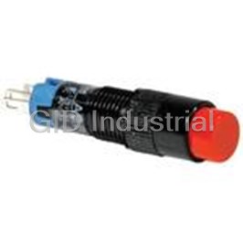
IDEC CORPORATION EB3L-S10SA

Description
Discrete Output Barriers
EB3L-S10SA
Part Number
EB3L-S10SA
Price
Request Quote
Manufacturer
IDEC CORPORATION
Lead Time
Request Quote
Category
Thermal Management » Misc Products
Specifications
Manufacturer
IDEC Corporation
Manufacturers Part #
EB3L-S10SA
Lead Time
5 Week Lead Time
Sub-Categories
Miscellaneous Tools and Supplies
Factory Pack Quantity
1
Datasheet

Extracted Text
�������������� ����� ������������������ ���� ������ Intrinsically Safe Explosion-proof EB3C Relay Barriers EB3L Lamp Barriers Compact housing, low power consumption A variety of control units can be connected. Lamp Barriers Relay Barriers �������������� ����� ������������������ ���� ������ Easy-to-operate Intrinsically Safe Easy-to-operate Intrinsically Safe Lamp Barriers for Worldwide Lamp Barriers for Worldwide Compact and No Grounding Lightweight Required (AC/DC) 198 mm 171.5 mm No grounding required EB3C/EB3L Worldwide Usage (10-circuit) 0.4 kg • Universal AC power voltage (100 to 240V AC) IBRC6101R IBPL610∗E • Compliance with US, Canadian, 1.1 kg European, and Japanese (TIIS) standards 46% footprint, 36% weight. (Compared with IDEC’s IBRC 10-circuit type) Relay Barrier Lamp Barrier 2 140 mm 75 mm �������������� ����� ������������������ ���� ������ Type EB3C Relay Barriers and Type EB3C Relay Barriers and Type EB3L Type EB3L Usage Usage Illuminated Pushbutton/Selector Switches can be used. Illuminated pushbutton/selector switches can be used with the combination of EB3C and EB3L. Dry-contact switches with 0.5Ω maximum contact resistance can be connected to the EB3C. ClassNK Approved for use on ship and other marine structures (Japan). A Variety of Pilot Lights ş6, ş8, ş10, ş22, and ş30 pilot lights can be connected to the EB3L. Super-bright LED is used on ş22 and ş30 pilot lights. Lens colors: Amber, blue, Connector Type Buzzer can be green, red, white, MIL connector on the non-intrinsically and yellow connected to the EB3L safe side. • Easy connection to PLCs Continuous / intermittent buzzer • Wiring is cut by 90% (compared with IDEC’s 16-circuit EB3C). sound available. • Various 20-pin MIL connectors can be connected. Common Wiring for PLC Inputs 8- and 16-circuit types are available in common wiring types, ideal for connection to PLCs. Spring-up Fingersafe Terminals Reduce Wiring Time Spring-up structure Fingersafe Out of touch 3 �������������� ����� ������������������ ���� ������ INTRINSIC SAFETY CONTACT SIGNAL TRANSDUCER EB3C Relay Barrier Input contacts can be used in any explosive gas and Zone 0/Class I Div. 1 areas. Explosion protection Relay Barrier: [Exia] II C Switch: Exia II CT6 or Exia II BT6 • IEC60079 compliant • Dry-contact switches with 0.5Ω maximum contact resistance can be connected to the EB3C. • Compact and lightweight (46% footprint and 36% weight compared to IDEC’s 10-circuit IBRC) • 8- and 16-circuit types are available in common wiring types, ideal for connection to PLCs. 16-circuit types are also avail- able with a connector. • Universal AC power voltage (100 to 240V AC) • No grounding required • IDEC’s original spring-up terminal minimizes wiring time. • Installation 35-mm-wide DIN rail mounting or direct screw mounting • Global usage Connector Type USA: FM Canada:CSA Europe: CE marking, ATEX Japan: TIIS • Ship class: ClassNK (Japan) Types Connection to Number of Power Voltage Non-intrinsically Input Wiring Method Output Type No. Channels Safe Circuit 1 EB3C-R01A 2 EB3C-R02A 3 EB3C-R03A Separate/Common 5 EB3C-R05A Wiring Compatible Relay 6 EB3C-R06A 8 EB3C-R08A 100 to 240V AC 10 EB3C-R10A 8 Common Wiring Only EB3C-R08CA 6 EB3C-T06A Separate/Common 8 Transistor (Sink/Source) EB3C-T08A Wiring Compatible 10 EB3C-T10A Screw Terminal 8 Common Wiring Only Transistor (Sink) EB3C-T08CKA 8 Common Wiring Only EB3C-R08CD Separate/Common 10 Relay EB3C-R10D Wiring Compatible 16 Common Wiring Only EB3C-R16CD Separate/Common 10 Transistor (Sink/Source) EB3C-T10D Wiring Compatible 24V DC 8 EB3C-T08CKD Sink 16 EB3C-T16CKD 8 EB3C-T08CSD Common Wiring Only Transistor Source 16 EB3C-T16CSD Sink EB3C-T16CKD-C 16 Connector Source EB3C-T16CSD-C Accessories Name Type No. Order No. Package Quantity Description BAA1000 BAA1000PN10 10 Aluminum (1 m long) DIN Rail BAP1000 BAP1000PN10 10 Steel (1 m long) BNL5 BNL5PN10 10 For fastening EB3C Mounting Clip BNL6 BNL6PN10 10 units on the DIN rail. 4 �������������� ����� ������������������ ���� ������ EB3C Relay Barrier Explosion-Protection and Electrical SpeciŢcations General Specifications Power Voltage Type AC Power Type DC Power Type Intrinsic safety type Explosion Protection (IEC compliant) [Exia] II C Rated Power Voltage 100 to 240V AC 24V DC Degree of Protection IP20 (IEC60529) Allowable Voltage 85 to 264V AC 21.6 to 26.4V DC Range Safe indoor place Relay Barrier (non-hazardous area) 50/60 Hz (allowable range: Rated Frequency — 47 to 63 Hz) Switch For zone 0, 1, 2 hazardous areas 10A (100V AC) Inrush Current 10A 20A (200V AC) Non-intrinsically Safe Circuit 250V AC 50/60Hz, 250V DC Between intrinsically safe circuit and non-intrinsically Maximum Voltage (Um) safe circuit:1500V AC 1-channel 16-channel Dielectric Strength Wiring Method Between AC power and output terminal: 1500V AC Separate Wiring Common Wiring (1 minute, 1 mA) Between DC power and transistor output terminal: Rated Operating Voltage 12V DC ±10% 1000V AC Rated Operating Current 10 mA DC ±20% Operating Temperature –20 to +60°C (no freezing) Maximum Output Voltage (Uo) 13.2V DC Storage Temperature –20 to +60°C (no freezing) Maximum Output Current (lo) 14.2 mA 227.2 mA Operating Humidity 45 to 85% RH (no condensation) Maximum Output Power (Po) 46.9 mW 750 mW Atmosphere 800 to 1100 hPa Maximum External Inductance (Lo) Pollution Degree 2 (IEC60664) 175 (125) mH 0.68 (0.68) mH (Note) 10 MΩ minimum (500V DC megger, between the same Insulation Resistance Maximum External poles as the dielectric strength) 900 (740) nF Capacitance (Co) (Note) Panel mounting: 10 to 55 Hz, amplitude 0.75 mm Damage Limits 600/(n+1)Ω DIN rail mounting: 10 to 55 Hz, amplitude 0.35 mm (n = number of Allowable Wiring Resistance (Rw) 300Ω Operation common Panel mounting: 10 to 55 Hz, amplitude 0.5 mm channels) Extremes (relay output Maximum Channels per DIN rail mounting: 10 to 55 Hz, amplitude 0.35 mm –16 only) Common Line Contact ConŢguration 1NO 2 Panel mounting: 500 m/s (3 times each on X, Y, Z) Rated Insulation Voltage (Ui) 250V AC, 125V DC Damage Limits Thermal Current (lth) 3A (common terminal: 8A) 2 DIN rail mounting: 300 m/s (3 times each on X, Y, Z) Terminal Style M3 screw terminal Resistive Load AC: 750 VA, DC: 72W Mounting 35-mm-wide DIN rail or panel mounting (M4 screw) Power Consumption 9.6 VA (EB3C-R10A at 200V AC) (approx.) 4.8 W (EB3C-R16CD at 24V DC) AC: 750 VA (cos ş = 0.3 to 0.4) Inductive Load DC: 48W (L/R = 7 ms) Weight (approx.) 0.39 kg (EB3C-R16CD) Switch Explosion-Protection SpeciŢcations (TIIS Japan) Resistive Load 250V AC 3A, 24V DC 3A Simple apparatuses in accordance with relevant standards of each country can be installed in the hazardous area and connected to the EB3C located in the safe area. In Japan, any switches, though regarded as simple apparatuses, must be cer- 250V AC 3A (cos ş = 0.3 to 0.4) Inductive Load tiŢed for explosion-proof devices. EB9Z-A and EB9Z-A1 are IDEC’s generic Type 24V DC 2A (L/R = 7 ms) No. of any single apparatuses certiŢed by TIIS Japan for use with the EB3C, there- Minimum Applicable Load 0.1V DC, 0.1 mA (reference value) fore simple apparatuses with speciŢcations shown below can be used as those Contact Resistance 50 mΩ maximum (initial value) approved by the Japanese explosion-proof certification. Turn ON Time 12 ms maximum (rated voltage) Switch Type No. EB9Z-A EB9Z-A1 Turn OFF Time 10 ms maximum (rated voltage) Explosion Proof Exia II CT6 Exia II BT6 20,000,000 operations minimum Operating Temperature –20 to +60°C (no freezing) Mechanical Life (at 18,000 operations/hour, without Operating Humidity 45 to 85% RH (no condensation) load) Degree of Protection IP20 100,000 operations minimum Electrical Life Dielectric Strength 500V AC, 1 mA (at 1,800 operations/hour, rated load) 1-channel Separate Wiring Short-circuit Protection None Maximum input voltage (Ui): 13.2V Rated Voltage 24V DC Maximum input current (Ii): 14.2 mA Maximum Voltage 30V DC Maximum input power (Pi): 46.9 mW Internal inductance (Li): ≤ 5 µH Maximum Current 100 mA (connector type: 15 mA) Intrinsic Safety Ratings Internal capacitance (Ci): ≤ 2 nF Leakage Current 0.1 mA maximum and Parameters 16-channel Common Wiring Voltage Drop 1V maximum Maximum input voltage (Ui): 13.2V Clamping Voltage 33V (1W) Maximum input current (Ii): 227.2 mA Maximum input power (Pi): 750 mW Inrush Current 0.5A maximum (1 sec) Internal inductance (Li): ≤ 80 µH Turn ON Time 0.1 ms maximum (resistive load) Internal capacitance (Ci): ≤ 32 nF Turn OFF Time 0.4 ms (typical) (resistive load) Metallic: Magnesium content must be 6% or less Short-circuit Protection None (steel and aluminum are acceptable) Note: Values in ( ) are those approved by TIIS (Technology Institution of Plastic: Switch operator Caution Industrial Safety, Japan). exposed area To prevent electrostatic 2 IIC: 20 cm maximum charges, do not rub the Enclosure Material 2 Certification No. IIB: 100 cm maximum switch surface during operation. Use a soft When the switch has a CertiŢcation cloth dipped with water Explosion Protection CertiŢcation No. wider exposed area, attach Organization for cleaning. a caution label as shown at Class I, II, III Div. 1 right. Caution Label Example 3015417 (terminal type) Group A, B, C, D, E, F, G FM 3019223 (connector type) Contact rating: Ui, Ii minimum Class I, Zone 0 AEx [ia] IIC Contact resistance: 0.5Ω maximum 2 CSA Class I Div. 1 Group A, B, C, D 166730 Cross sectional area of wire: 0.000962 mm maximum Printed circuit board: Thickness 0.5 mm minimum NEMKO [EExia] II C Nemko 02ATEX279 Copper foil width 0.15 mm Relay barrier: [Exia] II C C15753 Switch Ratings minimum TIIS Japan Switch (EB9Z-A): Exia II CT6 C15758 Thickness 18 µm minimum one/ Switch (EB9Z-A1): Exia II BT6 C15961 both side(s) A resistor to prevent contact welding and an LED can be ClassNK Exia II C 02T606 connected to 1-channel separate wiring circuits. Consult Note: For details about switches, see “Switch Explosion-Protection SpeciŢca- IDEC for details. tions” on page 5 and “3. Switches in the Hazardous Area” on page 9. Note: For details, see “3. Switches in the Hazardous Area” on page 9. 5 Installation Non-intrinsically Safe Circuits Intrinsically Safe Circuits Location Transistor Output Relay Output Contact Rated Load Allowable Power Shock Vibration Resistance Resistance �������������� ����� ������������������ ���� ������ AS-Interface Components EB3C Relay Barrier Internal Circuit Block Diagram • AC Power, Relay Output Type • DC Power, Transistor Output Type • Connector Wiring, Sink Output Type Hazardous Area •• • • •• • • P1 N1 P2 N2 P3 N3 P1 •• • • P16 N1 N2 P1 N1 P2 N2 P3 N3 Non-hazardous Area Yellow Yellow Yellow Yellow Yellow Yellow Yellow Yellow Green Green Green ~ ~ ~ ~ ~ ~ ~ •• • • L N A1 C1A2C2A3C3 + – A1 C1 A2 C2 A3 C3 + – A1 A16 C1 C2 Dimensions • Screw Terminal Type EB3C–∗08 EB3C–∗05 EB3C–∗10 EB3C–∗02 EB3C–∗06 EB3C–∗16C EB3C–∗03 EB3C–∗01 EB3C–∗08C 42 65 110.5 171.5 77.5 ş6 hole 10 10 10 10 10 Mounting Hole Layout (Screw Mounting) 2-M4 tapped or 2-M4 tapped or 2-M4 tapped or 4-M4 tapped or 2-ş4.5 mounting 2-ş4.5 mounting holes 2-ş4.5 mounting holes 4-ş4.5 mounting holes holes 28 51 97 97 • Connector Type 171.5 Applicable Crimping Terminal ş3 min. 3 max. 5.4 min. 4-M4 or 4-ş4.5 holes Stripping the Wire End 83.5 97 Solid Wire Mounting Hole Layout 6 to 8 mm Stranded Wire (Ferrule) 6 to 8 mm 10 10 97 All dimensions in mm. 6 ş6 77.5 (4) 6 75 6 65 4 61 77.5 75 4- 4.5 holes 65 65 65 6 max. (4) ş4.4 65 ������������������ ���������������������������� EB3C Relay Barrier External Wiring Examples • Transistor Sink Output Type (Ex.: EB3C-T08CKD) • Transistor Source Output Type (Ex.: EB3C-T08CSD) P1 P2 P3 P4 P5 P6 P7 P8 N1 N2 P1 P2 P3 P4 P5 P6 P7 P8 N1 N2 +– A1 A2 A3 A4 A5 A6 A7 A8 C1 C2 + – A1 A2 A3 A4 A5 A6 A7 A8 C1 C2 Load Power Load Power 24V DC 24V DC 24V DC 24V DC • Relay Output Type (Ex.: EB3C-R06A) • Transistor Output Type (Ex.: EB3C-T06A) P1 N1 P2 N2 P3 N3 P4 N4 P5 N5 P6 N6 P1 N1 P2 N2 P3 N3 P4 N4 P5 N5 P6 N6 L N A1 C1 A2 C2 A3 C3 A4 C4 A5 C5 A6 C6 L N A1 C1 A2 C2 A3 C3 A4 C4 A5 C5 A6 C6 Load AC Power AC Power Power Load AC/DC Power 24V DC Connector Type Output Wiring Diagram • EB3C-T16CKD-C Wiring Example with IDEC’s PLC MicroSmart CH9 CH10 CH11 CH12 CH13 CH14 CH15 CH16 EB3C-T16CKD-C FC4A-N16B3 EB3C-T16CSD-C FC4A-N16B3 A9 A10 A11 A12 A13 A14 A15 A16 NC NC Terminal Output Input Terminal Terminal Output Input Terminal CHn 19 1 20 A1 I0 20 20 A1 I0 20 20 2 – + An COM 19 A9 I10 19 19 A9 I10 19 A1 A2 A3 A4 A5 A6 A7 A8 C1 C2 18 A2 I1 18 18 A2 I1 18 CH1 CH2 CH3 CH4 CH5 CH6 CH7 CH8 +V COM 17 A10 I11 17 17 A10 I11 17 16 A3 I2 16 16 A3 I2 16 • EB3C-T16CSD-C 15 A11 I12 15 15 A11 I12 15 CH10 CH11 CH12 CH13 CH14 CH15 CH16 CH9 A9 A10 A11 A12 A13 A14 A15 A16 NC NC 14 A4 I3 14 14 A4 I3 14 CHn 19 1 13 A12 I13 13 13 A12 I13 13 20 2 + – 12 A5 I4 12 12 A5 I4 12 A2 A3 A4 A5 A6 A7 A8 C1 C2 A1 An COM CH2 CH3 CH4 CH5 CH6 CH7 CH8 –V COM 11 A13 I14 11 11 A13 I14 11 CH1 10 A6 I5 10 10 A6 I5 10 9 A14 I15 9 9 A14 I15 9 8 A7 I6 8 8 A7 I6 8 7 A15 I16 7 7 A15 I16 7 6 A8 I7 6 6 A8 I7 6 5 A16 I17 5 5 A16 I17 5 4 +V COM 4 4 –V COM 4 3 NC COM 3 3 NC COM 3 2 COM(–) NC 2 2 COM(+) NC 2 1 NC NC 1 1 NC NC 1 Note 1: The wiring in dashed line does not affect the operation of the MicroSmart. Note 2: Applicable connector is IDEC’s JE1S-201. 7 Load Load Load Load Load Load Load Load Load Load Load Load Load Load Load Load Load Load Load Load Load Load Load Load Load Load Load Load 100 �������������� ����! ������������������ ���� ������ AS-Interface Components EB3C Relay Barrier Wiring 1. Separate Wiring Diagram Symbols • Each input line of the EB3C makes up one independent intrinsically safe circuit. Contacts in one switch (EB9Z-A or EB9Z-A1) One intrinsically safe circuit (16 circuits maximum) EB3C-∗01 EB3C-∗03 EB3C-∗06 EB3C-∗10 2. Common Wiring (Maximum 16 cicuits) • All input lines are wired to a common line inside the intrinsically safe switch (one common line per intrinsically safe circuit). EB3C-∗16C EB3C-∗01 EB3C-∗03 EB3C-∗06 EB3C-∗10 EB3C-∗08C • Some input lines are wired to a common line inside the intrainsically safe switches, while others are outside the switches (one common line per intrinsically safe circuit). EB3C-∗16C EB3C-∗01 EB3C-∗03 EB3C-∗06 EB3C-∗10 EB3C-∗08C • All input lines are wired to a common line outside the intrinsically safe switches (one common line per intrinsically safe circuit). EB3C-∗16C EB3C-∗01 EB3C-∗03 EB3C-∗06 EB3C-∗10 EB3C-∗08C Recommended Connector Cable for Connector Types Description No. of Poles Length (m) Type No. Appearance Applicable Type 0.5 FC9Z-H050A20 1 FC9Z-H100A20 With Shield MicroSmart I/O Module 2 FC9Z-H200A20 3 FC9Z-H300A20 0.5 FC9Z-H050B20 1 FC9Z-H100B20 Without Shield MicroSmart I/O Module 2 FC9Z-H200B20 3 FC9Z-H300B20 20 1 BX9Z-H100E4 200 Cable with Crimping 2 BX9Z-H200E4 Screw Terminal Type 2 Terminal 1 3 BX9Z-H300E4 Mitsubishi A, Q Series 350 1 BX9Z-H100L Input Module (positive common) 40-pin Cable for PLC 2 BX9Z-H200L ↓ 3 BX9Z-H300L EB3C-T16CKD-C 8 I/O Terminal Cable L L L L N N N N A1 P1 A1 P1 A1 P1 A1 P1 A2 P2 C1 N1 A2 P2 A2 P2 A3 P3 A3 P3 A3 P3 C2 N2 A4 P4 A4 P4 A4 P4 A5 P5 L A5 P5 A5 P5 A6 P6 A6 P6 N A6 P6 A7 P7 A1 P1 A7 P7 A7 P7 A8 P8 C1 N1 A8 P8 A8 P8 C1 N1 C1 N1 A2 P2 C1 N1 C2 N2 C2 N2 C2 N2 C2 N2 A3 P3 A9 P9 A9 P9 A9 P9 A10 P10 A10 P10 C3 N3 A10 P10 A11 P11 A11 P11 A11 P11 L A12 P12 A12 P12 A12 P12 A13 P13 A13 P13 N A13 P13 A14 P14 A1 P1 A14 P14 A14 P14 A15 P15 A15 P15 A15 P15 C1 N1 A16 P16 A2 P2 A16 P16 A16 P16 C3 N3 C2 N2 C3 N3 C3 N3 C4 N4 C4 N4 A3 P3 C4 N4 C3 N3 L A4 P4 L L N N C4 N4 N A1 P1 A5 P5 A1 P1 A1 P1 C5 N5 C1 N1 C1 N1 C1 N1 C2 N2 C2 N2 A6 P6 C2 N2 C6 N6 L L L N N L N A1 P1 N A1 P1 A1 P1 C1 N1 C1 N1 C1 N1 A1 P1 A2 P2 C1 N1 A2 P2 A2 P2 C2 N2 A2 P2 C2 N2 C2 N2 A3 P3 A3 P3 C2 N2 A3 P3 C3 N3 A3 P3 C3 N3 C3 N3 C3 N3 L L A4 P4 L N C4 N4 N N A5 P5 A1 P1 A1 P1 A1 P1 C1 N1 C1 N1 C5 N5 C1 N1 A2 P2 A6 P6 A2 P2 A2 P2 C6 N6 C2 N2 C2 N2 C2 N2 A3 P3 A3 P3 A7 P7 A3 P3 C3 N3 C7 N7 C3 N3 C3 N3 A4 P4 A4 P4 A4 P4 A8 P8 C4 N4 C8 N8 C4 N4 C4 N4 A5 P5 A9 P9 A5 P5 A5 P5 C5 N5 C5 N5 C9 N9 C5 N5 A6 P6 A10 P10 A6 P6 A6 P6 C6 N6 C10 N10 C6 N6 C6 N6 L L L N N N A1 P1 A1 P1 A1 P1 C1 N1 C1 N1 C1 N1 A2 P2 A2 P2 A2 P2 C2 N2 C2 N2 C2 N2 A3 P3 A3 P3 A3 P3 C3 N3 C3 N3 C3 N3 A4 P4 A4 P4 A4 P4 C4 N4 C4 N4 C4 N4 A5 P5 A5 P5 A5 P5 C5 N5 C5 N5 C5 N5 A6 P6 A6 P6 A6 P6 C6 N6 C6 N6 C6 N6 A7 P7 A7 P7 A7 P7 C7 N7 C7 N7 C7 N7 A8 P8 A8 P8 A8 P8 C8 N8 C8 N8 C8 N8 A9 P9 A9 P9 A9 P9 C9 N9 C9 N9 C9 N9 A10 P10 A10 P10 A10 P10 C10 N10 C10 N10 C10 N10 L L L N N N A1 P1 A1 P1 A1 P1 A2 P2 A2 P2 A2 P2 A3 P3 A3 P3 A3 P3 A4 P4 A4 P4 A4 P4 A5 P5 A5 P5 A5 P5 A6 P6 A6 P6 A6 P6 A7 P7 A7 P7 A7 P7 A8 P8 A8 P8 A8 P8 C1 N1 C1 N1 C1 N1 C2 N2 C2 N2 C2 N2 �������������� ����" ������������������ ���� ������ EB3C Relay Barrier Precautions for Operation 1. Installation of EB3C Relay Barriers 3. Switches in the Hazardous Area (For Japan application only) (1) The EB3C can be installed in any direction. (1) A switch contains the switch contact, enclosure, and inter- (2) Install the EB3C relay barrier in a safe area (non-hazardous nal wiring. A switch contact refers to an ordinary switching area) in accordance with intrinsic safety ratings and param- device which consists of contacts only, such as a pushbut- eters. To avoid mechanical shocks, install the EB3C in an ton switch. See below. enclosure which suppresses shocks. Applicable Switches (3) When installing or wiring the EB3C, prevent electromag- netic and electrostatic inductions in the intrinsically safe cir- Push-pull Switches Pushbutton, Foot, Trigger, Rocker, Grip cuit. Also prevent the intrinsically safe circuits from Rotary, Selector, Cam, Drum, Thumb Control Twisting Switches contacting with another intrinsically safe circuit and any wheel Switches other circuits. Lever and Slide Toggle, Multidirectional, Wobble stick, Switches Lever, Slide switch Maintain at least 50 mm clearance, or provide a metallic Displacement Microswitch, Limit, Magnetic proximity, separating board between the intrinsically safe circuit and Switches Door, Reed, Mercury non-intrinsically safety circuit. When providing a metallic Sensing Switches Level Switches Liquid level separating board, make sure that the board Ţts closely to the enclosure (top, bottom, and both sides). Allowable Others Pressure, Temperature clearance between the enclosure and board is 1.5 mm at Note: For installation in hazardous areas and connection to the EB3C, use the maximum. switches which are certiŢed, approved, or considered to be simple apparatus in relevant standards in each country. The clearance of 50 mm between the intrinsically safe cir- cuit and non-intrinsically safe circuit may not be sufŢcient (2) When the switch has internal wiring or lead wire, make sure when a motor circuit or high-voltage circuit is installed that the values of internal inductance (Li) and capacitance nearby. In this case, provide a wider clearance between the (Ci) are within the certiŢed values. circuits referring to 5 (3) “Minimum Parallel Distance (3) Enclose the switch contact’s bare live part in an enclosure between the Intrinsically Safe Circuit and Other Circuits.” of IP20 or higher protection. (4) In order to prevent contact between intrinsically safe circuits (4)Depending on the explosion-protection speciŢcations and non-intrinsically safe circuits, mount EB3C units with according to TIIS Japan, the exposed area of plastic switch terminals arranged in the same direction. operator is limited as follows: 2 Intrinsically Safe Circuit • Exia II CT6 (EB9Z-A): 20 cm maximum 2 • Exia II BT6 (EB9Z-A1): 100 cm maximum EB3C EB3C EB3C (5) Attach the certiŢcation mark supplied with the EB3C on the Non-intrinsically Safe Circuit EB9Z-A or EB9Z-A1 switch (for Japan application). (6) Magnesium content of metallic enclosure must be 6% or EB3C EB3C less (steel and aluminum are acceptable). (7) When the switch operator of plastic enclosure has a wider Intrinsically Safe Circuit exposed area than the following limits, attach a caution label as shown below. (5) Maintain at least 6 mm (or 3 mm according to IEC60079- 2 Caution IIC: 20 cm maximum 11: 1999) clearance between the terminal of intrinsically To prevent electrostatic 2 safe circuit and the grounded metal part of a metal enclo- IIB: 100 cm maximum charges, do not rub the switch surface during operation. sure, and between the relay terminal block of an intrinsically Use a soft cloth dipped with safe circuit and the grounded metal part of a metal enclo- water for cleaning. sure. Caution Label Example (6) For installing the EB3C, mount on a 35-mm-wide DIN rail or directly on a panel using screws. Make sure to install (8) For the 1-circuit separate wiring, a resistor to prevent reed securely to withstand vibration. When mounting on a DIN switch contact welding and an LED miniature pilot lights rail, push in the clamp completely. Use the BNL5 or BNL6 can be connected in series with the contact. See below. mounting clips on both sides of the EB3C to prevent from Use the terminal screw of M3 or larger. moving sideways. (7) Excessive extraneous noise may cause malfunction and Applicable Resistor Ratings damage to the EB3C. When extraneous noise activates the Resistance 100Ω maximum voltage limiting circuit (thyristor), remove the noise source Rated Wattage 0.5 to 3W and restore the power. Type Metal (oxide) Ţlm resistors 2. Terminal Wiring R (1) Using a ş5.5 mm or smaller screw driver, tighten the termi- nal screws (including unused terminal screws) to a torque Reed Switch of 0.6 to 1.0 N·m (recommended value). (2) Make sure that IP20 is achieved when wiring. Use insula- tion tubes on bare crimping terminals. (3) To prevent disengaged wires from contacting with other intrinsically safe circuits, bind together the wires of one intrinsically circuit. EB3C (4) When the adjacent terminal is connected to another intrinsi- • Applicable LED Type cally safe circuit, provide an insulation distance of at least 6 IDEC’s IPL1 series LED miniature pilot lights. mm. 9 �������������� ������ ���������������������� ������ AS-Interface Components EB3C Relay Barrier Precautions for Operation 4. Output SpeciŢcations 5. Wiring for Intrinsic Safety (1) When wiring the output from the EB3C, connect the non- (1) The voltage applied on the general circuit connected to the intrinsically safe circuit to terminals A and C. The EB3C out- non-intrinsically safe circuit terminals of the EB3C relay bar- put circuit is not equipped with short-circuit protection. If rier must be 250V AC, 50/60Hz, or 250V DC at the maxi- required, provide a protection in the external circuit. mum under any conditions, including the voltage of the input power and the internal circuit. (2) Relay Output (2) When wiring, take into consideration the prevention of elec- Some types of loads generate reverse emf (such as sole- tromagnetic and electrostatic charges on intrinsically safe noids) or cause a large inrush current (incandescent circuits. Also, prevent intrinsically safe circuits from contact- lamps), resulting in a shorter operation life of output relay ing with other circuits. contacts. The operation life of contacts can be extended by preventing the reverse emf using a diode, RC, or varistor, or (3) The intrinsically safe circuits must be separated from non- by suppressing the inrush current using a resistor or RL. intrinsically safe circuits. Contain intrinsically safe circuits in a metallic tube or duct, or separate the intrinsically safe cir- Contacts are made of gold-clad silver. When using at a cuits referring to the table below. small current and a low voltage (reference value: 0.1 mA, Note: Cables with a magnetic shield, such as a metallic sheath, prevent elec- 0.1V), test the contact on the actual circuit in advance. tromagnetic induction and electrostatic induction, however, a non- (3) Transistor Output magnetic shield prevents electrostatic induction only. For non-mag- netic shields, take a preventive measure against electromagnetic When connecting a small load, the load may not turn off induction. because of a leakage current, even though the transistor output is turned off. If this is the case, connect a resistor in Finely twisted pair cables prevent electromagnetic induc- parallel with the load to bypass the leakage current. tion. Adding shields to the twisted pair cables provides pro- tection against electrostatic induction. When an excessively high voltage (clamps at 33V, 1W) or a reverse voltage is applied to the output terminals, the Minimum Parallel Distance between the Intrinsically clamping circuit or output transistor may be damaged. Safe Circuit and Other Circuits (mm) When driving an inductive load, be sure to connect a diode Voltage and across the load to absorb reverse emf. Current of Other Over 100A 100A or less 50A or less 10A or less Circuits Over 440V 2000 2000 2000 2000 440V or less 2000 600 600 600 An Load 220V or less 2000 600 600 500 110V or less 2000 600 500 300 * 60V or less 2000 500 300 150 Cn (4) When identifying intrinsically safe circuits by color, use light : Surge Absorber * blue terminal blocks and cables. Example of Overvoltage Absorption Circuit (5) When using two or more EB3C’s to set up one intrinsically safe circuit in the common wiring conŢguration, intercon- nect two neutral terminals (N1 through N10) on each EB3C (4) In the common wiring only types, the output terminals are between adjacent EB3C’s in parallel. not isolated from each other. (6) Make sure that the power of the EB3C and contact are (5) When connecting the connector type EB3C’s in parallel, turned off before starting inspection or replacement. use one power supply to power the EB3C’s. Do not connect Note: For the details of wiring the intrinsically safe circuits, refer to a relevant any wiring to the C1 and C2 terminals. test guideline for explosion-proof electric equipment in each country. 10 �������������� ������ ���������������������� ������ INTRINSIC SAFETY LAMP BARRIER EB3L Lamp Barrier 120 types of pilot lights and buzzers can be connected. Illuminated pushbuttons and illuminated selector switches can be connected by combining with the EB3C relay barrier. No grounding required. Explosion protection Lamp Barrier [Exia] II C Pilot Light (separate wiring) Exia II CT6 Pilot Light (common wiring) Exia II CT4 Illuminated Pushbutton Exia II CT4 Illuminated Selector Switch Exia II CT4 Buzzer (separate wiring) Exia II CT6 • IEC60079 compliant • Compact and lightweight (46% footprint and 36% weight com- pared to IDEC’s 10-circuit IBPL) • 8- and 16-circuit types are available in common wiring types, ideal for connection to PLCs. 16-circuit types are also available with a connector. • Universal AC power voltage (100 to 240V AC) • No grounding required Connector Type • IDEC’s original spring-up terminal minimizes wiring time. • Installation 35-mm-wide DIN rail mounting or direct screw mounting • ş6, ş8, ş10, ş22 and ş30 pilot lights available • Illuminated pushbuttons and illuminated selector switches can be connected by combining with the EB3C relay barrier. Illumination colors: Amber, blue, green, red, white, and yellow (pushlock turn reset type: red only) • Continuous and intermittent sound types are available for buzz- ers (ş30). • Global usage USA: FM Canada: CSA Europe: CE marking, ATEX Japan: TIIS • Ship class: ClassNK (Japan) Types Connection to Number of Power Voltage Non-intrinsically Input Wiring Method Output Type No. Channels Safe Circuit 1 EB3L-S01SA 2 EB3L-S02SA 3 Source EB3L-S03SA Separate/Common 100 to 240V AC 6 Wiring Compatible EB3L-S06SA EB3L-S10SA 10 Screw Terminal Sink EB3L-S10KA 8 Common Wiring Only Transistor EB3L-S08CSD Separate/Common 10 Source EB3L-S10SD Wiring Compatible EB3L-S16CSD 24V DC Sink EB3L-S16CKD 16 Common Wiring Only Source EB3L-S16CSD-C Connector Sink EB3L-S16CKD-C Accessories Name Type No. Order No. Package Quantity Description BAA1000 BAA1000PN10 10 Aluminum (1 m long) DIN Rail BAP1000 BAP1000PN10 10 Steel (1 m long) BNL5 BNL5PN10 10 For fastening EB3L Mounting Clip BNL6 BNL6PN10 10 units on the DIN rail. 11 �������������� ������ ���������������������� ������ AS-Interface Components EB3L Lamp Barrier • Pilot Lights, Illuminated Pushbuttons, Illuminated Selector Switches, and Buzzers Lens Color/ Series Type Size Shape Operation Mode Contact Type No. (Note 2) Illumination Operation (Note 1) Color Code∗ Dome — — EB3P-LAN1-∗ Dome w/Diecast ş30 N — — EB3P-LAD1-∗ Sleeve Square — — EB3P-LUN3B-∗ Flush — — EB3P-LAW1-∗ Flush — — EB3P-LAW1B-∗ A: Amber (Marking Type) TW G: Green Dome — — EB3P-LAW2-∗ R: Red Square Flush — — — EB3P-LUW1B-∗ S: Blue (Marking Type) W: White Round Flush — — EB3P-LHW1-∗ ş22 Y: Yellow HW Dome — — EB3P-LHW2-∗ Square Flush — — EB3P-LHW4-∗ Round — — EB3P-LLW1-∗ Square — — EB3P-LLW2-∗ LW Round w/Square — — EB3P-LLW3-∗ Bezel Extended — — IPL1-18-∗ ş10 Coned — — IPL1-19-∗ A: Amber Flush — — IPL1-87-∗ G: Green ş8 Extended — — IPL1-88-∗ UP R: Red — Coned — — IPL1-89-∗ W: White Flush — — IPL1-67-∗ Y: Yellow ş6 Extended — — IPL1-68-∗ Coned — — IPL1-69-∗ A: Amber Momentary 1NO-1NC EB3P-LBAN211-∗ G: Green R: Red Extended S: Blue ş30 N Maintained 1NO-1NC EB3P-LBAON211-∗ W: White Y: Yellow Mushroom Pushlock Turn Reset 1NO-1NC EB3P-LBAVN311-R R A: Amber Momentary 1NO-1NC EB3P-LBAW211-∗ G: Green R: Red Extended — TW S: Blue Maintained 1NO-1NC EB3P-LBAOW211-∗ W: White Y: Yellow Mushroom Pushlock Turn Reset 1NO-1NC EB3P-LBAVW411-R R ş22 Momentary 1NO EB3P-LBH1W110-∗ HW Round Maintained 1NO EB3P-LBHA1W110-∗ Momentary DPDT EB3P-LBL1W1C2-∗ Round Maintained DPDT EB3P-LBLA1W1C2-∗ LW Momentary DPDT EB3P-LBL2W1C2-∗ Square Maintained DPDT EB3P-LBLA2W1C2-∗ 2-position 1NO-1NC EB3P-LSAN211-∗ Maintained ş30 N Round 3-position 2NO EB3P-LSAN320-∗ Maintained 2-position 1NO-1NC EB3P-LSAW211-∗ Maintained A: Amber 2-position, G: Green 1NO-1NC EB3P-LSAW2111-∗ Spring return from right return from right R: Red 3-position 2NO EB3P-LSAW320-∗ Maintained S: Blue 3-position, W: White TW Round 2NO EB3P-LSAW3120-∗ Spring return from right return from right Y: Yellow 3-position, 2NO EB3P-LSAW3220-∗ Ring return from left return from left ş22 3-position, 2NO EB3P-LSAW3320-∗ 2-way spring return 2-way return 2-position 1NO-1NC EB3P-LSHW211-∗ Maintained HW Round 3-position 2NO EB3P-LSHW320-∗ Maintained Round 2-position DPDT EB3P-LSL1W2C2-∗ Maintained LW Round w/Square 3-position DPDT EB3P-LSL3W3C2-∗ Maintained Bezel Continuous sound — EB3P-ZUN12C — Buzzer ş30 — — — Intermittent sound — EB3P-ZUN12F — Note 1: Codes N, TW, HW, LW, and UP are the series names of IDEC’s control units. Note 2: Specify a color code in place of ∗. Note 3: Illuminated selector switches have a knob operator. Accessories Name Type No. Package Quantity LED Lamp EB9Z-LDS1-∗ 1 Note: Specify a color code in place of ∗ in the Type No. A: amber, G: green, R: red, S: blue, W: white, Y: yellow 12 Illuminated Selector Switch Illuminated Pushbutton Miniature Pilot Light Pilot Light (Note 3) �������������� ������ ���������������������� ������ EB3L Lamp Barrier Explosion-Protection and Electrical SpeciŢcations General SpeciŢcations of Pilot Light, Illuminated Pushbutton, Illuminated Selector Switch, and Buzzer Intrinsic safety type Explosion Protection (IEC compliant) [Exia] II C Operating Temperature –20 to +60°C (no freezing) Degree of Protection IP20 (IEC60529) Operating Humidity 45 to 85% RH (no condensation) Lamp Barrier Safe indoor place (non-hazardous area) EB3P: 1000V AC Dielectric Strength IPL1: 500V AC (1 mA, 1 minute) Pilot Light, Illuminated Switch, (between intrinsically safe circuit and dead parts) For zone 0, 1, 2 hazardous areas Buzzer 10 MΩ minimum (500V DC megger, between the Insulation Resistance same poles as the dielectric strength) Non-intrinsically Safe Circuit 250V AC 50/60Hz, 250V DC Maximum Voltage (Um) IP65 (IEC60529) (except for terminals) Degree of Protection EB3P-LU/IPL1: IP40 Operation Input ON, Output ON (1:1) 1-channel 16-channel Lens/Illumination Pilot light: Amber, blue, green, red, white, yellow Wiring Method Color Miniature pilot light: Amber, green, red, white, yellow Separate Wiring Common Wiring Rated Operating Voltage 12V DC 1-channel Separate Wiring Maximum input voltage (Ui): 13.2V Rated Operating Current 10 mA DC Maximum input current (Ii): 14.2 mA Maximum Output Voltage (Uo) 13.2V DC Maximum input power (Pi): 46.9 mW Internal inductance (Li): ≤ 5 µH Maximum Output Current (lo) 14.2 mA 227.2 mA Intrinsic Safety Internal capacitance (Ci): ≤ 2 nF Ratings and Maximum Output Power (Po) 46.9 mW 750 mW 16-channel Common Wiring Parameters Maximum input voltage (Ui): 13.2V Maximum External Inductance 125 mH 0.68 mH (Lo) (Note) Maximum input current (Ii): 227.2 mA Maximum input power (Pi): 750 mW Maximum External 740 nF Internal inductance (Li): ≤ 80 µH Capacitance (Co) (Note) Internal capacitance (Ci): ≤ 32 nF 200/(n+1)Ω Allowable Wiring Resistance (Rw) IP65 (IEC60529) (except for terminals) (n = number of common channels) Degree of Protection EB3P-LSAW∗∗: IP54 Maximum Channels per 16 Illumination Color Amber, blue, green, red, white, yellow Common Line Contact 12V DC ±10%, 10 mA ±20% Pilot light: 3.5V, 8.5 mA Voltage/Current (when connecting to the EB3C) Voltage and Current when Miniature pilot light: 2V, 10 mA Connecting Control Units Illuminated switch: 3.5V, 8.5 mA 16-channel Common Wiring Buzzer: 6.5V, 5.5 mA Maximum input voltage (Ui): 13.2V Intrinsic Safety Maximum input current (Ii): 227.2 mA Rated voltage: 24V DC Ratings and Non-intrinsically Safe Circuits Maximum input power (Pi): 750 mW Rated current: 5 mA Parameters (Signal Input) Internal inductance (Li): ≤ 80 µH (connector type: 4 mA) Internal capacitance (Ci): ≤ 32 nF Degree of Protection IP20 (IEC60529) (except for terminals) General Specifications Sound Volume 75 dB minimum (at 1 m) Power Voltage Type AC Power Type DC Power Type Sound Source Piezoelectric oscillator (continuous or intermittent) Rated Power Voltage 100 to 240V AC 24V DC 1-channel Separate Wiring Allowable Voltage Maximum input voltage (Ui): 13.2V 85 to 264V AC 21.6 to 26.4V DC Intrinsic Safety Range Maximum input current (Ii): 14.2 mA Ratings and Maximum input power (Pi): 46.9 mW 50/60 Hz (allowable range: Rated Frequency — Parameters 47 to 63 Hz) Internal inductance (Li): ≤ 100 mH Internal capacitance (Ci): ≤ 260 nF 10A (100V AC) Inrush Current 10A 20A (200V AC) Note: Connect buzzers in separate wring. Buzzers cannot be used in com- mon wiring. Between intrinsically safe circuit and non-intrinsically Dielectric Strength safe circuit:1500V AC (1 minute, 1 mA) Certification No. Between AC power and signal input: 1500V AC CertiŢcation CertiŢcation Operating Temperature –20 to +60°C (no freezing) Type Explosion Protection Organization No. Storage Temperature –20 to +60°C (no freezing) Class I, II, III Div. 1 Operating Humidity 45 to 85% RH (no condensation) Group A, B, C, D, E, F, G Lamp Barrier Class I, Zone 0 AEx [ia] IIC Atmosphere 800 to 1100 hPa 3019223 FM Class I, II, III Div. 1 Pollution Degree 2 (IEC60664) Group A, B, C, D, E, F, G 10 MΩ minimum (500V DC megger, between the same Buzzer Insulation Resistance T6 poles as the dielectric strength) Class I, Zone0 AExiaIICT6 Panel mounting: 10 to 55 Hz, amplitude 0.75 mm Class I Div. 1 (2 hours each on X, Y, Z) Lamp Barrier 166730 Group A, B, C, D Damage Limits CSA DIN rail mounting: 10 to 55 Hz, amplitude 0.35 mm Class I Div. 1 (2 hours each on X, Y, Z) Buzzer Group A, B, C, D T6 2 Panel mounting: 500 m/s (3 times each on X, Y, Z) Nemko Lamp Barrier [EExia] II C 02ATEX279 Damage Limits NEMKO 2 Nemko DIN rail mounting: 300 m/s (3 times each on X, Y, Z) Buzzer Exia IICT6 03ATEX1628X Terminal Style M3 screw terminal Lamp barrier [Exia] II C C16355 Mounting 35-mm-wide DIN rail or panel mounting (M4 screw) Pilot light/miniature pilot light Exia II CT6 C16361 Power Consumption 8.8 VA (EB3L-S10SA at 200V AC) (separate wiring) (approx.) 5.2 W (EB3L-S16CSD at 24V DC) TIIS Japan Pilot light/miniature Weight (approx.) 0.35 kg (EB3L-S16CSD) pilot light Exia II CT4 C16360 (common wiring) Illuminated switch Exia II CT4 C16362 Buzzer Exia II CT6 C16363 Lamp barrier Exia II C 02T606 ClassNK Buzzer Exia II CT6 04T605 Note: Illuminated switches, pilot lights, and miniature pilot lights are certiŢed by TIIS Japan and NK Japan only. FM, CSA, and NEMKO regard these units as simple apparatus, and require no certiŢcation. 13 Installation Shock Vibration Intrinsically Safe Circuits (Output) Resistance Resistance Location Buzzer Illuminated Switch Pilot light/Miniature Pilot Light �������������� ������ ���������������������� ������ AS-Interface Components EB3L Lamp Barrier Internal Circuit Block Diagram AC Power DC Power Connector Wiring Source Input Type Sink Input Type Source Input Type Hazardous Area P1 N1 P2 N2 P3 N3 P1 N1 P2 N2 P3 N3 P1 • • • • P16 N1 N2 Non-hazardous Area Yellow Yellow Yellow Yellow Yellow Yellow Yellow Yellow Green Green Green – – – – – – ~ ~ – ~ ~ ~ ~ ~ +– – +– + +– – +– + L N S1 C1S2C2S3C3 + – S1 C1 S2 C2 S3 C3 + – S1 • • • • S16 C1 C2 Allowable Inductance/Capacitance for Intrinsically Safe External Wiring Keep the inductance (Lw) and capacitance (Cw) for the external wiring in the intrinsically safe circuit as shown below: Lw ≤ Lo – Li, Cw ≤ Co – Ci where Lo is the maximum external inductance, Li is the internal inductance, Co is the maximum external capacitance, and Ci is the internal capacitance. Dimensions • Terminal Type EB3L–S06 EB3L–S02 EB3L–S10 Intrinsic Safety Side: EB3L–S01 EB3L–S08C EB3L–S03 EB3L–S16C Light Blue 42 65 110.5 171.5 77.5 ş6 hole Non-Intrinsic Safety Side: Yellow 10 10 10 10 10 Mounting Hole Layout (Screw Mounting) 2-M4 tapped or 2-M4 tapped or 4-M4 tapped or 2-ş4.5 mounting 2-M4 tapped or 2-ş4.5 mounting holes 4-ş4.5 mounting holes 2-ş4.5 mounting holes holes 28 51 97 97 • Connector Type 171.5 Applicable Crimping Termin ş3 min. 3 max. 5.4 min. 4-M4 or 4-ş4.5 holes Stripping the Wire End Solid Wire 83.5 97 Mounting Hole Layout 6 to 8 mm Stranded Wire (Ferrule) 6 to 8 mm 10 10 All dimensions in mm. 97 14 ş6 77.5 (4) 75 6 6 65 4 61 77.5 75 4- 4.5 holes 65 65 65 6 max. (4) 65 LOCK LOCK LOCK �������������� ������ ���������������������� ������ EB3L Lamp Barrier • Pilot Lights ş30 EB3P-LAN1 ş30 EB3P-LAD ş30 EB3P-LUN3B M3 Terminal M3.5 Terminal Panel Thickness 0.8 to 5.5 Screw Panel Thickness 0.8 to 7.5 Screw Panel Thickness 0.8 to 7.5 M3 Terminal Screw 9 20 21.5 23.5 40 23 40 40 29.8 21.4 44 ş22 EB3P-LAW1 ş22 EB3P-LAW1B ş22 EB3P-LAW2 ş22 EB3P-LUW1B M3.5 Terminal M3.5 Terminal Panel Thickness 1 to 6 M3.5 Terminal Panel Thickness 1 to 6 M3.5 Terminal Panel Thickness 1 to 6 Panel Thickness 1 to 6 Screw Screw Screw Screw 28.5 13 28.5 13 30 28.5 13 30 28.5 13 30 30 17 17 16 25 Marking Plate: ş15.5mm Marking Plate: 22 mm ş22 EB3P-LHW1/EB3P-LHW2/EB3P-LHW4 ş22 EB3P-LLW1/EB3P-LLW2/EB3P-LLW3 Panel Thickness 0.8 to 6 Gasket Panel Thickness 0.8 to 6 7.2 Gasket Flush Dome Round/Dome Square Locking Ring Round Square Round w/square bezel M3.5 Terminal Screw Locking Ring X2 X1 19 M3 Terminal 0.5 25.8 25.8 17.5 29.6 9 Screw 7.7 26.8 43.3 7 • Miniature Pilot Lights ş10 IPL1-18 ş10 IPL1-19 ş8 IPL1-87 ş8 IPL1-88 P1.0 P0.75 P1.0 P0.75 M8 Panel Thickness 0.6 to 4 M10 Panel Thickness 0.6 to 4 M10 Panel Thickness 0.6 to 4 M8 Panel Thickness 0.6 to 4 + Terminal + Terminal + Terminal + Terminal 9 9 9 9 11.5 13.8 12 12.8 19.5 4.5 21.8 3 20 5.5 20.8 5 ş8 IPL1-89 ş6 IPL1-67 ş6 IPL1-68 ş6 IPL1-69 P0.75 P0.75 P0.75 P0.75 M8 Panel Thickness 0.6 to 4 M6 Panel Thickness 0.6 to 4 Panel Thickness 0.6 to 4 M6 Panel Thickness 0.6 to 4 M6 + Terminal + Terminal + Terminal + Terminal 7 9 7 7 11.3 11.8 11.8 10 19.8 3 5 20.3 2.5 19.8 18.5 3.5 • Illuminated Pushbuttons ş30 EB3P-LBAN211/LBAON211 ş30 EB3P-LBAN311-R M3.5 Terminal Screw M3.5 Terminal Screw M3 Terminal Screw Panel Thickness 0.8 to 7.5 Panel Thickness 0.8 to 7.5 M3 Terminal Screw 23 9 5.5 5.5 23 40 40 23.5 63 23.5 63 ş22 EB3P-LBAW211/LBAOW211 ş22 EB3P-LBAVW411-R ş22 EB3P-LBH1W110/LBHA1W110 Panel Thickness 0.8 to 6 Adjustment Adjustment Panel Thickness 1 to 6 Panel Thickness 1 to 6 M3.5 M3.5 Terminal Ring Ring Locking Ring Terminal Screw 30 M3.5 30 Screw Terminal Screw Lever Stop 13 63.5 13 19.5 13 49.4 29.4 63.5 22.5 Reset Angle: 75° ş22 EB3P-LBL2W1C2/LBLA2W1C2 ş22 EB3P-LBL1W1C2/LBLA1W1C2 Panel Thickness 0.8 to 6 Panel Thickness 0.8 to 6 M3 Terminal M3 Terminal Screw Screw 8.5 11.7 8.5 11.7 25.4 25.4 25.8 All dimensions in mm. 9 9 53.5 53.5 15 ş29 ş29 ş24 ş25.8 ş25.8 R18 R18 7 6.1 23.2 ş8.1 ş12 ş10 ş24 13.8 11.5 ş29 ş35 ş24 ş24 ş29 ş35 37 36 37 7 4.6 ş40 ş9.9 ş7.5 ş24 ş12 9.2 ş29 13.8 23.2 37 ş40 ş24.8 4.6 6.1 ş35 4.5 ş7.5 ş10 37 ş23.6 9.2 11.5 ş40 ş29 37 ş40 6.1 4.6 25 34 25 30 ş6 ş10 ş7.5 11.5 9.2 36 41.4 37 36 52.2 IDEC Exi LOCK +0.5 0 ş30.5 LOCK +0.4 0 ş22.3 �������������� ������ ���������������������� ������ AS-Interface Components EB3L Lamp Barrier • Illuminated Selector Switches ş30 EB3P-LSAN211/EB3P-LSAN320 ş22 EB3P-LSAW∗ ∗ ∗ ∗∗ ∗ ∗ ∗∗ ∗ ∗ ∗ M3.5 Terminal M3.5 Terminal Screw Screw Panel Thickness 1 to 6 Panel Thickness 0.8 to 7.5 M3 Terminal Screw 13 5.5 23 9 63 28 40 63.5 25 30 ş22 EB3P-LSHW211/EB3P-LSHW320 ş22 EB3P-LSL1W2C2/EB3P-LSL3W3C2 Panel Thickness M3 Terminal Panel Thickness M3.5 Terminal 0.8 to 6 Screw 0.8 to 6 Screw 8.5 11.7 9 25.4 7 53.5 17.5 29.4 69.4 21 • Buzzer • LED Lamp ş30 EB3P-ZUN12C/ZUN12F EB9Z-LDS1 Panel Thickness 20.4 0.8 to 3.5 M3.5 Terminal Screw Illumination Color Intrinsic Safety Identification: Light Blue Illumination color is marked on the terminal. 41 35.5 Polarity IdentiŢcation Panel Cut-out • Pilot Lights/Illuminated Pushbuttons/Illuminated • Pilot Lights/Illuminated Pushbuttons/Illuminated Selector Switches Selector Switches/Buzzers Positive terminal: X1 ş30 ş22 Negative terminal: X2 R0.8 max. R0.8 max. • Miniature Pilot Lights +0.2 +0.2 ∗3.2 0 ∗4.8 0 Positive terminal: Long pin terminal Negative terminal: Short pin terminal Pin Terminals Positive Terminal A light blue marking is indicated on the negative Light Blue Marking • Miniature Pilot Lights terminal side to identify Negative Terminal intrinsically safe usage. ş10 ş8 ş6 • Buzzer Positive terminal: + Negative terminal: – • LED Lamp ∗ The 4.8 or 3.2 recess is needed only when using an anti- Positive rotation ring or a nameplate with an anti-rotation projec- tion. Negative All dimensions in mm. 16 +0.3 ş10.1 0 +0.3 ş8.1 0 +0.3 ş6.1 0 ş29 9 ş25.8 R18 ş50 ş25 ş35 25 41.4 ş40 23.2 +0.5 33 0 ş24 ş29 10.6 37 +0.4 24.1 0 ������������������� ���������������������������� EB3L Lamp Barrier Non-intrinsically Safe External Input Wiring Examples • 8-circuit Common Wiring, Source Input Type • 6-circuit Sink Input Type P1 P2 P3 P4 P5 P6 P7 P8 N1 N2 P1 N1 P2 N2 P3 N3 P4 N4 P5 N5 P6 N6 DC DC Power Power + + +++ ++ + – + +++ + + –– – – – – + – L N S1 S2 S3 S4 S5 S6 S7 S8 C1 C2 + – LN S1 C1 S2 C2 S3 C3 S4 C4 S5 C5 S6 C6 Connector Wiring Type Terminal Arrangement • EB3L-S16CSD-C Wiring Example with IDEC’s PLC MicroSmart CH9 CH10 CH11 CH12 CH13 CH14 CH15 CH16 EB3L-S16CSD-C FC4A-T16K3 EB3L-S16CKD-C FC4A-T16S3 S9 S10 S11 S12 S13 S14 S15 S16 NC NC Terminal Input Output Terminal Terminal Input Output Terminal CHn 19 1 20 S1 Q0 20 20 S1 Q0 20 Sn COM 20 2 + – 19 S9 Q10 19 19 S9 Q10 19 S1 S2 S3 S4 S5 S6 S7 S8 C1 C2 18 S2 Q1 18 18 S2 Q1 18 CH1 CH2 CH3 CH4 CH5 CH6 CH7 CH8 COM +V 17 S10 Q11 17 17 S10 Q11 17 16 S3 Q2 16 16 S3 Q2 16 • EB3L-S16CKD-C 15 S11 Q12 15 15 S11 Q12 15 CH9 CH10 CH11 CH12 CH13 CH14 CH15 CH16 S9 S10 S11 S12 S13 S14 S15 S16 NC NC 14 S4 Q3 14 14 S4 Q3 14 CHn 19 1 Sn COM 13 S12 Q13 13 13 S12 Q13 13 20 2 + – 12 S5 Q4 12 12 S5 Q4 12 S1 S2 S3 S4 S5 S6 S7 S8 C1 C2 CH1 CH2 CH3 CH4 CH5 CH6 CH7 CH8 COM –V 11 S13 Q14 11 11 S13 Q14 11 10 S6 Q5 10 10 S6 Q5 10 9 S14 Q15 9 9 S14 Q15 9 8 S7 Q6 8 8 S7 Q6 8 7 S15 Q16 7 7 S15 Q16 7 6 S8 Q7 6 6 S8 Q7 6 5 S16 Q17 5 5 S16 Q17 5 4 COM(–) COM(–) 4 4 COM(+) COM(+) 4 3 NC COM(–) 3 3 NC COM(+) 3 2 +V +V 2 2 –V –V 2 1 NC +V 1 1 NC –V 1 Note 1: The wiring in dashed line does not affect the operation of the EB3L lamp barriers. Note 2: Applicable connector is IDEC’s JE1S-201. 17 100 �������������� �����! ���������������������� ������ AS-Interface Components EB3L Lamp Barrier Wiring Example of Intrinsically Safe External Output 1. Common Wiring (Maximum 16 cicuits) (Buzzers cannot be wired in a common line.) • All output lines are wired to a common line inside the intrinsically safe equipment (one common line per intrinsically safe circuit). (+) (–) (+) (–) (+) (–) (+) (–) (+) (–) (+) (–) EB3L-S16C∗ EB3L-S01∗ EB3L-S03∗ EB3L-S06∗ EB3L-S10∗ EB3L-S08C∗ • All input lines are wired to a common line outside the intrinsically safe equipment (one common line per intrinsically safe circuit). (+) (–) (+) (–) (+) (–) (+) (–) (+) (–) (+) (–) EB3L-S16C∗ EB3L-S01∗ EB3L-S03∗ EB3L-S06∗ EB3L-S10∗ EB3L-S08C∗ 2. Separate Wiring Note: When using two or more EB3L's • Each output line of the EB3L makes up one independent intrinsically safe circuit of a pilot light or buzzer. to set up one intrinsically safe circuit in the common wiring configuration, interconnect two neutral terminals (N1 through N10) on each EB3L between adjacent EB3L's in parallel. (+) (–) (+) (–) (+) (–) (+) (–) EB3L-S01∗ EB3L-S03∗ EB3L-S06∗ EB3L-S10∗ 3. Wiring Illuminated Pushbuttons and Illuminated Selector Switches (A maximum of 16 channels of EB3L and EB3C can be wired to a common line.) • The following example illustrates the wiring for a total of 10 contacts used by three illuminated pushbuttons (LB1 to LB3) and three illuminated selector switches (LS1 to LS3). LB1 LB2 LB3 LS1 LS2 LS3 LB1 LB2 LB3 LS1 LS2 LS3 Diagram Symbols EB3P consisting of one enclosure One intrinsically safe circuit (16 circuits maximum) (+) (–) (+) (–) EB3L-S06∗ EB3C-∗10 Recommended Connector Cable for Connector Types Description No. of Poles Length (m) Type No. Appearance Applicable Type 0.5 FC9Z-H050A20 1 FC9Z-H100A20 With Shield MicroSmart I/O Module 2 FC9Z-H200A20 3 FC9Z-H300A20 0.5 FC9Z-H050B20 1 FC9Z-H100B20 Without Shield MicroSmart I/O Module 2 FC9Z-H200B20 3 FC9Z-H300B20 20 1 BX9Z-H100E4 200 Cable with Crimping 2 BX9Z-H200E4 Screw Terminal Type 2 Terminal 1 3 BX9Z-H300E4 350 1 BX9Z-H100B Mitsubishi A, Q Series Output Module (sink type) 40-pin Cable for PLC 2 BX9Z-H200B ↓ EB3L-S16CSD-C 3 BX9Z-H300B 18 I/O Terminal Cable L L L L N N N N S1 P1 S1 S1 P1 S1 P1 P1 C1 N1 C1 N1 S2 P2 S2 P2 C2 N2 S3 P3 S2 P2 S3 P3 C2 N2 S4 P4 S4 P4 L S5 P5 S3 P3 S5 P5 N C3 N3 S6 S6 P6 P6 S1 P1 S7 P7 S4 P4 S7 P7 C1 N1 S8 P8 C4 N4 S8 P8 S2 P2 S5 C1 N1 P5 C1 N1 C2 N2 C2 C5 N5 C2 N2 N2 S3 P3 S9 P9 S6 P6 S9 P9 C3 N3 S10 P10 C6 N6 S10 P10 S11 P11 L S11 P11 L S12 N S12 P12 P12 N S1 P1 S13 S13 P13 P13 A1 P1 S14 P14 C1 N1 S14 P14 C1 N1 S2 P2 S15 P15 S15 P15 A2 P2 C2 N2 S16 P16 S16 P16 C2 N2 S3 P3 C3 C3 N3 N3 A3 P3 C4 N4 C3 N3 C4 N4 C3 N3 S4 P4 A4 P4 L L C4 N4 N4 N C4 N S5 P5 A5 P5 P1 S1 P1 S1 C5 N5 C5 C1 N1 N5 C1 N1 S6 P6 C2 A6 P6 C2 N2 N2 C6 N6 C6 N6 L L A7 P7 L N N N C7 N7 S1 P1 S1 P1 P1 A8 P8 S1 C1 N1 C1 N1 C1 N1 C8 N8 S2 P2 S2 P2 S2 P2 A9 P9 C2 N2 C2 N2 C9 C2 N2 N9 S3 P3 S3 P3 P3 A10 S3 P10 C3 N3 C3 N3 C3 N3 C10 N10 S4 P4 L L C4 N4 N N S5 P5 S1 P1 S1 P1 C5 N5 C1 C1 N1 N1 S6 P6 S2 P2 S2 P2 C2 C6 N6 C2 N2 N2 S3 P3 S7 P7 S3 P3 C7 N7 C3 C3 N3 N3 S8 S4 P4 P8 S4 P4 C4 C8 N8 C4 N4 N4 S9 S5 P5 P9 S5 P5 C5 N5 C9 N9 C5 N5 S10 S6 P6 P10 S6 P6 C6 C10 N10 C6 N6 N6 L L N N S1 P1 S1 P1 C1 N1 C1 N1 P2 S2 P2 S2 N2 C2 N2 C2 S3 P3 S3 P3 C3 N3 C3 N3 P4 S4 P4 S4 C4 N4 C4 N4 S5 P5 S5 P5 C5 C5 N5 N5 S6 P6 S6 P6 C6 C6 N6 N6 S7 P7 S7 P7 C7 C7 N7 N7 S8 P8 S8 P8 C8 C8 N8 N8 S9 S9 P9 P9 C9 C9 N9 N9 S10 P10 S10 P10 C10 C10 N10 N10 L L N N S1 P1 S1 P1 S2 P2 S2 P2 S3 P3 S3 P3 S4 S4 P4 P4 S5 P5 S5 P5 S6 S6 P6 P6 S7 P7 S7 P7 S8 S8 P8 P8 C1 C1 N1 N1 C2 N2 C2 N2 �������������� �����" ���������������������� ������ EB3L Lamp Barrier Precautions for Operation 1. Installation of EB3L Lamp Barriers 2. Terminal Wiring (1) The EB3L can be installed in any direction. (1) Using a ş5.5 mm or smaller screw driver, tighten the ter- minal screws (including unused terminal screws) to a (2) Install the EB3L lamp barrier in a safe area (non-hazard- torque of 0.6 to 1.0 N·m (recommended value). ous area) in accordance with intrinsic safety ratings and parameters. To avoid mechanical shocks, install the (2) Make sure that IP20 is achieved when wiring. Use insu- EB3L in an enclosure which suppresses shocks. lation tubes on bare crimping terminals. (3) When installing or wiring the EB3L, prevent electromag- (3) To prevent disengaged wires from contacting with other netic and electrostatic inductions in the intrinsically safe intrinsically safe circuits, bind together the wires of one circuit. Also prevent the intrinsically safe circuits from intrinsically circuit. contacting with another intrinsically safe circuit and any (4) When the adjacent terminal is connected to another other circuits. intrinsically safe circuit, provide an insulation distance of Maintain at least 50 mm clearance, or provide a metallic at least 6 mm. separating board between the intrinsically safe circuit 3. Signal Input and non-intrinsically safety circuit. When providing a (1) Connect the EB3L to the switches or output equipment metallic separating board, make sure that the board Ţts which have a low leakage current (0.1 mA maximum). closely to the enclosure (top, bottom, and both sides). Allowable clearance between the enclosure and board is (2) The EB3L is equipped with power supply. Do not apply 1.5 mm at the maximum. external power to the EB3L. The clearance of 50 mm between the intrinsically safe (3) When connecting the EB3L’s of connector type in paral- circuit and non-intrinsically safe circuit may not be sufŢ- lel, make sure that the same power supply is used. cient when a motor circuit or high-voltage circuit is When using C1 and C2 terminals to supply power to installed nearby. In this case, provide a wider clearance outside equipment, maintain the current at 50 mA maxi- between the circuits referring to 6 (3) “Minimum Parallel mum. Distance between the Intrinsically Safe Circuit and 4. Power Voltage Other Circuits.” (1) Do not apply an excessive power voltage, otherwise the (4) In order to prevent contact between intrinsically safe cir- EB3L may be damaged. cuits and non-intrinsically safe circuits, mount EB3L (2) The EB3L of AC power type may operate at a low volt- units with terminals arranged in the same direction. age (approx. 20V). Intrinsically Safe Circuit 5. Pilot Lights and Buzzers in the Hazardous Area (1) EB3P and IPL1 units shown on page 12 can be used EB3L EB3L EB3L with the EB3L. Non-intrinsically Safe Circuit (2) Install the EB3P and IPL1 units on enclosures of IP20 or higher protection. EB3L EB3L (3) When wiring, make sure of correct polarities of the Intrinsically Safe Circuit EB3P and IPL1. (4) CertiŢcation mark is supplied with the units. Attach it on the visible area of the EB3P or IPL1 (for Japan applica- (5)Maintain at least 6 mm (or 3 mm according to tion). IEC60079-11: 1999) clearance between the terminal of intrinsically safe circuit and the grounded metal part of a (5) Magnesium content of metallic enclosure must be 6% or metal enclosure, and between the relay terminal block of less (steel and aluminum are acceptable). an intrinsically safe circuit and the grounded metal part (6) The maximum exposed area of plastic enclosure is as of a metal enclosure. follows. (6) For installing the EB3L, mount on a 35-mm-wide DIN rail 2 IIC: 20 cm maximum or directly on a panel using screws. The EB3L can be 2 IIB: 100 cm maximum installed in any direction. Make sure to install securely to When the enclosure has a wider exposed area, attach a withstand vibration. When mounting on a DIN rail, push in the clamp completely. Use the BNL5 mounting clips caution label as shown below. on both sides of the EB3L to prevent from moving side- ways. Caution To prevent electrostatic charges, (7) Excessive extraneous noise may cause malfunction and do not rub the enclosure surface damage to the EB3L. When extraneous noise activates during operation. Use a soft cloth dipped with water for cleaning. the voltage limiting circuit (thyristor), remove the noise source and restore the power. 19 �������������� ������ ���������������������� ������ AS-Interface Components EB3L Lamp Barrier Precautions for Operation 6. Wiring for Intrinsic Safety Minimum Parallel Distance between the Intrinsically Safe Circuit and Other Circuits (mm) (1) The voltage applied on the general circuit connected to the non-intrinsically safe circuit terminals of the EB3L Voltage and Current of Other Over 100A 100A or less 50A or less 10A or less lamp barrier must be 250V AC, 50/60Hz, or 250V DC at Circuits the maximum under any conditions, including the volt- Over 440V 2000 2000 2000 2000 age of the power line and the internal circuit. 440V or less 2000 600 600 600 (2) When wiring, take into consideration the prevention of 220V or less 2000 600 600 500 electromagnetic and electrostatic charges on intrinsi- 110V or less 2000 600 500 300 cally safe circuits. Also, prevent intrinsically safe circuits 60V or less 2000 500 300 150 from contacting with other circuits. (4) When identifying intrinsically safe circuits by color, use (3) The intrinsically safe circuits must be separated from light blue terminal blocks and cables. non-intrinsically safe circuits. Contain intrinsically safe circuits in a metallic tube or duct, or separate the intrinsi- (5) When using two or more EB3L’s to set up one intrinsi- cally safe circuit in the common wiring conŢguration, cally safe circuits referring to the table at right. interconnect two neutral terminals (N1 through N10) on Note: Cables with a magnetic shield, such as a metallic sheath, prevent elec- tromagnetic induction and electrostatic induction, however, a non- each EB3L between adjacent EB3L’s in parallel. magnetic shield prevents electrostatic induction only. For non-mag- (6) Make sure that the power of the EB3L, pilot lights, and netic shields, take a preventive measure against electromagnetic induction. other connected units are turned off before starting inspection or replacement. Finely twisted pair cables prevent electromagnetic induction. Adding shields to the twisted pair cables pro- Note: For the details of wiring the intrinsically safe circuits, refer to a relevant test guideline for explosion-proof electric equipment in each country. vides protection against electrostatic induction. • Do not use the EB3C Relay Barrier and EB3L Lamp Barrier for other than explosion protection purposes. Safety Precautions • Read the user’s manual to make sure of correct operation before starting installation, wiring, operation, maintenance, and inspection of the EB3C Relay Barrier and EB3L Lamp Barrier. Specifications and other descriptions in this catalog are subject to change without notice. 7-31, Nishi-Miyahara 1-Chome, Yodogawa-ku, Osaka 532-8550, Japan Tel: +81-6-6398-2571, Fax: +81-6-6392-9731 E-mail: products@idec.co.jp IDEC ELEKTROTECHNIK GmbH IDEC IZUMI (H.K.) CO., LTD. IDEC CORPORATION (USA) 1175 Elko Drive, Sunnyvale, CA 94089-2209, USA Wendenstrasse 331, D-20537 Hamburg, Germany Unit 1505-07, DCH Commercial Centre No. 25, Westlands Road, Quarry Bay, Hong Kong Tel: +1-408-747-0550 / (800) 262-IDEC (4332) Tel: +49-40-25 30 54 10, Fax: +49-40-25 30 54 24 E-mail: service@idec.de Tel: +852-2803-8989, Fax: +852-2565-0171 Fax: +1-408-744-9055 / (800) 635-6246 E-mail: info@hk.idec.com E-mail: opencontact@idec.com IDEC (SHANGHAI) CORPORATION Room 608-609, 6F, Gangtai Plaza, No. 700, IDEC TAIWAN CORPORATION IDEC CANADA LIMITED 8F-1, No. 79, Hsin Tai Wu Road, Sec. 1, Unit 22-151, Brunel Road Mississauga, Ontario, Yan'an East Road, Shanghai 200030, P.R.C. Tel: +86-21-5353-1000, Fax: +86-21-5353-1263 Hsi-Chih, Taipei County, Taiwan L4Z 1X3, Canada Tel: +1-905-890-8561, Toll Free: (888) 317-4332 E-mail: idec@cn.idec.com Tel: +886-2-2698-3929, Fax: +866-2-2698-3931 E-mail: service@idectwn.com.tw Fax: +1-905-890-8562 IDEC (SHANGHAI) CORPORATION E-mail: sales@ca.idec.com IDEC IZUMI ASIA PTE. LTD. Beijing Office No. 31, Tannery Lane #05-01, Dragon Land IDEC AUSTRALIA PTY. LTD. Unit 1002, No. 10 Kuntai Building, Zhaowai Dajie, Building, Singapore 347788 2/3 Macro Court, Rowville, Victoria 3178, Australia Zhao Yang District, Beijing, 100020, P.R.C. Tel: +65-6746-1155, Fax: +65-6844-5995 Tel: +61-3-9763-3244, Toll Free: 1800-68-4332 Tel: +86-10-6599-5541, Fax: +86-10-6599-5540 E-mail: info@sg.idec.com Fax: +61-3-9763-3255 IDEC (SHENZHEN) CORPORATION E-mail: sales@au.idec.com Unit AB-3B2, Tian Xiang Building, Tian’an Shuma Cheng, IDEC ELECTRONICS LIMITED Fu Tian District, Shenzen, Guang Dong 518040, P.R.C. Unit 2, Beechwood, Chineham Business Park, Tel: +86-755-8356-2977, Fax: +86-755-8536-2944 Basingstoke, Hampshire RG24 8WA, UK Tel: +44-1256-321000, Fax: +44-1256-327755 www.idec.com E-mail: sales@uk.idec.com Cat. No. EP1054-1 MARCH 2006 3ML PRINTED IN MALAYSIA
Frequently asked questions
How does Electronics Finder differ from its competitors?

Is there a warranty for the EB3L-S10SA?
Which carrier will Electronics Finder use to ship my parts?
Can I buy parts from Electronics Finder if I am outside the USA?
Which payment methods does Electronics Finder accept?
Why buy from GID?

Quality
We are industry veterans who take pride in our work

Protection
Avoid the dangers of risky trading in the gray market

Access
Our network of suppliers is ready and at your disposal

Savings
Maintain legacy systems to prevent costly downtime

Speed
Time is of the essence, and we are respectful of yours
Related Products
AL1 LED Illuminated Pushbuttons And Pilot Lights AL2M-LK1-G
Miniature Switches And Pilot Devices: 16Mm AL6H-LK3-A
Rectangular Lens for Pilot Lights AL6H-LK3-G
Rectangular Lens for Pilot Lights AL6H-LK3-R

Rectangular Lens for Pilot Lights AL6H-LK3-S

Rectangular Lens for Pilot Lights AL6H-LK3-W
Request a Quote

The quote request has been received
Close

Facing challenges or have inquiries? Feel free to contact us!
Call Us +1-469-283-2440
What they say about us
FANTASTIC RESOURCE
One of our top priorities is maintaining our business with precision, and we are constantly looking for affiliates that can help us achieve our goal. With the aid of GID Industrial, our obsolete product management has never been more efficient. They have been a great resource to our company, and have quickly become a go-to supplier on our list!
Bucher Emhart Glass
EXCELLENT SERVICE
With our strict fundamentals and high expectations, we were surprised when we came across GID Industrial and their competitive pricing. When we approached them with our issue, they were incredibly confident in being able to provide us with a seamless solution at the best price for us. GID Industrial quickly understood our needs and provided us with excellent service, as well as fully tested product to ensure what we received would be the right fit for our company.
Fuji
HARD TO FIND A BETTER PROVIDER
Our company provides services to aid in the manufacture of technological products, such as semiconductors and flat panel displays, and often searching for distributors of obsolete product we require can waste time and money. Finding GID Industrial proved to be a great asset to our company, with cost effective solutions and superior knowledge on all of their materials, it’d be hard to find a better provider of obsolete or hard to find products.
Applied Materials
CONSISTENTLY DELIVERS QUALITY SOLUTIONS
Over the years, the equipment used in our company becomes discontinued, but they’re still of great use to us and our customers. Once these products are no longer available through the manufacturer, finding a reliable, quick supplier is a necessity, and luckily for us, GID Industrial has provided the most trustworthy, quality solutions to our obsolete component needs.
Nidec Vamco
TERRIFIC RESOURCE
This company has been a terrific help to us (I work for Trican Well Service) in sourcing the Micron Ram Memory we needed for our Siemens computers. Great service! And great pricing! I know when the product is shipping and when it will arrive, all the way through the ordering process.
Trican Well Service
GO TO SOURCE
When I can't find an obsolete part, I first call GID and they'll come up with my parts every time. Great customer service and follow up as well. Scott emails me from time to time to touch base and see if we're having trouble finding something.....which is often with our 25 yr old equipment.
ConAgra Foods