

 Manufacturers
IDEC CORPORATION FB2T-000Z
Description
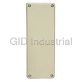
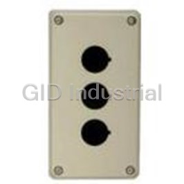
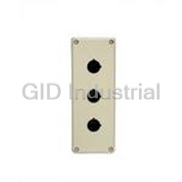
Enclosure Undrilled Non UL
FB2T-000Z
Part Number
FB2T-000Z
Price
Request Quote
Manufacturer
IDEC CORPORATION
Lead Time
Request Quote
Category
Fasteners, Hardware and Fluid Transfer » Boxes, Enclosures and Racks
Specifications
Manufacturer
IDEC Corporation
Manufacturers Part #
FB2T-000Z
Sub-Category
Boxes, Enclosures and Racks
Factory Pack Quantity
1
Datasheet

Extracted Text
FB Series
Plastic Control Boxes
(06/07/04)
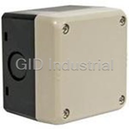
Lightweight Plastic Boxes with IP65 Protection
Lightweight Plastic Boxes with IP65 Protection
A wide variety of ş22mm control units can be installed.
Cover: Light Beige
Dimensions: 76/140/200H × 76W × 59.5D mm
Mounting Holes: 0 to 5 for mounting control units
HW Series
TW Series
XW Series
(Emergency Stop
Switch)
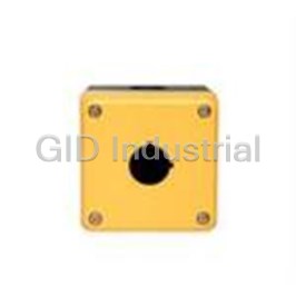
For Emergency Stop Switch
Cover: Yellow
Dimensions: 76H × 76W × 59.5D mm
Mounting Holes: 1 for mounting a control unit
Blank types Accessories
Blank enclosures, without mounting holes, are A wide variety of accessories can be installed to suit individual applications.
conducive to custom designed layouts, and also
allow the user to install control units of other
Nameplates Switch Guard Padlock Cover
sizes.
Yellow enclosure with switch guards HW9Z-KG3 and HW9Z-KG4 are SEMI S2 compliant.
For details, see the SEMI EMO Switch Guards catalog (EP1125).
(06/07/04)
2
A Wide Variety of Control Units Can Be Installed.
A Wide Variety of Applications
Contact Cover Box Junction Box
Control units become IP65 when covered with the contact Control boxes without mounting holes can also be used as junction
cover box (Type No. FB1WR-111Z. See pages 6 and 7 for boxes to enclose terminal blocks.
details).
Contact Cover Box
Applicable terminal blocks:
BN10W, BN15MW, BN15LW, BN30W, BA111T, BA211T, BA311T
Control Unit
Mounting Panel
A wide variety of mounting styles to suit your applications
• • • • Front Panel Mounting • • • • Hook Mounting
The control boxes can be The control boxes can
mounted to the front of the be hung on a hook.
panel.
For details, see page 5.
• • • • Rear Panel Mounting • • • • Frame Mounting
The control boxes can be The control boxes can be
mounted from behind the mounted on the middle,
panel. right, or left side of an
aluminum frame by using
For details, see page 5.
two FB9Z-PK1 mounting
brackets on the top and
bottom of the box.
For details, see page 7.
(06/07/04)
3
2-ş4.6
FB Series Plastic Control Boxes
IP65 lightweight plastic enclosures for installing control units.
• ş22mm control units can be installed.
• Blank front control boxes, without mounting holes, are also avail-
able.
• Blank front control boxes can also be used as junction boxes to
mount terminal blocks.
• Yellow cover version for emergency stop switches is also available.
• Front panel mounting, rear panel mounting, hook mounting, and
frame mounting options are available.
• UL/c-UL listing - pending
Types
• •
• • Box
No. of
Mounting Hole
Box Size Mounting Cover Color Type No.
Description
Holes
0 Without mounting hole Light beige FB1T-000Z
76mm 1 ş22mm Yellow FB1W-111Y
1 ş22mm FB1W-111Z
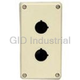
0 Without mounting hole FB2T-000Z
ş22mm, mounting
2 FB2W-211Z
140mm centers 50mm
76
ş21.3 Knockout
ş22mm, mounting
3 FB2W-312Z
centers 30mm
Light beige
0 Without mounting hole FB3T-000Z
Cover Mounting Screws
ş22mm, mounting
3 FB3W-311Z (Stainless Steel)
centers 50mm
200mm
ş22mm, mounting
4 FB3W-413Z
centers 36mm
Control Unit Mounting Holes
ş22mm, mounting
5 FB3W-512Z
centers 30mm
• • • • Specifications (Note 1)
Ambient temperature: –25 to +60°C (no freezing)
Standard
Relative humidity: 45 to 85%RH (no condensation)
Operating
Storage temperature: –40 to +80°C (no freezing)
Conditions
Degree of pollution: 3
IP65 (when IP65 control units are installed)
Degree of
NEMA Type 4X Indoor Use Only
Protection
(when Type 4X control units are installed)
Electric Shock
Class II (when class II control units are installed)
59.5
Protection
Cover/base: Polycarbonate ş21.3 Knockout
Material
Cover mounting screws: Stainless steel
Applicable Control IDEC’s HW/TW/XW series control units and
Dimensions
Units accessories (Note 2) (Note 3)
76mm type: 125g (FB1W-111Z)
• •
• • 76mm Type (FB1)
Weight (approx.) 140mm type: 184g (FB2W-211Z)
4-M4 Tapping Holes for Rear Mounting
200mm type: 243g (FB3W-311Z) (Depth: 10 mm)
ş66 (Marking Plate Area)
Cover
2-Front Mounting Holes
Note 1: The above speciŢcations are for control boxes. For control units, refer to the
Mounting Screws
Cover
ş14 Knockout
speciŢcations of each control unit.
Note 2: Choose control units and accessories which match the mounting hole cen-
ters, effective depth behind the cover, and the thickness of the cover where control
units are installed (3 mm). Note that control boxes with 30mm or 36mm mounting
hole centers may limit the knob orientation of selector switches, because the con-
tact blocks can be mounted in one direction only on these mounting centers.
Note 3: An XW series emergency stop switch of screw terminal type can be
installed on a control box with one mounting hole or mounting holes of 50mm
mounting centers, by connecting one clamping terminal to one terminal pole.
Base 15.5
• • • • Contact Cover Box
c 76
59.5 62
No. of
Mounting Hole
Size Mounting Cover Color Type No.
2-ş21.3 Contact Cover (FB1WR-111Z)
Description
Holes
Knockout
ş22mm hole in
76mm 1 Light beige FB1WR-111Z
the base
• Cover does not have a control unit mounting hole.
• For operating instructions, see page 6 and 7.
Base
• •
• • Accessories
Description Type No. Ordering Type No. Package Quantity
Mounting Bracket FB9Z-PK1 FB9Z-PK1 1
∗ Dimensions are the same as standard type.
DIN Rail Adapter FB9Z-PK3 FB9Z-PK3PN02 2
All dimensions in mm.
• For the dimensions and operating instructions, see pages 7 and 8.
• Connectors and nuts are supplied by users.
(06/07/04)
4
ş22.3
76, 140, or 200
18
21
21
41
4-R2.2
FB Series Plastic Control Boxes
• • • • 140/200mm Type (FB2/FB3)
Nameplate: NWA-∗, NWAQ-∗, NWAS-0,
NWAL-0, NWAQL-0, NWAV-∗
4-M4 Tapping Screw Holes for
Rear Mounting (Depth: 10mm) Anti-rotation ring: OGL-31
TW Series
2-Front Mounting Holes
Metal protector: OLW-C
Cover Mounting Screws Cover
Control Units
2-ş14 Knockout
Pushbutton clear boot: OC-31, OC-32
Button cover: OCW-10∗, OCW-11∗
Padlock cover: HW9Z-KL1, HS9Z-PC22
Note: ConŢrm the speciŢcations of control box, control units, and accessories
before choosing accessories, referring to separate catalogs.
Applicable DIN Rail
Description Material Type No.
Aluminum BAA1000
DIN Rail
Steel BAP1000
Mounting Clip Steel BNL6
Note: Use DIN rail adapters FB9Z-PK3 when installing a DIN rail in the control box.
See pages 7 and 8.
Base 31
59.5
76 62
Applicable Terminal Block / Transformer
Series / Type No.
FB2 FB3
2-ş21.3 Knockout
L 140 200 BN-W Series: BN10W, BN15MW, BN15LW, BN30W
Terminal Block
A 84 144
BA Series: BA111T, BA211T, BA311T
B 104 164
Separate Mounting
∗∗
TWR5
C 106 166
Transformer
All dimensions in mm. Note: Install the terminal blocks and separate mounting transformers on a DIN rail
using two DIN rail adapters (FB9Z-PK3). Choose the types and quantity of terminal
blocks, transformers, mounting clips, and control boxes carefully taking the speciŢ-
Control Unit Mounting Hole Centers
cations into consideration. The separate mounting transformer can be installed on a
FB2 FB3
DIN rail adapter directly.
Type FB1
2 mounting 3 mounting 3 mounting 4 mounting 5 mounting
holes holes holes holes holes
Instructions
Installation
Panel Mounting
1. Installing the FB series from the front
• Using two M4 screws, install Mounting Screws
Mounting Hole Dimensions (M4)
5.0 mm
the base onto the panel.
(Base
FB2 FB3 FB2/FB3
Recommended tightening
Thickness)
50mm 36/50mm torque: 1.4 to 2.0 N·m
Type FB1
mounting mounting 30mm mounting centers
∗ Determine the screw length in
centers centers
consideration of the base and panel
3.2
thickness.
∗ Mounting screws are not supplied
Panel
Box Base
with the FB series. Use M4 mount-
Shape
ing screws.
13
13
2. Installing the FB series from the rear
• Insert four M4 tapped screws into holes for tapping screws on the
Note: For contact cover boxes, see page 4.
back of the base (depth: 8 to 10 mm, tapping screw hole diameter:
Internal Dimensions
ş3.7 mm), and fasten the screws to a tightening torque of 1.3±0.1
N·m (Nitto Seiko M4-P-TITE).
FB1 FB2 FB3
∗ Mounting screws are not supplied with the FB series. Use M4 tapping
D 45 92 150 screws (recommended screws: Nikko Seiko M4-P-TITE).
∗ The value of the recommended tightening torque has been conŢrmed
Note: Choose a control box in consider-
with a M4 tapping screw (Nitto Seiko M4-P-TITE). When using other
ation of control unit’s depth behind
45
the panel and the mounting cen- screws, check that the tapping screw hole is not damaged and the screw
Control Unit
ters of the adjacent control units. can be securely tightened.
Mounting Area
Thickness
3. Installation using mounting bracket FB9Z-PK1
• Refer to installation instructions on page 7.
All dimensions in mm.
Installing and Removing the Control Unit
• Refer to installation instructions for each control unit.
Applicable Accessories
Series Description
Installing the Safety Lever Lock for HW Series Control
Nameplate: HWAM, HWAQ, HWAS, HWAV-∗
Units (HW9Z-LS, yellow)
Marking plate for nameplate: HWNP-∗
• When installing the HW series control units in the direction shown
Anti-rotation ring: HW9Z-RL
below, install the safety lever lock with the lever in the unlocked
HW Series
EMO switch guard: HW9Z-KG3, HW9Z-KG4 position, lock the lever, and push in the safety lever lock.
Control Units
Switch guard: HW9Z-K1, HW9Z-K11
3
Pushbutton clear boot: OC-31, OC-32
Padlock cover: HW9Z-KL1
1
Nameplate: HWAV-∗
XW Series
Emergency EMO switch guard: HW9Z-KG3, HW9Z-KG4
2
Safety Lever Lock
Stop Switches
Anti-rotation ring: HW9Z-RL
(06/07/04)
5
ş22.3
ş22.3
55
Appearance
2
3 D
13
L
50
18
3.2
30 30
50 50
36 36 36
3.2
A
B
30 30 30 30
C
FB Series Plastic Control Boxes
Instructions
Installing the Cable Gland 2. When using plastic cable gland, metal cable gland and multi-core
cable
• Break a desired knockout to mount a cable gland
Gland Port Size Plastic Cable Gland Metal Cable Gland
using a hammer and a screwdriver, and install the
5311 1220 [Skintop-ST-M]
cable gland.
M20 Applicable gasket: GPM20 ALS-∗∗ EC20 (Nihon Flex)
∗ When breaking the knockout to make a cable gland hole,
(LAPP, Germany)
be careful not to damage the internal contact block.
5380 6030 [Skintop-ST-PF]
∗ Note that cracks or burrs on the cable gland hole will
G1/2 Applicable gasket: GP 050 ALS16-∗∗ (Nihon Flex)
degrade the waterproof characteristics.
(LAPP, Germany)
Installing the Cover and Base
5301 5030 [Skintop-ST]
∗∗
PG13.5 Applicable gasket: GP13.5 ABS- PG13.5 (Nihon Flex)
• Attach the cover to the base so that the TOP mark on the cover
(LAPP, Germany)
and base are in the same direction.
• Use cover mounting screws
3. Locking nut for installing the cable gland
to attach the cover to the
TOP
Gland Port Size Locking Nut Type No. (made of plastic)
base. (Recommended tight- TOP
M20 HW9Z-NM20 (IDEC)
ening torque: 1.3±0.1 N·m)
TOP
G1/2 HW9Z-G (IDEC)
∗ Make sure that the cover and
Marking
the base are attached in the
PG13.5 HW9Z-PG135 (IDEC)
correct direction. Otherwise,
the FB series may be dam-
• Tighten cable glands to a torque of 3.0±0.3 N·m.
(Cover) (Base)
aged.
∗ InsufŢcient tightening of the cable gland may degrade the waterproof
characteristics.
∗ Electric shock protection Class II is maintained only when a plastic cable
Applicable Crimping Terminal
gland is used. When using metallic cable glands, install a proper ground-
ing provision or use only one cable gland.
HW/TW Series
• Determine the cable gland for a multi-core cable according to the
Non-insulated Terminal Insulated Terminal
outside diameter of the cable sheath.
Applicable Crimping Terminal
• When wiring from the back of FB series, use the ş14 knockout on
Insulating Tube
ş3.6 min. ş3.6 min. the back of the control box. A cable gland cannot be installed to
Wire
the ş14 knockout.
W
W
4.0 max. 6.0 min.
20.2 max.
4.0 max. 6.0 min. Notes
20.2 max
A A
Applicable Wire Size
W dimensions
• Determine the wire size in consideration of the applicable wire for
B B
Direction of A: 8.0 maximum
control units and the applicable diameter of cables.
Direction of B: 6.6 maximum
Wiring
• Avoid foreign objects such as dust, liquid, and oil from entering the
B
B
switch while connecting a conduit or wiring.
A A
• Do not twist or pull the cable of ţexible conduit with excessive
force. Otherwise, the wire, FB series, and control units may be
damaged.
XW Series (Screw Terminal Type��
��
• Because the FB series is not provided with a PG terminal, bond-
Non-insulated Terminal Insulated Terminal
ing circuits cannot be interconnected.
Applicable Crimping Terminal
Insulating Tube
Installation of control units on 30mm centers
ş3.2 min. ş3.2 min.
Wire
• When mounting HW/TW series control units
30
6.0 max.
6.0 max. on 30mm mounting centers (close mounting),
4.7 min.
make sure to use a barrier (optional: HW-
3.0 max. (Note) 4.7 to 5.9 3.0 max. 4.7 to 5.9
VG1) to secure the insulation properties of the
14.9 max. 18.3 max. 14.9 max.
terminal. The barriers (HW-VG1) can be eas-
∗ When a spade terminal is used, the dimension is 4.7 to 5.9 mm.
ily pressed into the side of the contact block.
∗ Be sure to install an insulating tube on the crimping terminal.
Operation Barrier
∗ When using crimping terminals for the XW series, use only one crimping
(optional, HW-VG1)
• Avoid any contact with oil or coolants.
terminal for each terminal.
Otherwise, the control box may be damaged.
∗ Make sure that the wiring does not contact the FB series.
• Use the FB series for INDOOR applications only.
Applicable Cable Gland
Contact Cover Box
• Use cable glands with waterproof M20. G1/2
SpeciŢcations, applicable units, and wiring
PG13.5
characteristics (IP65, TYPE 4X)
which can be mounted on a panel • Same as the standard control boxes.
thickness of 3 mm or more.
30 mm
Installing XW series control units to the FB1WR-111Z
max.
∗ Locking nuts are not attached.
contact cover
10 mm max.
1. When using ţexible conduit and
• Remove the contact block and the locking ring from the operator
All dimensions in mm.
metal cable gland.
and check that the rubber gasket is in place. Insert the operator
from panel front into the panel hole. Attach the rubber gasket and
• Applicable Flexible Conduit Example: Type VF-03 (Nihon Flex)
the base to the operator unit (place the rubber gasket between the
Gland Port Size Plastic Cable Gland Metal Cable Gland
panel and the base) and tighten the locking ring using locking ring
wrench MW9Z-T1. Recommended tightening torque: 2.0 N·m
M20 — RLC-103EC20 (Nihon Flex)
• Attach the contact block to the operator. After wiring, attach the
G1/2 — RLC-103 (Nihon Flex)
cover to the base using four cover mounting screws. Recom-
PG13.5 — RBC-103PG13.5 (Nihon Flex)
mended tightening torque:1.3±0.1 N·m
• Use a nameplate if necessary.
(06/07/04)
6
R3.3
FB Series Plastic Control Boxes
Instructions
• Determine the panel thickness by excluding the thickness of the Dimensions
base (2.0 mm) and accessories (if used) from the maximum panel
Frequently asked questions
How does Electronics Finder differ from its competitors?

Is there a warranty for the FB2T-000Z?
Which carrier will Electronics Finder use to ship my parts?
Can I buy parts from Electronics Finder if I am outside the USA?
Which payment methods does Electronics Finder accept?
Why buy from GID?

Quality
We are industry veterans who take pride in our work

Protection
Avoid the dangers of risky trading in the gray market

Access
Our network of suppliers is ready and at your disposal

Savings
Maintain legacy systems to prevent costly downtime

Speed
Time is of the essence, and we are respectful of yours
Related Products
Yellow Polycarbonate Wall Mount Enclosures FB1W-111Y
Beige Polycarbonate Wall Mount Enclosure FB1WR-111Z
Beige Polycarbonate Wall Mount Enclosures FB2W-211Z
Beige Polycarbonate Wall Mount Enclosures FB2W-312Z
Beige Polycarbonate Wall Mount Enclosures FB3W-311Z
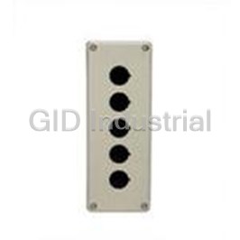
Enclosure 5 Hole, Beige FB3W-512Z
Request a Quote

The quote request has been received
Close

Facing challenges or have inquiries? Feel free to contact us!
Call Us +1-469-283-2440
What they say about us
FANTASTIC RESOURCE
One of our top priorities is maintaining our business with precision, and we are constantly looking for affiliates that can help us achieve our goal. With the aid of GID Industrial, our obsolete product management has never been more efficient. They have been a great resource to our company, and have quickly become a go-to supplier on our list!
Bucher Emhart Glass
EXCELLENT SERVICE
With our strict fundamentals and high expectations, we were surprised when we came across GID Industrial and their competitive pricing. When we approached them with our issue, they were incredibly confident in being able to provide us with a seamless solution at the best price for us. GID Industrial quickly understood our needs and provided us with excellent service, as well as fully tested product to ensure what we received would be the right fit for our company.
Fuji
HARD TO FIND A BETTER PROVIDER
Our company provides services to aid in the manufacture of technological products, such as semiconductors and flat panel displays, and often searching for distributors of obsolete product we require can waste time and money. Finding GID Industrial proved to be a great asset to our company, with cost effective solutions and superior knowledge on all of their materials, it’d be hard to find a better provider of obsolete or hard to find products.
Applied Materials
CONSISTENTLY DELIVERS QUALITY SOLUTIONS
Over the years, the equipment used in our company becomes discontinued, but they’re still of great use to us and our customers. Once these products are no longer available through the manufacturer, finding a reliable, quick supplier is a necessity, and luckily for us, GID Industrial has provided the most trustworthy, quality solutions to our obsolete component needs.
Nidec Vamco
TERRIFIC RESOURCE
This company has been a terrific help to us (I work for Trican Well Service) in sourcing the Micron Ram Memory we needed for our Siemens computers. Great service! And great pricing! I know when the product is shipping and when it will arrive, all the way through the ordering process.
Trican Well Service
GO TO SOURCE
When I can't find an obsolete part, I first call GID and they'll come up with my parts every time. Great customer service and follow up as well. Scott emails me from time to time to touch base and see if we're having trouble finding something.....which is often with our 25 yr old equipment.
ConAgra Foods