

 Manufacturers
IDEC CORPORATION FC2A-KP1C
Description
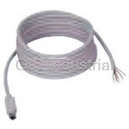
Cable Assembly Communication 2.4m RS232C
FC2A-KP1C
Part Number
FC2A-KP1C
Price
Request Quote
Manufacturer
IDEC CORPORATION
Lead Time
Request Quote
Category
Wire and Cables » Cable Assembly Other
Specifications
Manufacturer
IDEC Corporation
Manufacturers Part #
FC2A-KP1C
Lead Time
4 Week Lead Time
Sub-Category
Cable Assemblies
Factory Pack Quantity
1
Datasheet

Extracted Text
MicroSmart EXPANDING YOUR CONTROL FC4A Series Micro PLC Table of Contents MicroSmart FC4A Series Micro PLC 2-3 Multipule Standard Features 4-5 Add And Combine Modules 6 Customize MicroSmart To Meet Your Needs 7 CPU Modules 8 Expansion Modules And Options 9-11 Easy Operation Using The HMI Module 12 Communication Capabilities 13 Compatible Programming Software 14 Product List 23 SpeciŢcations 16-22 Programming Instruction Commands 23 Dimensions 25-26 Accessories 27 2 IDEC Corporation, a pioneer in the micro-PLC Ţeld, is proud to offer the MicroSmart series of programmable logic controllers, the latest in the Micro family of PLCs. These ţexible, adaptable PLCs are as compact as they are powerful, so you can create the system you need without increasing your space requirements or your budget. The CPU That’s Right For You MicroSmart CPUs are available in two types of modules, All-in-One and Slim. The All-in-One type has models with 10, 16, or 24 I/O points; the Slim type is available in four different 20 I/O modules and two 40 I/O modules. Each CPU module is only 90mm in height and 70mm deep, but it has built-in inputs and outputs as well as standard features like high-speed counters, a RS-232C port and an analog potentiometer. Choose the CPU that’s right for you and see what else MicroSmart has to offer. Expand Your Control The Slim type and the 24 I/O All-in-One type CPUs can expand into the ideal system using the optional expansion modules. Need more inputs? More outputs? Some of both? There are 18 available expansion modules, including four analog I/O modules. Depending on your CPU, you can create a system with as many as 264 I/O points (40 I/O Slim type CPU with seven expansion modules). Customize Your System Once you have all the control you need, select the features you want. Store and transfer programs on the memory cartridge or install a real-time clock and calendar cartridge. Add another communications port or an HMI module — it’s all possible with MicroSmart. It’s even UL-1604 listed, Class 1–Div. 2 for hazardous locations. Create the perfect solution for all of your applications, exactly the way you want it. 3 Multiple Standard Features Pulse Output/Trapezoidal Control Independent dual-axis control is available with two pulse outputs. Locational values can be easily deŢned for precise positional (trapezoidal) control. * Pulse output instruction * PWM instruction (Pulse Width Modulation control) Pulse Output Function SpeciŢcations Number of output points 2 Maximum output frequency 20 kHz Only one point of trapezoidal control is available. * Setting the desired values enables you to precisely manage the trapezoidal control Hz Trapezoidal control Operation mode (S1) 1 (RAMP) Steady speed Steady pulse frequency (S1 + 1) 50 5000 Initial pulse frequency (S1 + 2) 10 Freguency change rate (S1 + 3) 2 Preset value (S1 + 6, 7) 10,000 Initial speed RAMP S1 D1 ms 0 Acceleration period Deceleration period PID Control To automatically maintain a target water temperature (PID control), use the auto tuning function to perform sampling. Based on the determined PID parameters, PID control is executed automatically. (Slim type CPU units only.) Water temperature High alarm value 33°C Set point 30°C Low alarm Set point 30 value 27°C AT set point 25 AT set point 25°C High alarm value 35 Low alarm value 27 Time PID S1 S2 S3 S4 D1 Auto tuning PID control 4 High-speed Counters The MicroSmart has four built-in high speed counters. One high speed counter (all-in-one type) or two high speed counters (slim type) can be used as either two-phase or single-phase high speed counters at a maximum of 20kHz. The other three (all-in-one type) or two (slim type) have a maximum frequency of 5kHz. High speed counters are used for simple positioning and motor control. Type Single-phase Two-phase Maximum HSC1 and 4: 20 kHz HSC1: 20 kHz Input HSC2 and 3: 5 kHz HSC4: 20 kHz (SlimType CPU) Frequency Counting Range 16 bits (0 to 65,535) 16 bits (0 to 65,535) The rotary encoder can connect directly to the paper feeder. Operation Mode Adding counter Rotary encoder The high-speed counter receives and reads output pulses from (phases A, B, Z) the rotary encoder. Gate Input Enable/disable counting Enable/disable counting Current Current value is reset to Current value is reset to zero when the current a given value when Value value reaches the pre- overflow or underflow Reset set value. has occurred. Analog Potentiometer The analog potentiometer built into the CPU module enables settings to be adjusted without special tools. All-in-One Type Slim Type Two built-in 24-I/O type Standard on all models One built-in 10/16-I/O types After installation the analog potentiometer in the CPU module allows you to easily change values such as timer preset values or the volume of water. Built-in Analog Voltage Input Ready for connecting 0 to 10V DC from an external device directly to the built-in analog voltage input connector (Slim type CPU modules only). External Device Slim Type Speed Control 5 Add And Combine Modules All-In-One Type I/O points Maximum I/O 88 FC4A-N16B3 Attach Max. 4 Expansion Modules 16 • Max. I/O 88 points • FC4A-M24BR2 FC4A-N16B3 Only FC4A-C24R2 CPU • 16 Module is expandable 24 FC4A-R161 FC4A-N08B1 50 8 Note: The maximum number of relay outputs that FC4A-M24BR2 16 FC4A-N08B1 FC4A-R161 can be turned on simultaneously is 33 points including relay outputs on the CPU module. 8 16 FC4A-N08B1 FC4A-R161 24 8 16 FC4A-N08B1 FC4A-N08B1 24 on CPU 8 8 FC4A-C24R2 FC4A-C24R2 FC4A-C24R2 FC4A-C24R2 FC4A-C24R2 16 on CPU FC4A-C16R2 10 on CPU 24 on CPU 24 on CPU 24 on CPU 24 on CPU FC4A-C10R2 6 Inputs 9 Inputs 14 Inputs 30 Inputs 46 Inputs 38 Inputs 46 Inputs 4 Outputs 7 Outputs 10 Outputs 18 Outputs 10 Outputs 34 Outputs 42 Outputs 10 Total I/O 16 Total I/O 24 Total I/O 48 Total I/O 56 Total I/O 72 Total I/O 88 Total I/O Combination Examples Slim Type Maximum I/O 264 I/O points FC4A-N32B3 250 FC4A-T32K3 32 Attach Max. 7 Expansion Modules 32 • FC4A-T32S3 FC4A-T32K3 32 Max. I/O 148 points (D20K3, D20S3) • 200 FC4A-M24BR2 244 points (D20RK1,D20RS1) 32 FC4A-N32B3 24 264 points (D40K3, D40S3) FC4A-T32K3 FC4A-T32K3 32 32 32 FC4A-T32S3 150 FC4A-M24BR2 FC4A-T32K3 FC4A-T32K3 32 Note: The maximum number of relay outputs that 24 can be turned on simultaneously is 54 points 32 32 FC4A-N32B3 FC4A-T16S3 including relay outputs on the CPU module. 16 FC4A-N16B3 FC4A-N32B3 32 FC4A-T16S3 FC4A-T32S3 16 16 100 32 FC4A-T32S3 32 FC4A-N32B3 FC4A-T32S3 FC4A-N32B3 32 32 32 FC4A-N32B3 32 32 FC4A-N32B3 FC4A-T32S3 FC4A-N32B3 32 50 32 32 FC4A-N32B3 FC4A-N32B3 40 on CPU 32 20 on CPU FC4A-D40S3 32 FC4A-D40K3 FC4A-D40S3 FC4A-D40K3 FC4A-D20K3 FC4A-D40S3 FC4A-D20RS1 FC4A-D20RK1 FC4A-D20S3 40 on CPU 40 on CPU 40 on CPU FC4A-D20RK1 20 on CPU 20 on CPU FC4A-D20RS1 12 Inputs 24 Inputs 24 Inputs 92 Inputs 120 Inputs 108 Inputs 152 Inputs 8 Outputs 16 Outputs 96 Outputs 64 Outputs 88 Outputs 136 Outputs 112 Outputs 20 Total I/O 40 Total I/O 120 Total I/O 156 Total I/O 208 Total I/O 244 Total I/O 264 Total I/O Combination Examples 6 Customize MicroSmart To Meet Your Needs All-in-One Type FC4A-C10R2, FC4A-C16R2, FC4A-C24R2 Communication Adapters (FC4A-C10R2 not applicable) RS232C Communication Adapter (FC4A-PC1) (Mini-DIN Type) Expansion I/O Module (FC4A-C10R2 and FC4A-C16R2 not expandable) RS485 Communication Adapter (FC4A-PC2) (Mini-DIN Type) OR RS485 Communication Adapter (FC4A-PC3) HMI Module Memory Cartridge (Screw Terminal Type) (FC4A-PH1) (FC4A-PM32) or (FC4A-PM64) Clock Cartridge (FC4A-PT1) Slim Type FC4A-D20K3, FC4A-D20S3, FC4A-D20RK1 FC4A-D20RS1, FC4A-D40K3, FC4A-D40S3 HMI Module (FC4A-PH1) HMI Base Module (FC4A-HPH1) Communication Adapters Communication Modules RS232C Communication Adapter Expansion I/O Module (FC4A-PC1) RS232C Communication Module (Mini-DIN Type) (FC4A-HPC1) (Mini-DIN Type) Memory Cartridge Two kinds of cartridges can be used at (FC4A-PM32) or ( ) the same time with slim type CPUs only. (FC4A-PM64) RS485 Communication Adapter RS485 Communication Module (FC4A-PC2) (FC4A-HPC2) (Mini-DIN Type) (Mini-DIN Type) Clock Cartridge (FC4A-PT1) RS485 Communication Adapter RS485 Communication Module (FC4A-PC3) (FC4A-HPC3) (Screw Terminal Type) (Screw Terminal Type) 7 CPU Modules CPU Modules FC4A-C10R2 FC4A-C16R2 FC4A-C24R2 6 input points 9 input points 14 input points 4 output points 7 output points 10 output points Relay output Relay output Relay output 100 to 240V AC 100 to 240V AC 100 to 240V AC 4.8KB memory 15KB memory 27KB memory 88 max I/O expandability I/O modules not applicable to these two models FC4A-D20K3 FC4A-D20RK1 FC4A-D40K3 12 input points 24 input points 12 input points 16 output points 8 output points 8 output points 0.3A transistor sink output 0.3A transistor sink output 0.3A transistor sink output 24V DC 24V DC 24V DC 27KB memory 31.2KB memory 31.2KB memory 148 max I/O expandability 244 max I/O expandability 264 max I/O expandability 240V AC-2A/30V DC-2A relay output *Transistor output 2 points and relay output 6 points FC4A-D20S3 FC4A-D20RS1 FC4A-D40S3 12 input points 12 input points 24 input points 8 output points 8 output points 16 output points 0.3A transistor source output 0.3A transistor source output 0.3A transistor source output 24V DC 24V DC 24V DC 27KB memory 31.2KB memory 31.2KB memory 148 max I/O expandability 244 max I/O expandability 264 max I/O expandability 240V AC-2A/30V DC-2A relay output *Transistor output 2 points and relay output 6 points 8 Expansion Modules And Options DC Input Modules - 4 Types 16-point DC Input 32-point DC Input 8-point DC Input Module 16-point DC Input Module Module Module FC4A-N08B1 FC4A-N16B1 FC4A-N16B3 8 input points 16 input points FC4A-N32B3 16 input points 32 input points 24V DC sink/source input 24V DC sink/source input 24V DC sink/source input 24V DC sink/source input Removable screw terminal Removable screw terminal MIL connector MIL connector Output Modules - 8 Types 8-point Relay 8-point Transistor 16-point Relay 8-point Transistor Output Module Sink Output Module Output Module Source Output Module FC4A-T08K1 FC4A-R081 FC4A-R161 FC4A-T08S1 8 output points 16 output points 8 output points 8 output points 0.3A transistor sink output Relay output (1NO contact) Relay output (1NO contact) 0.3A transistor source output Removable screw terminal Removable screw terminal Removable screw terminal Removable screw terminal 16-point Transistor 16-point Transistor 32-point Transistor 32-point Transistor Source Output Module Sink Output Module Source Output Module Sink Output Module FC4A-T32S3 FC4A-T16K3 FC4A-T16S3 FC4A-T32K3 16 output points 16 output points 32 output points 32 output points 0.1A transistor source output 0.1A transistor sink output 0.1A transistor sink output 0.1A transistor source output MIL connector MIL connector MIL connector MIL connector 9 Expansion Modules And Options Cont. Combination I/O Modules - 2 Types 4 Input/4 Output 16 Input/8 Output Combination Module Combination Module FC4A-M08BR1 FC4A-M24BR2 4 input points/4 output points 16 input points/8 output points 24V DC sink/source input 24V DC sink/source input 240V AC-2A/30V DC-2A relay output 240V AC-2A/30V DC-2A relay output Wire-clamp terminal Removable screw terminal Analog Modules - 4 Types 2 Input/1 Output 1 Output 2 Input 2 Input/1 Output Analog Module Analog Module Analog Module Analog Module FC4A-L03A1 FC4A-K1A1 FC4A-J2A1 FC4A-L03AP1 2 analog input (thermocouple/RTD) 2 analog input (voltage/current) 1 analog output (voltage/current) 2 analog input (voltage/current) Removable screw terminal Removable screw terminal 1 analog output (voltage/current) 1 analog output (voltage/current) Removable screw terminal Removable screw terminal Expansion Module Examples Module Type No. Input Output Module Type No. Input Output CPU FC4A-C24R2 14 10 CPU FC4A-C24R2 14 10 DC Input FC4A-N16B1 16 0 DC Input FC4A-N08B1 8 0 DC Input FC4A-N16B1 16 0 DC Input/Relay Output FC4A-M08BR1 4 4 Relay Output FC4A-R161 0 16 Relay Output FC4A-R081 0 8 Relay Output FC4A-R161 0 16 Transistor Sink Output FC4A-T08K1 0 8 Total 46 42 Total 26 30 10 1)(Example 2)(Example Option Modules HMI Base Module HMI Module Memory Cartridge Clock Cartridge (FC4A-HPH1) (FC4A-PH1) (FC4A-PM32) (FC4A-PT1) (FC4A-PM64) Communication Adapters (FC4A-PC1) (FC4A-PC2) (FC4A-PC3) Slim Type Communication Modules (FC4A-HPC1) (FC4A-HPC2) (FC4A-HPC3) Communication Type CPU Module HMI Module Memory Cartridge Clock Cartridge Adapter 24 YES YES 16 YES YES Select one cartridge - 10 40 YES YES YES YES* HMI Base Module 20 *Communication module or combination of communication adapter mounted on HMI base module 11 Slim Type All-in-one Type Easy Operation Using The HMI Module vs. Easy mounting Ease of operation and compact size No need for special tools Recover a system failure Set the time and calendar immediately by reading the with optional clock cartridge error codes. The HMI Module allows you to access the following menus Timer Menu Counter Menu Data Register Menu Input Menu Clock Cartridge Output Menu Internal Relay Menu Shift Register Menu Monitor and change the Error Menu Run/Stop Menu status and setup of your Calendar Menu CPU while the system is Clock Menu in operation 12 Communication Capabilities Expand The Network Of Control Systems Serial Communication Functions Data Link System (The Data Link System is not available for the All-in-One 10 I/O module) OpenNet Controller (Master) and MicroSmart (Slave) (Master) (Slave 1) (Slave 2) (Slave 31) T el Establishes a data link system using the OpenNet Controller as a master and a maximum of 31 MicroSmart CPU modules as slaves. Distributed control on an RS485 network is made possible without the need for communication programs. (RS485 communication adapter is required to set up a data link system.) MicroSmart (Master) and MicroSmart (Slave) (Master) (Slave 1) (Slave 2) (Slave 3) (Slave 31) T el Distributed MicroSmart CPU modules at each processing stage can be controlled as one integrated system without a host. One MicroSmart as a master interface with up to 31 MicroSmart modules on an RS485 network without the need for communication programs. (RS485 communication adapter is required to set up a data link system.) Computer Link System (1:N) MicroSmart (Master) and MicroSmart (Slave) (1st Unit) (2nd Unit) (32nd Unit) T el reretv Up to 32 MicroSmart modules can be connected to a PC. The values of timers and counters, data of data registers, and I/O status can be monitored on the PC. Also, user programs can be downloaded to the MicroSmart to establish a total supervisory system. (RS485 communication adapter is required to set up a 1:N computer link system.) Connecting to Operator Interface el The MicroSmart can be connected to IDEC's HG series Operator Interface. The HG series can exchange dataTel with each device in the MicroSmart. Also, the HG can graphically display the values of timers and counters, data of data register, and I/O status. 13 required.)isadapter comm(RS485unication cabshieldedwisted-pair (FC4A-KC2C) cabconnectionPLC FC2A-MD1(HD9Z-C52) ConCabRS232Cle cabshieldedpair RS232C/RS485 wisted-long200m cabshieldedpair wisted-long200m cabshieldedpair wisted-long200m Windows Compatible Programming Software ® for Windows ® WindLDR is a software package to program the MicroSmart and all of IDEC’s ® other programmable logic controllers. Upgraded WindLDR version 4.0 or higher supports new functions incorporated in the MicroSmart, such as partial download (16 and 24 I/O type units only) and comment download functions. ® Note: Please use WindLDR 4.0 or higher for programming MicroSmart. System Requirements OS: Windows 2000, Windows 98, Windows 95, Windows NT4.0 (Service Pack 3 or higher) CPU: Pentium 75MHz or higher Memory: 24MB of available RAM on Windows 95 and Windows 98, 32MB of available RAM on Windows NT HD: 20MB of available hard-disk space ® The WindLDR modem communication function cannot be used on Windows 95. 1. Improved Operation of the Ladder 2. Cache Function in Ladder to 3. Comment Download Function Program Editor Mnemonic Conversion ® When a user program is modiŢed, WindLDR 4.0 The MicroSmart can store comments attached to The right power rail can be Ţxed. When a program line exceeds the right power rail, a or higher converts only the modiŢed portion of the the user program. Since a user program can be connection line is automatically inserted. Also, program, saving conversion time when modiŢcation downloaded to the MicroSmart with comments the ladder program can be printed out with a and downloading are repeated during debugging. attached to operands and rungs, the recorded Ţxed power rail for clear viewing. comments can be restored from the MicroSmart without a ladder Ţle. This function is also available on the OpenNet Controller. 5. Cover Page 4. Modem Communication ® WindLDR can supervise operation and collect A cover page editor is provided to record the data from a remote PLC via modem and phone program name and creation date. The cover page line. Control possibilities can be expanded by stores information on each user program to help using the modem control function of the archive many user programs. MicroSmart or OpenNet Controller. 14 Product Selection List The Next Generation of PLC • Compact CPU modules available in All-in One or Slim types with 10, 16, 20, 24, or 40 I/O • DC Input, Relay Output, Transistor Output, Combination I/O and Analog I/O expansion modules • 24 I/O All-in-One CPU expandable to 88 I/O points; 20 I/O slim types expandable up to 148 or 244 I/O; 40 I/O slim type expand- able up to 264 I/O • Standard RS232 port, optional plug-in RS485/RS232 port • Optional memory cartridge or real-time clock and calendar cartridge • UL listed for hazardous locations CUS R Combination I/O Modules 15 Product Selection List Cont. / SpeciŢcations Miscellaneous Accressories Part No. Cable Accessories Part No. RS232C, Mini DIN FC4A-PC1 Programming Cable, CPU to PLC RS232 (3m) FC2A-KC4C Communication RS485, Mini DIN FC4A-PC2 User Communication Cable, RS232 (2.4m) FC2A-KP1C Adapter RS485, Screw terminal Type FC4A-PC3 Combo Prog./User Comm. Cable, port 1 only (3m) FC4A-KC4C Clock Cartridge FC4A-PT1 Modem Cable, PLC to Modem RS232 (3m) FC2A-KM1C Memory Cartridge (32KB) FC4A-PM32 O/I Communication Cable for HG Series RS232 (5m) FC4A-KC1CA O/I Communication Cable for HG2F, port 1 only (5m) FC4A-KC2CA Memory Cartridge (64KB) FC4A-PM64 RS232C/RS485 Converter FC2A-MD1 0.5m FC9Z-H050B20 1m FC9Z-H100B20 20 pt. Module BX1D-S20A MIL Connector Non-shielded Breakout Modules 2m FC9Z-H200B20 26 pt. Module BX1D-S26A 16pt. and 32pt. 20 wire for I/O Modules FC4A-PMC20P 3m FC9Z-H300B20 I/O Modules MIL Connector Socket 26 wire for CPU I/O FC4A-PMC26P 0.5m FC9Z-H050A20 20-wire 10 pt. Block FC4A-PMT10P 1m FC9Z-H100A20 Shielded 11 pt. Block FC4A-PMT11P 2m FC9Z-H200A20 I/O Terminal Blocks 13 pt. Block FC4A-PMT13P 3m FC9Z-H300A20 (package qty 2) Shielded w/Single FC4A-PMTK16P 1.52m FC9Z-H100C20A 16 pt. Block wire Connectors FC4A-PMTS16P 0.5m FC9Z-H050B26 FC4A-PMAC2P Analog Voltage Input Cable (1m/3.28 ft. long) 1m FC9Z-H100B26 Direct Mounting Strips FC4A-PSP1P Non-shielded 2m FC9Z-H200B26 BAA1000 3m FC9Z-H300B26 20pt. and 40pt. 35mm Aluminum DIN Rails (1.5m/3.28 ft. long) BNDN1000 0.5m CPU Modules FC9Z-H050A26 26-wire Mounting Clips BNL6 1m FC9Z-H100A26 Shielded 2m FC9Z-H200A26 3m FC9Z-H300A26 Shielded w/Single 1.52m FC9Z-H100C26A wire Connectors CPU General SpeciŢcations FC4A-D20K3 FC4A-D20RK1 FC4A-D40K3 Part No. FC4A-C16R2 FC4A-C24R2 FC4A-C10R2 FC4A-D20S3 FC4A-D20RS1 FC4A-D40S3 Type All-in-one Type CPU Module Slim Type CPU Module Rated Power Voltage 100 to 240V AC 24V DC Allowable Voltage Range 85 to 264V AC 20.4 to 26.4V DC (including ripple) Rated Power Frequency 50/60Hz (47 to 63Hz) – *2 *3 *3 Maximum Input Current 0.25A (85V AC) 0.30A (85V AC) 0.45A (85V AC) 0.56A (26.4V DC) 0.70A (26.4V DC) *1 *1 *2 *3 *3 30VA/264V AC 31VA/264V AC 40VA/264V AC 15W/26.4V DC 19W/26.4V DC Maximum Power Consumption 20VA/100V AC 22VA/100V AC 33VA/100V AC Allowable Momentary Power 20 msec (at the rated inputs and outputs) 10 msec (at 24V DC) Interruption Between power and terminals: 500V AC, 1 minute Between power and terminals: 1500V AC, 1 minute Dielectric Strength Between I/O and terminals: 1500V AC, 1 minute Between I/O and terminals: 1500V AC, 1 minute Insulation Resistance Between power and terminals: 10 MΩ minimum Between power and terminals: 10 MΩ minimum (500V DC megger) Between I/O and terminals: 10 MΩ minimum Between I/O and terminals: 10 MΩ minimum AC power terminals: 1.5 kV, 50 nsec to 1 µsec DC power terminals: 1.0 kV, 50 nsec to 1 µsec Noise Resistance I/O terminals (coupling clamp): 1.5 kV, 50 nsec to 1 µsec I/O terminals (coupling clamp): 1.5 kV, 50 nsec to 1 µsec Inrush Current 35A maximum 35A maximum 40A maximum 50A maximum (24V DC) Power Supply Wire UL1015 AWG22, UL1007 AWG18 Operating Temperature 0 to 55°C Storage Temperature –25 to +70°C Relative Humidity Level RH1, 30 to 95% (non-condensing) Operation: 0 to 2,000m (0 to 6,565 feet) Altitude Transport: 0 to 3,000m (0 to 9,840 feet) Pollution Degree 2 (IEC 60664) Corrosion Immunity Free from corrosive gases Degree of Protection IP20 Grounding Wire UL1007 AWG16 UL1015 AWG22, UL1007 AWG18 2 DIN rail mounted 10 to 57 Hz amplitude 0.075 mm, 57 to 150 Hz acceleration 9.8 m/sec (1G) 2 hours in each of 3 axes Vibration 2 Resistance Direct mounted 2 to 25 Hz amplitude 1.6 mm, 25 to 100 Hz acceleration 39.2 m/sec (4G) 90 minutes in each of 3 axes 2 Shock Resistance 147 m/sec (15G) ,11 msec duration, 3 shocks per axis, on three mutually perpendicular axes (IEC 61131) Weight 230g 250g 305g 140g 185g 180g *1 The CPU module power consumption includes 250 mA sensor power *2 CPU module (including 250 mA sensor power) + 4 I/O modules *3 CPU module + 7 I/O modules 16 I/O Cables for MIL Connector SpeciŢcations Cont. CPU Function SpeciŢcations FC4A-D20K3 FC4A-D20RK1 FC4A-D40K3 Part No. FC4A-C10R2 FC4A-C16R2 FC4A-C24R2 FC4A-D20S3 FC4A-D20RS1 FC4A-D40S3 Control System Stored program system 35 basic Instruction Words 38 advanced 40 advanced 46 advanced 53 advanced 70 advanced 4,800 bytes 15,000 bytes 27,000 bytes 27,000 bytes 31,200 bytes *4 Program Capacity (800 steps) (2,500 steps) (4,500 steps) (4,500 steps) (5,200 steps) User Program Storage EEPROM Basic Instruction 1.65 msec (1000 steps) Processing Time *5 END processing 0.64 msec Expandable I/O Modules – 4 modules 7 modules Input 6 9 14 12 12 24 Expansion: Expansion: Expansion: Expansion: I/O Points 64 128 224 224 Output 4 7 10 8 8 16 Internal Relay 256 1024 Shift Register 64 128 Data Register 400 1300 Expansion Data Register – 6000 Counter 32 100 Timer(1-sec, 100-msec, 10-msec, 1-msec) 32 100 Backup Duration Approx. 30 days (typical) at 25°C after backup battery fully charged Backup Data Internal relay, shift register, counter, data register, expansion data register Battery Lithium secondary battery Charging Time Approx. 15 hours for charging from 0% to 90% of full charge Battery Life 5 years when charging for 9 hours and discharging for 15 hours Replaceability Impossible to replace battery Power failure, watchdog timer, data link connection, user program EEPROM sum check, timer/counter preset value sum check, user program RAM Self-diagnostic Function sum check, keep data, user program syntax, user program writing, CPU module, clock IC, I/O bus initialize, user program execution Input Filter 3 to 15 msec (1-msec increments) Catch Input/Interrupt Input Four Inputs (I2 through I5) Minimum turn on pulse width: 40 µsec maximum Minimum turn off pulse width: 150 µsec maximum Total 4 points Single/two-phase selectable: 20 kHz (1 point) Total 4 points Single/two-phase selectable: 20 kHz (2 points) Maximum Counting Frequency Single-phase: 5 kHz (3 points) Single-phase: 5 kHz (2 points) and High-speed Counter Points Counting Range 0 to 65535 (16 bits) Operation Mode Rotary encoder mode and adding counter mode Quantity 1 point 2 points 1 point Analog Potentiometer Data Range 0 to 255 Quantity 1 point Input Voltage Range 0 to 10V DC Analog Voltage – Input Input Impedance Approx. 100 kΩ Data Range 0 to 255 (8 bit) Quantity 2 points Pulse Output – Maximum Frequency 20 kHz Output Voltage/Current 24V DC (+10% to -15%), 250 mA Sensor Overload Detection Not available – Power Supply Isolation Isolated from the internal circuit Port 1 RS232C Maintenance Communication, User Communication Port 2 / Communication Adapter – Possible Possible Possible Possible Possible *6 (option) Clock Cartridge (Option) Possible Possible Possible Possible Possible Possible Memory Cartridge (Option) Possible Possible Possible Possible Possible Possible HMI Module (Option) Possible Possible Possible Possible Possible Possible Communication Port (RS232C Port 1) *4 1 step equals 6 bytes Type All-in-one Type Slim Type *5 Not including expansion I/O service, clock function processing, Standards EIA RS232C data link processing, and interrupt processing Maximum Baud Rate 19200 bps *6 RS232C: Maintenance Communication, User Communication, Maintenance Communication Possible Modem Communication User Communication Possible RS485: Maintanance Communication, Data Link Modem Communication Impossible *7 FC2A-KC4C, FC2A-KP1C, FC4A-KC1C, FC4A-KC2C Data Link Communication Impossible *7 Cable Special Cable Isolation between Internal Circuit Not isolated and Communication Port 17 High-speed RAM Backup Counter SpeciŢcations Cont. DC Input SpeciŢcations FC4A-D20K3 FC4A-D20RK1 FC4A-D40K3 Part No. FC4A-C10R2 FC4A-C16R2 FC4A-C24R2 FC4A-D20S3 FC4A-D20RS1 FC4A-D40S3 Rated Input Voltage 24V DC sink/source input signal Input Voltage Range 20.4 to 28.8V DC 20.4 to 26.4V DC I0 and I1: 11 mA I0, I1, I6, I7: 5 mA/point (24V DC) Rated Input Current I2 to I7, I10 to I15: 7 mA/point (24V DC) I2 to I5, I10 to I27: 7 mA/point (24V DC) I0 and I1: 2.1 kΩ I0, I1, I6, I7: 5.7 kΩ Input Impedance I2 to I7, I10 to I15: 3.4 kΩ I2 to I5, I10 to I27: 3.4 kΩ I0 to I5: 35 µsec + Ţlter value I0 to I7: 35 µsec + Ţlter value Turn ON Time I6, I7, I10 to I15: 40 µsec + Ţlter value I10 to I27: 40 µsec + Ţlter value I0 and I1: 45 µsec + Ţlter value I0, I1, I6, I7: 45 µsec + Ţlter value Turn OFF Time I2 to I7, I10 to I15: 150 µsec + Ţlter value I2 to I5, I10 to I27: 150 µsec + Ţlter value Input Points 6 (6/1 common) 9 (9/1 common) 14 (14/1 common) 12 (12/1 common) 12 (12/1 common) 24 (12/1 common) FL26A2MA MC1.5/13-G-3.81BK FL26A2MA On Mother Board – (Oki Electric Cable) (Phoenix Contact) (Oki Electric Cable) Connector Insertion/Removal Durability – 100 times minimum Between input terminals Not isolated Isolation Internal circuit Photocoupler isolated Input Type Type1 (IEC61131) External Load for I/O Not needed Interconnection Signal Determination Method Static Both sinking and sourcing input signals can be connected. If any input exceeding the rated value is applied, permanent Effect of Improper Input Connection damage may be caused. Cable Length 3m (9.84 ft.) Transistor Sink and Source Output SpeciŢcations Relay Output SpeciŢcations FC4A-D20K3 FC4A-D20RK1 FC4A-D40K3 FC4A-D20RK1 Part No. Part No. FC4A-C10R2 FC4A-C16R2 FC4A-C24R2 FC4A-D20S3 FC4A-D20RS1 FC4A-D40S3 FC4A-D20RS1 No. of Outputs 4 710 8 Output Points and 8 2 16 Common Line (8/1 common) (2/1 common) (8/1 common) Transistor COM0 34 4 (2 ) Output Output Points COM1 1 24 3 FC4A-D20K3/D20RK1/D40K3: Sink output Output Type per Common FC4A-D20S3/D20RS1/D40S3: Source output COM2 –1 1 2 Line Rated Load Voltage 24V DC COM3 – –11 Operating Load Voltage Range 20.4 to 28.8V DC Output Type 1NO Rated Load Current 0.3A per output point 2A per point Maximum Load Current Maximum Load Current 1A per common line 8A per common line Minimum Switching Load 0.1 mA/0.1V DC (reference value) 1V maximum (voltage between COM and Voltage Drop (ON Voltage) output terminals when output is on) Initial Contact Resistance 30 mΩ maximum Inrush Current 1A maximum 100,000 operations minimum Electrical Life (rated load 1,800 operations/hour) Leakage Current 0.1 mA maximum Clamping Voltage 39V±1V 20,000,000 operations minimum Mechanical Life (no load 18,000 operations/hour) Maximum Lamp Load 8W Inductive Load L/R = 10 ms (28.8V DC, 1Hz) Rated Load (resistive/inductive) 240V AC/2A, 30V DC/2A 100mA maximum, 24V DC Between output and External Current Draw 1,500V AC, 1 minute (power voltage at the +V or -V terminal) terminals Between output terminal Dielectric Between output terminal Photocoupler isolated 1,500V AC, 1 minute and internal circuit Strength and internal circuit Isolation Between output terminals Not isolated Between output 1,500V AC, 1 minute terminals (COMs) FL26A2MA MC1.5/16-G-3.81BK FL26A2MA On Mother Board (Oki Electric Cable) (Phoenix Contact) (Oki Electric Cable) Connector *9 On Mother Board – Insertion/Removal Durability 100 times minimum Connector Turn ON time 5µs (Q0,Q1), 300µs max (Q2 to Q7, Q10 to Q17) Output Insertion/Removal 100 times – Delay Durability minimum Turn OFF time 5µs (Q0,Q1), 300µs max (Q2 to Q7, Q10 to Q17) *9 MC1.5/16-G-3.81BK (Phoenix Contact) 18 SpeciŢcations Cont. I/O Usage Limits (All-in-one Type) Warning FC4A-C10R2 FC4A-C16R2 FC4A-C24R2 • When using at an operating ambient Input Voltage (V DC) Ambient temperature Input Voltage (V DC) Ambient temperature Input Voltage (V DC) Ambient temperature temperature above 40°C, reduce the 55°C 45°C 45°C 28.8V 28.8V 28.8V input voltage or the quantity of I/O Ambient Ambient temperature temperature points that turn on simultaneously. 26.4V 26.4V 26.4V 55°C 55°C 0 50% 100% 0 50% 100% 0 50% 100% I/O Simultaneous ON Ratio (%) I/O Simultaneous ON Ratio (%) I/O Simultaneous ON Ratio (%) (Slim Type) FC4A-D20K3/D20S3 FC4A-D20RK1/D20RS1 FC4A-D40K3/D40S3 Input Voltage (V DC) Ambient temperature Input Voltage (V DC) Ambient temperature Input Voltage (V DC) Ambient temperature 40°C 55°C 40°C 26.4V 26.4V 26.4V Ambient Ambient temperature 24.0V temperature 24.0V 24.0V 55°C 55°C 0 50% 100% 0 50% 100% 0 50% 100% I/O Simultaneous ON Ratio (%) I/O Simultaneous ON Ratio (%) I/O Simultaneous ON Ratio (%) Input Internal Circuit Output Internal Circuit (Slim Type) (Slim Type) (All-in-one Type) • Sink Output • Source Output Communication Adapter and Communication Module SpeciŢcations HMI Module SpeciŢcations (Option) Part No. FC4A-PH1 FC4A-PC1 FC4A-PC2 FC4A-PC3 Part No. FC4A-HPC1 FC4A-HPC2 FC4A-HPC3 Power Voltage 5V DC (supplied from the CPU module) Standards EIA RS232C EIA RS485 EIA RS485 Weight 20g Maximum Computer link: 19,200 bps 19200 bps 19200 bps Baud Rate Data link: 38,400 bps Memory Cartridge SpeciŢcations (Option) Maintenance Comm. Possible Possible Possible Part No. FC4A-PM32 FC4A-PM64 User Comm. Possible N/A N/A Memory Type EEPROM EEPROM Modem Comm. Possible N/A N/A Memory Capacity 32 KB 64 KB Data Link Comm. N/A N/A Possible Storage Hardware CPU module CPU module *10 *11 Max Cable Length Special cable Special cable 200m Storage Software WindLDR WindLDR No. of Slave Stations –– 31 Program Storage One user program can be stored on one memory cartridge. Isolation between Internal Circuit and Not isolated Clock Cartridge SpeciŢcations (Option) Communication Port Part No. FC4A-PT1 Twisted-pair shielded Recommended cable with a minimum Accuracy ±30 sec/month (typical) at 25°C Cable for RS485 2 core wire of 0.3 mm – Backup Duration Approx. 30 days (typical) at 25°C after backup battery fully charged Conductor Resistance 85 Ω/km maximum Battery Lithium secondary batt (non replaceable) Shield Resistance 20 Ω/km maximum Charging Time Approx. 10 hours for charging from 0% to 90% of full charge *10 FC2A-KC4C, FC2A-KM1C, FC4A-KC1C, FC4A-KC2C *11 FC2A-KP1C 19 SpeciŢcations Cont. SpeciŢcations (Expansion I/O Module) DC Input Module SpeciŢcations Relay Output Module SpeciŢcations Part No. FC4A-R081 FC4A-R161 FC4A- FC4A- FC4A- FC4A- Part No. N08B1 N16B1 N16B3 N32B3 Outputs/Common Lines 8 (4/1 common) 16 (8/1 common) Output Type 1NO 8 16 32 Input Points (8/1 common) (16/1 common) (16/1 common) per point 2A Maximum Load Current Rated Input Voltage 24V DC sink/source input signal per common 7A 8A Input Voltage Range 20.4 to 28.8V DC Min. Switching Load 0.1 mA/0.1V DC (reference value) Rated Input Current 7 mA/point (24V DC) 5 mA/point (24V DC) Contact Resistance 30 mΩ maximum Input Impedance 3.4 kΩ 4.4 kΩ Electrical Life 100,000 operations min. (rated load 1,800 operations/hour) Turn ON Time (24V DC) 4 msec Mechanical Life 20,000,000 operations min. (no load 18,000 operations/hour) Rated Load Turn OFF Time (24V DC) 4 msec 240V AC/2A, 30V DC/2A (resistive/inductive) Between input terminals: Not isolated Isolation Between output and or terminals: 1,500V AC, 1 min. Internal circuit: Photocoupler isolated Dielectric Between output term. and internal circuit: 1,500V AC, 1 min. External Load for I/O Strength Not needed Interconnection Between output term. (COMs): 1,500V AC, 1 min. Signal Determination Static on Mother MC1.5/11-G-3.81BK MC1.5/10-G-3.81BK Board (Phoenix Contact) (Phoenix Contact) Connector Both sinking and sourcing input signals can be connected. Effect of Improper Insert/Remove 100 times minimum If any input exceeding the rated value is applied, Durability Input Connection permanent damage may be caused. All Inputs 30 mA (5V DC) 45 mA (5V DC) Internal ON 40 mA (24V DC) 75 mA (24V DC) Cable Length 3m (9.84 ft.) in compliance with electromagnetic immunity Current All Inputs 5 mA (5V DC) 5 mA (5V DC) MC1.5/10-G-3.81BK FL20A2MA on Mother Draw OFF 0 mA (24V DC) 0 mA (24V DC) Board (Phoenix Contact) (Oki Electric Cable) Connector Insert/Remove Weight 110g 145g 100 times minimum Durability All Inputs 25 mA (5V DC) 40 mA (5V DC) 35 mA (5V DC) 65 mA (5V DC) Combination I/O Module SpeciŢcations Internal ON 0 mA (24V DC) 0 mA (24V DC) 0 mA (24V DC) 0 mA (24V DC) Current Part No. FC4A-M08BR1 FC4A-M24BR2 All Inputs 5 mA (5V DC) 5 mA (5V DC) 5 mA (5V DC) 10 mA (5V DC) Draw Input Points 4 (4/1 common) 16 (16/1 common) OFF 0 mA (24V DC) 0 mA (24V DC) 0 mA (24V DC) 0 mA (24V DC) Rated Input Voltage 24V DC sink/source input signal Weight 85g 100g 65g 100g Input Voltage Range 20.4 to 28.8V DC Rated Input Current 7 mA/point (24V DC) Transistor Output Module SpeciŢcations Input Impedance 3.4 kΩ Turn ON Time FC4A-T08K1 FC4A-T16K3 FC4A-T32K3 4 msec (24V DC) Part No. FC4A-T08S1 FC4A-T16S3 FC4A-T32S3 Turn OFF Time 4 msec (24V DC) Output/Common Lines 8 (8/1 common) 16 (16/1 common) 32 (16/1 common) Between input terminals: Not isolated Isolation Internal circuit: Photocoupler isolated FC4A-T K : Transisitor sink output Output Type External Load for FC4A-T S : Transisitor source output Not needed I/O Interconnection Rated Load Voltage 24V DC Signal Determination Static Oper. Load Volt. Range 20.4 to 28.8V DC Both sinking and sourcing input signals can be connected. Rated Load Current 0.3A/output pt. (@ 28.8V DC) 0.1A/output pt. (@ 28.8V DC) Effect of Improper If any input exceeding the rated value is applied, Input Connection per point 0.36A (@ 28.8V DC) 0.12A (@ 28.8V DC) Maximum permanent damage may be caused. Load Current per common 3A (@ 28.8V DC) 1A (@ 28.8V DC) Cable Length 3m (9.84 ft.) in compliance with electromagnetic immunity Voltage Drop (ON) 1V max (voltage between COM & output terminals - output on) Inrush Current 1A maximum Output Points 4 (4/1 common) 8 (4/1 common) Leakage Current 0.1 mA maximum Output Type 1NO Clamping Voltage 39V±1V Maximum per point 2A Load Maximum Lamp Load 8W per common 7A Current Inductive Load L/R = 10 msec (28.8V DC, 1Hz) Min. Switching Load 0.1 mA/0.1V DC (reference value) Contact Resistance External 30 mΩ maximum FC4A-T K :100 mA max, 24V DC (power voltage at +V) Current Draw FC4A-T S :100 mA max, 24V DC (power voltage at -V) Electrical Life 100,000 operations min. (rated load 1,800 operations/hour) Mechanical Life Between output terminal and internal circuit:Photocoupler isolated 20,000,000 operations min. (no load 18,000 operations/hour) Isolation Between output terminals:Not isolated Rated Load 240V AC/2A, 30V DC/2A (resistive/inductive) MC1.5/10-G-3.81BK on Mother FL20A2MA (Oki Electric Cable) Board Between out and or terminals: 1,500V AC, 1 minute (Phoenix Contact) Connector Dielectric Insert/Remove Between out terminal and internal circuit:1,500V AC, 1 minute 100 times minimum Strength Durability Between out terminal (COMs): 1,500V AC, 1 minute All Inputs 10 mA (5V DC) 10 mA (5V DC) 20 mA (5V DC) on Mother MC1.5/11-G-3.81BK Input: F6018-17P (Fujicon) Internal ON 20 mA (24V DC) 40 mA (24V DC) 70 mA (24V DC) Board (Phoenix Contact) Output: F6018-11P (Fujicon) Connector Current Insert/Remove All Inputs 5 mA (5V DC) 5 mA (5V DC) 10 mA (5V DC) 100 times minimum – Draw Durability OFF 0 mA (24V DC) 0 mA (24V DC) 0 mA (24V DC) All Inputs 25 mA (5V DC) 65 mA (5V DC) Turn ON time 300 µsec maximum Output Internal ON 20 mA (24V DC) 45 mA (24V DC) Delay Current Turn OFF time 300 µsec maximum All Inputs 5 mA (5V DC) 10 mA (5V DC) Draw Weight 85g 70g 105g OFF 0 mA (24V DC) 0 mA (24V DC) Weight 95g 140g 20 Relay Output SpeciŢcations DC Input SpeciŢcations SpeciŢcations Cont. Input Usage Limits (FC4A-M24BR2) (FC4A-N08B1) (FC4A-N16B1) (FC4A-N16B3/N32B3) (FC4A-M08BR1) Input Voltage (V DC) Ambient temperature Input Voltage (V DC) Ambient temperature Input Voltage (V DC) Ambient temperature Input Voltage (V DC) Ambient temperature Input Voltage (V DC) Ambient temperature 55°C 45°C 30°C 55°C 45°C 28.8V 28.8V 28.8V 28.8V 28.8V 26.4V 26.4V 26.4V 26.4V 26.4V Ambient Ambient Ambient 24.0V 24.0V 24.0V temperature 24.0V 24.0V temperature temperature 55°C 55°C 55°C 0 50% 100% 0 50% 100% 0 50% 100% 0 50% 100% 0 50% 100% I/O Simultaneous ON Ratio (%) I/O Simultaneous ON Ratio (%) I/O Simultaneous ON Ratio (%) I/O Simultaneous ON Ratio (%) I/O Simultaneous ON Ratio (%) Warning Input Internal Circuit Output Internal Circuit • When using at an operating ambient (FC4A-N081, FC4A-N16B1) (FC4A-T08K1, FC4A-T16K3, FC4A-T32K3) temperature above 40°C, reduce the input voltage or the quantity of I/O points that turn on simultaneously. (FC4A-N16B3, FC4A-N32B3) (FC4A-T08S1, FC4A-T16S3, FC4A-T32S3) (FC4A-M08BR1, FC4A-M24BR2) SpeciŢcations (Analog I/O Module) Analog I/O Module SpeciŢcations Part No. FC4A-L03A1 FC4A-L03AP1 FC4A-J2A1 FC4A-K1A1 Input Circuit Input Points 2 22 – Thermocouple Voltage (0 to 10V DC) Voltage (0 to 10V DC) Input Signal Type Resistance – Current (4 to 20 mA DC) Current (4 to 20 mA DC) Thermometer Output Points 1 1–1 Voltage (0 to 10V DC) Voltage (0 to 10V DC) Voltage (0 to 10V DC) Output Signal Type – Current (4 to 20 mA DC) Current (4 to 20 mA DC) Current (4 to 20 mA DC) Rated Power Voltage 24V DC Allowable Voltage Range 20.4 to 28.8V DC On Mother MC1.5/11-G-3.81BK (Phoenix Contact) Board Connector Insert/Remove 100 times minimum Output Circuit Durability Internal 50 mA (5V DC) 50 mA (5V DC) 50 mA (5V DC) 50 mA (5V DC) Internal Power 0 mA (24V DC) 0 mA (24V DC) 0 mA (24V DC) 0 mA (24V DC) Current External Draw 40 mA (24V DC) 40 mA (24V DC) 40 mA (24V DC) 40 mA (24V DC) Power Weight 85g Analog Input SpeciŢcations Part No. FC4A-L03A1, FC4A-J2A1, FC4A-L03AP1 FC4A-L03AP1 only Input Signal Type Voltage Input Current Input Resistance Thermometer Thermocouple Input Range Type K (0 to 1300°C) Pt 100 3-wire type 0 to 10V DC 4 to 20 mA DC Type J (0 to 1200°C) (-100 to 500°C) Type T (0 to 400°C) 10Ω Input Impedance 1 MΩ minimum 1 MΩ minimum 1 MΩ minimum –– Allowable Conductor Resistance 200Ω maximum – Input Detection Current – – – 1.0 mA maximum Sample Duration Time 16 msec maximum 50 msec maximum Sample Repetition Time 16 msec maximum 50 msec maximum Total Input System Transfer Time 32 msec + 1 scan time (Note 1) 100 msec + 1 scan time (Note 1) Type of Input Single-ended input Differential input (Continued) 21 Output Circuit SpeciŢcations Cont. Analog Input SpeciŢcations (Continued) Part No. FC4A-L03A1, FC4A-J2A1, L03AP1 FC4A-L03AP1 Only Current Input Resistance Thermometer Thermocouple Input Signal Type Voltage Input Operating Mode Self-scan Conversion Method ∑∆ type ADC ±0.2% of full scale plus reference junction Maximum Error at 25°C ±0.2% of full scale compensation accuracy (±4°C maximum) Temperature Coefficient ±0.006% of full scale /°C Input Error Repeatability after Stabilization Time ±0.5% of full scale Non-lineality ±0.2% of full scale Maximum Error ±1% of full scale Digital Resolution 4096 increments (12 bits) K: 0.325°C Input Value of LSB 2.5 mV 4 µA 0.15 °C J: 0.300°C T: 0.100°C Data Data Type in Application Program 0 to 4095 (12-bit data) -32768 to 32767 (optional range designation) (Note 2) Monotonicity Yes Input Data Out of Range Detectable (Note 3) Maximum Temporary Deviation ±3% maximum when a 500V clamp voltage is applied to the power and I/O wiring (Note 4) during Electrical Noise Tests Common Mode Characteristics Common mode reject ratio (CMRR): -50 dB Noise Common Mode Voltage 16V DC Resistance Input Filter No Cable Twisted pair shielded cable is recommended for improved noise immunity – Crosstalk 2 LSB maximum Dielectric Strength 500V between input and power circuit Type of Protection Photocoupler between input and internal circuit Effect of Improper Input Connection No damage Maximum Permanent Allowed Overload (No Damage) 13V DC 40 mA DC – Selection of Analog Input Signal Type Using software programming Method of Input Type Selection Programming Software ConŢgured Note 1: Total input system transfer time = Sample repetition time x 2 + 1 scan time Note 2: The 12-bit data (0 to 4095) processed in the analog I/O module can be linear-converted to a value between -32768 and 32767. The optional range designation, and analog I/O data minimum and maximum values can be selected using data registers allocated to analog I/O modules. Note 3: When an error is detected, a corresponding error code is stored to a data register allocated to analog I/O operating status. Note 4: Accuracy of the resistance thermometer is not assured when noise is applied. Analog Output SpeciŢcations Part No. FC4A-L03A1, FC4A-L03AP1, FC4A-K1A1 Output Signal Type Voltage Output Current Output Output Range 0 to 10V DC 4 to 20 mA DC Load Impedance 2 kΩ minimum 300 Ω maximum Applicable Load Type Resistive Ioad Settling Time 20 msec Total Output System Transfer Time 20 msec + 1 scan time Maximum Error at 25°C ±0.2% of full scale Temperature Coefficient ±0.015% of full scale /°C Repeatability after Stabilization Time ±0.5% of full scale Output Voltage Drop ±1% of full scale – Output Error Non-lineality ±0.2% of full scale Output Ripple 1 LSB maximum Overshoot 0% Total Error ±1% of full scale Digital Resolution 4096 increments (12 bits) Output Value of LSB 2.5 mV 4 µA Data Data Type in Application Program 0 to 4095 (12-bit data) -32768 to 32767 (optional range designation) (Note 5) Monotonicity Yes Current Loop Open – Detectable (Note 6) Maximum Temporary Deviation ±3% maximum when a 500V clamp voltage is applied to the power and I/O wiring during Electrical Noise Tests Noise Resistance Cable Twisted pair shielded cable is recommended for improved noise immunity Crosstalk No crosstalk because of 1 channel output Dielectric Strength 500V between output and power circuit Type of Protection Photocoupler between output and internal circuit Effect of Improper Output Connection No damage Selection of Analog Output Signal Type Using software programming Method of Output Type Selection Programming Software ConŢgured Note 5: The 12-bit data (0 to 4095) processed in the analog I/O module can be linear-converted to a value between -32768 and 32767. The optional range designation, and analog I/O data minimum and maximum values can be selected using data registers allocated to analog I/O modules. Note 6: When an error is detected, a corresponding error code is stored to a data register allocated to analog I/O operating status. 22 Programming Instruction Commands Basic Instruction List Symbol Function Qty of Bytes LOD Stores intermediate results and reads contact status 6 LODN Stores intermediate results and reads inverted contact status 6 OUT Outputs the result of bit logical operation 6 OUTN Outputs the inverted result of bit logical operation 6 SET Sets output, internal relay, or shift registar bit 6 RST Resets output, internal relay, or shift register bit 6 AND Series connection of NO contact 4 ANDN Series connection of NC contact 4 OR Parallel connection of NO contact 4 ORN Parallel connection of NC contact 4 . AND LOD Series connection of circuit blocks 5 . OR LOD Parallel connection of circuit blocks 5 BPS Saves the result of bit logical operation temporarily 5 BRD Reads the result of bit logical operation which was saved temporarily 3 BPP Restores the result of bit logical operation which was saved temporarily 2 TML Subtracting 1-sec timer (0 to 65535 sec) 4 TIM Subtracting 100-msec timer (0 to 6553.5 sec) 4 TMH Subtracting 10-msec timer (0 to 655.35 sec) 4 TMS Subtracting 1-msec timer (0 to 65.535 sec) 4 CNT Adding counter (0 to 65535) 4 CDP Dual pulse reversible counter (0 to 65535) 4 CUD Up/down selection reversible counter (0 to 65535) 4 CC= Equal to comparison of counter current value 7 Greater than or equal to comparison of counter current vaIue 7 CC≥ DC= Equal to comparison of data register value 8 Greater than or equal to comparison of data register value 8 DC≥ SFR Forward shift register 6 SFRN Reverse shift register 6 SOTU Rising-edge differentiation output 5 SOTD Falling-edge differentiation output 5 JMP Jumps a designated program area 4 JEND Ends a jump instruction 4 MCS Starts a master control 4 MCR Ends a master control 4 END Ends a program 2 Advanced Instruction List All-in-One Type Slim Type FC4A-D20RK1 Qty of Symbol Function FC4A-D20K3 FC4A-D20RS1 Bytes FC4A-C10R2 FC4A-C16R2 FC4A-C24R2 FC4A-D20S3 FC4A-D40K3 FC4A-D40S3 NOP No Operation 2 MOV Move 16 MOVN Move Not 16 IMOV Indirect Move 24-28 IMOVN Indirect Move Not 24-28 IBMV Indirect Bit Move 24 - - - - IBMVN Indirect Bit Move Not 24 - - - - BMOV Block Move 18 - - - - CMP= Compare Equal To 20 CMP<> Compare Unequal To 20 CMP< Compare Less Than 20 CMP> Compare Greater Than 20 CMP<= Compare Less Than or Equal To 20 CMP>= Compare Greater Than or Equal To 20 ICMP>= Interval Compare Greater Than or Equal To 22 - - - - ADD Addition 20 SUB Subtraction 20 MUL Multiplication 20 DIV Division 20 (Continued) 23 Programming Instruction Commands Cont. Advanced Instruction List (continued) All-in-One Type Slim Type FC4A-D20RK1 Qty of Symbol Name FC4A-D20K3 FC4A-D20RS1 Bytes FC4A-C10R2 FC4A-C16R2 FC4A-C24R2 FC4A-D20S3 FC4A-D40K3 FC4A-D40S3 ANDW AND Word 20 ORW OR Word 20 XORW Exclusive OR Word 20 SFTL Shift Left 12 SFTR Shift Right 12 BCDLS BCD Left Shift 14 - - - - WSFT Word Shift 18 - - - - ROTL Rotate Left 12 ROTR Rotate Right 12 HTOB Hex to BCD 14 * * * HTOA Hex to ASCII 18 * * * BTOH BCD to Hex 14 * * * BTOA BCD to ASCII 18 * * * ATOH ASCII to Hex 18 * * * ATOB ASCII to BCD 18 * * * ENCO Encode 16 - - - - DECO Decode 16 - - - - TXD1 Transmit 1 21-819 TXD2 Transmit 2 21-819 - RXD1 Receive 1 21-819 RXD2 Receive 2 21-819 - LABEL Label 8 LJMP Label Jump 10 LCAL Label Call 10 LRET Label Return 6 ROOT Root 14 *** DISP Display 16 -- * DGRD Digital Read 20 -- * WKTBL Week Table 13-89 *** WKTIM Week Timer 24 *** PULS1 Pulse Output 1 12 --- PULS2 Pulse Output 2 12 --- PWM1 Pulse Width Modulation 1 24 --- PWM2 Pulse Width Modulation 2 24 --- RAMP Ramp Pulse Output 14 --- ZRN1 Zero Return 1 18 --- - ZRN2 Zero Return 2 18 --- - XYFS XY Format Set 24-124 -- * CVXTY Convert X to Y 18 -- * CVYTX Convert Y to X 18 -- * PID PID Control 26 -- * IOREF I/O Refresh 16 BCNT Bit Count 18 ---- ALT Alternate Output 10 ---- DTML 1-sec Dual Timer 22 ---- DTIM 100-msec Dual Timer 22 ---- DTMH 10-msec Dual Timer 22 ---- DTMS 1-msec Dual Timer 22 -- - - TTIM Teaching Timer 10 ---- - DI Disable Interrupt 8 ---- EI Enable Interrupt 8 ---- Not applicable to the previously released FC4A-C10R2B, FC4A-C16R2B, and FC4A-C24R2B. * 24 Dimensions Dimensions FC4A-C10R2, FC4A-C16R2 FC4A-C24R2 80.0 80.0 95.0 95.0 All dimensions in mm FC4A-D20K3, FC4A-D20S3 FC4A-D20RK1, FC4A-D20RS1 FC4A-D40K3, FC4A-D40S3 35.4 11.3 70.0 47.5 14.6 70.0 11.3 70.0 47.5 FC4A-N08B1, FC4A-R081, FC4A-N16B3, FC4A-T16K3, FC4A-HPC1, FC4A-HPC2, FC4A-T08K1, FC4A-T08S1, FC4A-T16S3 FC4A-HPC3 FC4A-M08BR1, FC4A-L03A1, 11.3 70.0 22.5 13.9 70.0 3.8 17.6 FC4A-L03AP1, FC4A-J2A1, FC4A-K1A1 14.6 70.0 3.8 23.5 FC4A-N32B3, FC4A-T32K3, FC4A-T32S3 FC4A-HPH1 38.0 13.9 71.0 3.8 29.7 11.3 70.0 FC4A-N16B1, FC4A-R161 3.8 23.5 14.6 70.0 The Ţgure below illustrates a system setup consisting of the all-in-one 24-I/O type CPU Example module, an 8-point relay output module, and a 16-point DC input module mounted on FC4A-M24BR2 a 35-mm-wide DIN rail using BNL6P mounting clips. 9.0 95.0 23.5 23.5 9.0 3.8 39.1 1.0 70.0 DIN Rail BNL6P Mounting Clip *85mm when the clamp is pulled out 25 90.0 90.0 90.0 4.5* 4.5* 90.0 90.0 4.5* 90.0 4.5* 90.0 90.0 90.0 90.0 90.0 45.0 90.0 35.0 90.0 4.5* 90.0 90.0 90.0 90.0 4.5* 90.0 Dimensions Mounting Hole Layout FC4A-C10R2, FC4A-C16R2 FC4A-N081B1, FC4A-N16B1, FC4A-M24BR2 FC4A-R081, FC4A-R161, 39.1 80.0 6.3 FC4A-T08K1, FC4A-T08S1, FC4A-M08BR1, FC4A-L03A1, FC4A-L03AP1, FC4A-J2A1, FC4A-K1A1 23.5 6.3 68.0 3.0 FC4A-C24R2 95.0 FC4A-HPC1, FC4A-HPC2, FC4A-HPC3 22.5 4.8 3.0 FC4A-N16B3, FC4A-T16K3, FC4A-T16S3 83.0 17.6 6.3 FC4A-D20K3, FC4A-D20S3 35.4 24.1 3.0 FC4A-HPH1 38.0 20.3 3.0 3.0 FC4A-N32B3, FC4A-T32K3, FC4A-T32S3 FC4A-D20RK1, FC4A-D20RS1, 29.7 FC4A-D40K3, FC4A-D40S3 6.3 47.5 24.1 3.0 All dimensions in mm 3.0 3.0 Example Mounting hole layout for FC4A-C24R2 and 23.5-mm-wide I/O modules Mounting hole layout for, from left, FC4A-HPH1, FC4A-D20K3, FC4A-N16B3, FC4A-N32B3, and FC4A-M24R2 modules 41.8 17.6 17.6 29.7 12.3 23.5 23.5 23.5 3.0 3.0 3.0 3.0 15.3 23.5 23.5 23.5 83.0 3.0 3.0 3.0 3.0 3.0 41.8 17.6 17.6 29.7 26 2-ø4.3 2-ø4.3 2-ø4.3 2-ø4.3 2-ø4.3 - 2 2 ø4.3 -ø4.3 2-ø4.3 2-ø4.3 2-ø4.3 10-ø4.3 83.0 90.0 90.0 83.0 83.0 90.0 103.0 90.0 103.0 103.0 ±0.2 113.0 90.0 90.0 103.0 103.0 90.0 103.0 103.0 90.0 103.0 90.0 90.0 103.0 103.0 ±0.2 113.0 Accessories Computer Link Cable Modem Cable User Communication Cable RS232C/RS485 Converter 3m/9.84 ft. long FC2A-KC4C 3m/9.84 ft. long FC2A-KM1C 2.4m/7.87 ft. long FC2A-KP1C FC2A-MD1 O/I Communication Cable O/I Communication Cable 1.52m/5 ft. long FC4A-KC1C 1.52m/5 ft. long FC4A-KC2C 20-wire shielded I/O Cable 20-wire shielded with 20-wire non-shielded I/O Cable 20-position Connector FC9Z-H A20 single connector FC9Z-H B20 Socket 26-wire non-shielded I/O Cable 26-wire shielded I/O Cable 1.52m/5 ft. long FC9Z-H100C20A Pkg. qty. 2 FC4A-PMC20P FC9Z-H A26 26-wire shielded with FC9Z-H B26 26-position Connector single connector Socket Cable length Cable length 0.5m/1.64 ft.: 050, 1m/3.28 ft.: 100, 0.5m/1.64 ft.: 050, 1m/3.28 ft.: 100, 1.52m/5 ft. long FC9Z-H100C26A Pkg. qty. 2 FC4A-PMC26P 2m/6.56 ft.: 200, 3m/9.84 ft.: 300 2m/6.56 ft.: 200, 3m/9.84 ft.: 300 20-point Breakout Modules 26-point Breakout Modules 13-position Terminal Blocks 16-position Terminal Blocks For 16 and 32 I/O Expansion Modules For 20 I/O and 40 I/O CPU Modules for slim type CPU modules for slim type CPU modules BX1D-S20A BX1D-S26A Pkg. qty. 2 FC4A-PMT13P Pkg. qty. 2 FC4A-PMTS16P for FC4A-D20RS1 16-position Terminal Blocks 11-position Terminal Blocks 10-position Terminal Blocks Analog Voltage Input Cables for slim type CPU modules for I/O modules for I/O modules (supplied w/slim type CPU) Pkg. qty. 2 FC4A-PMT10P Pkg. qty. 2 Pkg. qty. 2 FC4A-PMTK16 Pkg. qty. 2 FC4A-PMT11P 1m/3.28 ft. FC4A-PMAC2P Direct Mounting Strips End Clips DIN Rails (1m/3.28 ft. long) IDEC Screwdrivers For direct mounting of slim type CPU or BNL6 Aluminum Blue 2.5mm (FC9Z-SD2) or I/O modules on a panel. 7.5mm height (BAA1000) or larger white 3.5mm (FC9Z-SD1) Pkg. qty. 5 FC4A-PSP1P 10.5mm height (BNDN1000) 27 UNITED STATES IDEC CORPORATION 1175 Elko Drive Related IDEC Products Sunnyvale, CA 94089-2209, USA Tel (408) 747-0550 Toll Free (800) 262-IDEC Fax (408) 744-9055 Fax (800) 635-6246 E-mail: opencontact@idec.com www.idec.com IDEC CANADA LIMITED Unit 22-151 Brunel Road Mississauga, Ontario, L4Z 1X3, Canada Tel (905) 890-8561 Toll Free (888) 317-4332 Fax (905) 890-8562 IDEC AUSTRALIA PTY. LTD. 2/3 Macro Court Switches Rowville, Victoria 3178, Australia From heavy-duty industrial applications to Toll Free 1-800-68-4332 simple panel controls, IDEC offers several Fax +61-3-9763-3255 E-mail: sales@au.idec.com series of switches, pushbuttons, pilot lights and E-stops to meet every need. For more IDEC IZUMI CORPORATION information, visit www.idec.com or see Section 7-31, Nishi-Miyahara A in our Industrial Automation Catalog - U907. 1-Chome, Yodogawa-ku Osaka 532-8550, Japan Tel +81-6-6398-2571 Fax +81-6-6392-9731 www.izumi.com IDEC EUROPEAN HEADQUARTERS Unit 2 Beechwood Chineham Business Park Basingstoke Hampshire RG24 8WA, United Kingdom Tel +44-1256-321000 Fax +44-1256-327755 E-mail: idec@uk.idec.com IDEC ELEKTROTECHNIK GmbH Wendenstraße 331 D-20537 Hamburg, Germany PS5R - Slim Line Power Supplies Tel +49-40-253054-0 Fax +49-40-25305424 New in 2003! IDEC is proud to introduce three E-mail: service@idec.de new power supplies with all features, all the power, and only half the size of traditional IDEC IZUMI (H.K.) CO., LTD. power supplies. Save valuable DIN rail space Room No.1409, Tower 1 Silvercord 30 Canton Road, Tsimshatsui with the 30W, 60W or 90W models while still Kowloon, Hong Kong Ţlling your power needs. For more information, Tel +852-2-376-2823 visit www.idec.com or see Section L in our Fax +852-2-376-0790 Industrial Automation Catalog - U907. IDEC IZUMI ASIA PTE. LTD. No. 31, Tannery Lane #05-01 Dragon Land Building, SpeciŢcations and other descriptions in this catalog are subject to change without notice. Singapore 347788 Tel +65-6746-1155 All MicroSmart modules are manufactured under IDEC's rigorous quality Fax +65-6844-5995 control system, but users must add a backup or failsafe provision to the control system using the MicroSmart in applications where heavy damage IDEC TAIWAN CORPORATION or personal injury may be caused in case the MicroSmart should fail. 8F-1, No.79, Hsin Tai Wu Road, Sec. 1 Turn off the power to the MicroSmart before starting installation, removal, Hsi-Chih, Taipei County, Taiwan, (ROC) wiring, maintenance, and inspection of the MicroSmart. Failure to turn Safety Tel +886-4-2301-0809 power off may cause electrical shocks or Ţre hazard. Fax +886-4-2301-1110 Precautions Special expertise is required to install, wire, program, and operate the E-mail: idectpe@idectwn.hinet.net MicroSmart. People without such expertise must not use the MicroSmart. IDEC IZUMI (SHANGHAI) CO., LTD. Read the safety precautions described in the user's manual to make sure of correct operation of the MicroSmart. Room E, 15F, Majesty Building No. 138 Pudong Avenue Shanghai 200120, P.R.C. www.idec.com Tel +86-21-5887-9181 ©2003 IDEC Corporation. All Rights Reserved. Fax +86-21-5887-8930 Catalog No. EP938-1 06/03 10K E-mail: idec@cn.idec.com
Frequently asked questions
How does Electronics Finder differ from its competitors?

Is there a warranty for the FC2A-KP1C?
Which carrier will Electronics Finder use to ship my parts?
Can I buy parts from Electronics Finder if I am outside the USA?
Which payment methods does Electronics Finder accept?
Why buy from GID?

Quality
We are industry veterans who take pride in our work

Protection
Avoid the dangers of risky trading in the gray market

Access
Our network of suppliers is ready and at your disposal

Savings
Maintain legacy systems to prevent costly downtime

Speed
Time is of the essence, and we are respectful of yours
Related Products
Break-Out Modules and Cables BX9Z-H100D4
Cable Assembly M12 3m Circular CS-A1-02-U-03
Cable Assembly M12 5m Circular CS-A1-02-U-05
Cable Assembly M12 10m Circular CS-A1-02-U-10
Cable Assembly M12 15m Circular CS-A1-02-U-15
Cable Assembly M12 3m Circular CS-A1-03-U-03
Request a Quote

The quote request has been received
Close

Facing challenges or have inquiries? Feel free to contact us!
Call Us +1-469-283-2440
What they say about us
FANTASTIC RESOURCE
One of our top priorities is maintaining our business with precision, and we are constantly looking for affiliates that can help us achieve our goal. With the aid of GID Industrial, our obsolete product management has never been more efficient. They have been a great resource to our company, and have quickly become a go-to supplier on our list!
Bucher Emhart Glass
EXCELLENT SERVICE
With our strict fundamentals and high expectations, we were surprised when we came across GID Industrial and their competitive pricing. When we approached them with our issue, they were incredibly confident in being able to provide us with a seamless solution at the best price for us. GID Industrial quickly understood our needs and provided us with excellent service, as well as fully tested product to ensure what we received would be the right fit for our company.
Fuji
HARD TO FIND A BETTER PROVIDER
Our company provides services to aid in the manufacture of technological products, such as semiconductors and flat panel displays, and often searching for distributors of obsolete product we require can waste time and money. Finding GID Industrial proved to be a great asset to our company, with cost effective solutions and superior knowledge on all of their materials, it’d be hard to find a better provider of obsolete or hard to find products.
Applied Materials
CONSISTENTLY DELIVERS QUALITY SOLUTIONS
Over the years, the equipment used in our company becomes discontinued, but they’re still of great use to us and our customers. Once these products are no longer available through the manufacturer, finding a reliable, quick supplier is a necessity, and luckily for us, GID Industrial has provided the most trustworthy, quality solutions to our obsolete component needs.
Nidec Vamco
TERRIFIC RESOURCE
This company has been a terrific help to us (I work for Trican Well Service) in sourcing the Micron Ram Memory we needed for our Siemens computers. Great service! And great pricing! I know when the product is shipping and when it will arrive, all the way through the ordering process.
Trican Well Service
GO TO SOURCE
When I can't find an obsolete part, I first call GID and they'll come up with my parts every time. Great customer service and follow up as well. Scott emails me from time to time to touch base and see if we're having trouble finding something.....which is often with our 25 yr old equipment.
ConAgra Foods