

 Manufacturers
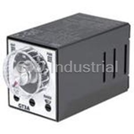
IDEC CORPORATION GT3A-2EAF20
Description
Timer Multi Function 3A Contact Delayed
GT3A-2EAF20
Part Number
GT3A-2EAF20
Price
Request Quote
Manufacturer
IDEC CORPORATION
Lead Time
Request Quote
Category
Tools and Supplies » Timer Instrument
Specifications
Manufacturer
IDEC Corporation
Manufacturers Part #
GT3A-2EAF20
Lead Time
9 Week Lead Time
Sub-Category
Timer Instruments
Factory Pack Quantity
1
Datasheet

Extracted Text
Circuit Breakers Switches & Pilot Lights Switches & Pilot Lights Signaling Lights Signaling Lights Relays & Sockets Relays & Sockets T Timers imers Contactors Contactors T Terminal Blocks erminal Blocks Circuit Breakers GT3A T Timers imers GT3A Series — Analog Timers Key features: • 4 selectable operation modes on each model • External start, reset, and gate inputs • Panel mount or socket mount • Large variety of timing functions • Power and output status indicating LEDs UL, c-UL Listed File No. E55996 Specifications GT3A-1 GT3A-2 GT3A-3 GT3A-4,-5,-6 Operation Multi-mode Multi-mode with inputs (11 pins) Time Range 0.1s to 180 hours 100 to 240V AC, 50/60Hz Rated Voltage 12V DC 24V AC, 50/60Hz / 24V DC 125V AC/250V AC, 3A; 125V AC/250V AC, 5A; Contact Ratings 30V DC, 1A (resistive load) 30V DC, 5A (resistive load) Minimum Applicable Load 5V, 10mA (reference value) AF20 (100V AC): 85 to 264V AC Voltage Tolerance AD24: 20.4 to 26.4V AC/21.6 to 26.4V DC D12: 10.8 to 13.2V DC Error ±0.2%, ±10 msec (repeat, voltage, temperature) Setting Error ±10% maximum Reset Time 60msec maximum Insulation Resistance 100MW minimum Between power and output terminals: 2,000V AC, 1 minute Dielectric Strength Between contacts of different poles: 2,000V AC, 1 minute Between contacts of the same pole: 750V AC, 1 minute Delayed SPDT + Delayed SPDT Delayed DPDT Delayed DPDT instantaneous SPDT 10.8VA 13.5VA 14.4VA 4.7VA (100V AC, 60Hz), Power Consumption (200V AC, 60Hz) (200V AC, 60Hz) (200V AC, 60Hz) 14.4VA (200V AC, 60Hz) (approximate) 12VDC/1W 12VDC/1.1W 12VDC/0.8W — 24VDC/0.7W 24VDC/0.6W 24VDC/0.6W 24VAC/1.2VA 24VAC/1.3VA 24VAC/1.3VA Mechanical Life 10,000,000 operations minimum 5,000,000 operations minimum Electrical LIfe 50,000 operations minimum (rated load) 100,000 operations minimum (rated load) Weight (approximate) 63g 73g 79g 80g 2 Vibration Resistance 100m/sec (approximate 10G) 2 Operating extremes: 100m/sec (approximate 10G) Shock Resistance 2 Damage limits: 500m/sec (approximate 50G) Operating Temperature –10 to +50°C Operating Humidity 45 to 85% RH Storage Temperature –30 to +80°C Housing Color Gray 1705151136 800-262-IDEC (4332) • USA & Canada 951 951 GT3A Timers Part Numbers GT3A-1, -2, -3 Complete Part No. Mode Of Rated Voltage Code Time Range Output Contact Operation 8-Pin 11-Pin AF20: 100 to 240V AC (50/60Hz) Delayed SPDT GT3A-1AF20 GT3A-1EAF20 250V AC, 3A, GT3A-2AF20 GT3A-2EAF20 30V DC, 1A Delayed SPDT + A: ON-delay 1 GT3A-2D12 GT3A-2ED12 (resistive load) Instantaneous SPDT B: Interval 1 0.1 seconds AF20: 100 to 240V AC (50/60Hz) GT3A-2AD24 GT3A-2EAD24 C: Cycle 1 to 180 hours D12: 12V DC GT3A-3AF20 GT3A-3EAF20 D: Cycle 3 AD24: 24V AC (50/60Hz)/24V DC 240V AC, 5A, 24V DC, 5A Delayed DPDT GT3A-3D12 GT3A-3ED12 (resistive load) GT3A-3AD24 GT3A-3EAD24 1. For wiring schematics and timing diagrams for GT3A-1, -2, -3, see pages page 940 and page 941 respectively. 2. For more details about time ranges, see instructions on page page 940. 3. For socket and accessory part numbers, see page 958. GT3A-4, -5, -6 Complete Part No. Mode of Rated Voltage Code Time Range Output Contact Input Operation A (11-pin) B (11-pin) GT3A-4AF20 GT3A-4EAF20 A: ON-Delay 2 AF20: 100 to 240V AC (50/60Hz) B: Cycle 2 D12: 12V DC GT3A-4D12 GT3A-4ED12 C: Signal ON/OFF-Delay 1 AD24: 24V AC (50/60Hz)/24V DC D: Signal OFF-Delay 1 GT3A-4AD24 GT3A-4EAD24 A: Interval 2 GT3A-5AF20 GT3A-5EAF20 250V AC, 5A, Start 0.1 seconds Delayed B: One-Shot Cycle 24V DC, 5A Reset to 180 hours DPDT C: Signal ON/OFF-Delay 2 (resistive load) Gate GT3A-5AD24 GT3A-5EAD24 D: Signal OFF-Delay 2 AF20: 100 to 240V AC (50/60Hz) AD24: 24V AC (50/60Hz)/24V DC A: One-Shot GT3A-6AF20 GT3A-6EAF20 B: One-Shot ON-Delay C: One-Shot 2 GT3A-6AD24 GT3A-6EAD24 D: Signal ON/OFF-Delay 3 4. For wiring schematics and timing diagrams GT3A-4,-5,-6, see pages 940, 941, and 941 respectively. 5. For more details about time ranges, see instructions on page 940. 6. A (11-pin) and B (11-pin) differ in the way inputs are wired. 7. For socket and accessory part numbers, see page 958. 8. For the timing diagrams overview, see page 940. 1705151136 www.IDEC.com 952 Circuit Breakers Terminal Blocks Contactors Timers Relays & Sockets Signaling Lights Switches & Pilot Lights Switches & Pilot Lights Signaling Lights Relays & Sockets Timers Contactors Terminal Blocks Circuit Breakers GT3A Timers Timing Diagrams/Schematics GT3A-1 Timing Diagrams Delayed SPDT Operation Mode Selection Item Terminal Number Operation ON-Delay 1 Set Time T 2 - 7 (8p) Power 2 - 10 (11p) MODE 5 - 8 (8p) (NC) Delayed 8 - 11 (11p) A Contact 6 - 8 (8p) (NO) 9 - 11 (11p) POWER Indicator OUT Item Terminal Number Operation Interval 1 Set Time T 2 - 7 (8p) Power 2 - 10 (11p) MODE 5 - 8 (8p) (NC) 8 - 11 (11p) Delayed B Contact 6 - 8 (8p) (NO) 9 - 11 (11p) POWER Indicator OUT Cycle 1 Item Terminal Number Operation Set Time T T (OFF first) 2 - 7 (8p) Power 2 - 10 (11p) MODE 5 - 8 (8p) (NC) Delayed 8 - 11 (11p) Contact 6 - 8 (8p) C (NO) 9 - 11 (11p) POWER Indicator OUT Cycle 3 Item Terminal Number Operation Set Time T T (ON first) 2 - 7 (8p) Power 2 - 10 (11p) MODE 5 - 8 (8p) (NC) Delayed 8 - 11 (11p) Contact 6 - 8 (8p) D (NO) 9 - 11 (11p) POWER Indicator OUT 1705151136 800-262-IDEC (4332) • USA & Canada 953 GT3A Timers GT3A-2 Timing Diagrams GT3A-3 Timing Diagrams Delayed SPDT + Instantaneous SPDT Delayed DPDT Operation Operation Mode Mode Selection Selection Item Terminal Number Operation Item Terminal Number Operation ON-Delay 1 Set Time T Set Time T 2 - 7 (8p) 2 - 7 (8p) ON-Delay 1 Power Power 2 - 10 (11p) 2 - 10 (11p) MODE 5 - 8 (8p) 1 -4, 5 - 8 (8p) (NC) (NC) Delayed 8 - 11 (11p) Delayed 1 -4, 8 - 11 (11p) MODE A Contact Contact 6 - 8 (8p) 1 -3, 6 - 8 (8p) (NO) (NO) 9 - 11 (11p) 1 -3, 9 - 11 (11p) A 1 - 4 (NC) POWER Instantaneous Indicator Contact 1 - 3 (NO) OUT POWER Indicator OUT Item Terminal Number Operation Interval 1 Set Time T 2 - 7 (8p) Power 2 - 10 (11p) MODE Item Terminal Number Operation 1 -4, 5 - 8 (8p) (NC) 1 -4, 8 - 11 (11p) Set Time T Delayed B 2 - 7 (8p) Contact 1 -3, 6 - 8 (8p) Interval 1 Power (NO) 2 - 10 (11p) 1 -3, 9 - 11 (11p) 5 - 8 (8p) (NC) POWER 8 - 11 (11p) MODE Delayed Indicator Contact 6 - 8 (8p) (NO) OUT 9 - 11 (11p) B 1 - 4 (NC) Instantaneous Contact 1 - 3 (NO) Cycle 1 Item Terminal Number Operation Set Time T T POWER (OFF first) 2 - 7 (8p) Indicator Power 2 - 10 (11p) OUT MODE 1 -4, 5 - 8 (8p) (NC) Delayed 1 -4, 8 - 11 (11p) Contact 1 -3, 6 - 8 (8p) C (NO) 1 -3, 9 - 11 (11p) Item Terminal Number Operation Set Time T T POWER Cycle 1 Indicator 2 - 7 (8p) Power 2 - 10 (11p) OUT (OFF first) 5 - 8 (8p) (NC) Delayed 8 - 11 (11p) MODE Contact 6 - 8 (8p) (NO) 9 - 11 (11p) Cycle 3 Item Terminal Number Operation C 1 - 4 (NC) Instantaneous Set Time T T (ON first) Contact 2 - 7 (8p) 1 - 3 (NO) Power 2 - 10 (11p) MODE 1 -4, 5 - 8 (8p) POWER (NC) 1 -4, 8 - 11 (11p) Delayed Indicator Contact 1 -3, 6 - 8 (8p) OUT D (NO) 1 -3, 9 - 11 (11p) POWER Indicator OUT Item Terminal Number Operation Set Time T T Cycle 3 2 - 7 (8p) Power 2 - 10 (11p) (ON first) 5 - 8 (8p) (NC) 8 - 11 (11p) Delayed MODE Contact 6 - 8 (8p) (NO) 9 - 11 (11p) D 1 - 4 (NC) Instantaneous Contact 1 - 3 (NO) POWER Indicator OUT Note: Pins 1, 3, and 4 are the instantaneous contacts. 1705151136 www.IDEC.com 954 Circuit Breakers Terminal Blocks Contactors Timers Relays & Sockets Signaling Lights Switches & Pilot Lights Switches & Pilot Lights Signaling Lights Relays & Sockets Timers Contactors Terminal Blocks Circuit Breakers GT3A Timers GT3A-4 Timing Diagrams Delayed DPDT Operation Mode Selection Item Terminal Number Operation Power 2 - 10 POWER 2 - 6 (A) Start ON or L ON-Delay 2 5 - 7 (B) 2 - 7 (A) Input Reset ON or L 6 - 7 (B) MODE Gate 2 - 5 (A) ON or L 1 - 4 A (NC) 8 - 11 Delayed Contact 1 - 3 (NO) 9 - 11 POWER Indicator OUT Set Time T Ta T' T" Item Terminal Number Operation Power 2 - 10 POWER 2 - 6 (A) Start ON or L Cycle 2 5 - 7 (B) 2 - 7 (A) Input Reset ON or L 6 - 7 (B) MODE Gate 2 - 5 (A) ON or L 1 - 4 B (NC) 8 - 11 Delayed Contact 1 - 3 (NO) 9 - 11 POWER Indicator OUT Set Time T T T T T T T Ta T T T T" T" T T T T T Item Terminal Number Operation Power 2 - 10 POWER 2 - 6 (A) Start ON or L Signal ON/OFF-Delay 1 5 - 7 (B) 2 - 7 (A) Input Reset ON or L 6 - 7 (B) MODE Gate 2 - 5 (A) ON or L 1 - 4 C (NC) 8 - 11 Delayed Contact 1 - 3 (NO) 9 - 11 POWER Indicator OUT Set Time T T Ta T Ta T T T T" Ta Item Terminal Number Operation Power 2 - 10 POWER 2 - 6 (A) Start ON or L Signal OFF-Delay 1 5 - 7 (B) 2 - 7 (A) Input Reset ON or L 6 - 7 (B) MODE Gate 2 - 5 (A) ON or L 1 - 4 D (NC) 8 - 11 Delayed Contact 1 - 3 (NO) 9 - 11 POWER Indicator OUT Set Time T Ta Ta T T T T = Set time Ta = Shorter than set time T = T' + T" 1705151136 800-262-IDEC (4332) • USA & Canada 955 GT3A Timers GT3A-5 Timing Diagrams Delayed DPDT Operation Mode Selection Item Terminal Number Operation Power 2 - 10 POWER 2 - 6 (A) Start ON or L Interval 2 5 - 7 (B) 2 - 7 (A) Input Reset ON or L 6 - 7 (B) MODE Gate 2 - 5 (A) ON or L 1 - 4 A (NC) 8 - 11 Delayed Contact 1 - 3 (NO) 9 - 11 POWER Indicator OUT Set Time T Ta T' T" Item Terminal Number Operation Power 2 - 10 POWER 2 - 6 (A) Start ON or L One-Shot Cycle 5 - 7 (B) 2 - 7 (A) Input Reset ON or L 6 - 7 (B) MODE Gate 2 - 5 (A) ON or L 1 - 4 B (NC) 8 - 11 Delayed Contact 1 - 3 (NO) 9 - 11 POWER Indicator OUT Set Time T T T Ta T' T" T Item Terminal Number Operation Power 2 - 10 POWER 2 - 6 (A) Start ON or L Signal ON/OFF-Delay 2 5 - 7 (B) 2 - 7 (A) Input Reset ON or L 6 - 7 (B) MODE Gate 2 - 5 (A) ON or L 1 - 4 C (NC) 8 - 11 Delayed Contact 1 - 3 (NO) 9 - 11 POWER Indicator OUT Set Time T T Ta T Ta Ta T T' T" Ta Item Terminal Number Operation Power 2 - 10 POWER 2 - 6 (A) Start ON or L Signal OFF-Delay 2 5 - 7 (B) 2 - 7 (A) Input Reset ON or L 6 - 7 (B) MODE Gate 2 - 5 (A) ON or L 1 - 4 D (NC) 8 - 11 Delayed Contact 1 - 3 (NO) 9 - 11 POWER Indicator OUT Set Time T Ta Ta T T' T" T = Set time Ta = Shorter than set time T = T' + T" 1705151136 www.IDEC.com 956 Circuit Breakers Terminal Blocks Contactors Timers Relays & Sockets Signaling Lights Switches & Pilot Lights Switches & Pilot Lights Signaling Lights Relays & Sockets Timers Contactors Terminal Blocks Circuit Breakers GT3A Timers GT3A-6 Timing Diagrams Delayed DPDT Operation Mode Selection Item Terminal Number Operation Power 2 - 10 POWER 2 - 6 (A) Start ON or L One-Shot 1 5 - 7 (B) 2 - 7 (A) Input Reset ON or L 6 - 7 (B) MODE Gate 2 - 5 (A) ON or L 1 - 4 A (NC) 8 - 11 Delayed Contact 1 - 3 (NO) 9 - 11 POWER Indicator OUT Set Time Ta Ta T Ta T' T" Item Terminal Number Operation Power 2 - 10 POWER 2 - 6 (A) Start ON or L One-Shot ON-Delay 5 - 7 (B) 2 - 7 (A) Input Reset ON or L 6 - 7 (B) MODE Gate 2 - 5 (A) ON or L 1 - 4 B (NC) 8 - 11 Delayed Contact 1 - 3 (NO) 9 - 11 POWER Indicator OUT Set Time T T Ta T T T' T" Item Terminal Number Operation Power 2 - 10 POWER 2 - 6 (A) Start ON or L One-Shot 2 5 - 7 (B) 2 - 7 (A) Input Reset ON or L 6 - 7 (B) MODE Gate 2 - 5 (A) ON or L 1 - 4 C (NC) 8 - 11 Delayed Contact 1 - 3 (NO) 9 - 11 POWER Indicator OUT Set Time T Ta T T' T" Item Terminal Number Operation Power 2 - 10 POWER 2 - 6 (A) Start ON or L Signal ON/OFF-Delay 3 5 - 7 (B) 2 - 7 (A) Input Reset ON or L 6 - 7 (B) MODE Gate 2 - 5 (A) ON or L 1 - 4 D (NC) 8 - 11 Delayed Contact 1 - 3 (NO) 9 - 11 POWER Indicator OUT Set Time T T Ta T' T" Ta Ta T T = Set time Ta = Shorter than set time T = T' + T" 1705151136 800-262-IDEC (4332) • USA & Canada 957 GT3A Timers Instructions: Setting GT3A Series Timers Timed OUT Indicator POWER Indicator (flashes during time-delay period) m Setting Knob j Operator Mode Selector l Time Range Selector A, B, C, D 1S, 10S, 10M, 10H k Dial Selector 0-1, 0-3, 0-6, 0-18 Step 1. Desired Mode of Operation Selection Remarks For Timers Mode of Operation j Operation Mode Selector ON-delay 1 A GT3A-1 Interval 1 B GT3A-2 Cycle 1 C GT3A-3 Cycle 3 D ON-delay 2 A The desired operation mode can be selected from Cycle 2 B the A, B, C, and D modes using the Operation Mode GT3A-4 Signal ON/OFF-delay 1 C Selector. Change the operation mode from A to B, C, Select the desired mode Signal OFF-delay 1 D and D in turn by turning the operation mode selector of operation. clockwise using a flat screwdriver which is a maximum Interval 2 A of 0.156” (4mm) wide. The selected mode is displayed One-shot cycle B GT3A-5 in the window. Signal ON/OFF-delay 2 C Signal OFF-delay 2 D One-shot 1 A One-shot ON-delay B GT3A-6 One-shot 2 C Signal ON/OFF-delay 3 D Step 2. Desired Time Range Selection Remarks Time Ranges k Dial Selector l Time Range Selector 0.1 seconds to 1 second 0-1 0.1 seconds to 3 seconds 0-3 1S 0.1 seconds to 6 seconds 0-6 0.15 seconds to 18 seconds 0-18 0.1 seconds to 10 seconds 0-1 0.3 seconds to 30 seconds 0-3 10S 0.6 seconds to 60 seconds 0-6 Select the time range The desired time range is selected by setting both that contains the desired k Dial Selector and 1.8 seconds to 180 seconds 0-18 time period. l Time Range Selector. 6 seconds to 10 minutes 0-1 18 seconds to 30 minutes 0-3 10M 36 seconds to 60 minutes 0-6 108 seconds to 180 minutes 0-18 6 minutes to 10 hours 0-1 18 minutes to 30 hours 0-3 10H 36 minutes to 60 hours 0-6 108 minutes to 180 hours 0-18 Step 3. Selection Set the precise period of time desired by using the m Setting Knob. 1705151136 www.IDEC.com 958 Circuit Breakers Terminal Blocks Contactors Timers Relays & Sockets Signaling Lights Switches & Pilot Lights Switches & Pilot Lights Signaling Lights Relays & Sockets Timers Contactors Terminal Blocks Circuit Breakers GT3F Timers GT3F Series — True Power OFF Delay Timers Key features: • “True” power OFF-delay up to 10 minutes • No external control switch necessary • Available with reset inputs • Mountable in sockets or flush panel UL, c-UL Listed File No. E55996 Specifications GT3F-1 GT3F-2 Operation True power OFF-delay Time Range 0.1 seconds to 600 seconds 100 to 240V AC, 50/60Hz Rated Voltage 24V AC/DC 250V AC/24V DC, 5A 250V AC/24V DC, 3A Contact Rating (resistive load) (resistive load) Contact Form SPDT DPDT Minimum Power Application Time 1 second AF20: 100 to 240V AC Voltage Tolerance AD24: 21.6 to 26.4VDC, 20.4 to 26.4VAC Repeat Error ±0.2%, ±10 msec Voltage Error ±0.2%, ±10 msec Temperature Error ±0.2%, ±10 msec Setting Error ±10% maximum Insulation Resistance 100MW minimum Between power and output terminals: 2,000V AC, 1 minute (SPDT) 1,500V AC, 1 minute (DPDT) Dielectric Strength Between contacts on different poles: 1,000V AC, 1 minute (DPDT) Between contacts of the same pole: 750V AC, 1 minute AF20: 3.7VA (200V AC, 60Hz) Power Consumption AD24: 0.8W (DC), 1.2VA (AC) Mechanical Life 3,000,000 operations minimum Electrical Life 100,000 operations minimum 2 Vibration Resistance 100m/sec (approximate 10G) Operating extremes: 2 Shock Resistance 100 m/sec (approximate 10G) 2 Damage limits: 500 m/sec (approximate 50G) Operating Temperature –10 to +50°C Storage Temperature –30 to +80°C Operating Humidity 45 to 85% RH Weight (approximate) 77g 79g 1. An inrush current flows during the minimum power application time. AF20: approximate 0.4A, AD24: approximate 1.2A 2. GT3F does not read the preset time range shown on the knob after power is turned off. Note that minimizing the preset time, by turning the knob to zero, does not shorten the delay time after power is removed. 1705151136 800-262-IDEC (4332) • USA & Canada 959 GT3F Timers Part Numbering List GT3F Complete Part Number Mode of Rated Time Range Output Contact Optional Input Operation Voltage Code 8-Pin 11-Pin 250V AC, 5A, GT3F-1AF20 GT3F-1EAF20 AF20: 100 to Delayed SPDT Reset 240VAC (50/60Hz) 30V DC, 5A (resistive load) GT3F-1AD24 GT3F-1EAD24 True-Power 0.1 seconds to OFF-delay 600 seconds 250V AC, 3A, GT3F-2AF20 GT3F-2EAF20 None (8p) AD24: 24V AC/DC Delayed DPDT Reset (11p) 30V DC, 3A (resistive load) GT3F-2AD24 GT3F-2EAD24 Optional reset input resets the contact to the OFF state before time out. Timing Diagrams/Schematics GT3F-1 Timing Diagrams GT3F-1 (8-pin) GT3F-1E (11-pin) Delayed SPDT Output, with Reset Input Item Terminal Number Operation 2 - 7 (8p) Power 2 - 10 (11p) Reset 1 - 4 (8p) ON or L Input 6 - 7 (11p) 5 - 8 (8p) (NC) 1 - 4 (11p) Delayed Contact 6 - 8 (8p) (NO) 1 - 3 (11p) Indicator POWER Set Time Tr T Ta Ts T T = Set time 1. For time ranges, see page page 941. Ta = Shorter than set time 2. For sockets and accessory part numbers, see page page 967. Ts = 1 Second 3. When power is applied, the NO output contact closes. When power is removed, the timing period Tr = Minimum Power Application Time begins. When time has elapsed, the NO contact opens. GT3F-1: 1 Second 4. For the timing diagram overview, see page page 940. 1705151136 www.IDEC.com 960 Circuit Breakers Terminal Blocks Contactors Timers Relays & Sockets Signaling Lights Switches & Pilot Lights Switches & Pilot Lights Signaling Lights Relays & Sockets Timers Contactors Terminal Blocks Circuit Breakers GT3F Timers GT3F-2 Timing Diagrams GT3F-2 (8-pin) GT3F-2E (11-pin) Delayed DPDT Output (Contact Input) (Transistor Input) (-) (+) (-) (+) (-) (+) POWER POWER POWER Item Terminal Number Operation Power 2 - 7 1 - 4 (NC) 5 - 8 Delayed Contact 1 - 3 8-Pin Type (NO) 6 - 8 Indicator POWER Set Time T Tr T Item Terminal Number Operation Power 2 - 10 Reset 6 - 7 (11p) ON or L Input 1 - 4 (NC) 8 - 11 Delayed 11-Pin Type Contact 1 - 3 (NO) 9 - 11 Indicator POWER Set Time Tr T Ta Ts T When power is applied, the NO contact closes. When power is removed, the timing period begins. When time has elapsed, the NO contact opens. Optional reset input will return contacts to original state before time elapses. T = Set time Ta = Shorter than set time Ts = 1 Second Tr = Minimum Power Application Time GT3F-1: 1 Second Item Terminal Number Operation Power 2 - 10 Reset 6 - 7 (11p) ON or L Input 1 - 4 (NC) 8 - 11 Delayed Contact 1 - 3 (NO) 9 - 11 Indicator POWER Set Time Tr T Ta Ts T 1705151136 800-262-IDEC (4332) • USA & Canada 961 GT3F Timers Instructions: Setting GT3F Series Timers POWER Indicator l Setting Knob k Time Range Selector j Dial Selector 1S, 10S 0-1, 0-3, 0-6, 0-18, 0-60 Step 1 Desired Operation Selection Remarks k Time Range Base Time Ranges j Dial Selector Selector 0.1s to 1s 0 to 1 0.1s to 3s 0 to 3 1s Select a time Time range can be selected from 1S and 10S using a flat screwdriver and five different range that 0.1s to 6s 0 to 6 dials of 0 to 1, 0 to 3, 0 to 6, 0 to 18, and 0 to 60 are displayed in the six windows by contains the turning the Dial Selector, allowing for selecting the best suited scale. Note that the 0.1s to 10s 0 to 1 desired period switch does not turn infinitely. 0.3s to 30 0 to 3 of time. 0.6s to 60 0 to 6 10s 1.8s to 180s 0 to 18 6s to 600s 0 to 60 Step 2 Remarks Setting Examples: 1. When the Setting Knob l is set at 2.5, with Dial Selector j 0 to 3 and Time Range The set time is selected by turning the l Setting Knob. Selector k 1S selected, then the set time is 2.5 seconds. 2. When the Setting Knob l is set at 5.0, with Dial Selector j 0 to 60 and Time Range Selector k 10S selected, then the set time is 500 seconds. Instructions: Wiring Inputs Inputs of GT3F To avoid electric shock, do not touch the input signal terminal during power voltage application. Never apply the input signals to two or more GT3F timers using the same contact or transistor. [Incorrect] GT3 Series Input Timer [correct] Contact or Transistor Input Input Terminal Terminal 2 10 2 10 Power Power Input Input Terminal Terminal 2 10 2 10 In a transistor circuit for controlling input signals, with its primary and secondary power circuits isolated, do not ground the secondary circuit. GT3 Series Timer Input Terminal Power Circuit Insulating Transformer On the GT3F timers, connect the input signals to terminal No.1 and 4 only on the 8-pin type; connect the input signals to terminal No. 6 and 7 only on the 11-pin type. Never apply voltage to other terminals; otherwise, the internal circuit may be damaged. Input signal lines must be made as short as possible and installed away from power cables and power lines. Use shielded wires or a separate conduit for input wiring. The GT3F, consisting of a high-impedance circuit, may not be reset due to the influence of an inductive voltage or residual voltage caused by a leakage current. If not reset, connect an RC filter or bleeder resistor between power terminals so that the voltage between power terminals can be reduced to less than 15% of the rated voltage. 1705151136 www.IDEC.com 962 Circuit Breakers Terminal Blocks Contactors Timers Relays & Sockets Signaling Lights Switches & Pilot Lights Rectifier Circuit Switches & Pilot Lights Signaling Lights Relays & Sockets Timers Contactors Terminal Blocks Circuit Breakers GT3W Timers GT3W Series — Dual Time Range Timers Key features: • Sequential start, sequential interval, on-delay, recycler, and interval ON timing functions • 2 time settings in one timer • 8 selectable operation modes on each model • Mountable in sockets or flush panel • Power and output status indicating LEDs • Time ranges up to 300 hours UL, c-UL Listed File No. E55996 General Specifications Contact Ratings Operation System Solid state CMOS Circuit Allowable Contact Power 960VA/120W Operation Type Multi-Mode Allowable Voltage 250V AC/150V DC Time Range 1: 0.1sec to 6 hours, 3: 0.1sec to 300 hours Allowable Current 5A Pollution Degree 2 (IE60664-1) Maximum permissible 1800 cycles per hour Over Voltage Category III (IE60664-1) operating frequency AF20 100-240V AC(50/60Hz) 1/8HP, 240V AC Rated Operational Voltage AD24 24V AC(50/60Hz)/24V DC 3A, 240V AC (Resistive) Rated Load D12 12V DC 5A, 120V AC/30V DC AF20 85-264V AC(50/60Hz) (Resistive) Voltage Tolerance AD24 20.4-26.4V AC(50/60Hz)/21.6-26.4V DC Conditional Short Circuit Fuse 5A, 250V D12 10.8-13.2V DC 100,000 op. minimum Electrical Disengaging Value of Input Voltage Rated Voltage x10% minimum (Resistive) Life Range of Ambient Operating Temperature -10 to +50ºC (without freezing) Mechanical 20,000,000 op. minimum Range of Ambient Storage -30 to +75ºC (without freezing) and Transport Temperature Range of Relative Humidity 35 to 85%RH (without condensation) Atmospheric Pressure 80kPa to 110kPa (Operating), 70kPa to 110kPa (Transport) Reset Time 60msec maximum Repeat Error ±0.2%, ±10msec* Voltage Error ±0.2%, ±10msec* Temperature Error ±0.6%, ±10msec* Setting Error ±10% maximum Insulation Resistance 100MΩ minimum (500V DC) Between power and output terminals: 2000V AC, 1 minute Dielectric Strength Between contacts of different poles: 2000V AC, 1 minute Between contacts of the same pole:750V AC, 1 minute 2 Vibration Resistance 10 to 55Hz amplitude 0.75mm hours in each of 3 axes 2 Operating extremes: 98m/sec (approx.10G) 2 Shock Resistance Damage limits: 490m/sec (approx. 50G) 3 times in each of 3 axes Degree of Protection IP40 (enclosure), IP20 (socket) (IEC60529) 100V AC/60Hz 2.3VA AF20 Power Consumption 200V AC/60Hz 4.6VA (Approx.) AD24 (AC/DC) 1.8VA/0.9W Mounting Position Free Dimensions 40Hx 36W x 70 mm Weight (Approx.) 72g * For the value of the error against a preset time, whichever the largest applies. 1705151136 800-262-IDEC (4332) • USA & Canada 963 GT3W Timers Part Number List Part Numbers Mode of Operation Output Contact Time Range* Rated Voltage Pin Configuration New Part Numbers 8 pin GT3W-A11AF20N 100 to 240V AC (50/60Hz) 11 pin GT3W-A11EAF20N A: Sequential Start 8 pin GT3W-A11AD24N 1: 0.1sec - 6 hours B: On-delay with course and fine *(See Time Range 24V AC/DC C: Recycler and instaneous Delayed 3A, 240V AC Settings for details.) 11 pin GT3W-A11EAD24N D: Recycler outputs (OFF Start) SPDT E: Recycler outputs (ON Start) + 5A, 120V AC/30V DC F: Interval ON Delayed 8 pin GT3W-A11D12N (Resistive Load) G: Interval ON Delay SPDT 12V DC H: Sequential 11 pin GT3W-A11ED12N Interval 100 to 240V AC GT3W-A33AF20N (50/60Hz) 3: 0.1sec - 300 hours 8 pin 24V AC/DC GT3W-A33AD24N 1. For timing diagrams and schematics, see page 940. 2. For socket and accessory part number information, see page 959. 3. 8- and 11-pin models differ only in the number of pins (extra pins are not used). 4. For the timing diagram overview, see page 940. 5. *For details on setting time ranges, see the instructions on page 941. Time Range Table Time Range Code: 1 Time Range Code: 3 Time Range Time Range Scale Time Range Scale Time Range Selector Selector 1S 0.1 sec - 1 sec 1S 0.1 sec - 3 sec 10S 0-1 0.3 sec - 10 sec 1M 0 - 3 3 sec - 3 min 10M 15 sec - 10 min 1H 3 min - 3 hours 1S 0.1 sec - 6 sec 1S 0.6 sec - 30 sec 10S 1 sec - 60 sec 1M 36 sec - 30 min 1M 0 - 6 6 sec - 6 min 1H 0 - 30 36min - 30 hours 10M 1 min - 60 min 10H 6 hours - 300 hours 1H 6 min - 6 hours 1705151136 www.IDEC.com 964 Circuit Breakers Terminal Blocks Contactors Timers Relays & Sockets Signaling Lights Switches & Pilot Lights Switches & Pilot Lights Signaling Lights Relays & Sockets Timers Contactors Terminal Blocks Circuit Breakers GT3W Timers Timing Diagrams/Schematics Mode Operation Chart Mode Operation Chart Terminal Terminal Item Operation Description Item Operation Description No. No. Power 2-7 Power 2-7 1-4 1-4 Delayed Delayed (NC) (NC) ON during T1 Contact Contact 1-3 1-3 OFF during T2 Ry1 ON after T1 Ry1 (NO) (NO) 5-8 5-8 Delayed Delayed (NC) (NC) ON during T1 Contact Contact 6-8 6-8 OFF during T2 Ry2 ON after T1 + T2 Ry2 (NO) (NO) OUT1 OUT1 Indicator Indicator OUT2 OUT2 Set Time Set Time T1 T2 T1 T2 Terminal Terminal Item Operation Description Item Operation Description No. No. Power 2-7 Power 2-7 1-4 1-4 Delayed Delayed (NC) (NC) Contact Contact 1-3 1-3 Ry1 Ry1 ON after T1 + T2 ON during T1 (NO) (NO) 5-8 5-8 Delayed Delayed (NC) (NC) ON after T1, Contact Contact 6-8 6-8 during T2 Ry2 ON after T1 + T2 Ry2 (NO) (NO) OUT1 OUT1 Indicator Indicator OUT2 OUT2 Set Time Set Time T1 T2 T1 T2 Terminal Terminal Item Operation Description Item Operation Description No. No. Power 2-7 Power 2-7 1-4 1-4 Delayed Delayed (NC) (NC) Contact Contact 1-3 1-3 Ry1 Instantaneous ON Ry1 ON during T1 (NO) (NO) 5-8 5-8 Delayed Delayed (NC) (NC) OFF during T1 Contact Contact 6-8 6-8 ON during T2 Ry2 Ry2 ON after T1 + T2 (NO) (NO) OUT1 OUT1 Indicator Indicator OUT2 OUT2 Set Time Set Time T1 T2 T1 T2 Terminal Terminal Item Operation Description Item Operation Description No. No. Power 2-7 Power 2-7 1-4 1-4 Delayed Delayed (NC) (NC) OFF during T1 Contact Contact 1-3 1-3 ON during T2 Ry1 Ry1 ON during T1 + T2 (NO) (NO) 5-8 5-8 Delayed Delayed (NC) (NC) OFF during T1 ON after T1, Contact Contact 6-8 6-8 ON during T2 during T2 Ry2 Ry2 (NO) (NO) OUT1 OUT1 Indicator Indicator OUT2 OUT2 Set Time Set Time T1 T2 T1 T2 1705151136 800-262-IDEC (4332) • USA & Canada 965 D: Recycler outputs (OFF Start) C: Recycler and instantaneous B: On-delay with course and fine A: Sequential Start H: Sequential Interval G: Interval ON Delay F: Interval ON E: Recycler outputs (ON Start) GT3W Timers Instructions: Setting GT3W Timer T2 Setting Knob 1. The switches should be securely turned using a flat screwdriver 4mm T2 Time Range Selector wide (maximum). Note that incorrect setting may cause malfunction. The switches, which do not turn infinitely, should not be turned beyond Operation Mode Selector their limits. T1 Setting Knob 2. Since changing the setting during timer operation my cause malfunction, T1 Time Range Selector turn power off before changing. Safety Precautions Special expertise is required to use Electronic Timers. Caution • All Electronic Timer modules are manufactured under IDEC’s rigorous quality Caution notices are used where inattention might cause personal injury or dam- control system, but users must add a backup or fail safe provision to the age to equipment. control system when using the Electronic Timer in applications where heavy • The Electronic Timer is designed for installation in equipment. Do not install damage or personal injury may occur should the Electronic Timer fail. the Electronic Timer outside equipment. • Install the Electronic Timer according to instructions described in this catalog. • Install the Electronic Timer in environments described in the specifications. If • Make sure that the operating conditions are as described in the specifica- the Electronic Timer is used in places where it will be subjected to high-tem- tions. If you are uncertain about the specifications, contact IDEC in advance. perature, high-humidity, condensation, corrosive gases, excessive vibrations, or excessive shocks, then electrical shocks, fire hazard, or malfunction could • In these directions, safety precautions are categorized in order of importance result. to Warning and Caution. • Use an IEC60127-approved fuse and circuit breaker on the power and output line outside the Electronic Timer. Warning • Do not disassemble, repair, or modify the Electronic Timer. Warning notices are used to emphasize that improper operation may cause sever personal injury or death. • When disposing of the Electronic Timer, do so as industrial waste. • Turn power off to the Electronic timer before starting installation, removal, Wiring, maintenance, and inspection on the Electronic Timer. • Failure to turn power off may cause electrical shocks or fire hazard. • Emergency stop and interlocking circuits must be configured outside the Electronic timer. If such a circuit is configured inside the Electronic Timer, failure of the Electronic timer may cause malfunction of the control system, or an accident. 1705151136 www.IDEC.com 966 Circuit Breakers Terminal Blocks Contactors Timers Relays & Sockets Signaling Lights Switches & Pilot Lights Switches & Pilot Lights Signaling Lights Relays & Sockets Timers Contactors Terminal Blocks Circuit Breakers GT3 Series Accessories Timers GT3 Series Accessories DIN Rail Mounting Accessories DIN Rail/Surface Mount Sockets and Hold-Down Springs DIN Rail Mount Socket Applicable Hold-Down Springs Style Appearance Use with Timers Part No. Appearance Part No. GT3A-1, 2, 3 (8-pin) 8-Pin Screw Terminal GT3F-1, 2 (8-pin) SR2P-05 (dual tier) GT3W (8-pin) GT3A-1, 2, 3 (11-pin) 11-Pin Screw Terminal GT3A-4, 5, 6 SR3P-05 (dual tier) GT3F-1, 2 (11-pin) GT3W (11-pin) SFA-203 GT3A-1, 2, 3 (8-pin) 8-Pin Fingersafe Socket GT3F-1, 2 (8-pin) SR2P-05C GT3W (8-pin) GT3A-1, 2, 3 (11-pin) GT3A-4, 5, 6 11-Pin Fingersafe Socket SR3P-05C GT3F-1, 2 (11-pin) GT3W (11-pin) GT3A-1, 2, 3 (8-pin) 8-Pin Screw Terminal GT3F-1, 2 (8-pin) SR2P-06 GT3W (8-pin) SFA-202 GT3A-1, 2, 3 (11-pin) GT3A-4, 5, 6 11-Pin Screw Terminal SR3P-06 GT3F-1, 2 (11-pin) GT3W (11-pin) DIN Mounting Rail — BNDN1000 Length 1000mm Installation of Hold-Down Springs DIN Rail Mount Socket Panel Mount Socket Insert the springs into the outer Hold-down Spring slots with the projections Insert the springs facing inside. SFA-402 into the slots. Insert 8-pin Socket Socket SR2P-05 Hold-down Spring (sold separately) SR2P-51 SFA-203 (use two springs) Socket SR2P-06 Hold-down Spring (sold separately) SFA-202 (use two springs) 1705151136 800-262-IDEC (4332) • USA & Canada 967 GT3 Series Accessories Timers Panel Mounting Accessories Panel Mount Sockets and Hold-Down Springs Panel Mount Socket Applicable HD Springs Style Appearance Use with Timers Part No. Appearance Part No. GT3A- (8-pin) 8-Pin Solder Terminal GT3W- (8-pin) SR2P-51 GT3F- (8-pin) SFA-402 GT3A- (11-pin) 11-Pin Solder Terminal GT3W- (11-pin) SR3P-51 GT3F- (11-pin) For information on installing the hold-down springs, see page 967. Flush Panel Mount Adapter and Sockets that use an Adapter Accessory Description Appearance Use with Timers Part No. Panel Mount Adapter Adaptor for flush panel mounting GT3 timers All GT3 timers RTB-G01 8-pin screw terminal All 8-pin timers SR6P-M08G (Shown: SR6P-M08G for Wiring Socket Adapter) 11-pin screw terminal All 11-pin timers SR6P-M11G Sockets for use with Panel Mount Adapter 8-pin solder terminal All 8-pin timers SR6P-S08 11-pin solder terminal All 11-pin timers SR6P-S11 No hold down springs are available for flush panel mounting. 1705151136 www.IDEC.com 968 Circuit Breakers Terminal Blocks Contactors Timers Relays & Sockets Signaling Lights Switches & Pilot Lights Switches & Pilot Lights Signaling Lights Relays & Sockets Timers Contactors Terminal Blocks Circuit Breakers GT3 Series Instructions Timers Instructions: Wiring Inputs for GT3 Series Inputs To avoid electric shock, do not touch the input signal terminal during power voltage application. When connecting the input signal terminals of two or more GT3A timers to the same contact or transistor, the input terminals of the same number should be con- nected. (Connect Terminals No.2 in common.) [Incorrect] GT3 Series Input Timer [correct] Contact or Transistor Input Input Terminal Terminal 2 10 2 10 Power Power Input Input Terminal Terminal 2 10 2 10 In a transistor circuit for controlling input signals, with its primary and secondary power circuits isolated, do not ground the secondary circuit. GT3 Series Timer Input Terminal Power Circuit Insulating Transformer Connect the input signal terminals of the GT3A timers to Terminal No.2 only. Never apply voltage to other terminals; otherwise, the internal circuit may be damaged. R Y 5, 6, and 7 Input Terminal 210 Power Input signal lines must be made as short as possible and installed away from power cables and power lines. Use shielded wires or a separate conduit for input wiring. 1705151136 800-262-IDEC (4332) • USA & Canada 969 Rectifier Circuit GT3 Series Instructions Timers Inputs Instructions, continued For contact input, use gold-plated contacts to make sure that the residual voltage is less than 1V when the contacts are closed. 6 5 7 4 8 3 9 2 10 111 Power For transistor input, use transistors with the following specifications; VCE = 40V, VCES = 1V or less, IC = 50 mA or more, and ICBO = 50µA or less. The resistance should be less than 1kΩ when the transistor is on. When the output transistor switches on, a signal is input to the timer. 6 5 7 4 8 3 9 2 10 111 Power Inputs: GT3A-1, -2, -3 Transistor output equipment such as proximity switches and photoelectric switches can input signals if they are voltage/current output type, with power voltage ranges from 18 to 30V and have1V. When the signal voltage switches from H to L, a signal is input to the timer 6 5 7 4 8 3 9 2 10 111 Power Inputs: GT3A-4, -5, -6 The start input initiates a time-delay operation and controls No-voltage contact inputs and NPN open collector Start Input output status. transistor inputs are applicable. When the reset input is activated, the time is reset, and Reset Input contacts return to original state. 24V DC, 1mA maximum The time-delay operation is suspended while the gate input Gate Input Input response time: 50msec maximum is on (pause). 1705151136 www.IDEC.com 970 Circuit Breakers Terminal Blocks Contactors Timers Relays & Sockets Signaling Lights Switches & Pilot Lights Reset Input Reset Input Reset Input Start Input Start Input Gate Input Start Input Gate Input Gate Input Switches & Pilot Lights Signaling Lights Relays & Sockets Timers Contactors Terminal Blocks Circuit Breakers GT3 Series Dimensions Timers Dimensions 70.0 36.0 5.6 Unit: mm NOTE: GT3W series are UL Listed when used in combination with following IDEC’s sockets: GT3W-A11, A33: SR2P-06* pin type socket. GT3W-A11E: SR3P-05* pin type socket. (*-May be followed by A,B,C or U) The socket to be used with these timers are rated: -Conductor Temperature Rating 60ºC min. 2 -Use 14AWG max.(2mm max.) Copper conductors only -Terminal Torque 1.0 to 1.3 N-m Analog GT3 Timer, 8-Pin with SR2P-06 Analog GT3 Timer, 11-Pin with SR3P-06 (When using DIN Rail) Analog Setting Type When using BAA/BAP: 99 maximum (When using DIN Rail) Analog Setting Type When using BAA/BAP: 99 maximum 95 maximum 95 maximum Hold- DIN Rail down Hold- spring DIN Rail down ( ) SFA-202 spring 18 (SFA-202) 18 36 8 64.2 13 22 36 8 64.2 13 22 Analog GT3 Timer, 11-Pin with SR3P-05 (When using DIN Rail) Analog Setting Type BAA or BAP: 105.5 maximum DIN Rail 101.5 maximum (BAA/BAP/BADA) Hold-down Spring (SFA-203) 16.5 20 36 8 64.213 28.5 Panel Mount Adapter Analog GT3 Timer, 8-Pin and 11-Pin with SR6P-S08 or SR6P-S11 98 maximum Panel Thickness 0.8 to 5mm Back Wiring Socket 48 11 61.2 1705151136 800-262-IDEC (4332) • USA & Canada 971 40 40 48 33 ø27 1.7 N40.0 42.5 1.7 3 52 31.7 60 1 40 1.7 31.7 60 1 GT3 Series Dimensions Timers Mounting Hole Layout Single Tolerance: +0.5 to 0 Horizontal Close Mounting Mounting N: No. of timers mounted 45 48N--3 GT3 Timer, 8-Pin with SR6P-M08G GT3 Timer, 11-Pin with SR6P-M11G 8-M3.5 Terminal Screw 11-M3.5 Teminal Screws Panel Thickness 0.8 to 5mm 44.6 45 16.7 3.5 max.5.6 min. 5.8 min. ø3.6 min. 3.5 max. 34 56 2 1 11 7 6 ø3.6 min. 5 6.9 max. 2187 6.9 max. 4 3 8 9 10 7 30.5 7 9.8 × 3 80.5 92 8.5 × 4 1705151136 www.IDEC.com 972 Circuit Breakers Terminal Blocks Contactors Timers Relays & Sockets Signaling Lights Switches & Pilot Lights 44.6 45 30.4 45 45 34
Frequently asked questions
How does Electronics Finder differ from its competitors?

Is there a warranty for the GT3A-2EAF20?
Which carrier will Electronics Finder use to ship my parts?
Can I buy parts from Electronics Finder if I am outside the USA?
Which payment methods does Electronics Finder accept?
Why buy from GID?

Quality
We are industry veterans who take pride in our work

Protection
Avoid the dangers of risky trading in the gray market

Access
Our network of suppliers is ready and at your disposal

Savings
Maintain legacy systems to prevent costly downtime

Speed
Time is of the essence, and we are respectful of yours
Related Products
SPDT Timer Instrument 110VAC 120VAC Relay/Solid State Output GE1A-B10HA110
SPDT Timer Instrument 220VAC 240VAC Relay/Solid State Output GE1A-B10HA220
SPDT Timer Instrument 24VAC/24VDC Relay/Solid State Output GE1A-B10HAD24
SPDT Timer Instrument 110VAC 120VAC Relay/Solid State Output GE1A-B10MA110
SPDT Timer Instrument 220VAC 240VAC Relay/Solid State Output GE1A-B10MA220
SPDT Timer Instrument 24VAC/24VDC Relay/Solid State Output GE1A-B10MAD24
Request a Quote

The quote request has been received
Close

Facing challenges or have inquiries? Feel free to contact us!
Call Us +1-469-283-2440
What they say about us
FANTASTIC RESOURCE
One of our top priorities is maintaining our business with precision, and we are constantly looking for affiliates that can help us achieve our goal. With the aid of GID Industrial, our obsolete product management has never been more efficient. They have been a great resource to our company, and have quickly become a go-to supplier on our list!
Bucher Emhart Glass
EXCELLENT SERVICE
With our strict fundamentals and high expectations, we were surprised when we came across GID Industrial and their competitive pricing. When we approached them with our issue, they were incredibly confident in being able to provide us with a seamless solution at the best price for us. GID Industrial quickly understood our needs and provided us with excellent service, as well as fully tested product to ensure what we received would be the right fit for our company.
Fuji
HARD TO FIND A BETTER PROVIDER
Our company provides services to aid in the manufacture of technological products, such as semiconductors and flat panel displays, and often searching for distributors of obsolete product we require can waste time and money. Finding GID Industrial proved to be a great asset to our company, with cost effective solutions and superior knowledge on all of their materials, it’d be hard to find a better provider of obsolete or hard to find products.
Applied Materials
CONSISTENTLY DELIVERS QUALITY SOLUTIONS
Over the years, the equipment used in our company becomes discontinued, but they’re still of great use to us and our customers. Once these products are no longer available through the manufacturer, finding a reliable, quick supplier is a necessity, and luckily for us, GID Industrial has provided the most trustworthy, quality solutions to our obsolete component needs.
Nidec Vamco
TERRIFIC RESOURCE
This company has been a terrific help to us (I work for Trican Well Service) in sourcing the Micron Ram Memory we needed for our Siemens computers. Great service! And great pricing! I know when the product is shipping and when it will arrive, all the way through the ordering process.
Trican Well Service
GO TO SOURCE
When I can't find an obsolete part, I first call GID and they'll come up with my parts every time. Great customer service and follow up as well. Scott emails me from time to time to touch base and see if we're having trouble finding something.....which is often with our 25 yr old equipment.
ConAgra Foods