

 Manufacturers
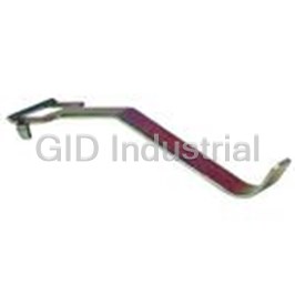
IDEC CORPORATION HS9Z-T1
Description
Key Wrench Included With Switch
HS9Z-T1
Part Number
HS9Z-T1
Price
Request Quote
Manufacturer
IDEC CORPORATION
Lead Time
Request Quote
Category
Tools and Supplies » Assembly Tools
Specifications
Manufacturer
IDEC Corporation
Manufacturers Part #
HS9Z-T1
Sub-Category
Electronics Assembly Tools
Factory Pack Quantity
1
Datasheet

Extracted Text
Overview XW Series E-Stops Interlock Switches Enabling Switches Safety Control Relays Light Curtains AS-Interface Safety at Work HS1E Solenoid Locking Safety Switches HS1E Full Size Solenoid Locking Switches Key features: • Plastic Housing: Lightweight • 1500N locking retention force • Available with a red or green indicator • Choose from 4 circuit configurations • Flexible Installation: The actuator can be accessed from two directions • Ease of Wiring: M3.5 termination screws Part Numbers (Mechanical Spring Lock Only) Actuator Keys & Accessories Contact Configuration LED Standard Manual Unlock Key Appearance Part Number Description 1 Straight Monitor Circuit None HS1E-40R HS1E-40KR HS9Z-A1 2 Actuator 3 Main Circuit Main circuit: 1NC + 1NC 4 Right-angle Green HS1E-44R-G HS1E-44KR-G HS9Z-A2 Monitor circuit: 1NO/1NO 5 Actuator Solenoid Power 6 Indicator Adjustable 7 Contacts are linked to Red HS1E-44R-R HS1E-44KR-R HS9Z-A3 Actuator the solenoid mechanically. 8 Key Wrench 1 HS9Z-T1 (included with Monitor Circuit None HS1E-140R HS1E-140KR 2 switch) 3 Conduit Main Circuit Main circuit: 1NC + 1NC 4 HS9Z-P1 Opening Plug Green HS1E-144R-G HS1E-144KR-G Monitor circuit: 1NO 5 (G1/2) Solenoid Power 6 Indicator 7 Red HS1E-144R-R HS1E-144KR-R Contacts are linked to 8 the solenoid mechanically. 1 None HS1E-240R HS1E-240KR Monitor Circuit 2 3 Main Circuit Main circuit: 1NC + 1NC 4 Green HS1E-244R-G HS1E-244KR-G + Monitor circuit: 1NC + 1NC 5 Solenoid Power 6 – Indicator 7 Contacts are linked to Red HS1E-244R-R HS1E-244KR-R the solenoid mechanically. 8 1 Monitor Circuit None HS1E-340R HS1E-340KR 2 3 Main Circuit 4 Main circuit: 1NC + 1NC Green HS1E-344R-G HS1E-344KR-G + Monitor circuit: 1NC 5 Solenoid Power 6 – Indicator 7 Contacts are linked to Red HS1E-344R-R HS1E-344KR-R the solenoid mechanically. 8 1. Key wrench for TORX screws (HS9Z-T1) is supplied with the interlock switch. 2. Actuator is not supplied with the interlock switch, and must be ordered separately. 3. TORX is a registered trademark of Camcar Textron. 800-262-IDEC (4332) • USA & Canada 315 HS1E Solenoid Locking Safety Switches Specifications EN1088, IEC60947-5-1, EN60947-5-1(TUV), ISO14119, GS-ET-19 (BG), UL508, CSA C22.2 No. 14, Conforming to Standards GB14048.5 (CCC approval), IEC60204-1, EN60204-1 (applicable standards for use) Operating Temperature –20 to +40˚C (no freezing) Storage Temperature –40 to +80˚C Relative Humidity 40 - 85% RH (no condensation) Altitude 2,000m maximum Rated Insulation Voltage (Ui) 300V (between LED or solenoid and ground: 60V) Impulse Withstand Voltage (Uimp) 4 kV (between LED or solenoid and ground: 2.5 kV) Between live and dead metal parts: 100 MΩ minimum Insulation Resistance Between live metal part and ground: 100 MΩ minimum (measured with 500V DC megger) Between live metal parts: 100 MΩ minimum Between terminals of the same pole: 100 MΩ minimum Electric Shock Protection Class II (according to IEC61140) Pollution Degree 3 (IEC60947-5-1) Degree of Protection IP67 (IEC60529) Operating Extremes 10 to 55 Hz, minimum (amplitude 0.35 mm) Vibration 2 Resistance Damage Limits 50 m/sec (approx. 5G) 2 Shock Resistance 1,000 m/sec (approx. 100G) Actuator Retention Force 1,500N minimum (per GS-ET-19) Actuator Operating Speed 0.05 to 1.0m/s Direct Opening Travel 11mm minimum Direct Opening Force 20N minimum Thermal Current (I ) Main circuit: 10A, Auxiliary circuit: 3A th Contact Gap Main circuit: 1.7 mm min., Auxiliary circuit: 1.2 mm min. Operating Frequency 900 operations/hour max. 1,000,000 operations min. (at full rated load) Mechanical Life 900 ops/hr (AC-12/250V, 6A) Electrical Life 100,000 operations (rated load) Conditional Short-circuit Current 100A (per IEC60947-5-1) Recommended Short Circuit Protection 250V, 10A fuse (Type D01 based on IEC60269-1, 60269-2) Operating Voltage 24V DC Current 292mA (initial value) Coil Resistance 102Ω (at 20ºC) Solenoid Pickup Voltage 20.4V maximum (at 20ºC) Unit Drop Out Voltage 2.4V minimum (at 20ºC) Allowable Voltage 26.4V max (continuous) Insulation Class Class F Operating Voltage 24V DC Current 10mA Indicator Light Source LED lamp Lens Color Red or Green Weight (approx.) 500g Contact Ratings Operating Voltage (Ue) 30V 125V 250V Resistive load (AC12) 10A 10A 6A AC Inductive load (AC15) 10A 5A 3A Resistive load (DC12) 6A – – DC Rated Operating Current (Ie) Inductive load (DC13) 3A 0.9A – Resistive load (AC12) – 3A 3A AC Inductive load (AC15) – – 3A Resistive load (DC12) 3A – – DC Inductive load (DC13) – 0.9A – www.IDEC.com 316 AS-Interface Safety at Work Light Curtains Safety Control Relays Enabling Switches Interlock Switches XW Series E-Stops Overview Auxiliary Main Circuit Circuit Overview XW Series E-Stops Interlock Switches Enabling Switches Safety Control Relays Light Curtains AS-Interface Safety at Work HS1E Solenoid Locking Safety Switches Application Examples and Circuit Diagrams HS1E-4 (Main Circuit: 1NC-1NC, Auxiliary Circuit: 1NO/1NO) Status 1 Status 2 Status 3 Status 4 Unlocked Manually Door Closed Door Closed Door Opened Door Opened Door Closed Switch/Door Machine ready to operate Machine cannot be started Machine cannot be started Machine cannot be started Machine cannot be started Status Solenoid de-energized Solenoid de-energized Solenoid energized Solenoid de-energized Solenoid de-energized Door Circuit Diagram Contacts are linked to Contacts are linked to Contacts are linked to Contacts are linked to Contacts are linked to Contacts are linked to Contacts are linked to Contacts are linked to Contacts are linked to Contacts are linked to Contacts are linked to Contacts are linked to Contacts are linked to Contacts are linked to Contacts are linked to Contacts are linked to Contacts are linked to Contacts are linked to Contacts are linked to Contacts are linked to Contacts are linked to Contacts are linked to Contacts are linked to Contacts are linked to Contacts are linked to the solenoid mechanically the solenoid mechanically the solenoid mechanically the solenoid mechanically the solenoid mechanically the solenoid mechanically the solenoid mechanically the solenoid mechanically the solenoid mechanically the solenoid mechanically the solenoid mechanically the solenoid mechanically the solenoid mechanically the solenoid mechanically the solenoid mechanically the solenoid mechanically the solenoid mechanically the solenoid mechanically the solenoid mechanically the solenoid mechanically the solenoid mechanically the solenoid mechanically the solenoid mechanically the solenoid mechanically the solenoid mechanically Main Circuit 3-4: Closed 3-4: Open 3-4: Open 3-4: Closed 3-4: Open Aux. Circuit 1-2: Open 1-2: Closed 1-2: Closed 1-2: Closed 1-2: Closed Solenoid 5-6: Power OFF 5-6: Power ON 5-6: Power ON 5-6: Power OFF 5-6: Power OFF HS1E-14 (Main Circuit: 1NC-1NC, Auxiliary Circuit: 1NO) Status 1 Status 2 Status 3 Status 4 Unlocked Manually Door Closed Door Closed Door Opened Door Opened Door Closed Switch/Door Machine ready to operate Machine cannot be started Machine cannot be started Machine cannot be started Machine cannot be started Status Solenoid de-energized Solenoid energized Solenoid energized Solenoid de-energized Solenoid de-energized Door (Note) (Note) (Note)(Note) (Note) Circuit Diagram Contacts are linked to Contacts are linked to Contacts are linked to Contacts are linked to Contacts are linked to Contacts are linked to Contacts are linked to Contacts are linked to Contacts are linked to Contacts are linked to Contacts are linked to Contacts are linked to Contacts are linked to Contacts are linked to Contacts are linked to Contacts are linked to Contacts are linked to Contacts are linked to Contacts are linked to Contacts are linked to Contacts are linked to Contacts are linked to Contacts are linked to Contacts are linked to Contacts are linked to the solenoid mechanically the solenoid mechanicallythe solenoid mechanically the solenoid mechanically the solenoid mechanically the solenoid mechanically the solenoid mechanically the solenoid mechanically the solenoid mechanically the solenoid mechanically the solenoid mechanically the solenoid mechanically the solenoid mechanically the solenoid mechanically the solenoid mechanically the solenoid mechanically the solenoid mechanically the solenoid mechanically the solenoid mechanicallythe solenoid mechanically the solenoid mechanically the solenoid mechanically the solenoid mechanically the solenoid mechanically the solenoid mechanically Main Circuit 3-4: Closed 3-4: Open 3-4: Open 3-4: Open 3-4: Open Aux. Circuit 1-2: Open 1-2: Open 1-2: Closed 1-2: Closed 1-2: Open Solenoid 5-6: Power OFF 5-6: Power ON 5-6: Power ON 5-6: Power OFF 5-6: Power OFF 1. Main Circuit: used to enable the machine to start only when the main circuit is closed. 2. Auxiliary Circuit: used to indicate whether the machine circuit or door is open or closed. 3. Terminals 7 and 8 are used for the LED indicator, and are isolated from solenoid and door status. 800-262-IDEC (4332) • USA & Canada 317 Solenoid Main Monitor Power Circuit Circuit Solenoid Main Monitor Solenoid Main Monitor Solenoid Main Monitor Power Circuit Circuit Power Circuit Circuit Solenoid Main Monitor Power Circuit Circuit Solenoid Main Monitor Power Circuit Circuit Solenoid Main Monitor Power Circuit Circuit Power Circuit Circuit Solenoid Main Monitor Solenoid Main Monitor Power Solenoid Circuit Main Monitor Circuit Power Circuit Circuit Power Circuit Circuit Solenoid Main Monitor Solenoid Main Monitor Power Circuit Circuit Main Solenoid Monitor Power Circuit Circuit Main Solenoid Monitor Solenoid Main Circuit Monitor Power Circuit Circuit Power Circuit Power Circuit Circuit Main Solenoid Main Solenoid Monitor Monitor Circuit Power Circuit Power Circuit Circuit Solenoid Main Monitor Main Solenoid Monitor Solenoid Main Power Circuit Circuit Monitor Circuit Power Circuit Power Circuit Circuit Solenoid Main Monitor Solenoid Main Monitor Power Circuit Circuit Solenoid Main Monitor Power Circuit Circuit Solenoid Main Monitor Solenoid Main Monitor Power Circuit Circuit Power Circuit Circuit Power Circuit Circuit Solenoid Main Monitor Solenoid Main Monitor Power Circuit Circuit Power Circuit Circuit Solenoid Main Monitor Solenoid Main Monitor Power Solenoid Circuit Main Circuit Monitor Power Circuit Circuit Power Circuit Circuit Solenoid Main Monitor Solenoid Main Monitor Power Circuit Circuit Solenoid Main Monitor Power Circuit Circuit Solenoid Main Monitor Main Solenoid Monitor Power Circuit Circuit Power Circuit Circuit Circuit Power Circuit Main Solenoid Main Monitor Solenoid Monitor Circuit Power Circuit Circuit Power Circuit Solenoid Main Monitor Solenoid Main Monitor Main Power Solenoid Circuit Circuit Monitor Power Circuit Circuit Circuit Power Circuit Main Solenoid Monitor Circuit Power Circuit Solenoid Main Monitor Solenoid Main Monitor Solenoid Main Monitor Power Circuit Circuit Power Circuit Circuit Solenoid Main Monitor Power Circuit Circuit Solenoid Main Monitor Power Circuit Circuit Solenoid Main Monitor Power Circuit Circuit Power Circuit Circuit Main Solenoid Monitor Solenoid Main Monitor Solenoid Circuit Main Monitor Power Circuit Power Circuit Circuit Power Circuit Circuit HS1E Solenoid Locking Safety Switches Application Examples and Circuit Diagrams, continued HS1E-24 (Main Circuit: 1NC+1NC, Auxiliary Circuit: 1NC+NC) Status 1 Status 2 Status 3 Status 4 Unlocked Manually Door Closed Door Closed Door Opened Door Opened Door Closed Switch/Door Machine ready to operate Machine cannot be started Machine cannot be started Machine cannot be started Machine cannot be started Status Solenoid de-energized Solenoid energized Solenoid energized Solenoid de-energized Solenoid de-energized Door 12 12 34 34 5 5 12 12 12 34 34 34 5 55 Circuit Diagram Contacts are linked to the Contacts are linked to the Contacts are linked to the Contacts are linked to the Contacts are linked to the Contacts are linked to the Contacts are linked to the Contacts are linked to the Contacts are linked to the Contacts are linked to the Contacts are linked to the Contacts are linked to the Contacts are linked to the Contacts are linked to the Contacts are linked to the Contacts are linked to the Contacts are linked to the Contacts are linked to the Contacts are linked to the Contacts are linked to the Contacts are linked to the Contacts are linked to the Contacts are linked to the Contacts are linked to the Contacts are linked to the solenoid mechanically solenoid mechanically solenoid mechanically solenoid mechanically solenoid mechanically solenoid mechanically solenoid mechanically solenoid mechanically solenoid mechanically solenoid mechanically solenoid mechanically solenoid mechanically solenoid mechanically solenoid mechanically solenoid mechanically solenoid mechanically solenoid mechanically solenoid mechanically solenoid mechanically solenoid mechanically solenoid mechanically solenoid mechanically solenoid mechanically solenoid mechanically solenoid mechanically Main Circuit 3-4: Closed 3-4: Open 3-4: Open 3-4: Open 3-4: Open Aux. Circuit 1-2: Closed 1-2: Open 1-2: Open 1-2: Open 1-2: Open Solenoid 5-6: Power OFF 5-6: Power ON 5-6: Power ON 5-6: Power OFF 5-6: Power OFF HS1E-34 (Main Circuit: 1NC+1NC, Auxiliary Circuit: 1NC) Status 1 Status 2 Status 3 Status 4 Unlocked Manually Door Closed Door Closed Door Opened Door Opened Door Closed Switch/Door Machine ready to operate Machine cannot be started Machine cannot be started Machine cannot be started Machine cannot be started Status Solenoid de-energized Solenoid energized Solenoid energized Solenoid de-energized Solenoid de-energized Door 12 34 5 12 12 34 34 5 5 12 12 34 34 5 5 (Note) (Note) (Note) (Note) (Note) Circuit Diagram Contacts are linked to the Contacts are linked to the Contacts are linked to the Contacts are linked to the Contacts are linked to the Contacts are linked to the Contacts are linked to the Contacts are linked to the Contacts are linked to the Contacts are linked to the Contacts are linked to the Contacts are linked to the Contacts are linked to the Contacts are linked to the Contacts are linked to the Contacts are linked to the Contacts are linked to the Contacts are linked to the Contacts are linked to the Contacts are linked to the Contacts are linked to the Contacts are linked to the Contacts are linked to the Contacts are linked to the Contacts are linked to the solenoid mechanically solenoid mechanically solenoid mechanically solenoid mechanically solenoid mechanically solenoid mechanically solenoid mechanically solenoid mechanically solenoid mechanically solenoid mechanically solenoid mechanically solenoid mechanically solenoid mechanically solenoid mechanically solenoid mechanically solenoid mechanically solenoid mechanically solenoid mechanically solenoid mechanically solenoid mechanically solenoid mechanically solenoid mechanically solenoid mechanically solenoid mechanically solenoid mechanically Main Circuit 3-4: Closed 3-4: Open 3-4: Open 3-4: Open 3-4: Open Aux. Circuit 1-2: Closed 1-2: Closed 1-2: Open 1-2: Open 1-2: Closed Solenoid 5-6: Power OFF 5-6: Power ON 5-6: Power ON 5-6: Power OFF 5-6: Power OFF 1. Main Circuit: used to enable the machine to start only when the main circuit is closed. 2. Auxiliary Circuit: used to indicate whether the machine circuit or door is open or closed. 3. Terminals 7 and 8 are used for the LED indicator, and are isolated from solenoid or door status. www.IDEC.com 318 AS-Interface Safety at Work Light Curtains Safety Control Relays Enabling Switches Interlock Switches XW Series E-Stops Overview Main Solenoid Monitor Circuit Power Circuit Solenoid Main Monitor Solenoid Solenoid Main Main Monitor Monitor Power Circuit Circuit Main Power Power Circuit Circuit Circuit Circuit Solenoid Monitor Solenoid Main Monitor Main Solenoid Monitor Circuit Power Circuit Power Circuit Circuit Circuit Power Circuit Solenoid Main Monitor Main Solenoid Monitor Power Circuit Circuit Circuit Main Power Solenoid Circuit Monitor Circuit Power Circuit Solenoid Main Monitor Power Circuit Circuit Solenoid Main Monitor Solenoid Solenoid Main Main Monitor Monitor Power Circuit Circuit Power Power Circuit Circuit Circuit Circuit Main Solenoid Monitor Solenoid Main Monitor Main Solenoid Monitor Circuit Power Circuit Power Circuit Circuit Circuit Power Circuit Solenoid Main Monitor Main Solenoid Monitor Power Circuit Circuit Circuit Main Power Solenoid Circuit Monitor Circuit Power Circuit Solenoid Main Monitor Power Circuit Circuit Solenoid Main Monitor Solenoid Solenoid Main Main Monitor Monitor Power Circuit Circuit Solenoid Main Monitor Power Power Circuit Circuit Circuit Circuit Solenoid Main Monitor Solenoid Main Monitor Power Circuit Circuit Power Circuit Circuit Power Circuit Circuit Solenoid Main Monitor Solenoid Main Monitor Power Circuit Circuit Power Solenoid Circuit Main Circuit Monitor Power Circuit Circuit Solenoid Main Monitor Power Circuit Circuit Solenoid Main Monitor Solenoid Solenoid Main Main Monitor Monitor Power Circuit Circuit Power Power Circuit Circuit Circuit Circuit Solenoid Main Monitor Solenoid Main Monitor Solenoid Main Monitor Power Circuit Circuit Power Circuit Circuit Power Circuit Circuit Solenoid Main Monitor Solenoid Main Monitor Power Circuit Circuit Power Solenoid Circuit Main Circuit Monitor Power Circuit Circuit Main Solenoid Monitor Circuit Power Circuit Solenoid Main Monitor Solenoid Solenoid Main Main Monitor Monitor Power Circuit Circuit Power Power Circuit Circuit Circuit Circuit Solenoid Main Monitor Solenoid Main Monitor Solenoid Main Monitor Power Circuit Circuit Power Circuit Circuit Solenoid Main Monitor Power Circuit Circuit Solenoid Main Monitor Power Circuit Circuit Power Solenoid Circuit Main Circuit Monitor Power Circuit Circuit Overview XW Series E-Stops Interlock Switches Enabling Switches Safety Control Relays Light Curtains AS-Interface Safety at Work 90° R3.2 HS1E Solenoid Locking Safety Switches Dimensions (mm) • HS1E- MS (Actuator Retention Force 1500N) HS1E with indicator - using 1500N operating force Vertical Mounting Horizontal Mounting 104 Right-angle Actuator HS9Z-A2 Straight Actuator HS9Z-A1 4 88 33 10 Actuator Cover 11.0 HS9Z-A2 Actuator ±1 ±1 6.5 22 17.5 Actuator Cover 54.3 (RP) 31.2 HS9Z-A1 Actuator 21 46.5 (RP) 2-M6 Actuator Mounting Holes 61 5 89 89 RP: Actuator Mounting Reference Position Slot Plug 3-M5 Screw (supplied) (Note) Mounting Hole Layout Note: Plug the unused actuator entry slot using the slot plug supplied with the interlock switch. • HS1E- MS (Actuator Retention Force 2000N) Accessories Vertical Mounting Horizontal Mounting Straight Actuator (mainly for sliding doors) HS9Z-A1 Right-angle Actuator (mainly for hinged doors) HS9Z-A2 104 Right-angle Actuator HS9Z-A2S Straight Actuator HS9Z-A1S 4 88 9 49.3 20 41.5 33 19.3 11.5 11 2-M6 1 7.4 1 Screws 2-M6 Screws 10 Actuator *After installing the actuator, 7.4 Actuator Cover Mounting Actuator (red) remove the actuator Actuator Cover Mounting Holes cover. (red) Holes Actuator Cover Actuator Cover 2 11.5 HS9Z-A2S Actuator ±0.5 HS9Z-A1S Actuator (3.5 ) ±0.5 17.5 19.2 Rubber Bushings 55.8 (RP) Rubber Bushings 22 2-M5 Actuator Mounting Holes 21 51.3 (RP) 61 5 89 RP: Actuator Mounting 89 Reference Position 36 Adjustable Actuator For HS1/HS2 Series (HS9Z-A3) 18 (Note) Slot Plug 3-M5 Screw • The (supplied) actuator angle is adjustable (0˚ to 20˚) for Actuator Stop (Note) Film (attached) hinged doors. Mounting Hole Layout • The minimum radius of the door opening can be as Note: Plug the unused actuator entry slot using the slot plug supplied with the interlock switch. small as 100mm. • Actuator Mounting Reference Position (RP) As shown in the figure below, the mounting reference position of the actuator when inserted in the interlock switch is: 2-M6 Screws The actuator cover touches the interlock switch lightly. 5 2 After mounting the actuator, remove the actuator cover from the actuator switch. 20 Door hinge Actuator Mounting Holes Angle Adjustment Screw (M3 hexagon socket head screw) Door Stop 30 Interlock Switch Interlock Switch Actuator Cover Actuator Cover Actuator All dimensions in mm. Actuator Door Stop 800-262-IDEC (4332) • USA & Canada 319 R3.2 R3.2 2 20° (8.0) ±1 8.5 ±0.5 7.0 70.3 (RP) 68.8 (RP) 45.4 45.4 40 51 39.2 40 49.5 39.2 1.5 35 35 49.5 10 5.5 2 10 5.5 4 2 4 7.5 7.5 4 4 22 40 2 22 12.3 23.5 26 5 12.3 23.5 26 5 45 121 45 121 129 63 129 63 4.1 29.2 43 33 max. 12 (21) 1 23.5 26 23.5 26 ±0.5 21 ±1 19.5 65.8 (RP) 61 (RP) 22 29.2 22 44 58 72 40 58 4.1 29.2 43 Minimum Radius 230 mm Minimum Radius 230 mm Minimum Radius 400 mmMinimum Radius 400 mm Minimum Radius 130 mm Minimum Radius 130 mm Minimum Radius 240 mm Minimum Radius 240 mm Minimum Radius 50 mm Minimum Radius 50 mm Minimum Radius 80 mm Minimum Radius 80 mm HS1E Solenoid Locking Safety Switches Accessories, continued Minimum Radius of Hinged Door • When using the interlock switch for a hinged door, refer to the minimum When using the HS9Z-A3 Angle Adjustable (vertical) Actuator radius of doors shown below. For the doors with small minimum radius, use • When the door hinge is on the extension line of the interlock switch surface: angle adjustable actuators (HS9ZA3 or HS9Z-A3S). Note: Because deviation or dislocation of hinged door may occur in actual applications, make sure of the correct operation before installation. HS9Z-A2 Actuator • When the door hinge is on the extension line of the interlock switch surface: • When the door hinge is on the extension line of the actuator mounting HS9Z-A3/A3S surface: Actuator Door Hinge HS9Z-A3/A3S Actuator Door Hinge • When the door hinge is on the extension line of the actuator mounting HS9Z-A2 surface: Actuator HS9Z-A2 Actuator Door Hinge Door Hinge www.IDEC.com 320 AS-Interface Safety at Work Light Curtains Safety Control Relays Enabling Switches Interlock Switches XW Series E-Stops Overview
Frequently asked questions
How does Electronics Finder differ from its competitors?

Is there a warranty for the HS9Z-T1?
Which carrier will Electronics Finder use to ship my parts?
Can I buy parts from Electronics Finder if I am outside the USA?
Which payment methods does Electronics Finder accept?
Why buy from GID?

Quality
We are industry veterans who take pride in our work

Protection
Avoid the dangers of risky trading in the gray market

Access
Our network of suppliers is ready and at your disposal

Savings
Maintain legacy systems to prevent costly downtime

Speed
Time is of the essence, and we are respectful of yours
Related Products
Removal Tool Uses With Terminal Block BND2
FL Athead Screwdriver 2.5mm FC9Z-SD2
Connecting Tool For Use With Safety Controller FS9Z-SD01
Locking Ring Wrench LW9Z-T1
Locking Ring Wrench MT-001
Locking Ring Wrench MT-002
Request a Quote

The quote request has been received
Close

Facing challenges or have inquiries? Feel free to contact us!
Call Us +1-469-283-2440
What they say about us
FANTASTIC RESOURCE
One of our top priorities is maintaining our business with precision, and we are constantly looking for affiliates that can help us achieve our goal. With the aid of GID Industrial, our obsolete product management has never been more efficient. They have been a great resource to our company, and have quickly become a go-to supplier on our list!
Bucher Emhart Glass
EXCELLENT SERVICE
With our strict fundamentals and high expectations, we were surprised when we came across GID Industrial and their competitive pricing. When we approached them with our issue, they were incredibly confident in being able to provide us with a seamless solution at the best price for us. GID Industrial quickly understood our needs and provided us with excellent service, as well as fully tested product to ensure what we received would be the right fit for our company.
Fuji
HARD TO FIND A BETTER PROVIDER
Our company provides services to aid in the manufacture of technological products, such as semiconductors and flat panel displays, and often searching for distributors of obsolete product we require can waste time and money. Finding GID Industrial proved to be a great asset to our company, with cost effective solutions and superior knowledge on all of their materials, it’d be hard to find a better provider of obsolete or hard to find products.
Applied Materials
CONSISTENTLY DELIVERS QUALITY SOLUTIONS
Over the years, the equipment used in our company becomes discontinued, but they’re still of great use to us and our customers. Once these products are no longer available through the manufacturer, finding a reliable, quick supplier is a necessity, and luckily for us, GID Industrial has provided the most trustworthy, quality solutions to our obsolete component needs.
Nidec Vamco
TERRIFIC RESOURCE
This company has been a terrific help to us (I work for Trican Well Service) in sourcing the Micron Ram Memory we needed for our Siemens computers. Great service! And great pricing! I know when the product is shipping and when it will arrive, all the way through the ordering process.
Trican Well Service
GO TO SOURCE
When I can't find an obsolete part, I first call GID and they'll come up with my parts every time. Great customer service and follow up as well. Scott emails me from time to time to touch base and see if we're having trouble finding something.....which is often with our 25 yr old equipment.
ConAgra Foods