

 Manufacturers
IDEC CORPORATION NC9Z-MA31
Description
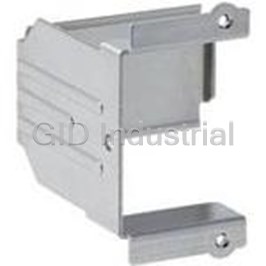
Panel Cut-out Mounting Bracket for 3-Pole Mode for Circuit Breaker
NC9Z-MA31
Part Number
NC9Z-MA31
Price
Request Quote
Manufacturer
IDEC CORPORATION
Lead Time
Request Quote
Category
Circuit Protection » Circuit Breaker Accessories
Specifications
Manufacturer
IDEC Corporation
Manufacturers Part #
NC9Z-MA31
Sub-Category
Circuit Breaker Accessories
Factory Pack Quantity
1
Datasheet

Extracted Text
IDEC Hydraulic-Magnetic Circuit Breakers NC1V Series Hydraulic-Magnetic Circuit Breakers Using a hydraulic-magnetic tripping method ensures calibration of the NC1V Circuit Breaker is unaffected by ambient temperature. The NC1V series will carry their full rated current continuously over a wide temperature range, from -10 to 60ºC, providing a more reliable and accurate system. With many other available features, make NC1V Circuit Breakers your choice to provide more value for your investment. Reliable, safe and accurate NC1V Circuit Breakers Hydraulic-magnetic tripping system • Slim housing design; 1, 2, and 3-pole • Cost-effective fuse block replacement - better • accuracy over temperature Flat retractable lever for safety operations • Spring-up terminals allow for use of ring terminals • DIN rail or direct panel mount • Optional built-in auxiliary or alarm controls • UL1077 • ON OFF Retractable Lever Auxiliary or Alarm Contact (Shown without terminal cover.) 2 3 NC1V Circuit Breakers Protection Specifications Part Numbers Operator Style Retractable lever Code Internal No. of Inertia Auxiliary Contact Part No. 6 Rated 8 Voltage Trip Coil Internal Circuit Series trip (current trip), Relay trip (voltage trip) Circuit Poles Delay Alarm Contact 7 Time Delay Curve Current Voltage Protection Method Hydraulic magnetic tripping system, Magnetic tripping system (voltage trip) 6 7 — NC1V-1100- No. of Poles 1-pole 2-pole 3-pole – One Auxiliary Contact NC1V-1111- 6 7 Note 1 Rated Voltage (AC/DC) 250V AC 50/60Hz, 65V DC 250V AC 50/60Hz, 125V DC 250V AC, 50/60Hz One Alarm Contact NC1V-1121 6 7 1-pole Rated Short-circuit 250V AC, 2500A 250V AC, 2500A 250V AC, 2500A — 6 7 NC1V-1100F- Capacity 65V DC, 2500A 125V DC, 2500A 6 7 Series Trip With One Auxiliary Contact NC1V-1111F- Rated Current 0.1A, 0.3A, 0.5A, 1A, 2A, 3A, 5A, 7A, 10A, 15A, 20A, 25A, 30A (Current Trip) One Alarm Contact NC1V-1121F- 6 7 Operation Characteristics Time delay curve curve M (slow), curve A (medium), S (instantaneous) , Curves M and A are also available with inertia delay option. Note 2 — NC1V-2100- 6 7 One Auxiliary Contact 6 7 NC1V-2111- Rated Current 30A Relay Trip Note 3 6 7 (Voltage Trip) Two Auxiliary Contacts NC1V-2112- Trip Voltage 24 to 48V DC (at 25°C), Voltage application duration 10 sec maximum, tripping time 0.1 sec maximum (at rated voltage) — One Alarm Contact NC1V-2121- 6 7 Contact Rating 125V AC 3A (resistive load), 30V DC 2A (resistive load) Auxiliary Contact/ One Auxiliary Contact and Alarm Contact 6 7 NC1V-2131- Minimum Applicable Load 24V DC 1mA (resistive load, reference value) One Alarm Contact 2-pole 6 7 — NC1V-2100F- Insulation Resistance 100MΩ minimum (500V DC megger) 0.1A One Auxiliary Contact NC1V-2111F- 6 7 2,000V AC, 1 minute (between terminals when main contacts are open, between live parts of different poles, between live and dead 0.3A Dielectric Strength parts) 0.5A Two Auxiliary Contacts NC1V-2112F- 6 7 With 600V AC (between terminals when auxiliary circuits are open) 1A One Alarm Contact 6 7 NC1V-2121F- 2A 2 2 Vibration Resistance Damage limits: 147m/s (10 to 55Hz) (1-pole, 2-pole), 78m/s (3-pole) 3A M (slow) 2 2 One Auxiliary Contact and (with rated current applied) Operating extremes: 98m/s (1-pole, 2-pole), 78m/s (3-pole) NC1V-2131F- 6 7 5A A (medium) — One Alarm Contact 2 2 7A S (instantaneous) Shock Resistance (S time delay curve: 80% rated Damage limits: 490m/s (1-pole, 2-pole), 297m/s (3-pole) — NC1V-3100- 6 7 2 10A current, A, M time delay curve: 100% rated current) Operating extremes: 196m/s (S, A, M types) One Auxiliary Contact 6 7 15A NC1V-3111- Electrical Life 10,000 cyles minimum (at rated curent), 10 operations per minute 20A 6 7 Two Auxiliary Contacts NC1V-3112- 25A Reference Temperature 40°C 30A Three Auxiliary Contacts NC1V-3113- 6 7 — −10 to +60°C (no freezing) Rated current is based on an ambient temperature of 40°C. When the operating temperature exceeds 40°C, One Alarm Contact NC1V-3121- 6 7 Operating Temperature derate the rated current by using the factors shown below. One Auxiliary Contact and 6 7 NC1V-3131- Operating Humidity 45 to 85% RH (no condensation) One Alarm Contact Two Auxiliary Contacts and Main Circuit Terminal Spring-up, fingersafe terminal: M4 screw (up to 20A), M5 screw (25A and 30A) NC1V-3132- 6 7 One Alarm Contact Terminal Style 3-pole Auxiliary/Alarm Contacts, 6 7 M3.5 screw — NC1V-3100F- Voltage Coil Terminal One Auxiliary Contact NC1V-3111F- 6 7 Weight (approx.) 1-pole: 90g, 2-pole: 170g, 3-pole: 260g Two Auxiliary Contacts NC1V-3112F- 6 7 1. 3-pole type is for AC voltage only. Three Auxiliary Contacts 6 7 NC1V-3113F- 2. For S (instantaneous) tripping curve, humming sound may occur when used in an AC sinusoidal-wave current circuit around 80% of the rated current, however, the Operating Temp. Derating Factor With performance of the circuit breaker will not be affected. 6 7 50°C 0.9 One Alarm Contact NC1V-3121F- To avoid unnecessary tripping, do not use in circuits where inrush currents may be present. 55°C 0.8 One Auxiliary Contact and 3. Relay trip (voltage trip) type is not equipped with an overcurrent trip function. 60°C 0.7 NC1V-3131F- 6 7 One Alarm Contact Do not use the NC1V circuit breakers in environments where they are exposed to extreme temperature, humidity, dust, corrosive gases, vibration, shock, or in a circuit where inrush current may be present, otherwise unnecessary operation and damage may occur. Two Auxiliary Contacts and 6 7 NC1V-3132F- One Alarm Contact 1-pole NC1V-1500- 8 Part Number Configuration 2-pole — — NC1V-2500- 8 — — DC24V 3-pole 8 NC1V-3500- NC1V - 2 1 00 F - 30A A DC24V Type Voltage Trip Coil Voltage 1 8 6 7 8 1. Specify rated current, time delay curve, or voltage trip coil voltage in place of when ordering. NC1V: Lever style DC24V: 24-48V DC 2. Inertia delay is for an AC circuit. Additionally, time delay curve of S (instantaneous) is not available with inertia delay. DIN rail and panel mounting -Specified for relay trip only. 3. 8 only applies to voltage trip models. No. of Poles 2 7 Time Delay Curve 1: 1-pole M: Slow 2: 2-pole A: Medium 3: 3-pole S: Instantaneous -For both AC/DC. Internal Circuit 3 -Specified for series trip only. 1: Series trip (current trip) 5: Relay trip (voltage trip) 6 Rated Current 0.1A, 0.3A, 0.5A, 1A, 2A, 3A, Auxiliary/Alarm Contacts 4 5A, 7A, 10A 15A, 20A, 25A, 30A 00: None -Specified for series trip only. 11: With one auxiliary contact 800.262.4332 Inertia Delay 5 12: With two auxiliary contacts Blank: Without 13: With three auxiliary contacts F: With 21: With one alarm contact www.IDEC.com/circuitbreaker -Inertia delay is for AC voltage only. 31: With one auxiliary contact and one alarm contact -Available with medium and slow types 32: With two auxiliary contacts and one alarm contact (not applicable with relay trip). 4 5 Relay Trip Series Trip (Voltage (Current Trip) Trip) NC1V Circuit Breakers Performance Internal Circuits Time Delay Curves at 40°C 1-pole 1000 NC1V-1100 NC1V-1111 NC1V-1121 NC1V-1500 1000 DC (Note) DC (Note) (Without auxiliary/alarm contacts) (With auxiliary contact) (With alarm contact) (Relay Trip) Curve A Curve M LINE LINE LINE One alarm contact. (medium) One auxiliary contact. (slow) AC AC A 100 100 10 10 B C 1 1 D C N N C N N 0.1 LOAD LOAD O C LOAD O C 0.1 0.01 0.01 2-pole NC1V-2100 NC1V-2111 NC1V-2121 NC1V-2500 (Without auxiliary/alarm contacts) (With auxiliary contact) (With alarm contact) (Relay Trip) 100 200 300 400 500 600 700 800 900 1000 100200 300400 500600 700800 9001000 One auxiliary contact. LINE LINE LINE LINE One alarm contact. LINE LINE Also available with two 125 Also available with 125 A A auxiliary contacts. one auxiliary contact Current (percent load of the rated current) Current (percent load of the rated current) and one alarm contact. B B 1000 C C Note: The entire shaded area applies to AC. Curve S For DC, the shaded area on the right of the dashed line applies. DC (Note) (instantaneous) 100 D D N N N N C C LOAD LOAD LOAD LOAD LOAD LOAD O C O C 10 3-pole 1 NC1V-3100 NC1V-3111 NC1V-3121 NC1V-3500 (Without auxiliary/alarm contacts) (With auxiliary contact) (With alarm contact) (Relay Trip) AC 800.262.4332 LINE LINE LINE LINE LINE LINE 0.1 LINE LINE LINE A A A www.IDEC.com/circuitbreaker 0.01 B B B C C C 100 200 300 400 500 600 700 800 900 1000 125 Current (percent load of the rated current) D D D N N N N C C LOAD LOAD LOAD O C LOAD LOAD LOAD O C LOAD LOAD LOAD One alarm contact. Also available with one One auxiliary contact. Also available with auxiliary and one alarm contacts, and two 1000 1000 two or three auxiliary contacts. Curve A Curve M auxiliary and one alarm contacts. (medium) (slow) With Inertia Delay With Inertia Delay 100 100 Overcurrent-Time Delay Characteristics (sec at 40°C) [vertical mounting] Percent of Rated Current 10 10 Item Time Delay Curve 100% 125% 150% 175% 200% 400% 600% 800% 1000% 1 1 *0.005 0.003 0.0027 0.002 0.002 0.002 0.002 S (instantaneous) NO TRIP — to 0.1 to 0.06 to 0.05 to 0.03 to 0.028 to 0.025 to 0.022 0.0055 0.004 0.004 0.1 0.1 A (medium) NO TRIP *25 to 240 16 to 140 — 6 to 32 0.4 to 4 to 1.5 to 0.8 to 0.65 0.006 0.004 0.004 M (slow) NO TRIP *60 to 600 30 to 200 — 9 to 60 0.4 to 10 0.01 to 4.5 to 1.8 to 0.8 0.01 With Inertia Delay 0.09 0.02 0.01 NO TRIP 25 to 240 — — 6 to 32 0.8 to 6 A (medium) to 3.5 to 1.8 to 1.0 100 200 300 400 500 600 700 800 900 1000 100 200 300 400 500 600 700 800 900 1000 With Inertia Delay 0.06 0.02 0.01 NO TRIP 60 to 600 — — 10 to 60 0.8 to 10 125 125 M (slow) to 4.5 to 3 to 1.75 Current (percent load of the rated current) Current (percent load of the rated current) *MAY TRIP on DC 6 7 AC (50/60Hz) AC (50/60Hz)/DC Time in sec Time in sec Time in sec Time in sec Time in sec 2-M4 2-M4 NC1V Circuit Breakers Reliability Time Delay Curve and Ambient Temperature Inertia Delay Dimensions (mm) 1-pole NC1V circuit breakers employ an electromagnetic tripping system, Inertia delay is designed not to trip on a non-repeating single where the rated current (trip current) is not affected by ambient pulse of 20 times the rated current (peak value) for a duration NC1V-1100 NC1V-1111 (Auxiliary Contact), NC1V-1121(Alarm Contact) DIN Rail (BNDN1000) DIN Rail (BNDN1000) temperatures. But, the time delay may vary with the oil viscosity in of 8ms. In addition, circuit breakers equipped with inertia delay M4 Terminal Screw M4 Terminal Screw 12.0 6.6 66.0 6.6 66.0 (up to 20A) 12.0 (up to 20A) the oil dash pot. Lower oil viscosity at higher temperatures results in a do not respond to high inrush currents caused by transformer or M5 Terminal Screw 48.3 48.3 M5 Terminal Screw (25A or more) (25A or more) shorter delay, whereas at lower temperatures, the delay will be longer. lamp loads, but perform the specified interruption on subsequent overcurrents. Inertia delay is available on AC circuits, and is not available with the series trip curve S (instantaneous). Temperature Correction Curve ON ON 12000 The time delay curves on the preceding page are measured at 1. Percent of rated current Pulse peak current 40°C. With reference to the following curves, time delays can be ×100 Protector rated current M3.5 Terminal Screw corrected according to ambient temperature. 2. Sinusoidal or parabolic pulse 2-ø4.5 Holes 2-ø4.5 Holes 10000 (for screw mounting) 5.0 (for screw mounting) 5.0 17.5 17.5 600 33.0 33.0 Terminal Cover Pulse peak current 500 400 8000 300 NC1V-1500 (Relay Trip) Mounting Hole Layout (M4 Mounting Screws) Pulse width (Duration) DIN Rail (BNDN1000) 12 200 12.0 6.6 66.0 48.3 6000 M5 Terminal Screw (30A) 100 80 60 4000 40 ON -20 -10 0 10 20 30 40 50 60 70 2000 Ambient Temperature (°C) M3.5 Terminal Screw 2-ø4.5 Holes The time delay is based on an ambient temperature of 40°C. Time de- (for screw mounting) 5.0 17.5 33.0 Terminal Cover lays at other temperatures are corrected according to the temperature 1 2 3 4 5 6 7 8 9 10 correction curve. The time delay of the instantaneous time delay curve Pulse Width (ms) (S) is not affected by the ambient temperature. 2 Pole When operating temperature exceeds Operating Temp. Derating Factor NC1V-2100 NC1V-2111 (one auxiliary contact), NC1V-2112 (two auxiliary contacts) DIN Rail (BNDN1000) 40°C, derate the rated current by NC1V-2121 (one alarm contact), NC1V-2131 (one auxiliary and one alarm contact) M4 Terminal Srew 50°C 0.9 29.5 6.6 66.0 (up to 20A) DIN Rail (BNDN1000) multiplying the derating factor shown M5 Terminal Screw 48.3 55°C 0.8 M4 Terminal Screw (25A or more) 29.5 6.6 66.0 (up to 20A) on the right. M5 Terminal Screw 48.3 60°C 0.7 (25A or more) ON Impedance and Coil Resistance ON Relay Trip (Voltage Trip) at 25°C Series Trip (Current Trip) at 25°C 2-ø4.5 Holes For DC For AC 50/60 Hz For DC M3.5 Terminal Screw (for screw mounting) Tripping Voltage 5.0 Rated Resistance (Ω) Impedance (Ω) Resistance (Ω) 35.0 2-ø4.5 Holes 33.0 Current (for screw mounting) 5.0 35.0 Curve S Curves A, M Curve S Curves A, M 33.0 Terminal Cover 24-48V 100.0 0.1A 66.0 116.0 43.0 106.0 Dimensions shown are for NC1V-2111 and NC1V-2121. Tolerance: ±25% 0.3A 6.6 11.0 4.1 10.0 0.5A 1.92 3.65 0.86 3.40 1A 0.50 0.93 0.25 0.90 NC1V-2500 (Relay Trip) Mounting Hole Layout (M4 Mounting Screws) DIN Rail (BNDN1000) 29.5 2A 0.16 0.27 0.11 0.25 29.5 6.6 66.0 3A 0.07 0.12 0.050 0.11 48.3 M5 Terminal Screws (30A) 5A 0.025 0.050 0.015 0.045 Voltage Drop Due to Coil Resistance or Impedance 7A 0.014 0.027 0.011 0.025 10A 0.007 0.021 0.005 0.020 The internal resistance or impedance of a circuit breaker tends to be 15A 0.006 0.010 0.005 0.009 larger for a smaller-rated current. Therefore, when circuit breakers ON 20A 0.005 0.006 0.004 0.005 with a small rated current are used, voltage drop should be taken 25A 0.004 0.005 0.004 0.005 30A 0.003 0.004 0.003 0.004 into consideration. Internal resistance also varies with time delay 800.262.4332 M3.5 Terminal Screw 2-ø4.5 Holes Tolerance: ±25% (up to 20A), curves, which should also be considered during installation. (for screw mounting) 5.0 ±50% (25A and 30A) 35.0 33.0 Terminal Cover www.IDEC.com/circuitbreaker 8 9 Change of Time Delay (%) Percent of Rated Current (%) 71.4 71.4 71.4 71.4 56.0 56.0 56.0 56.0 72.5 72.5 72.5 72.5 44.0 48.4 48.4 44.0 78.8 78.8 78.8 78.8 71.4 71.4 56.0 56.0 71.4 71.4 72.5 72.5 48.4 48.4 78.8 78.8 LINE LOAD 2-M4 NC1V Circuit Breakers Safety 3-pole Applicable Wire and Crimp Terminals Product Markings (Example: NC1V-1111-30AA) Connectable Applicable Tightening NC1V-3100 NC1V-3111 (one auxiliary contact), NC1V-3112 (two auxiliary contacts) Terminal Terminal Screw Wire Size Crimping Torque DIN Rail (BNDN1000) 2 NC1V-3113 (three auxiliary contacts), NC1V-3121 (one alarm Contact) (mm ) Terminal (N·m) M4 Terminal Screw PSE Certification 47.0 6.6 66.0 (up to 20A) NC1V-3131 (one auxiliary and one alarm contact) 48.3 Spring-up, fingersafe, M5 Terminal Srew 0.25 to 1.65 R1.25-4 Part No. NC1V-3132 (two auxiliary and one alarm contacts) (25A or more) PS slotted Phillips screw with E J E T No. of Poles Rated Voltage DIN Rail (BNDN1000) 220VAC 30A I.C.2500A 1.04 to 2.63 R2-4 1 to 1.4 M4 Terminal Screw square washer CIRCUIT PROTECTOR Time Delay Curve Rated Current 47.0 (up to 20A) 6.6 66.0 NC1V-1111 POLE 1 2.63 to 6.64 R5.5-4 (up to 20A) Ue 250VAC 50/60Hz · 65VDC M5 Terminal Srew Auxiliary/Alarm Contact Rating 48.3 In 30A CURVE A (25A or more) Suppl. Prot. 0.25 to 1.65 R1.25-5 AUX. SW Reference Operating Spring-up fingersafe 125VAC 3A Temperature 30 VDC 2A terminal 1.04 to 2.63 R2-5 1.8 to 2.2 A.T. 40°C ON JAPAN (25A and 30A) 2.63 to 6.64 R5.5-5 Certification Marks ON 0.25 to 1.65 R1.25-3.5 2-ø4.5 Holes (for screw mounting) 5.0 Slotted Phillips screw with 52.5 0.7 to 0.9 33.0 square washer M3.5 Terminal Srew 1.04 to 2.63 R2-3.5 2-ø4.5 Holes Installation of Auxiliary/Alarm Terminal Cover (for screw mounting) 5.0 52.5 33.0 Terminal Cover After wiring the terminals, install the terminal cover by aligning with the For wiring the main circuit terminal, use the applicable crimp terminals • circuit breaker as shown below. Dimensions shown are for NC1V-3111 and NC1V-3121. and tighten to the recommended torque. When using the NC1V circuit breaker as CSA-certified product, use with • NC1V-3500 (Relay Trip) Mounting Hole Layout (M4 Mounting Screws) CSA-certified crimp terminal. DIN Rail (BNDN1000) 47.0 47.0 6.6 66.0 When using the NC1V circuit breaker as UL-listed product, use with • 48.3 UL-listed crimp terminal. M5 Terminal Screw (30A) Terminal cover installed Panel Mounting Screws (not supplied) Srew Type Tightening Torque Shape ON Spring Washer M4 0.8 to 1.0 N·m Plain Washer M3.5 Terminal Screw 2-ø4.5 Holes (for screw mounting) 5.0 52.5 33.0 Terminal Cover Accessories Item Part No. Description Item Part No. Description Instructions Installation Angle DIN Rail Installation Panel Cut-Out Tripping method is hydraulic magnetic. Minimum operating current Fasten the DIN rail securely. NC9Z-MA11 Mounting bracket for 1. 1-pole model varies with installation angle. Operating currents are influenced by the With the latch facing downward, install the NC1V circuit breaker on 2. Padlock weight of movable iron core. With reference to the following figures, the DIN rail as shown below. NC9Z-LK1 attachment correct the rated current. DIN Rail Removal Using a flat screwdriver, pull the latch on the circuit breaker to remove from the DIN rail. Panel Cut-Out NC9Z-MA21 Mounting bracket for 100% 2-pole model Installing Removing 35mm-wide 35mm-wide DIN Rail DIN Rail Push Flat Panel Cut-Out Srcrewdriver NC9Z-MA31 Mounting bracket for 3-pole model Replacement Wiring Latch NC9Z-TA1 Clip when using panel mount brackets 120% 90% Marking Plate NC9Z-PW1 Holder* 100% 800.262.4332 *Marking plate not supplied. Minimum operating current is calculated from the following formula: Auxiliary/Alarm (Minimum operating current) = (Rated current) × (Correction factor by www.IDEC.com/circuitbreaker NC1V-AUX-CV Terminal Cover (Nylon installation angle) × (Reference minimum tripping current rate) - PA66) 10 11 71.4 71.4 56.0 56.0 72.5 72.5 48.4 44.0 78.8 78.8 71.4 56.0 71.4 72.5 48.4 78.8 Auxiliary Contact Alarm Contact Main Circuit Terminals Voltage Coil Terminals PS6R: World's First Expandable Power Supply Less cost + less space = more savings! More value! Replace 3 full-priced, space-consuming power supplies with 1. Reduce the amount of space needed for wiring and installation The addition of a DC-DC converter expansion module will eliminate the need for multiple power supplies or snap on a branch terminal module to replace multiple terminal blocks. Technical support: Flexibility, expandability, versatility support@idec.com Add DC-DC converter units for up to three separate output voltages (5, 12, or 15V). Or, add a branch terminal module to get two additional + and – slots. Sales support: sales@idec.com Energy-saving 93% Efficiency Save energy and generate less heat in the cabinet, reducing temperature stress on critical components. 800.262.4332 Easy Maintenance - LED Indicator DC low or ON indicator. www.IDEC.com/usa FSC Placement Think Automation and beyond... www.IDEC.com USA Japan China Hong Kong Taiwan IDEC Corporation IDEC Corporation IDEC (Beijing) Corporation IDEC (H.K.) Co., Ltd. IDEC Taiwan Corporation Tel: (408) 747-0550 Tel: +81-6-6398-2527 Tel: +86-10-6581-6131 Tel: +852-2803-8989 Tel: +886-2-2698-3929 opencontact@IDEC.com marketing@IDEC.co.jp info@hk.IDEC.com service@tw.IDEC.com IDEC (Shanghai) Corporation Canada Germany Tel: +86-21-6135-1515 Singapore Thailand IDEC Canada Ltd. IDEC Elektrotechnik GmbH idec@cn.IDEC.com IDEC Asia Pte. Ltd. IDEC Asia (Thailand) Co., Ltd. Tel: (905) 890-8561 Tel: +49-40-253054-0 Tel: +65-6746-1155 Tel: +662-392-9765 IDEC (Shenzhen) Corporation sales@ca.IDEC.com service@IDEC.de info@sg.IDEC.com sales@th.IDEC.com Tel: +86-755-8356-2977 Australia United Kingdom IDEC Australia Pty. Ltd. IDEC Electronics Ltd. Tel: +61-3-8523-5900 Tel: +44-1256-321000 ©2014 IDEC Corporation. All Rights Reserved. sales@au.IDEC.com sales@uk.IDEC.com Catalog No. NC9Y-B100-2 08/14 5K Specifications and other descriptions in this catalog are subject to change without notice.
Frequently asked questions
How does Electronics Finder differ from its competitors?

Is there a warranty for the NC9Z-MA31?
Which carrier will Electronics Finder use to ship my parts?
Can I buy parts from Electronics Finder if I am outside the USA?
Which payment methods does Electronics Finder accept?
Why buy from GID?

Quality
We are industry veterans who take pride in our work

Protection
Avoid the dangers of risky trading in the gray market

Access
Our network of suppliers is ready and at your disposal

Savings
Maintain legacy systems to prevent costly downtime

Speed
Time is of the essence, and we are respectful of yours
Related Products

Padlock Attachment for Circuit Breaker NC9Z-LK1

Panel Cut-out Mounting Bracket for 1-Pole Mode for Circuit Breaker NC9Z-MA11

Panel Cut-out Mounting Bracket for 2-Pole Mode for Circuit Breaker NC9Z-MA21

Marking Plate Holder for Circuit Breaker NC9Z-PW1
Replacement Wiring Clip When Using Panel Mount Brackets for Circuit Breaker NC9Z-TA1
Color Caps For Circuit Breaker NR21
Request a Quote

The quote request has been received
Close

Facing challenges or have inquiries? Feel free to contact us!
Call Us +1-469-283-2440
What they say about us
FANTASTIC RESOURCE
One of our top priorities is maintaining our business with precision, and we are constantly looking for affiliates that can help us achieve our goal. With the aid of GID Industrial, our obsolete product management has never been more efficient. They have been a great resource to our company, and have quickly become a go-to supplier on our list!
Bucher Emhart Glass
EXCELLENT SERVICE
With our strict fundamentals and high expectations, we were surprised when we came across GID Industrial and their competitive pricing. When we approached them with our issue, they were incredibly confident in being able to provide us with a seamless solution at the best price for us. GID Industrial quickly understood our needs and provided us with excellent service, as well as fully tested product to ensure what we received would be the right fit for our company.
Fuji
HARD TO FIND A BETTER PROVIDER
Our company provides services to aid in the manufacture of technological products, such as semiconductors and flat panel displays, and often searching for distributors of obsolete product we require can waste time and money. Finding GID Industrial proved to be a great asset to our company, with cost effective solutions and superior knowledge on all of their materials, it’d be hard to find a better provider of obsolete or hard to find products.
Applied Materials
CONSISTENTLY DELIVERS QUALITY SOLUTIONS
Over the years, the equipment used in our company becomes discontinued, but they’re still of great use to us and our customers. Once these products are no longer available through the manufacturer, finding a reliable, quick supplier is a necessity, and luckily for us, GID Industrial has provided the most trustworthy, quality solutions to our obsolete component needs.
Nidec Vamco
TERRIFIC RESOURCE
This company has been a terrific help to us (I work for Trican Well Service) in sourcing the Micron Ram Memory we needed for our Siemens computers. Great service! And great pricing! I know when the product is shipping and when it will arrive, all the way through the ordering process.
Trican Well Service
GO TO SOURCE
When I can't find an obsolete part, I first call GID and they'll come up with my parts every time. Great customer service and follow up as well. Scott emails me from time to time to touch base and see if we're having trouble finding something.....which is often with our 25 yr old equipment.
ConAgra Foods