

 Manufacturers
IDEC CORPORATION TWR-526
Description
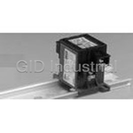
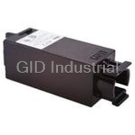
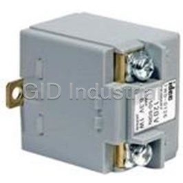
Power Transformer 1W DIN Rail
TWR-526
Part Number
TWR-526
Price
Request Quote
Manufacturer
IDEC CORPORATION
Lead Time
Request Quote
Category
Magnetics » Power Transformer
Specifications
Manufacturer
IDEC Corporation
Manufacturers Part #
TWR-526
Industry Aliases
TWR526
Sub-Category
Magnetic Power Transformers
Factory Pack Quantity
1
Datasheet

Extracted Text
Think Automation and beyond... Flush Silhouette LW Series Control Units L6/A6 Series Accessories Add Style to Your Panel LW Series Flush Silhouette Control Units Bezel Panel Lens Pilot Illuminated Shape Pushbutton Cut-out Type Light Pushbutton Size Material ˙ Flush ş28 Metal ş25.3 Extended Flush ş28 Plastic ş25.3 Extended ˙ Flush �28 Plastic �24.5 Extended Slimmer than Ever 2 mm (Metal) (Plastic) L6/A6 Series Flush Silhouette Bezels Bezel Panel Pilot Illuminated Key Illuminated Shape Series Pushbutton Selector Others Cut-out Light Pushbutton Selector Selector Size Material ˙ L6 (Separate Type) ş24 Metal ş20.2 (Lever) A6 (Unibody Type) L6 (Separate Type) ş24 Plastic ş20.2 (Lever) A6 (Unibody Type) L6 (Separate Type) �24 Plastic �20.2 A6 (Unibody Type) L6 24 20.2 (Separate Type) Plastic × × (Buzzer) A6 30 26.2 (Unibody Type) Note: For the L6 and A6 series, ţush silhouette bezels are ordered separately to be combined with control units. Flush Silhouette LW Series Control Units Flush bezel projects only 2 mm from front of panel ø28 round and 28-mm square black plastic bezels. Round metallic bezels are also available. • ş25.3-mm round panel cut-out, 24.5-mm square panel cut-out. • Collective mounting is possible. • Separate type control units with a locking lever enable easy installation even when mounted collectively. • Gold (gold-clad silver) or silver contacts. • Degree of protection: IP65 (IEC 60529) • UL recognized and CSA certified. EN compliant. Safety Standards File No. or Organization UL Recognition UL File No. E55996 CSA 166730 (LR21451) TÜV Rheinland EN60947-1 EN EN60947-5-1 EC Low Voltage Directive SpeciŢcations and Ratings Contact Ratings SpeciŢcations • Gold Contact –25 to +60°C (no freezing) Operating Temperature Illuminated units: –25 to +50°C Maximum Voltage 250V AC/DC Storage Temperature –40 to +80° Thermal Current 3A Operating Humidity 45 to 85% RH (no condensation) Operating Voltage 30V DC 125V AC Contact Resistance 50 mΩ maximum (initial value) Operating Current 0.1A 0.1A Insulation Resistance 100 MΩ minimum (500V DC megger) (resistive load) Between live part and ground: Contact Material Gold-clad silver 2,500V AC, 1 minute Between terminals of different poles: Minimum applicable load (reference value): 5V AC/DC, 1mA Switch Unit 2,500V AC, 1 minute Dielectric (Applicable range is subject to the operating condition and load.) Between terminals of the same poles: Strength 1,000V AC, 1 minute • Silver Contact Illumination Between live part and ground: Operating Voltage 30V 125V 250V Unit 2,500V AC, 1 minute Resistive Load – 3A 2A AC Operating extremes: Vibration Resistance 50/60Hz Inductive Load – 2A 1.5A Operating 5 to 55 Hz, amplitude 0.5 mm 2 Current Resistive Load 2A 0.4A – Damage limits: 1,000 m/s Shock Resistance DC 2 Operating extremes: 100 m/s Inductive Load 1A 0.2A – Mechanical Life Momentary: 1,000,000 Thermal Current 5A (minimum operations) Maintained: 500,000 Contact Material Silver Momentary: 100,000 (∗1 ) Electrical Life Maintained: 100,000 (∗2 ) AC inductive load: PF = 0.6 to 0.7 (minimum operations) ∗1 Switching frequency 1,800 operations/h DC inductive load: L/R = 7 msec max. ∗2 Switching frequency 900 operations/h Degree of Protection IP65 (IEC 60529) Solder/tab terminal no. 110 Terminal Style PC board terminal Screw terminal 4 Flush Silhouette LW Series Control Units LED Lamp Ratings (LSTD Type) Type No. LSTD-6➁ LSTD-1➁ LSTD-2➁ Lamp Base BA9S/13 Rated Voltage 6V AC/DC 12V AC/DC 24V AC/DC Voltage Range 6V AC/DC ±10% 12V AC/DC ±10% 24V AC/DC ±10% A, R, W, Y: 17 mA AC 11 mA 11 mA G, S: 8 mA Current Draw A, R, W, Y: 14 mA DC 10 mA 10 mA G, S: 5.5 mA Color Code ➁ A (amber), G (green), R (red), S (blue), W (white), Y (yellow) Lamp Base Color Same as illumination color Voltage Marking Die stamped on the base Life (reference value) Approx. 50,000 hours (The luminance is reduced to 50% the initial intensity when used on complete DC.) A, R, W, Y Internal Circuit G, S LED Chip Protection Diode Zener Diode Mounting Hole Layout Ordering Information • Round Type Standard Units +0.2 ş25.3 -0.1 • Specify a button or lens color code in the Type No. • All illuminated units are supplied with an LED lamp. • All standard units are UL recognized, CSA certiŢed, and EN compliant (TÜV Rheinland). 28∗ • Square Type +0.2 24.5 -0.1 28∗ Note: Mounting centers should be determined to ensure easy operation. ∗ Screw terminal type: Vertical 40 mm, Horizontal 26 mm minimum 5 28∗ 28∗ LOCK TOP LOCK LOCK LOCK Flush Silhouette LW Series Pushbuttons Flush Bezel (Round Metal Bezel) – Non-Illuminated Type No. Operation Contact ➀ Button Color Shape Contact Solder/Tab PC Board Type Material Code Screw Terminal Terminal Terminal Round Flush SPDT LW6MB-M1C1➀ LW6MB-M1C1V➀ – with Metal Bezel Gold DPDT LW6MB-M1C2➀ LW6MB-M1C2V➀ LW6MB-M1C2M➀ LW6MB-M1 3PDT LW6MB-M1C3➀ LW6MB-M1C3V➀ – Momentary LW6MB-A1 SPDT LW6MB-M1C5➀ –– Silver DPDT LW6MB-M1C6➀ – LW6MB-M1C6M➀ 3PDT LW6MB-M1C7➀ –– SPDT LW6MB-A1C1➀ LW6MB-A1C1V➀ – Gold DPDT LW6MB-A1C2➀ LW6MB-A1C2V➀ LW6MB-A1C2M➀ Specify a button color code in 3PDT LW6MB-A1C3➀ LW6MB-A1C3V➀ – Maintained place of ➀ in the SPDT LW6MB-A1C5➀ –– Type No. Silver DPDT LW6MB-A1C6➀ – LW6MB-A1C6M➀ 3PDT LW6MB-A1C7➀ –– LA: amber LB: black Round Extended SPDT LW6MB-M2C1➀ LW6MB-M2C1V➀ – LG: green with Metal Bezel Gold DPDT LW6MB-M2C2➀ LW6MB-M2C2V➀ LW6MB-M2C2M➀ LR: red LW6MB-M2 3PDT LW6MB-M2C3➀ LW6MB-M2C3V➀ – LS: blue Momentary LW6MB-A2 SPDT LW6MB-M2C5➀ –– LW: white LY: yellow Silver DPDT LW6MB-M2C6➀ – LW6MB-M2C6M➀ 3PDT LW6MB-M2C7➀ –– SPDT LW6MB-A2C1➀ LW6MB-A2C1V➀ – Gold DPDT LW6MB-A2C2➀ LW6MB-A2C2V➀ LW6MB-A2C2M➀ 3PDT LW6MB-A2C3➀ LW6MB-A2C3V➀ – Maintained SPDT LW6MB-A2C5➀ –– Silver DPDT LW6MB-A2C6➀ – LW6MB-A2C6M➀ 3PDT LW6MB-A2C7➀ –– • Lenses for illuminated pushbuttons are used for ţush silhouette pushbuttons. Dimensions Panel Thickness All dimensions in mm. 0.8 to 3.2 M3 Terminal Screw Terminal Cover Mounting Bracket LW-VL2 Terminal Cover 1.0 2.6 Locking Ring LW-VL2M 2-R0.6 ∗Tab Terminal Rubber Washer 61.9 54 PC Board Terminal Tab Terminal 0.8W × 0.5t 2.8W × 0.5t Round Square Flush 8.5 18.7 28 ∗ 60.5 5.4 43 9 43 2 PC Board Terminal Solder/Tab Terminal Screw Terminal Terminal Arrangement (Bottom View) Extended TOP 3 2 1 2.0 5.6 Bottom View Note: SPDT has C, NO, and NC only in the center. DPDT has C, NO, and NC 25 25 25.4 only on the right and left. 26.5 Screw terminal type has only DPDT. Screw Terminal PC Board Terminal Solder/Tab Terminal • For PC board dimensions, see page 7. 6 ş28 R18 R18 R18 23.2 8.2 2.0 6.2 16.2 5 5 X2 X1 6.8 6.8 X2 1.2 4.85 C NO NC C NO NC 18.2 16.2 6 6 6.8 6.8 1.2 4.85 1.2 CNO NC CNO NC CNO NC +0.1 9-ş1.2 0 Flush Silhouette LW Series Pushbuttons Flush Bezel (Round / Square Black Plastic Bezel) – Non-Illuminated Type No. Operation Contact ➀ Button Color Shape Contact Solder/Tab PC Board Type Material Code Screw Terminal Terminal Terminal Round Flush SPDT LW6B-M1C1➀ LW6B-M1C1V➀ – with Black Plastic Bezel Gold DPDT LW6B-M1C2➀ LW6B-M1C2V➀ LW6B-M1C2M➀ LW6B-M1 3PDT LW6B-M1C3➀ LW6B-M1C3V➀ – Momentary LW6B-A1 SPDT LW6B-M1C5➀ –– Silver DPDT LW6B-M1C6➀ – LW6B-M1C6M➀ 3PDT LW6B-M1C7➀ –– SPDT LW6B-A1C1➀ LW6B-A1C1V➀ – Gold DPDT LW6B-A1C2➀ LW6B-A1C2V➀ LW6B-A1C2M➀ 3PDT LW6B-A1C3➀ LW6B-A1C3V➀ – Maintained SPDT LW6B-A1C5➀ –– Silver DPDT LW6B-A1C6➀ – LW6B-A1C6M➀ 3PDT LW6B-A1C7➀ –– Round Extended SPDT LW6B-M2C1➀ LW6B-M2C1V➀ – with Black Plastic Bezel Gold DPDT LW6B-M2C2➀ LW6B-M2C2V➀ LW6B-M2C2M➀ Specify a button LW6B-M2 color code in 3PDT LW6B-M2C3➀ LW6B-M2C3V➀ – Momentary LW6B-A2 place of ➀ in the SPDT LW6B-M2C5➀ –– Type No. Silver DPDT LW6B-M2C6➀ – LW6B-M2C6M➀ 3PDT LW6B-M2C7➀ –– LA: amber LB: black SPDT LW6B-A2C1➀ LW6B-A2C1V➀ – LG: green Gold DPDT LW6B-A2C2➀ LW6B-A2C2V➀ LW6B-A2C2M➀ LR: red 3PDT LW6B-A2C3➀ LW6B-A2C3V➀ – LS: blue Maintained SPDT LW6B-A2C5➀ –– LW: white LY: yellow Silver DPDT LW6B-A2C6➀ – LW6B-A2C6M➀ 3PDT LW6B-A2C7➀ –– Square Flush SPDT LW7B-M1C1➀ LW7B-M1C1V➀ – with Black Plastic Bezel Gold DPDT LW7B-M1C2➀ LW7B-M1C2V➀ LW7B-M1C2M➀ LW7B-M1 3PDT LW7B-M1C3➀ LW7B-M1C3V➀ – Momentary LW7B-A1 SPDT LW7B-M1C5➀ –– Silver DPDT LW7B-M1C6➀ – LW7B-M1C6M➀ 3PDT LW7B-M1C7➀ –– SPDT LW7B-A1C1➀ LW7B-A1C1V➀ – Gold DPDT LW7B-A1C2➀ LW7B-A1C2V➀ LW7B-A1C2M➀ 3PDT LW7B-A1C3➀ LW7B-A1C3V➀ – Maintained SPDT LW7B-A1C5➀ –– Silver DPDT LW7B-A1C6➀ – LW7B-A1C6M➀ 3PDT LW7B-A1C7➀ –– • Lenses for illuminated pushbuttons are used for ţush silhouette pushbuttons. For dimensions, see page 6. PC Board Drilling Layout (Bottom View) ±0.05 6.8 ±0.05 1.6 (PC Board) 6.8 4.85 (0.5) (0.5) (0.5) NC Terminal NO Terminal COM Terminal Switch Switch Switch Terminal Terminal Terminal Soldered 3C 2C 1C Mounting All dimensions in mm. Side Side Pay attention to the pattern of the PC board as the terminals on the mounting surface are 2.8 mm wide. 7 (0.8) (0.8) (0.8) 2.4 5 5 2.4 2.8 2.8 2.8 Flush Silhouette LW Series Pilot Lights Flush Bezel (Round Metal / Plastic and Square Black Plastic Bezel) – LED Illuminated Type No ➁ Lens Color Solder/Tab PC Board Shape Lamp Input Type Screw Terminal Code Terminal Terminal (Unibody Type) (Unibody Type) (Separate Type) Round Flush with Metal Bezel 6V AC/DC ±10% LW6MP-12➁ LW6MP-1C02V➁ LW6MP-12M➁ LW6MP-1 LED 12V AC/DC ±10% LW6MP-13➁ LW6MP-1C03V➁ LW6MP-13M➁ 24V AC/DC ±10% LW6MP-14➁ LW6MP-1C04V➁ LW6MP-14M➁ Round Extended with Metal Bezel 6V AC/DC ±10% LW6MP-22➁ LW6MP-2C02V➁ LW6MP-22M➁ LW6MP-2 LED 12V AC/DC ±10% LW6MP-23➁ LW6MP-2C03V➁ LW6MP-23M➁ 24V AC/DC ±10% LW6MP-24➁ LW6MP-2C04V➁ LW6MP-24M➁ Round Flush with Black Plastic Bezel 6V AC/DC ±10% LW6P-12➁ LW6P-1C02V➁ LW6P-12M➁ LW6P-1 LED 12V AC/DC ±10% LW6P-13➁ LW6P-1C03V➁ LW6P-13M➁ Specify a lens color code in place of ➁ in the 24V AC/DC ±10% LW6P-14➁ LW6P-1C04V➁ LW6P-14M➁ Type No. A: amber Round Extended G: green with Black Plastic Bezel 6V AC/DC ±10% LW6P-22➁ LW6P-2C02V➁ LW6P-22M➁ R: red LW6P-2 S: blue W: white Y: yellow LED 12V AC/DC ±10% LW6P-23➁ LW6P-2C03V➁ LW6P-23M➁ 24V AC/DC ±10% LW6P-24➁ LW6P-2C04V➁ LW6P-24M➁ Square Flush with Black Plastic Bezel 6V AC/DC ±10% LW7P-12➁ LW7P-1C02V➁ LW7P-12M➁ LW7P-1 LED 12V AC/DC ±10% LW7P-13➁ LW7P-1C03V➁ LW7P-13M➁ 24V AC/DC ±10% LW7P-14➁ LW7P-1C04V➁ LW7P-14M➁ Square Extended with Black Plastic Bezel 6V AC/DC ±10% LW7P-22➁ LW7P-2C02V➁ LW7P-22M➁ LW7P-2 LED 12V AC/DC ±10% LW7P-23➁ LW7P-2C03V➁ LW7P-23M➁ 24V AC/DC ±10% LW7P-24➁ LW7P-2C04V➁ LW7P-24M➁ • Every pilot light contains an LED lamp (LSTD) of the speciŢed color and voltage. 8 LOCK TOP +0.1 3-ş1.2 0 Flush Silhouette LW Series Pilot Lights Dimensions • Unibody Type • Separate Type Rubber Washer Mounting Bracket Mounting Bracket Panel Thickness Locking Ring Panel Thickness 0.8 to 3.2 Locking Ring 0.8 to 3.2 M3 Terminal Screw Terminal Cover Terminal Cover LW-PVL LW-PVLM 43 ∗ 41.8 Rubber Washer Tab Terminal PC Board Terminal 2.8W × 0.5t 7.2 0.8W × 0.5t Flush Flush ∗ 2 8.5 18.7 2 26 7.7 33.3 5.5 2 4 7.5 34 2 43 Screw Terminal Solder/Tab Terminal PC Board Terminal Round (Extended) Round 1.0 2.6 2-R0.6 1.5 ∗Tab Terminal 28 3.5 Square (Extended) Square Terminal Arrangement (Bottom View) • Unibody Type • Separate Type PC Board Terminal Screw Terminal Solder/Tab Terminal TOP TOP TOP Lamp Terminal Lamp Terminal Lamp Terminal X1 X1 X2 X2 X1 Lamp Terminal X2 Lamp Terminal X2 (interconnected) Lamp Terminal (interconnected) X2 • Lamp terminals do not have any polarity. • Lamp terminals do not have any polarity. PC Board Drilling Layout (Bottom View) 1.6 (PC Board) (0.5) Lamp Terminal X1 Lamp Terminal X2 Lamp Terminal X2 Lamp Terminal Soldered Mounting Side Side All dimensions in mm. Pay attention to the pattern of the PC board as the terminals on the mounting surface are 2.8 mm wide. 9 ş28.0 4.5 (0.8) (0.8) (0.8) 6.0 5.95 6.75 1.2 2.4 5 5 2.4 2.8 2.8 2.8 5 5 1.2 11.35 Flush Silhouette LW Series Illuminated Pushbuttons Flush Bezel (Round Metal Bezel) – LED Illuminated Type No. Contact Shape Lamp Operation Contact Material Solder/Tab Terminal PC Board Terminal Screw Terminal Round Flush SPDT LW6ML-M1C1➂➁ LW6ML-M1C1➂V➁ – with Metal Bezel Gold DPDT LW6ML-M1C2➂➁ LW6ML-M1C2➂V➁ LW6ML-M1C2➂M➁ LW6ML-M1 3PDT LW6ML-M1C3➂➁ LW6ML-M1C3➂V➁ – Momentary LW6ML-A1 SPDT LW6ML-M1C5➂➁ –– Silver DPDT LW6ML-M1C6➂➁ – LW6ML-M1C6➂M➁ 3PDT LW6ML-M1C7➂➁ –– LED SPDT LW6ML-A1C1➂➁ LW6ML-A1C1➂V➁ – Gold DPDT LW6ML-A1C2➂➁ LW6ML-A1C2➂V➁ LW6ML-A1C2➂M➁ 3PDT LW6ML-A1C3➂➁ LW6ML-A1C3➂V➁ – Maintained SPDT LW6ML-A1C5➂➁ –– Silver DPDT LW6ML-A1C6➂➁ – LW6ML-A1C6➂M➁ 3PDT LW6ML-A1C7➂➁ –– Round Extended SPDT LW6ML-M2C1➂➁ LW6ML-M2C1➂V➁ – with Metal Bezel Gold DPDT LW6ML-M2C2➂➁ LW6ML-M2C2➂V➁ LW6ML-M2C2➂M➁ LW6ML-M2 3PDT LW6ML-M2C3➂➁ LW6ML-M2C3➂V➁ – Momentary LW6ML-A2 SPDT LW6ML-M2C5➂➁ –– Silver DPDT LW6ML-M2C6➂➁ – LW6ML-M2C6➂M➁ 3PDT LW6ML-M2C7➂➁ –– LED SPDT LW6ML-A2C1➂➁ LW6ML-A2C1➂V➁ – Gold DPDT LW6ML-A2C2➂➁ LW6ML-A2C2➂V➁ LW6ML-A2C2➂M➁ 3PDT LW6ML-A2C3➂➁ LW6ML-A2C3➂V➁ – Maintained SPDT LW6ML-A2C5➂➁ –– Silver DPDT LW6ML-A2C6➂➁ – LW6ML-A2C6➂M➁ 3PDT LW6ML-A2C7➂➁ –– • Color Code and Voltage Code ➁ Lens/LED Color Code ➂ Operating Voltage Code Specify a Lens/LED color code in place of ➁ in Specify an operating voltage code in place the Type No. of ➂ in the Type No. A: amber 2: 6V AC/DC G: green 3: 12V AC/DC R: red 4: 24V AC/DC S: blue W white Y: yellow • Every illuminated pushbutton contains an LED lamp (LSTD) of the speciŢed color and voltage. 10 Flush Silhouette LW Series Illuminated Pushbuttons Flush Bezel (Round / Square Black Plastic Bezel) – LED Illuminated Type No. Contact Shape Lamp Operation Contact Material Solder/Tab Terminal PC Board Terminal Screw Terminal Round Flush SPDT LW6L-M1C1➂➁ LW6L-M1C1➂V➁ – with Black Plastic Bezel Gold DPDT LW6L-M1C2➂➁ LW6L-M1C2➂V➁ LW6L-M1C2➂M➁ LW6L-M1 3PDT LW6L-M1C3➂➁ LW6L-M1C3➂V➁ – Momentary LW6L-A1 SPDT LW6L-M1C5➂➁ –– Silver DPDT LW6L-M1C6➂➁ – LW6L-M1C6➂M➁ 3PDT LW6L-M1C7➂➁ –– LED SPDT LW6L-A1C1➂➁ LW6L-A1C1➂V➁ – Gold DPDT LW6L-A1C2➂➁ LW6L-A1C2➂V➁ LW6L-A1C2➂M➁ 3PDT LW6L-A1C3➂➁ LW6L-A1C3➂V➁ – Maintained SPDT LW6L-A1C5➂➁ –– Silver DPDT LW6L-A1C6➂➁ – LW6L-A1C6➂M➁ 3PDT LW6L-A1C7➂➁ –– Round Extended SPDT LW6L-M2C1➂➁ LW6L-M2C1➂V➁ – with Black Plastic Bezel Gold DPDT LW6L-M2C2➂➁ LW6L-M2C2➂V➁ LW6L-M2C2➂M➁ LW6L-M2 3PDT LW6L-M2C3➂➁ LW6L-M2C3➂V➁ – Momentary LW6L-A2 SPDT LW6L-M2C5➂➁ –– Silver DPDT LW6L-M2C6➂➁ – LW6L-M2C6➂M➁ 3PDT LW6L-M2C7➂➁ –– LED SPDT LW6L-A2C1➂➁ LW6L-A2C1➂V➁ – Gold DPDT LW6L-A2C2➂➁ LW6L-A2C2➂V➁ LW6L-A2C2➂M➁ 3PDT LW6L-A2C3➂➁ LW6L-A2C3➂V➁ – Maintained SPDT LW6L-A2C5➂➁ –– Silver DPDT LW6L-A2C6➂➁ – LW6L-A2C6➂M➁ 3PDT LW6L-A2C7➂➁ –– Round Flush SPDT LW7L-M1C1➂➁ LW7L-M1C1➂V➁ – with Black Plastic Bezel Gold DPDT LW7L-M1C2➂➁ LW7L-M1C2➂V➁ LW7L-M1C2➂M➁ LW7L-M1 3PDT LW7L-M1C3➂➁ LW7L-M1C3➂V➁ – Momentary LW7L-A1 SPDT LW7L-M1C5➂➁ –– Silver DPDT LW7L-M1C6➂➁ – LW7L-M1C6➂M➁ 3PDT LW7L-M1C7➂➁ –– LED SPDT LW7L-A1C1➂➁ LW7L-A1C1➂V➁ – Gold DPDT LW7L-A1C2➂➁ LW7L-A1C2➂V➁ LW7L-A1C2➂M➁ 3PDT LW7L-A1C3➂➁ LW7L-A1C3➂V➁ – Maintained SPDT LW7L-A1C5➂➁ –– Silver DPDT LW7L-A1C6➂➁ – LW7L-A1C6➂M➁ 3PDT LW7L-A1C7➂➁ –– • Color Code and Voltage Code ➁ Lens/LED Color Code ➂ Operating Voltage Code Specify a Lens/LED color code in place of ➁ in Specify an operating voltage code in place the Type No. of ➂ in the Type No. A: amber 2: 6V AC/DC G: green 3: 12V AC/DC R: red 4: 24V AC/DC S: blue W white Y: yellow • Every illuminated pushbutton contains an LED lamp (LSTD) of the speciŢed color and voltage. 11 LOCK TOP LOCK LOCK LOCK +0.1 12-ş1.2 0 Flush Silhouette LW Series Illuminated Pushbuttons Dimensions Panel Thickness 0.8 to 3.2 Terminal Cover Mounting Bracket M3 Terminal Screw LW-VL2 Locking Ring 1.0 2.6 Terminal Cover LW-VL2M 2-R0.6 ∗Tab Terminal Rubber Washer 54 61.9 Tab Terminal PC Board Terminal 2.8W × 0.5t 0.8W × 0.5t Round Square Flush 8.5 18.7 28 ∗ 60.5 5.4 43 9 43 2 PC Board Terminal Solder/Tab Terminal Screw Terminal Extended 2.0 5.6 • Bottom View 25.4 25 25 26.5 Screw Terminal PC Board Terminal Solder/Tab Terminal Terminal Arrangement (Bottom View) • Solder/Tab Terminal • Screw Terminal TOP TOP 3 2 1 Lamp Terminal Lamp Terminal Lamp Terminal (interconnected) Lamp Terminal Note: SPDT has C, NO, and NC only in the center. DPDT has C, NO, and NC only on the right and left. Lamp terminals do not have any polarity. PC Board Drilling Layout (Bottom View) ±0.05 6.8 1.6 (PC Board) ±0.05 ±0.05 6.5 6.8 (0.5) 4.85 (0.5) (0.5) (0.5) Lamp Terminal X1 NC Terminal Lamp Terminal X2 NO Terminal Lamp Terminal X2 COM Terminal Lamp Switch Switch Switch Terminal Terminal Terminal Terminal Soldered Mounting 3C 2C 1C All dimensions in mm. Side Side Pay attention to the pattern of the PC board as the terminals on the mounting surface are 2.8 mm wide. 12 ş28 R18 R18 R18 23.2 8.2 2.0 6.2 X2 X2 X1 CNO NC 5 5 16.2 6.8 6.8 1.2 4.85 6.5 X2 X2 X1 C NO NC CNO NC C NO NC (0.8) (0.8) (0.8) CNO NC 6 6 6.8 6.8 4.85 6.5 1.2 18.2 16.2 2.4 5 5 2.4 X2 X1 2.8 2.8 2.8 CNO NC 1.2 CNO NC ş25.4 Flush Silhouette LW Series Accessories Accessories Type No. Package Shape Material (Ordering Dimensions (mm) Quantity Type No.) • Used to tighten the round Locking Ring Wrench 60 bezel when installing the Metal control unit onto a panel. LW9Z-T1 1 (nickel-plated brass) • Tightening Torque: 1.2 N·m • Used to install and remove Lamp Holder Tool LED/incandescent lamps. Rubber OR-55 1 OR-55 59 • Used for removing the lens. Lens Removal Tool Rubber MT-S01 1 (Ring: metal) • Switch guard can be used by replacing with standard lens. Switch Guard with Lens • Cannot be used with maintained types. (for Square Flush Lens) • Specify a lens color code in place of ➁ in the Type No. Spring Return Type A: amber, C: clear, G: green, R: red, S: blue, Y: yellow • Use a clear lens for white illumination or for white (LW) or black (LB) buttons. Panel Thickness Mounting Hole Layout 0.8 to 3.2 26.8 Guard Plastic LW9Z-KS7➁ 1 (Guard: transparent) 9 43 6 Lens 28 25 Note: Determine mounting centers to ensure easy operation. • Degree of protection: IP65 Round Mounting Hole Plug 0.8 to 3.2 • Panel thickness: 0.8 to 3.2 mm • See page 5 for mounting hole Plastic LW9Z-BS6 1 layout. (black) 26 2 28 • Degree of protection: IP65 Square Mounting Hole Plug 0.8 to 3.2 • Panel thickness: 0.8 to 3.2 mm • See page 5 for mounting hole Plastic LW9Z-BS7 1 layout. (black) 26 2 28 Terminal Cover • For separate type control 14.8 unit only. For Solder/Tab Terminal NC Plastic LW-VL2 1 NO (translucent) C 26.2 Terminal Cover • For separate type control 12.9 23.2 unit only. For Screw Terminal 5.4 Plastic LW-VL2M 1 (black) Terminal Cover • For unibody type pilot 19.2 lights only. For Solder/Tab Terminal 7.5 Plastic LW-PVL 1 (translucent) X1 X1 TOP TOP X2 X2 Terminal Cover • For unibody type pilot X1 lights only. TOP For Screw Terminal Plastic X2 LW-PVLM 1 (translucent) 4 4 14 13 ş28 24.5 12.5 31.7 25.4 48 ¿11.6 20.6 ş20.6 X2 X2 X1 31 34 32 21 24 22 11 14 12 18.2 14 Flush Silhouette LW Series Accessories Replacement Parts Ordering Package Shape Material Type No. Color Code Type No. Quantity Lens (Round Flush) Polyarylate LW9Z-L1➁ LW9Z-L1➁PN05 5 Lens (Round Extended) Polyarylate LW9Z-L12➁ LW9Z-L12➁PN05 5 Specify a lens color code in place of ➁ in the Ordering Type No. Lens (Square Flush) A: amber Polyarylate LW9Z-L2➁ LW9Z-L2➁PN05 5 C: clear G: green R: red Lens for Pilot Lights S: blue Y: yellow (Round Extended) Polyarylate LW9Z-L15➁ LW9Z-L15➁PN05 5 Note: Use a clear lens for white illumination or for white (LW) or black (LB) buttons. Lens for Pilot Lights (Square Extended) Polyarylate LW9Z-L25➁ LW9Z-L25➁PN05 5 Marking Plate (Round) White LW9Z-P1W LW9Z-P1WPN05 • For round ţush pushbuttons, round ţush Acrylic 5 illuminated pushbuttons, and round extended pilot lights. Black LW9Z-P1B LW9Z-P1BPN05 Marking Plate (Square) White LW9Z-P2W LW9Z-P2WPN05 • For square ţush pushbuttons, square ţush Acrylic 5 illuminated pushbuttons, and square extended pilot lights. Black LW9Z-P2B LW9Z-P2BPN05 Marking Plate White LW9Z-P12W LW9Z-P12WPN05 (Round Extended) • For round extended pushbuttons and Acrylic 5 round extended illuminated pushbuttons. Black LW9Z-P12B LW9Z-P12BPN05 Locking Ring Plastic LW9Z-LN LW9Z-LNPN05 5 • Black LED Lamps Current Draw Ordering Illumination Color Package Operating Voltage Type No. Base Type No. Code Quantity AC DC LSTD-6➁ Specify a color code 1 17 mA (A, R, W, Y) 14 mA (A, R, W, Y) 6V AC/DC±10% LSTD-6➁ in place of ➁ in the 8 mA (G, S) 5.5 mA (G, S) LSTD-6➁PN10 10 Ordering Type No. LSTD-1➁ 1 A: amber 12V AC/DC±10% 11 mA 10 mA LSTD-1➁ BA9S/13 G: green LSTD-1➁PN10 10 R: red S: blue LSTD-2➁ 1 24V AC/DC±10% 11 mA 10 mA LSTD-2➁ W: white LSTD-2➁PN10 10 Y: yellow Transformer Separate Mounting Type Primary Voltage Secondary Voltage Type No. Applicable LED For 6V 100/110V AC TWR516 200/220V AC 1W/5.5V AC TWR526 LSTD-6➁ 400/440V AC TWR546 For 24V 100/110V AC TWR512 200/220V AC 0.5W/24V AC TWR522 LSTD-2➁ 400/440V AC TWR542 • Terminal covers are included with separate mounting type transformers. • Connect only one LSTD LED to separate mounting type transformers. 14 Flush Silhouette LW Series Instructions Safety Precautions • Turn off the power to the ţush silhouette LW series control • For wiring, use wires of a proper size to meet the voltage units before starting installation, removal, wiring, mainte- and current requirements. Solder correctly according to the nance, and inspection of the products. Failure to turn instructions in “Wiring” and “Notes on Terminal Cover.” power off may cause electrical shocks or Ţre hazard. Tighten the M3.5 terminal screws to a torque of 0.6 to 1.0 N·m. Failure to tighten terminal screws may cause over- • To avoid burning your hand, use the lamp holder tool when heating and Ţre. replacing lamps. Instructions Panel Mounting Replacement of the Lens Marking Plate and Films Remove the contact block from the and Marking Plate For LW series illuminated pushbuttons operator. Insert the operator into the and pilot lights, legends and symbols • Removing panel cut-out from the front, then install can be engraved on the marking 1. To remove the lens unit, press the the contact block. plates, or printed Ţlm can be inserted sucker of the optional lens removal under the lens for labelling purposes. • Removing the Contact Block tool (MT-S01) onto the lens and pull the lens unit. • Marking Plate and Marking Film Turn the locking lever on the contact Size block in the direction opposite to the [Removing the Lens Unit] arrow on the housing. Then the contact Lens Round Lens Square Lens can be removed. Engraving • Installing the Contact Block Engraving Area Area Insert the contact block, with the TOP markings on the contact block and the 17.5 ş17.8 operator placed in the same direction. 2. Remove the marking plate by push- Then lock the units, turning the locking ing the lens from the rear to disen- lever in the direction of the arrow. gage the latches between the lens • Engraving must be made on the engraving area within 0.5mm deep. and the lens holder, using the TOP side • The marking plate is made of acrylic screwdriver as shown below. Locking lever resin. [Removing the lens] TOP marking 17.7 Operator Note: The translucent Ţlter in the lens holder • Two 0.1mm-thick Ţlms or one 0.2mm- cannot be removed because the Ţlter Contact block Locked position thick Ţlm can be installed in the lens. is sealed to make the unit waterproof • Marking Ţlm is not included. • Notes on Mounting and oiltight. • Recommended marking Ţlm: Polyester Use the optional ring wrench (LW9Z- • Installing • Insertion Order of Marking Plate T1) to mount the operator onto the 1. For round lens types, place the and Film panel. Tightening torque should not marking plate on the lens holder • Round Lens Type exceed 1.2 N·m. Do not use pliers. with the anti-rotation projection Top Marking Side Excessive tightening will damage the engaged and press the lens onto locking ring. the lens holder to engage the • Collective Mounting latches. For square lens types, insert the marking plate into the As the locking lever can be turned eas- lens, and press the lens onto the ily from the rear of the units using a Film Lens Lens Marking Housing Plate Holder holder to engage the latches. screwdriver, the contact blocks can be Note: Film is not included. removed even when mounted collec- 2. Make sure of correct orientation of tively. the marking plate. • Square Lens Type Top Marking Side • Round Lens Type Lens Lens Holder Marking Plate Lens Lens Film Marking Housing Plate Holder • Square Lens Type Note: Film is not included. Make sure of correct orientation of the marking plate. Lens Marking Plate Lens Holder 15 Applicable Marking Film Built-in Marking Plate 0.85 19.8 0.85 19.8 0.6 Flush Silhouette LW Series Instructions Instructions Replacement of Lamps Wiring Single Board Mounting Lamps can be replaced using the 1. Solder the terminals within 20W/5 lamp holder tool (OR-55) from the sec or 260°C/3 sec without exert- front of the panel, or by removing the ing external force to the terminals. contact block from the operator. While soldering, do not touch the soldering iron to the housing. While • How to Remove wiring, prevent tension from being To remove, slip the lamp holder tool applied to the terminals. Do not onto the lamp head. Then push bend or raise the terminals, nor slightly, and turn the lamp holder tool exert excessive force to terminals. counterclockwise. Mounting the control units on a sin- 2. Use non-corrosive liquid ţux. gle PC board offers the following fea- 3. Positive-lock connector and easy- tures. lock connectors are applicable to 1. Reduced installation labor, easy tab terminals. wiring, space saving, and stan- 4. Tighten the terminal screw of the dardiztion. screw terminal type to a torque of 2. Since the contact blocks on the PC 0.6 to 1.0 N·m. board can be removed easily using Lamp Removal Tool a locking lever, control units are OR-55 Notes on Terminal Cover easy to maintain. • How to Install [Solder/Tab Terminal] 3. Because the control units require no studs for fastening the control 1. To install, insert the lamp head into Insert the terminal cover into the con- unit to a PC board, special prepa- the lamp holder tool, and hold the tact block with the TOP markings on ration of operation panel is not lamp as shown in the Ţgure below. the contact block and the terminal needed. Lamp Lamp Holder Tool cover in the same direction. 4. For details on single board mount- Note: When wiring, insert the lead wires into the terminal cover holes before ing, contact IDEC. soldering. 2. Insert the pins on the lamp base into the grooves in the lamp socket. Insert the lamp and turn it clock- wise. Lamp Socket in • Notes on Wiring the Operator Unit When installing a terminal cover onto the solder/tab terminal contact block, solder the inside of lamp terminal (toward the switch terminals) and wire. Lamp Terminal Switch Terminals Terminal Inside Cover [Screw Terminal] Terminal cover must be installed on the control unit before wiring. Note 1: After wiring, terminal covers can- not be installed. Note 2: When terminal covers are installed, do not use round crimp- ing terminals. (Wire the terminals by using fork terminals or lead wires directly. 16 Flush Silhouette L6/A6 Series Accessories New flush silhouette bezels for L6/A6 series ø16mm miniature control units • Accessories for L6/A6 control units. • Bezel Size Round: ş24 mm (Panel Cut-out: ş20.2 mm) Square: �24 mm (Panel Cut-out: �20.2 mm) Rectangular: 24×30 mm (Panel Cut-out: 20.2×26.2 mm) • Applicable models L6 Series A6 Series Illuminated Pushbutton Illuminated Pushbutton Pilot Light Pilot Light Pushbutton Pushbutton Selector Switch Selector Switch Key Selector Switch Key Selector Switch Illuminated Selector Switch Illuminated Selector Switch Lever Switch Buzzer Note: Flush silhouette bezels cannot be used for mushroom buttons or lenses. Flush Bezel Package Shape Material Type Remarks Quantity Round Metal LA9Z-SM61 1 (aluminium color) Round Plastic LA9Z-S61B 1 (black) • Degree of Protection: IP65 Flush Bezel (only when used with IP65 control units) Square Plastic LA9Z-S71B 1 (black) Rectangular Plastic LA9Z-S81B 1 (black) Switch Guard with Flush Bezel (Spring Return) • Used for L6/A6 rectangular pushbuttons and Rectangular illuminated pushbuttons. Cannot be used for selector switches, illuminated selector switches, Plastic LA9Z-KS8 1 and lever switches. • Degree of Protection: IP65 (only when used with IP65 control units) Round Plastic LA9Z-BS6 1 (black) Square Plastic Mounting LA9Z-BS7 1 • Degree of protection: IP65 (black) Hole Plug Rectangular Plastic LA9Z-BS8 1 (black) Note: Terminal covers and maintenance parts for L6/A6 other than those shown above can also be used, except dust-proof covers. 17 4- R1 Flush Silhouette L6/A6 Series Accessories Ordering Information SpeciŢcations • Control units are not supplied with ţush bezels. Order ţush bezels • Based on L6/A6 series control unit speciŢcations. together with control units. Dimensions [Flush Bezel with Control Units] • Flush Bezel • L6 Series • A6 Series Flash Mounting Plastic Panel Thickness 0.5 to 5 Panel Thickness 0.5 to 5 Gasket Bezel Metal Bracket • Round 0.8 0.9 1 9 43 2 8 29 2 9.8 8.5 2 • Square Selector Switch Key Selector Illuminated Selector Switch Lever Switch Switch • Rectangular 2 2 2 A B 17 24 30 Unit A (mm) Unit B (mm) L6 selector switch 10.0 L6 key selector 18.1 L6 illuminated selector 10.0 A6 key selector 18.1 A6 selector switch 8.5 [Mounting Hole Layout] • Rectangular • Round • Square +0.2 +0.2 Mounting hole layout for the 26.2 20.2 – 0.1 – 0.1 L6 series is the same for both straight-lever contact type and L-lever contact type. 30 24 24 • Flush Bezel with Switch Guard [L6 Series] [A6 Series] [Mounting Hole Layout] Panel Thickness 0.5 to 5 26.4 Panel Thickness 0.5 to 5 26.4 30 Mounting holes are the 1 same size as rectangular 9 43 5.4 8 29 5.4 30 ţush bezels. • Mounting Hole Plug Gasket Panel Thickness 0.5 to 5 • Round • Square • Rectangular Mounting Bracket Locking Ring Mounting holes are the same size as ţush bezels. 30.3 2 30 All dimensions in mm. 18 ş24 ş18 ş18 4- R1 +0.2 ş20.2 –0.1 ş24 ş24 24 22.6 23 27.4 21.4 21.4 ş21.4 26 20 20 ş 20 33.1 24 24 24 18 18 14.8 +0.2 20.2 -0.1 24 33.1 24 24 24 47.5 Flush Silhouette L6/A6 Series Accessories Safety Precautions • Turn off the power to the control units before starting instal- • For wiring, use wires of a proper size to meet the voltage lation, removal, wiring, maintenance, and inspection of the and current requirements and solder correctly. Improper products. Failure to turn power off may cause electrical soldering may cause overheating and Ţre. Also, when shocks or Ţre hazard. using tab terminals, use appropriate quick connect recep- tacles. • To avoid burning your hand, use the lamp holder tool when replacing lamps. Instructions Panel Mounting of Flush Bezels Panel Mounting of Flush Bezels with • L6 series Switch Guard 1. Remove the contact block from the operator. Remove the For installation, see Panel Mounting of Flush Bezels. locking ring and anti-rotation ring. To remove the operator from the contact block, turn the locking lever in the direc- Replacing the Lens tion opposite to the arrow on the housing. • Removing 2. Attach the ţush bezel to the operator. Then insert the Remove the operator (lens, marking plate, and lens holder) assembly into the panel. Attach the mounting bracket and from the operator by holding the lens removal tool (MT-101) tighten the locking ring. (Do not use the anti-rotation ring and pull out. supplied with the operator.) For round ţush bezels, place the projection on the bezel to the groove on the TOP side of the operator and mount onto the panel. 3. Insert the contact block, with the TOP markings on the contact block and the operator placed in the same direc- tion. Then lock the units, turning the locking lever in the direction of the arrow. Anti-rotation ring supplied with the operator Panel • Installing Mounting bracket supplied Insert the operator in the correct direction. with the flush bezel Locking ring Remove Flush Bezel/ L6/A6 Operator Flush Bezel with Switch Guard • A6 series 1. Remove the locking ring and anti-rotation ring from the operator. 2. Attach the ţush bezel to the operator. Then insert the assembly into the panel. Attach the mounting bracket and tighten the locking ring. (Do not use the anti-rotation ring supplied with the operator.) For round ţush bezels, place the projection on the bezel to the groove on the TOP side of the operator and mount onto the panel. • For other instructions, refer to L6 and A6 series catalogs. 19 L6 Series ş16mm Miniature Control Units Requires only a light touch. Collective mounting possible. • Separate type control units with locking lever enable easy installation even when mounted collectively. • Bright and clear illumination face. LED illumination. • Gold (gold-clad silver) or silver contacts; SPDT or DPDT • Degree of protection: IP65 • UL recognized and CSA certiŢed (except buzzers) EN compliant (except buzzers) (EN60947-1, EN60947-5-1, TÜV Rheinland) Contact Ratings • Gold-clad Contact Maximum Voltage 250V AC/DC Thermal Current 3A Operating Voltage 30V DC 125V AC Operating Current 0.1A (resistive load) 0.1A (resistive load) Major SpeciŢcations Contact Material Gold-clad silver • Mechanical Life Momentary: 2,000,000 operations Maintained, lever switch, selector switch: 250,000 • Silver Contact • Electrical Life 100,000 operations Operating Voltage 30V 125V 250V • Degree of Protection IP65 (IEC 62529) Resistive Load – 3A 2A AC • Terminal Style Solder/tab terminal type no. 110 50/60Hz Inductive Load – 2A 1.5A Operating PC board terminal Current Resistive Load 2A 0.4A – DC Inductive Load 1A 0.2A – Thermal Current 5A Contact Material Silver A6 Series ş16mm Miniature Control Units Light Duty, Short Unibody Type. • Bright and clear illumination face. LED illumination. • Gold (gold-clad silver) contacts; SPDT or DPDT • Degree of protection: IP65 or IP40 • UL recognized and CSA certiŢed. EN compliant Contact Ratings Maximum Voltage 250V Thermal Current 3A Operating Voltage 12V 24V 110V 220V Resistive Load – – 1.0A 0.5A AC 50/60Hz Inductive Load – – 0.7A 0.5A Operating Current Resistive Load 1.0A 1.0A 0.2A – DC Inductive Load 0.7A 0.7A 0.1A – Major SpeciŢcations • Mechanical Life Momentary: 1,000,000 operations Contact Material Gold-clad silver Maintained, pushlock turn reset: 250,000 Selector switch, key selector switch: 50,000 • Electrical Life Maintained: 50,000 operations Others: 100,0000 operations (1,200 operations /hour) • Degree of Protection IP65 (waterproof/oiltight type) IP40 (enclosed type) • Terminal Shape Solder/tab terminal type no. 110 Specifications and other descriptions in this catalog are subject to change without notice. 7-31, Nishi-Miyahara 1-Chome, Yodogawa-ku, Osaka 532-8550, Japan Tel: +81-6-6398-2571, Fax: +81-6-6392-9731 E-mail: products@idec.co.jp IDEC IZUMI ASIA PTE. LTD. IDEC CORPORATION (USA) 1175 Elko Drive, Sunnyvale, CA 94089-2209, USA No. 31, Tannery Lane #05-01, Dragon Land Building, Singapore 347788 Tel: +65-6746-1155, Fax: +65-6844-5995 Tel: +1-408-747-0550, Toll Free: (800) 262-IDEC, Fax: +1-408-744-9055 E-mail: opencontact@idec.com E-mail: generalinfo@idecasia.com.sg IDEC CANADA LIMITED IDEC IZUMI (H.K.) CO., LTD. Unit 1505-07, DCH Commercial Centre No. 25, Westlands Road, Unit 22-151, Brunel Road Mississauga, Ontario, L4Z 1X3, Canada Tel: +1-905-890-8561, Toll Free: (888) 317-4332, Fax: +1-905-890-8562 Quarry Bay, Hong Kong Tel: +852-2803-8989, Fax: +852-2565-0171 E-mail: sales@ca.idec.com E-mail: idec@idechk.com IDEC ELECTRONICS LIMITED Unit 2, Beechwood, Chineham Business Park, Basingstoke, Hampshire IDEC IZUMI (Shanghai) Co., Ltd. Room E, 15F, Majesty Building, No. 138 Pudong Avenue, RG24 8WA, UK Tel: +44-1256-321000, Fax: +44-1256-327755 Shanghai 200120, P.R.C. Tel: +86-21-5887-9181, Fax: +86-21-5887-8930 E-mail: idec@uk.idec.com E-mail: idec@cn.idec.com IDEC ELEKTROTECHNIK GmbH Wendenstrasse 331, D-20537 Hamburg, Germany IDEC TAIWAN CORPORATION 8F, No. 79, Hsin Tai Wu Road, Sec. 1, Hsi-Chih, Taipei County, Taiwan Tel: +49-40-25 30 54 10, Fax: +49-40-25 30 54 24 E-mail: service@idec.de Tel: +886-2-2698-3929, Fax: +886-2-2698-3931 E-mail: service@idectwn.com.tw IDEC AUSTRALIA PTY. LTD. 2/3 Macro Court, Rowville, Victoria 3178, Australia Tel: +61-3-9763-3244, Toll Free: 1800-68-4332, Fax: +61-3-9763-3255 www.idec.com E-mail: sales@au.idec.com Cat. No. EP1092-0 NOVEMBER 2005 13DNP PRINTED IN JAPAN
Frequently asked questions
How does Electronics Finder differ from its competitors?

Is there a warranty for the TWR-526?
Which carrier will Electronics Finder use to ship my parts?
Can I buy parts from Electronics Finder if I am outside the USA?
Which payment methods does Electronics Finder accept?
Why buy from GID?

Quality
We are industry veterans who take pride in our work

Protection
Avoid the dangers of risky trading in the gray market

Access
Our network of suppliers is ready and at your disposal

Savings
Maintain legacy systems to prevent costly downtime

Speed
Time is of the essence, and we are respectful of yours
Related Products
Power Transformer 110V/120V Prim AP2-0126D
Power Transformer 220V/240V Prim AP2-0246D
Power Transformer 110V/120V Prim AP6-0126D
Power Transformer 220V/240V Prim AP6-0246D
Power Transformer Screw Terminal Flange Mount TWD-0126
Power Transformer Screw Terminal Flange Mount TWD-0246
Request a Quote

The quote request has been received
Close

Facing challenges or have inquiries? Feel free to contact us!
Call Us +1-469-283-2440
What they say about us
FANTASTIC RESOURCE
One of our top priorities is maintaining our business with precision, and we are constantly looking for affiliates that can help us achieve our goal. With the aid of GID Industrial, our obsolete product management has never been more efficient. They have been a great resource to our company, and have quickly become a go-to supplier on our list!
Bucher Emhart Glass
EXCELLENT SERVICE
With our strict fundamentals and high expectations, we were surprised when we came across GID Industrial and their competitive pricing. When we approached them with our issue, they were incredibly confident in being able to provide us with a seamless solution at the best price for us. GID Industrial quickly understood our needs and provided us with excellent service, as well as fully tested product to ensure what we received would be the right fit for our company.
Fuji
HARD TO FIND A BETTER PROVIDER
Our company provides services to aid in the manufacture of technological products, such as semiconductors and flat panel displays, and often searching for distributors of obsolete product we require can waste time and money. Finding GID Industrial proved to be a great asset to our company, with cost effective solutions and superior knowledge on all of their materials, it’d be hard to find a better provider of obsolete or hard to find products.
Applied Materials
CONSISTENTLY DELIVERS QUALITY SOLUTIONS
Over the years, the equipment used in our company becomes discontinued, but they’re still of great use to us and our customers. Once these products are no longer available through the manufacturer, finding a reliable, quick supplier is a necessity, and luckily for us, GID Industrial has provided the most trustworthy, quality solutions to our obsolete component needs.
Nidec Vamco
TERRIFIC RESOURCE
This company has been a terrific help to us (I work for Trican Well Service) in sourcing the Micron Ram Memory we needed for our Siemens computers. Great service! And great pricing! I know when the product is shipping and when it will arrive, all the way through the ordering process.
Trican Well Service
GO TO SOURCE
When I can't find an obsolete part, I first call GID and they'll come up with my parts every time. Great customer service and follow up as well. Scott emails me from time to time to touch base and see if we're having trouble finding something.....which is often with our 25 yr old equipment.
ConAgra Foods