

 Manufacturers
IDEC CORPORATION XW1E-LV411Q4M-R

Description
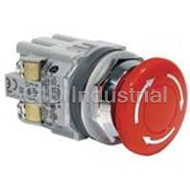
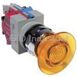
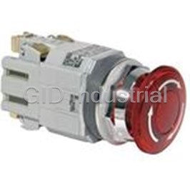
Switch Emergency Stop N.O./N.C. SPST/SPST Mushroom Button 5A 250VAC 250VDC 32N Screw Panel Mount
XW1E-LV411Q4M-R
Part Number
XW1E-LV411Q4M-R
Price
Request Quote
Manufacturer
IDEC CORPORATION
Lead Time
Request Quote
Category
Switches » Switch Emergency Stop
Specifications
Manufacturer
IDEC Corporation
Manufacturers Part #
XW1E-LV411Q4M-R
Lead Time
9 Week Lead Time
Industry Aliases
XW1E-LV411Q4M-R
Sub-Category
Emergency Stop Switches
Factory Pack Quantity
1
Datasheet

Extracted Text
Overview XW Series E-Stops Interlock Switches Enabling Switches Safety Control Light Curtains AS-Interface Safety at Work Safety ø22mm XW E-Stops ................................... 263 XW Series E-Stops www.IDEC.com/usa/estop Table of Contents LED Machine Lighting - Pg. 1 Automation & Sensing - Pg. 27 Safety - Pg. 255 Switching & Controls - Pg. 449 Index - Pg. 933 X Series E-Stops X Series E-Stops Revolutionary “Safe Break Action” Design The IDEC Emergency Stop switches, the XA, XW, and XN series, include revolutionary new technology that will change the way E-Stop switches are designed. This “safe break action” concept provides greater levels of human safety and is the first of its kind in the world! Innovative Design Conventional E-Stop switches are designed with spring pressure on the Normally Closed (NC) contacts, keeping them in the closed position and allowing the machine to operate. Improper installation or excessive force to the stop button in an emergency may break or dislodge a vital part, causing the spring loaded contact to stay closed. This situation renders the E-Stop incapable of stopping the machine, and can lead to catastrophic events, personal injury and possible loss of life. Safe Break Action Design This one-of-a-kind “safe break action” design, found only in the IDEC XA, XW, and XN series, reverses the energy direction and uses the spring-pressure to assure that the NC contacts will open if the emergency switch is damaged or the contact blocks separate due to excessive force. The NC contacts will reliably open, even if they are welded, and stop the machine. Combined with IDEC quality, this is the E-Stop switch you want in a life threatening situation. Level 4 Safety The X Series of E-Stop switches include up to four XA, XW & XN Series, The Safe Break Action E-Stops! contacts in a very compact package. In today’s automated world, more customers are requiring E-Stop switches with Internal view while removing the contact block at least three contacts. (Two of the contacts trip the power and the third contact is used to alert a safety- 1 2 3 monitoring relay.) Both the XA and XW series switches Operator offer up to four “safe-break” contacts with a depth behind the panel that is half the size of conventional E-Stop switches. This means that there is an additional contact available and the switches can be used in Level 4 Contact Block safety category applications. IDEC’s new E-Stop switches are secured from the rear of the control panel so that the E-Stop cannot be removed from the front. Another unique feature of the XA & XW NC Contact NC Contact E-Stop switches is that either a push-turn or push-pull Closed (On) Open (Off) reset method can be used to reset the switches. This eliminates any possible confusion for operators when Reach for the “Safe Break Action” resetting the switch. The durability and quality of these When the contact block is removed from the operator the main contact (NC) is forced to open (OFF). new E-Stop switches make them extremely reliable. They When removing the contact block, the cam provides a direct opening action to open the contact. can withstand the increased high stress caused by panic or a reaction to an emergency situation. Padlock E-Stops When using as a general As shown in the diagram, upon latching a traditional E-stop, it is up to the technician to verify emergency stop switch Turn the button and confirm that the machine area is clear and there are no other technicians working before Press the button. to reset. resetting the E-stop and turning on the machine. There is always a chance that the technician Button Safety might miss someone in the work area before resetting the E-stop, potentially causing injury to Latched Confirmed that person. When preventing The solution is XN4E series padlock E-Stops, which allow technicians to install their personal unauthorized resetting padlocks at the spot of actuation of the E-Stop ensuring their own safety. The diagram shows Remove Install the padlock. the padlock. how personal padlocks can be installed. Each one blocks the resetting of the E-stop until all the padlocks are removed. This provides added safety and prevents unauthorized or accidental resetting of the E-stops. A maximum of 20 padlocks can be installed by using lockout hasps. Hasp can be used. www.IDEC.com 260 AS-Interface Safety at Work Light Curtains Safety Control Enabling Switches Interlock Switches XW Series E-Stops Overview Operation allowed Overview XW Series E-Stops Interlock Switches Enabling Switches Safety Control Light Curtains AS-Interface Safety at Work X Series E-Stops X Series E-Stops Important Safety Information X Series E-Stops have lower internal energy in the “Locked” (Latching) position than in the “Normal” (Reset) position. When the switch is damaged from an excessive shock, the main contact (NC) moves toward the OFF (Safe) position. Direct Opening Action Even if the contacts are welded, the force applied on the button directly opens the contact. Rated Insulation Voltage: 250V Rated Thermal Current: 2.5A Safety Interlock Mechanism Contacts are opened when the operator is locked, and remain opened until the operator is unlocked intentionally. (IEC60947-5; 6:2) Two E-Stops in One Pushlock Pull or Turn Reset Pull Reset Turn Reset The X Series E-Stops can be reset either by pulling or turning the button. This ensures that the reset action will always be different from the make action. With traditional E-Stops, you need to choose between Push-Pull or Pushlock Turn Reset. With the IDEC X Series E-Stops you get both in one switch. XN4E, padlock type is Turn Reset only. Compact Compact Body with Four Contacts Traditional E-Stop 22mm XW and 16mm XA Series XN Series 47.7 mm 48.7mm 27.9mm ~20mm 800-262-IDEC (4332) • USA & Canada 261 X Series E-Stops X Series E-Stops Selection Guide Series XA XW XN Appearance Page see Switches & Pilot Devices section 263 see Switches & Pilot Devices section Mounting Hole 16mm 22mm 30mm Operator Type Illuminated & Non-Illuminated E-Stops: Pushlock/Turn Reset, Push-Pull Reset Action Pushlock Pull or Turn Reset (both actions available in each switch, except XN4E) Contact Configuration 1NO - 1NC, 2NC, 1NO-3NC, 4NC Electrical Life 100,000 Minimum Mechanical Life 250,000 Minimum Termination PCB & Solder Terminals Screw Terminals Operator: IP65 (IEC60529) Degree of Protection IP65 (IEC60529) Terminal: IP20 (when XW9Z-VL2MF is installed) Approvals XA series UL recognized. www.IDEC.com 262 AS-Interface Safety at Work Light Curtains Safety Control Enabling Switches Interlock Switches XW Series E-Stops Overview Overview XW Series E-Stops Interlock Switches Enabling Switches Safety Control Light Curtains AS-Interface Safety at Work 22mm XW E-Stops XW Series E-Stops 22mm XW E-Stops Key features: • The depth behind the panel is only 48.7 mm for 1 to 4 contacts (with terminal cover) for illuminated and non-illuminated units. • IDEC’s original “Safe break action” ensures that the NC contacts open when the contact block is detached from the operator. • 1 to 4NC main contacts and 1 or 2NO monitor contacts • Push-to-lock, Pull or Turn-to-reset operator • Safety lock mechanism (IEC60947-5-5, 6.2) • Degree of protection IP65 (IEC60529) • Fingersafe (IP20) terminals • Two button sizes: ø40 and ø60 mm • Push-ON illumination type available (40mm mushroom head) • Direct opening action mechanism (IEC60947-5-5, 5.2, IEC60947-5-1, Annex K) • RoHS compliant (EU directive 2002/95/EC). • UL c-UL listed. EN compliant • UL NISD category emergency stop device (File# E305148) UL File #E68961 CCC No. 2005010305150897 Specifications Applicable Standards IEC60947-5-1, EN60947-5-1, IEC60947-5-5, EN60947-5-5, UL508, UL991, CSA C22.2 No. 14 Operating Temperature Non-illuminated: –25 to +60°C (no freezing), Illuminated: –25 to +55°C (no freezing) Operating Humidity 45 to 85% RH (no condensation) Storage Temperature –45 to +80°C Push-to-lock: 32N Operating Force Pull-to-reset: 21N Turn-to-reset: 0.27N·m Minimum Force Required for 80N Direct Opening Action Min Operator Stroke Required 4mm for Direct Opening Action Maximum Operator Stroke 4.5mm Contact Resistance 50mΩ maximum (initial value) Contact Material Gold plated silver Insulation Resistance 100MΩ minimum (500V DC megger) Impulse Withstand Voltage 2.5kV Pollution Degree 3 Operation Frequency 900 operations/hour 2 2 Shock Resistance Operating extremes: 150m/s (15G), Damage limits: 1000m/s (100G) 2 Operating extremes: 10 to 500Hz, amplitude 0.35mm acceleration 50m/s Vibration Resistance 2 Damage limits: 10 to 500Hz, amplitude 0.35mm acceleration 50m/s Mechanical Life 250,000 operations minimum Electrical Life 100,000 operations minimum, (250,000 operations minimum @ 24V AC/DC, 100mA) Operator: IP65 (IEC60529) Degree of Protection Terminal: IP20 (when XW9Z-VL2MF is installed) Terminal Style M3.0 screw terminal Recommended Tightening 2.0N·m Torque for Locking Ring Wire Size 16 AWG max ø40mm: 72g Weight ø60mm: 81g 800-262-IDEC (4332) • USA & Canada 263 22mm XW E-Stops XW Series E-Stops Part Numbers Style Operator Type Monitor Contact Main Contact Part Number Non-Illuminated 1NO 1NC XW1E-BV411M-R – 2NC XW1E-BV402M-R 40mm Mushroom 2NO 2NC XW1E-BV422M-R 1NO 3NC XW1E-BV413M-R – 4NC XW1E-BV404M-R 1NO 1NC XW1E-BV511M-R – 2NC XW1E-BV502M-R 2NO 2NC XW1E-BV522M-R 60mm Mushroom 1NO 3NC XW1E-BV513M-R – 4NC XW1E-BV504M-R 1 1NO 1NC XW1E-LV411Q4M-R Illuminated – 2NC XW1E-LV402Q4M-R 40mm Mushroom LED 2NO 2NC XW1E-LV422Q4M-R with built-in 24V AC/DC LED 1NO 3NC XW1E-LV413Q4M-R – 4NC XW1E-LV404Q4M-R 2 40mm Mushroom Push-ON LED 1NO 2NC XW1E-TV412Q4M-R 1. The light is independent of the position of the switch, except for push-on LED type. 2. The light only operates when the switch is pressed as it is internally wired. XW Series EMO Switches Style NC Main Contact NO Monitor Contact Part Number 1NC - XW1E-BV401M-RH-EMO 2NC - XW1E-BV402M-RH-EMO 40mm Mushroom 3NC - XW1E-BV403M-RH-EMO 4NC - XW1E-BV404M-RH-EMO 1NC 1NO XW1E-BV411M-RH-EMO 2NC 1NO XW1E-BV412M-RH-EMO 3NC 1NO XW1E-BV413M-RH-EMO 2NC 2NO XW1E-BV422M-RH-EMO FB Enclosures with XW E-Stops Style Style NC Contact NO Contact Part Number 2NC – FB1W-XW1E-BV402MR 1NC 1NO FB1W-XW1E-BV411MR 40mm Push-lock Turn/Pull Reset 2NC 2NO FB1W-XW1E-BV422MR Non-Illuminated 3NC 1NO FB1W-XW1E-BV413MR 4NC – FB1W-XW1E-BV404MR 2NC – FB1W-XW1E-LV402MR 1NC 1NO FB1W-XW1E-LV411MR 40mm Push-lock Turn/Pull Reset 2NC 2NO FB1W-XW1E-LV422MR Illuminated* 3NC 1NO FB1W-XW1E-LV413MR 4NC – FB1W-XW1E-LV404MR 2NC – FB1W-XW1E-BV502MR For added safety, Switch 1NC 1NO FB1W-XW1E-BV511MR Guards and Nameplates can be 60mm Push-lock used with E-Stop Enclosures Turn/Pull Reset 2NC 2NO FB1W-XW1E-BV522MR Non-Illuminated 3NC 1NO FB1W-XW1E-BV513MR *LED illumination voltage: 24V AC/DC 4NC – FB1W-XW4E-BV504MR www.IDEC.com 264 AS-Interface Safety at Work Light Curtains Safety Control Enabling Switches Interlock Switches XW Series E-Stops Overview Overview XW Series E-Stops Interlock Switches Enabling Switches Safety Control Light Curtains AS-Interface Safety at Work R R R0.8 max. +0.4 ø22.3 0 22mm XW E-Stops XW Series E-Stops Contact Ratings Mounting Hole Layout øA Measurements Rated Insulation Voltage (Ui) 250V Size øA X & Y Rated Current (Ith) 5A +0.4 40mm 22.3 70mm min Rated Operating Voltage (Ue) 30V 125V 250V Y Resistive Load (AC-12) – 5A 3A AC 50/60Hz Inductive Load (AC-15) – 3A 1.5A Resistive Load (DC-12) 2A 0.4A 0.2A DC X Inductive Load (DC-13) 1A 0.22A 0.1A Resistive Load (AC-12) – 1.2A 0.6A AC 50/60Hz Inductive Load (AC-14) – 0.6A 0.3A Panel Cutout Illuminated Panel Thickness 0.8 to 6 Resistive Load (DC-12) 2A 0.4A 0.2A Panel Thickness 0.8 to 6 18.5 20.1 DC +0.2 3.2 0 Inductive Load (DC-13) 1A 0.22A 0.1A Minimum applicable load: 5V AC/DC, 1mA (reference value). The rated operating currents are measured at resistive/inductive load types specified in IEC 60947-5-1. Panel Cut-out Illuminated Unit LED Ratings Push-ON M3 Terminal Part Number Key M3 Terminal Screw Gasket 0.5 Screw Gasket 0.5 18.5 20.1 Operating Voltage Current Locking Ring Locking Ring XW1E - L V 4 11 Q4M - R 24V AC/DC ±10% 15mA Illumination Contact Configuration Color Depth Behind the Panel B: Non-Illuminated 11: 1NO - 1NC R: red L: Illuminated LED 02: 2NC RH-EMO: red with EMO Depth (mm) Description T: Illuminated 13: 1NO - 3NC engraving 48.7 1 - 4 contacts, both illuminated and non-illuminated IP20 Protection Cover Terminal Cover 47.2 Push-ON LED 04: 4NC 48.7 32 XW9Z-VL2MF XW9Z-VL2M 48.7 32 22: 2NO-2NC Voltage Code Mushroom Size 12: 1NO-2NC (Push-ON Blank: Non-illuminated 4: ø40mm LED only) Q4: Illuminated 24V AC/DC 5: ø60mm 01: 1NC (EMO switch only) (non-illuminated only) 03: 3NC (EMO switch only) Terminal Arrangements (Bottom View) 4NC 1NO-3NC 2NC 1NO-1NC 2NO-2NC 1NO-2NC Non-Illuminated Push-ON TOP TOP TOP TOP TOP TOP *1 *2 *1 *2 *3 *4 *1 *2 ∗3 ∗4 *3 *4 LED LR LR LR LR LR LR X1 X2 *2 *1 *4 *3 *4 *3 *4 *3 *4 *3 Illuminated Terminal Marking Description TOP TOP TOP TOP TO P TOP *1 *2 *1 *2 *3 *4 *3 *4 • Contact Ty pe 11 12 *3 *4 1-2: NC main contact LED LED LED LED 3-4: NO monitor contact LED LR LR LR LR LR LR • Contact Number (1-4) Starting with the contact on TOP in a 34 33 X1 *2 *1 X2 X1 *4 *3 X2 X1 *4 *3 X2 X1 *4 *3 X2 X1 *4 *3 X2 counterclockwise direction. (Example: 1NO-3NC contact) Note: 1: contact on the TOP 2: contact on the Left 3: contact on the Bottom 4: contact on the Right 800-262-IDEC (4332) • USA & Canada 265 ø40 Rated Operating Current *1 *2 *1 *2 Monitor Main Contacts (NO) Contacts (NC) *2 *1 *2 *1 *1 *2 *1 *2 *2 *1 *2 *1 *1 *2 *1 *2 37 *2 *1 *2 *1 *1 *2 *1 *2 *2 *1 *2 *1 *1 *2 *1 *2 *2 *1 *2 *1 +0.4 24.1 0 ∗1 ∗2 37 ∗2 ∗1 21 22 42 41 R R R R R R R0.8 max. R0.8 max. +0.4 ø22.3 0 +0.4 ø22.3 0 +0.4 ø22.3 0 +0.4 ø22.3 0 R0.8 max. +0.4 ø22.3 0 R0.8 max. +0.4 ø22.3 0 R0.8 max. R0.8 max. 22mm XW E-Stops XW Series E-Stops Dimensions (mm) XW Non-Illuminated (with terminal cover) XW LED Illuminated/Push-ON (with terminal cover) Panel Thickness 0.8 to 6 Illuminated Panel Thickness 0.8 to 6 18.5 20.1 Panel Thickness 0.8 to Panel Thickness 0.8 to 6 6 Panel Thickness 0.8 to 6 18.5 20.1 +0.2 +0.2 3.2 0 +0.2 0 3.2 0 3.2 Panel Cut-out Panel Cut-out Panel Cut-out M3 Terminal Screw Gasket 0.5 18.5 20.1 Locking Ring LED Push-ON Type M3 Terminal Push-ON M3 Terminal M3 Terminal Screw Gasket 0.5 M3 Terminal Screw Screw Gasket Gasket 0.5 0.5 18.5 20.1 Panel Thickness 0.8 to 6 Screw Gasket 0.5 Locking Ring 18.5 20.1 Locking Ring Locking Ring +0.2 Locking Ring 3.2 0 47.2 Terminal Cover 48.7 32 XW9Z-VL2M Panel Cut-out 32 M3 Terminal Screw Gasket 0.5 IP20 Protection Cover Terminal Cover 47.2 18.5 20.1 IP20 Protection Cover ø40mm Button 48.7 32 Terminal Cover 47.2 Locking Ring XW9Z-VL2MF XW9Z-VL2M 48.7 32 48.7 32 XW9Z-VL2MF XW9Z-VL2M 48.7 32 47.2 Terminal Cover ø40mm Button 48.7 32 XW9Z-VL2M 32 ø60mm Button EMO 0.5 +0.2 0.5 +0.2 3.2 3.2 0 0 Panel Cut-out Panel Cut-out 47.2 47.2 48.7 32.2 48.7 32.2 M3 Terminal Screw Rubber Gasket M3 Terminal Screw Rubber Gasket 18.5 20.1 18.5 20.1 Locking Ring Locking Ring Terminal Cover Terminal Cover XW9Z-VL2MF Panel Thickness 0.8 to 6 XW9Z-VL2M Panel Thickness 0.8 to 6 Accessories: Terminal Covers Accessories: Shrouds Appearance Description Part Numbers Appearance Part Numbers E-Stop Types Applicable Standards 40mm SEMI S2-0703, 12.5.1 Terminal Cover for contact block XW9Z-VL2M HW9Z-KG1 Mushroom Head Compliant 40mm, SEMI S2-0703, 12.5.1 & IP20 Fingersafe Cover XW9Z-VL2MF HW9Z-KG2 and 60mm SEMATECH Compliant Mushroom Head Accessories: Nameplates 40mm SEMI S2 Compliant Appearance Legend Part Number Inner Ø Outer Ø HW9Z-KG3 Mushroom Head (Approved by TUV) (blank) HWAV-0 22mm 60mm “Emergency Stop” HWAV-27 22mm 60mm SEMI S2 Compliant 40mm (blank) HWAV5-0 22mm 80mm HW9Z-KG4 (Approved by TUV) Mushroom Head & SEMATECH “Emergency Stop” HWAV5-27 22mm 80mm Use 60mm nameplates for 40mm mushroom buttons and 80mm nameplates for 60mm mushroom buttons. www.IDEC.com 266 ø40 ø40 ø40 ø40 ø60 ø60 ø40 ø40 37 AS-Interface Safety at Work Light Curtains Safety Control Enabling Switches Interlock Switches XW Series E-Stops Overview 37 +0.4 24.1 0 37 37 21 +0.4 24.1 0 +0.4 24.1 0 37 +0.4 0 24.1 37 37 21 +0.4 24.1 0 +0.4 0 24.1 37 Overview XW Series E-Stops Interlock Switches Enabling Switches Safety Control Light Curtains AS-Interface Safety at Work 22mm XW E-Stops XW Series E-Stops Operating Instructions Removing the Contact Block Installing the Contact Block First unlock the operator button. Grab the bayonet ring j and pull back the First unlock the operator button. Align the small t marking on the edge of the bayonet ring until the latch pin clicks k, then turn the contact block counter- operator with the small s marking on the yellow bayonet ring. Hold the contact clockwise and pull out l. block, not the bayonet ring. Press the contact block onto the operator and turn the contact block clockwise until the bayonet ring clicks. k Turn counterclockwise Bayonet Ring q marking p marking j Grab k Turn clockwise j Grab k Pull j Push Notes for installing the contact block Notes for removing the contact block Make sure that the bayonet ring is in the locked position. Check that the two 1. When the contact block is removed, the monitor contact (NO contact) is projections on the bayonet ring are securely in place. closed. Latched Unlatched 2. While removing the contact block, do not exert excessive force, otherwise the switch may be damaged. Projections 3. An LED lamp is built into the contact block for illuminated pushbuttons. When removing the contact block, pull the contact block straight to prevent damage to the LED lamp. If excessive force is exerted, the LED lamp may be damaged and fail to light. Wiring Panel Mounting The applicable wire size is 16 AWG maximum. Remove the locking ring from the operator and check that the rubber gasket is in place. Insert the operator from panel front into the panel hole. Face the side without thread on the operator with TOP marking upward, and tighten the lock- ing ring using ring wrench MW9Z-T1 to a torque of 2.0 N·m maximum. Operator without thread TOP marking Locking Ring Rubber Gasket Notes for Panel Mounting To prevent the XW emergency stop switch from rotating when resetting from the latched position, use of an anti-rotation ring (HW9Z-RL) or a nameplate is recommended. 800-262-IDEC (4332) • USA & Canada 267 22mm XW E-Stops XW Series E-Stops Screw Terminal IP20 Protection Terminal Cover XW9Z-VL2MF 1. Wire thickness: AWG18 to 16 To install the IP20 protection cover, align the TOP marking on the cover with the 2. Tighten the M3 terminal screw to a tightening torque of 0.6 to 1.0 N·m. TOP marking on the contact block, and press the cover toward the contact block. Installing and Removing Terminal Covers XW9Z-VL2M (Press) To install the terminal cover, align the TOP marking on the terminal cover with TOP marking the TOP marking on the contact block. Place the two projections on the bottom side of the contact block into the slots in the terminal cover. Press the terminal cover toward the contact block. TOP marking TOP marking 1. Once installed, the XW9Z-VL2MF cannot be removed. 2. The XW9Z-VL2MF cannot be installed after wiring. k Press the 3. With the XW9Z-VL2MF installed, crimping terminals cannot be used. terminal cover 4. Make sure that the XW9Z-VL2MF is securely installed. IP20 protection cannot be achieved when installed loosely, and electric shocks may occur. Contact Bounce When the button is reset by pulling or turning, the NC main contacts will bounce. When pressing the button, the NO monitor contacts will bounce. j Place the projections on the contact block When designing a control circuit, take the contact bounce time into consider- ation (reference value: 20 ms). To remove the terminal cover, pull out the two latches on the top side of the terminal cover. Do not exert excessive force to the latches, otherwise the latches LED Illuminated Switches may break. LED lamp is built into the contact block and cannot be replaced. TOP Markings Installing the Anti-rotation Ring HW9Z-RL Pull out the latches Align the side without thread on the operator with TOP marking, the small s marking on the anti-rotation ring, and the recess on the mounting panel. Without thread marking on the anti-rotation ring TOP marking Anti-rotation Ring (HW9Z-RL) www.IDEC.com 268 AS-Interface Safety at Work Light Curtains Safety Control Enabling Switches Interlock Switches XW Series E-Stops Overview
Frequently asked questions
How does Electronics Finder differ from its competitors?

Is there a warranty for the XW1E-LV411Q4M-R?
Which carrier will Electronics Finder use to ship my parts?
Can I buy parts from Electronics Finder if I am outside the USA?
Which payment methods does Electronics Finder accept?
Why buy from GID?

Quality
We are industry veterans who take pride in our work

Protection
Avoid the dangers of risky trading in the gray market

Access
Our network of suppliers is ready and at your disposal

Savings
Maintain legacy systems to prevent costly downtime

Speed
Time is of the essence, and we are respectful of yours
Related Products
Switch Emergency Stop N.C. SPST Mushroom Button 10A 440VAC 220VDC Screw Panel Mount AVD301N-R
Switch Emergency Stop N.C. DPST Mushroom Button 10A 440VAC 220VDC Screw Panel Mount AVD302N-R
Switch Emergency Stop N.O. SPST Mushroom Button 10A 440VAC 220VDC Screw Panel Mount AVD310N-R
Switch Emergency Stop N.O./N.C. SPST/SPST Mushroom Button 10A 440VAC 220VDC Screw Panel Mount AVD311...
Switch Emergency Stop N.C. DPST Mushroom Button 10A 440VAC 220VDC Screw Panel Mount AVLD312602DN-R
Switch Emergency Stop N.C. DPST Mushroom Button 10A 440VAC 220VDC Screw Panel Mount AVLD39902DN-R-12...
Request a Quote

The quote request has been received
Close

Facing challenges or have inquiries? Feel free to contact us!
Call Us +1-469-283-2440
What they say about us
FANTASTIC RESOURCE
One of our top priorities is maintaining our business with precision, and we are constantly looking for affiliates that can help us achieve our goal. With the aid of GID Industrial, our obsolete product management has never been more efficient. They have been a great resource to our company, and have quickly become a go-to supplier on our list!
Bucher Emhart Glass
EXCELLENT SERVICE
With our strict fundamentals and high expectations, we were surprised when we came across GID Industrial and their competitive pricing. When we approached them with our issue, they were incredibly confident in being able to provide us with a seamless solution at the best price for us. GID Industrial quickly understood our needs and provided us with excellent service, as well as fully tested product to ensure what we received would be the right fit for our company.
Fuji
HARD TO FIND A BETTER PROVIDER
Our company provides services to aid in the manufacture of technological products, such as semiconductors and flat panel displays, and often searching for distributors of obsolete product we require can waste time and money. Finding GID Industrial proved to be a great asset to our company, with cost effective solutions and superior knowledge on all of their materials, it’d be hard to find a better provider of obsolete or hard to find products.
Applied Materials
CONSISTENTLY DELIVERS QUALITY SOLUTIONS
Over the years, the equipment used in our company becomes discontinued, but they’re still of great use to us and our customers. Once these products are no longer available through the manufacturer, finding a reliable, quick supplier is a necessity, and luckily for us, GID Industrial has provided the most trustworthy, quality solutions to our obsolete component needs.
Nidec Vamco
TERRIFIC RESOURCE
This company has been a terrific help to us (I work for Trican Well Service) in sourcing the Micron Ram Memory we needed for our Siemens computers. Great service! And great pricing! I know when the product is shipping and when it will arrive, all the way through the ordering process.
Trican Well Service
GO TO SOURCE
When I can't find an obsolete part, I first call GID and they'll come up with my parts every time. Great customer service and follow up as well. Scott emails me from time to time to touch base and see if we're having trouble finding something.....which is often with our 25 yr old equipment.
ConAgra Foods