

 Manufacturers
KINGBRIGHT AA2810AQWS/D

Description
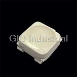
LED Uni-Color White 2-Pin Chip LED T/R
Part Number
AA2810AQWS/D
Price
Request Quote
Manufacturer
KINGBRIGHT
Lead Time
Request Quote
Category
Optoelectronics and Displays » LED
Specifications
Manufacturer
Kingbright
Manufacturers Part #
AA2810AQWS/D
Industry Aliases
AA2810AQWS/D
Sub-Category
LED Displays and Optoelectronics
Packaging
Tape and Reel
Factory Pack Quantity
2000
Datasheet

Extracted Text
AA2810AQWS/D 2.8 x 0.8 mm Right Angle SMD Chip LED Lamp DESCRIPTIONS PACKAGE DIMENSIONS � The source color devices are made with InGaN Light Emitting Diode � Electrostatic discharge and power surge could damage the LEDs � It is recommended to use a wrist band or anti-electrostatic glove when handling the LEDs � All devices, equipments and machineries must be electrically grounded FEATURES � 2.8 x 1.2 x 0.8 mm right angle SMD LED, 0.8 mm thickness � Low power consumption � Ideal for backlight and indicator � Package: 2000 pcs / reel � Moisture sensitivity level: 3 � RoHS compliant APPLICATIONS � Backlight � Status indicator RECOMMENDED SOLDERING PATTERN (units : mm; tolerance : ± 0.1) � Home and smart appliances � Wearable and portable devices � Healthcare applications ATTENTION Observe precautions for handling electrostatic discharge sensitive devices Notes: 1. All dimensions are in millimeters (inches). 2. Tolerance is ±0.1(0.0039") unless otherwise noted. 3. The specifications, characteristics and technical data described in the datasheet are subject to change without prior notice. 4. The device has a single mounting surface. The device must be mounted according to the specifications. SELECTION GUIDE [2] [1] Iv (mcd) @ 20mA Viewing A ngle Emitting Color Part Number Lens Type (Material) Min. Typ. 2θ1/2 ■ White (InGaN) AA2810AQWS/D Yellow Fluorescent 400 600 110° Notes: 1. θ1/2 is the angle from optical centerline where the luminous intensity is 1/2 of the optical peak value. 2. Luminous intensity / luminous flux: +/-15%. 3. Luminous intensity value is traceable to CIE127-2007 standards. Page 1 / 5 © 2018 Kingbright. All Rights Reserved. Spec No: DSAK2440 / 1201004743 Rev No: V.7B Date: 05/28/2018 AA2810AQWS/D ELECTRICAL / OPTICAL CHARACTERISTICS at T =25°C A Value Parameter Symbol Emitting Color Unit Typ. Max. Chromaticity Coordinates x [1] x White 0.31 - - I = 20mA F Chromaticity Coordinates y [1] y White 0.31 - - I = 20mA F Capacitance C White 100 - pF [2] Forward Voltage I = 20mA V White 3.3 4.0 V F F Reverse Current (V = 5V) I White - 50 uA R R Notes: 1. Measurement tolerance of the chromaticity coordinates is ±0.01. 2. Forward voltage: ±0.1V. 3. Excess driving current and / or operating temperature higher than recommended conditions may result in severe light degradation or premature failure. ABSOLUTE MAXIMUM RATINGS at T =25°C A Parameter Symbol Value Unit Power Dissipation P 120 mW D Reverse Voltage V 5 V R Junction Temperature T 115 °C j Operating Temperature T -40 to +85 °C op Storage Temperature T -40 to +85 °C stg DC Forward Current I 30 mA F [1] Peak Forward Current I 150 mA FM Electrostatic Discharge Threshold (HBM) 250 V - Notes: 1. 1/10 Duty Cycle, 0.1ms Pulse Width. 2. Relative humidity levels maintained between 40% and 60% in production area are recommended to avoid the build-up of static electricity – Ref JEDEC/JESD625-A and JEDEC/J-STD-033. Page 2 / 5 © 2018 Kingbright. All Rights Reserved. Spec No: DSAK2440 / 1201004743 Rev No: V.7B Date: 05/28/2018 AA2810AQWS/D TECHNICAL DATA SPATIAL DISTRIBUTION 0° -15° 15° T = 25 °C a 30° -30° -45° 45° 60° -60° -75° 75° -90° 90° 1.0 0.5 0.0 0.5 1.0 WHITE Forward Current vs. Luminous Intensity vs. Forward Current Derating Curve Luminous Intensity vs. Forward Voltage Forward Current Ambient Temperature 50 2.5 50 2.5 T = 25 °C T = 25 °C a a 40 2.0 40 2.0 30 1.5 30 1.5 20 1.0 20 1.0 10 0.5 10 0.5 0 0.0 0 0.0 2.0 2.4 2.8 3.2 3.6 4.0 0 1020 304050 -40 -20 0 20 406080 100 -40 -20 0 20 40 60 80 100 Forward voltage (V) Forward current (mA) Ambient temperature (°C) Ambient temperature (°C) CIE CHROMATICITY DIAGRAM x y x y 0.40 0.263 0.213 0.282 0.245 0.282 0.245 0.298 0.271 c0 a2 a0 0.265 0.265 0.286 0.299 0.35 0.242 0.226 0.265 0.265 b1 0.298 0.271 0.313 0.296 y 0.313 0.296 0.329 0.325 b2 b1 0.30 b2 0.306 0.332 0.329 0.371 0.286 0.299 0.306 0.332 a0 0.329 0.325 0.358 0.372 0.25 c0 a2 0.363 0.400 0.329 0.371 0.20 Notes: Shipment may contain more than one chromaticity regions. 0.20 0.25 0.30 0.35 0.40 Orders for single chromaticity region are generally not accepted. Measurement tolerance of the chromaticity coordinates is ±0.01. x Page 3 / 5 © 2018 Kingbright. All Rights Reserved. Spec No: DSAK2440 / 1201004743 Rev No: V.7B Date: 05/28/2018 Forward current (mA) Luminous intensity normalised at 20 mA Permissible forward current (mA) Luminous intensity normalised at T a = 25 °C AA2810AQWS/D REFLOW SOLDERING PROFILE for LEAD-FREE SMD PROCESS TAPE SPECIFICATIONS (units : mm) REEL DIMENSION (units : mm) Notes: 1. Don't cause stress to the LEDs while it is exposed to high temperature. 2. The maximum number of reflow soldering passes is 2 times. 3. Reflow soldering is recommended. Other soldering methods are not recommended as they might cause damage to the product. HANDLING PRECAUTIONS Compare to epoxy encapsulant that is hard and brittle, silicone is softer and flexible. Although its characteristic significantly reduces thermal stress, it is more susceptible to damage by external mechanical force. As a result, special handling precautions need to be observed during assembly using silicone encapsulated LED products. Failure to comply might lead to damage and premature failure of the LED. 1. Do not directly touch or handle the silicone lens surface. 2. As silicone encapsulation is permeable to gases, some corrosive substances S might corrode silver plating of lead frame. It may damage the internal circuitry. such as H 2 Special care should be taken if an LED with silicone encapsulation is to be used near such substances. Page 4 / 5 © 2018 Kingbright. All Rights Reserved. Spec No: DSAK2440 / 1201004743 Rev No: V.7B Date: 05/28/2018 AA2810AQWS/D PACKING & LABEL SPECIFICATIONS PRECAUTIONARY NOTES 1. The information included in this document reflects representative usage scenarios and is intended for technical reference only. 2. The part number, type, and specifications mentioned in this document are subject to future change and improvement without notice. Before production usage customer should refer to the latest datasheet for the updated specifications. 3. When using the products referenced in this document, please make sure the product is being operated within the environmental and electrical limits specified in the datasheet. If customer usage exceeds the specified limits, Kingbright will not be responsible for any subsequent issues. 4. The information in this document applies to typical usage in consumer electronics applications. If customer's application has special reliability requirements or have life-threatening liabilities, such as automotive or medical usage, please consult with Kingbright representative for further assistance. 5. The contents and information of this document may not be reproduced or re-transmitted without permission by Kingbright. 6. All design applications should refer to Kingbright application notes available at http://www.KingbrightUSA.com/ApplicationNotes Page 5 / 5 © 2018 Kingbright. All Rights Reserved. Spec No: DSAK2440 / 1201004743 Rev No: V.7B Date: 05/28/2018
Frequently asked questions
How does Electronics Finder differ from its competitors?

Is there a warranty for the AA2810AQWS/D?
Which carrier will Electronics Finder use to ship my parts?
Can I buy parts from Electronics Finder if I am outside the USA?
Which payment methods does Electronics Finder accept?
Why buy from GID?

Quality
We are industry veterans who take pride in our work

Protection
Avoid the dangers of risky trading in the gray market

Access
Our network of suppliers is ready and at your disposal

Savings
Maintain legacy systems to prevent costly downtime

Speed
Time is of the essence, and we are respectful of yours
Related Products
LED Uni-Color Orange 640nm 4-Pin PLCC T/R AA1010SE28ZC
LED Uni-Color Yellow 590nm 4-Pin PLCC T/R AA1010SY28ZC
LED Uni-Color Red 627nm 4-Pin AA1114/2EC/CC
LED Uni-Color Blue 430nm 4-Pin AA1114/2MBC/CC
LED Uni-Color Green 565nm 4-Pin AA1114/2SGC/CC
LED Uni-Color Yellow 590nm 4-Pin AA1114/2SYC/CC
Request a Quote

The quote request has been received
Close

Facing challenges or have inquiries? Feel free to contact us!
Call Us +1-469-283-2440
What they say about us
FANTASTIC RESOURCE
One of our top priorities is maintaining our business with precision, and we are constantly looking for affiliates that can help us achieve our goal. With the aid of GID Industrial, our obsolete product management has never been more efficient. They have been a great resource to our company, and have quickly become a go-to supplier on our list!
Bucher Emhart Glass
EXCELLENT SERVICE
With our strict fundamentals and high expectations, we were surprised when we came across GID Industrial and their competitive pricing. When we approached them with our issue, they were incredibly confident in being able to provide us with a seamless solution at the best price for us. GID Industrial quickly understood our needs and provided us with excellent service, as well as fully tested product to ensure what we received would be the right fit for our company.
Fuji
HARD TO FIND A BETTER PROVIDER
Our company provides services to aid in the manufacture of technological products, such as semiconductors and flat panel displays, and often searching for distributors of obsolete product we require can waste time and money. Finding GID Industrial proved to be a great asset to our company, with cost effective solutions and superior knowledge on all of their materials, it’d be hard to find a better provider of obsolete or hard to find products.
Applied Materials
CONSISTENTLY DELIVERS QUALITY SOLUTIONS
Over the years, the equipment used in our company becomes discontinued, but they’re still of great use to us and our customers. Once these products are no longer available through the manufacturer, finding a reliable, quick supplier is a necessity, and luckily for us, GID Industrial has provided the most trustworthy, quality solutions to our obsolete component needs.
Nidec Vamco
TERRIFIC RESOURCE
This company has been a terrific help to us (I work for Trican Well Service) in sourcing the Micron Ram Memory we needed for our Siemens computers. Great service! And great pricing! I know when the product is shipping and when it will arrive, all the way through the ordering process.
Trican Well Service
GO TO SOURCE
When I can't find an obsolete part, I first call GID and they'll come up with my parts every time. Great customer service and follow up as well. Scott emails me from time to time to touch base and see if we're having trouble finding something.....which is often with our 25 yr old equipment.
ConAgra Foods