

 Manufacturers
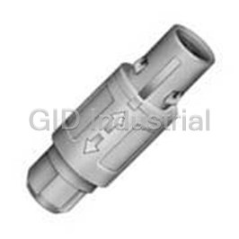
LEMO CAB.M26.GLA.C92G
Description
Conn Circular M 26 POS Solder ST Cable Mount 26 Terminal 1 Port
CAB.M26.GLA.C92G
Part Number
CAB.M26.GLA.C92G
Price
Request Quote
Manufacturer
LEMO
Lead Time
Request Quote
Category
Connectors » Connector Circular
Specifications
Manufacturer
LEMO
Manufacturers Part #
CAB.M26.GLA.C92G
Industry Aliases
CABM26GLAC92G
Sub-Category
Circular Connectors
Factory Pack Quantity
1
Datasheet

Extracted Text
PLASTIC CONNECTORS ®® No reproduction or use without express permission of editorial or pictorial content, in any manner. Table of contents 1P Series Part numbering system ......................................................................................................................................................................... 7 Shell style Standard models (IP50) ............................................................................................................................................................... 8 Elbow socket models (IP50) ...................................................................................................................................................... 12 Disposable plug ......................................................................................................................................................................... 13 Disposable socket...................................................................................................................................................................... 13 Watertight models (IP64)............................................................................................................................................................ 14 Fluidic configuration................................................................................................................................................................... 16 Mains power configuration ........................................................................................................................................................ 18 Insert configuration ........................................................................................................................................................................... 19 Alignment key .................................................................................................................................................................................... 20 Outer shell material ........................................................................................................................................................................... 20 Contact type ....................................................................................................................................................................................... 20 Colour coding..................................................................................................................................................................................... 20 Accessories........................................................................................................................................................................................ 21 Tooling ................................................................................................................................................................................................ 23 Panel hole ............................................................................................................................................................................................24 PCB drilling pattern ........................................................................................................................................................................... 24 Assembly instructions ...................................................................................................................................................................... 26 2P Series Part numbering system ....................................................................................................................................................................... 33 Shell style Standard models........................................................................................................................................................................ 34 Watertight models (IP66)........................................................................................................................................................... 37 Fluidic configuration................................................................................................................................................................... 39 Insert configuration ........................................................................................................................................................................... 40 Alignment key .................................................................................................................................................................................... 42 Outer shell material .......................................................................................................................................................................... 42 Contact type ....................................................................................................................................................................................... 42 Colour coding..................................................................................................................................................................................... 42 Accessories....................................................................................................................................................................................... 43 Tooling ................................................................................................................................................................................................ 45 Panel hole.......................................................................................................................................................................................... 46 PCB drilling pattern ........................................................................................................................................................................... 46 Assembly instructions ...................................................................................................................................................................... 48 Assembly instructions for watertight models ................................................................................................................................50 3P Series Part numbering system ....................................................................................................................................................................... 55 Shell style Standard models (IP61) ............................................................................................................................................................. 56 Insert configuration ........................................................................................................................................................................... 58 Contact type ....................................................................................................................................................................................... 59 Colour coding..................................................................................................................................................................................... 59 Accessories........................................................................................................................................................................................ 60 Fibre optic contact............................................................................................................................................................................. 61 Recommended coaxial cables.......................................................................................................................................................... 62 Tooling ................................................................................................................................................................................................ 62 Panel hole ........................................................................................................................................................................................... 65 PCB drilling pattern ........................................................................................................................................................................... 65 Assembly instructions ...................................................................................................................................................................... 66 Mechanical latching characteristics and test voltage ................................................................................................................... 68 Technical tables ................................................................................................................................................................................. 69 Product safety notice ........................................................................................................................................................................ 70 1 Precision modular connectors to suit your application Since its creation in Switzerland in 1946 the LEMO Group has been recognized as a global leader of circular Push-Pull connectors and connector solutions. Today LEMO and its affiliated companies, REDEL and COELVER, are active in more than 80 countries with the help of over 40 subsidiaries and distributors. Over 5’000 REDEL connectors The modular design of the REDEL range provides over 5’000 connectors from ø 14 mm to ø 21 mm, capable of handling cable diameters up to 9.5 mm and up to 32 contacts. This vast portfolio enables you to select the ideal connector configuration to suit almost any specific requirement in most markets, including medical devices, test and measurement instruments, machinery, audio video broadcast, telecommunications and military. REDEL’s Push-Pull Self-Latching Connection System This self-latching system is renowned worldwide for its easy and quick mating and unmating features. It provides absolute security against vibration, shock or pull on the cable, and facilitates operation in a very limited space. The REDEL self-latching system allows the connector to be mated by simply pushing the plug axially into the socket. Once firmly latched, connection cannot be broken by pulling on the cable or any other component part other than the outer release sleeve. When required, the connector is disengaged by a single axial pull on the outer release sleeve. This first disengages the latches and then withdraws the plug from the socket. UL Recognition ® REDEL connectors are recognized by the Underwriters Laboratories (UL). The approval of the complete system (REDEL connector, cable and your equipment) will be easier because REDEL connectors are recognized. CE Marking CE marking means that the appliance or equipment bearing it complies with the protection requirements of one or several European safety directives. CE marking applies to complete products or equipment, but not to electromechanical components, such as connectors. RoHS REDEL connector specifications conforms the requirements of the RoHS directive (2011/65/EU) of the European Parliament and the latest amendments. This directive specifies the restrictions of the use of hazardous substances in electrical and electronic equipment marketed in Europe. 2 REDEL connector range The REDEL connectors are plastic Push-Pull connectors. These circular plastic connectors are especially adapted for applications such as medical electronics and test & measurement. REDEL offers a wide choice of connectors with various contact configurations: multipole contacts, coaxial, fibre optics and fluidic connectors. In addition, a range of one time use connectors and connectors for mains power is available. The REDEL connectors are available in 3 sizes, depending on the cable diameter. Features & Benefits ● Aesthetically pleasing design ● Wide choice of colours for easy identification (grey, blue, yellow, black, red, green and white) ● Lightweight ● Large choice of keying to avoid cross mating ● Plastic shell made of PSU or PEI ● Various contact types: solder, crimp, print ● Extensive sterilisation (over 100 cycles) and elbow print 90º ● Excellent electrical safety (touch & scoop proof) ● Disposable models Applications ● Medical electronics ● Industrial electronics ● Test and measurement ● Automotive Series 1P 2P 3P indoor / splash proof indoor / outdoor indoor / dripping water Environment 1) Ingress IP50 / IP64 IP50 / IP66 IP61 protection Temperature PSU: -50°/ +150°C PSU: -50°/ +150°C PSU: -50°/ +150°C range PEI: -50°/ +170°C PEI: -50°/ +170°C Latching Push-Pull self latching Multipole, Hybrid: high voltage + Multipole, Hybrid: fluidic + Insulator type Multipole, Mains Power, Fluidic LV, coaxial + LV, fibre optic + LV, LV, coaxial + LV fluidic + LV Contact type Solder, crimp or print Other - - Disposable models Cable diameter 2.7 mm to 6.5 mm 3.2 mm to 9.2 mm 6.7 mm to 9.5 mm Features 6 keyways 4 keyways Insert Polarizations Note: 1) mated connector. 3 Exploded view of the REDEL 1P Straight plug backnut cable collet insulator + contacts shell Straight plug with bend relief backnut for bend relief a bend relief cable collet insulator + contacts shell Note: the bend relief must be ordered separately. Fixed socket hexagonal nut shell front nut Free socket backnut cable collet insulator + contacts shell 4 1P SERIES 1P Series A well proven connector of a small size to accomodate cable diameter up to 6.5 mm and allow up to 14 solder contacts. Top quality lightweight and rugged materials have been chosen to optimize most applications. Poly sul fone (PSU), UL certified as auto extinguishable, can be sterilized by gas or by steam. The contacts are gold-plated over copper and nickel to ensure at least 2000 mating/ unmating cycles without significantly affecting the electrical characteristics. A keying system combined with colour coding can be incor porated on most connector models to assist in the prevention of mismating. Colour coding of the plug collet nut and socket flange will give an instant visual indication of connector compatibility. Standard models (page 8 to 11) Elbow socket models (page 12) Fixed sockets Free sockets Straight plugs PA● PL● PM● PR● PP● PA● PK● PY● PR● PX● Fixed sockets PK● Disposable plug (limited use) (page 13) Watertight models (page 14 to 15) Fixed socket Straight plug PJ● PN● Disposable socket (limited use) (page 13) Free socket PF● PS● PY● Fluidic configuration (page 16 to 17) Mains power configuration (page 18) Straight plugs Fixed sockets Straight plug Fixed socket PA● PK● PAH PKH PA● PL● 6 PT● PD● Part numbering system PA G .M0 . 2G L . AC 3 9 A Plug Variant Z = cable collet and nut for fitting a bend relief Collet nut colour table: (page 20) Model: (pages 8-18) G = grey N = black A = blue R = red Keying: (page 20) J = yellow V = green B = white Contact configuration (page 19) Collet: 20 = (cable ø 1.7 mm - 2.0 mm) 39 = (cable ø 2.7 mm - 3.9 mm) 52 = (cable ø 4.0 mm - 5.2 mm) Number of contacts: (page 19) 65 = (cable ø 5.3 mm - 6.5 mm) 1) Cable fixing type: C = cable collet Outershell: G = grey PSU T = black PEI 1) N = black PSU S = grey PEI B = white Contact type: (page 20) A= male to solder C = male to crimp 2) L = female to solder Insulator: L = PEEK . . . Free socket PR G M0 2G L LC 3 9 A Variant Z = cable collet and nut for fitting a bend relief 3) Collet nut colour table : (page 20) Model: (pages 8-18) G = grey N = black A = blue R = red Keying: (page 20) J = yellow V = green B = white Contact configuration (page 19) Collet: 20 = (cable ø 1.7 mm - 2.0 mm) 39 = (cable ø 2.7 mm - 3.9 mm) 52 = (cable ø 4.0 mm - 5.2 mm) Number of contacts: (page 19) 65 = (cable ø 5.3 mm - 6.5 mm) 1) Cable fixing type: C = cable collet Outershell: G = grey PSU T = black PEI 1) N = black PSU S = grey PEI B = white Contact type: (page 20) 2) A = male to solder M= female to crimp L = female to solder Insulator: L = PEEK PK G .M0 . 2G L . Fixed socket LA Front nut colour table: (page 20) G = grey N = black Model: (pages 8-18) A = blue R = red J = yellow V = green Keying: (page 20) B = white Contact type: (page 20) Contact configuration (page 19) 2) 2) A = male to solder C = male to crimp 2) D = male for print L = female to solder Number of contacts: (page 19) M= female to crimp N = female for print V = male and female 90° for print 1) Outershell: G = grey PSU T = black PEI 1) Insulator: L = PEEK N = black PSU S = grey PEI B = white PAG.M0.2GL.AC39A Straight plug with cable collet and alignment key (G), multipole type with 2 male contacts to solder, grey PSU outershell, PEEK insulator, collet for a cable ø 2.7 to 3.9 mm and blue collet nut. PRG.M0.2GL.LC39A Free socket with cable collet and alignment key (G), multipole with 2 female contacts to solder, grey PSU outershell, PEEK insulator, collet for a cable ø 2.7 to 3.9 mm and blue collet nut. PKG.M0.2GL.LA Fixed socket with two nuts and alignment key (G), multipole type with 2 female contacts to solder, grey PSU outershell, PEEK insulator, and blue plastic front nut. ® Note: 1) for extensive steam sterilization we recommend Polyetherimide ULTEM (PEI). 2) contact available only with H and J keying and with 8, 10 or 14 contacts (inverted contacts). 3) collet nut and front nut colour table for PT and PD models. 7 P .. M . Standard models (IP50) Straight plug Fixed socket 2 4 3 1 5 1 67 2 8 9 1 Outershell 1 Outershell 2 Insulator 2 Insulator 6 Latch sleeve 3 Female contact 7 Male contact 4 Hexagonal nut 8 Cable collet 5 Front nut 9 Backnut Characteristics Value Standards Characteristics Value Standards Endurance (latching) > 2000 cycles IEC 60512-5 test 9a Average retention force when 90 N IEC 60512-8 test 15f pulling on the cable 1N = 0.102 kg Working temperature range (PSU) -50/+150°C – Working temperature range (PEI) -50/+170°C – Cable retention force (depends on 50 - 150 N IEC 60512-9 test 17c cable construction) 1N = 0.102 kg PAG Straight plug, key (G) or keys (A, B, C, H and J), with cable collet Cable ø Part Number min max PAG.M.GL.AC20G 1.7 2.0 PAG.M .GL.AC39G 2.7 3.9 PAG.M .GL.AC52G 4.0 5.2 PAG.M .GL.AC65G 5.3 6.5 Note: replace . by contact configuration (see page 19). ~45 ~30 PAG Straight plug, key (G) or keys (A, B, C, H and J), with cable collet and nut for fitting a bend relief Cable ø Part Number min max PAG.M .GL.AC20GZ 1.7 2.0 PAG.M .GL.AC39GZ 2.7 3.9 PAG.M .GL.AC52GZ 4.0 5.2 PAG.M.GL.AC65GZ 5.3 6.5 Note: replace by contact configuration (see page 19).. ~48 The bend relief must be ordered separately (see page 22). ~43.7 ~28.7 S 9 Note: all dimensions are in millimeters 8 ş 14 ş 14 P .. M . PLG Fixed socket, key (G) or keys (A, B, C, H and J), nut fixing Contact number of Part Number Solder Crimp Print contacts N a max N a c ø d PLG.M0.2GL.LG 2 20.5 2.5 22.2 0 5 0.7 PLG.M0.4GL.LG 4 20.5 2.5 22.2 0 5 0.7 5 20.5 2.5 22.2 0 5 0.7 PLG.M0.5GL.LG PLG.M0.6GL.LG 6 20.5 2.5 22.2 0 3 0.5 PLG.M0.7GL.LG 7 20.5 4.5 22.2 0 3 0.5 PLG.M0.8GL.LG 8 20.5 4.5 22.2 0 3 0.5 a N PLG.M0.9GL.LG 9 20.5 3.9 – – 3 0.5 S17 4 1 20.5 PLG.M1.0GL.LG 10 20.5 3.9 – – 3 0.5 PLG.M1.4GL.LG 14 20.5 3.9 – – 3 0.5 Note: for PCB drilling pattern and panel hole see page 24. c S12.5 9 maxi Solder + Crimp Print PKG Fixed socket, key (G) or keys (A, B, C, H and J), with two nuts (back panel mounting) Contact number of Part Number Solder Crimp Print contacts N a max N a c ø d PKG.M0.2GL.LG 2 20.5 2.5 22.2 0 5 0.7 PKG.M0.4GL.LG 4 20.5 2.5 22.2 0 5 0.7 PKG.M0.5GL.LG 5 20.5 2.5 22.2 0 5 0.7 6 20.5 2.5 22.2 0 3 0.5 PKG.M0.6GL.LG PKG.M0.7GL.LG 7 20.5 4.5 22.2 0 3 0.5 PKG.M0.8GL.LG 8 20.5 4.5 22.2 0 3 0.5 a N PKG.M0.9GL.LG 9 20.5 3.9 – – 3 0.5 S17 4 1 20.5 PKG.M1.0GL.LG 10 20.5 3.9 – – 3 0.5 14 20.5 3.9 – – 3 0.5 PKG.M1.4GL.LG Note: for PCB drilling pattern and panel hole see page 24. c S12.5 9 maxi Solder + Crimp Print PKG Fixed socket, key (G) or keys (A, B, C, H and J), with two nuts, with 90° contacts (back panel mounting) number of Part Number L contacts PKG.M0.2GL.VG 2 5.4 PKG.M0.4GL.VG 4 5.2 PKG.M0.5GL.VG 5 7.7 PKG.M0.6GL.VG 6 7.7 PKG.M0.7GL.VG 7 7.7 L 20.5 PKG.M0.8GL.VG 8 7.7 S17 4 PKG.M0.9GL.VG 9 10.3 PKG.M1.0GL.VG 10 10.3 PKG.M1.4GL.VG 14 12.9 Note: for PCB drilling pattern see page 25. Panel hole see page 24. A A S12.5 9 maxi 2 Note: all dimensions are in millimeters 9 M14 x 1 M14 x 1 20 mini M14 x 1 19.5 19.5 ş d ş d 19.5 P .. M . PMG Fixed socket, key (G) or keys (A, B, C, H and J), with square flange Contact number of Part Number Solder Crimp Print contacts N a max N a c ø d PMG.M0.2GL.LG 2 20.5 2.5 22.2 0 5 0.7 PMG.M0.4GL.LG 4 20.5 2.5 22.2 0 5 0.7 5 20.5 2.5 22.2 0 5 0.7 PMG.M0.5GL.LG PMG.M0.6GL.LG 6 20.5 2.5 22.2 0 3 0.5 PMG.M0.7GL.LG 7 20.5 4.5 22.2 0 3 0.5 N PMG.M0.8GL.LG 8 20.5 4.5 22.2 0 3 0.5 N PMG.M0.9GL.LG 9 20.5 3.9 – – 3 0.5 4 a 4 PMG.M1.0GL.LG 10 20.5 3.9 – – 3 0.5 PMG.M1.4GL.LG 14 20.5 3.9 – – 3 0.5 Note: for PCB drilling pattern see page 24. Panel hole see page 24. c S12.5 S12.5 1 Solder + Crimp Print PYG Fixed socket, snap-on fixing key (G) or keys (A, B or H), Solder number of Part Number contacts a max 2 2.5 PYG.M0.2GL.LG 4 PYG.M0.4GL.LG 2.5 PYG.M0.5GL.LG 5 2.5 PYG.M0.6GL.LG 6 2.5 PYG.M0.7GL.LG 7 2.5 2.5 a 26.7 PYG.M0.8GL.LG 8 PYG.M0.9GL.LG 9 4.0 7.5 PYG.M1.0GL.LG 10 4.0 PYG.M1.4GL.LG 14 4.0 Note: only with A, B or G keying (2 to 14 contacts) or H (8,10 or 14 contacts). The insulator is made of PEEK. PRG Free socket, key (G) or keys (A, B, C, H and J), with cable collet Cable ø Part Number min max PRG.M .GL.LC20G 1.7 2.0 PRG.M .GL.LC39G 2.7 3.9 PRG.M.GL.LC52G 4.0 5.2 PRG.M .GL.LC65G 5.3 6.5 Note: replace . by contact configuration (see page 19). ~40 Note: all dimensions are in millimeters 10 M14 x 1 ş 14 25 M14 x 1 şd ø 16 25 P .. M . PRG Free socket, key (G) or keys (A, B, C, H and J), with cable collet and nut for fitting a bend relief Cable ø Part Number min max PRG.M .GL.LC20GZ 1.7 2.0 2.7 3.9 PRG.M.GL.LC39GZ PRG.M .GL.LC52GZ 4.0 5.2 PRG.M .GL.LC65GZ 5.3 6.5 Note: replace . by contact configuration (see page 19). ~43 The bend relief must be ordered separately (see page 22). ~38.7 S 9 PTG Fixed socket, key (G) or keys (A, B, C, H and J), with two nuts and cable collet (back panel mounting) Cable ø Part Number min max PTG.M.GL.LC20G 1.7 2.0 PTG.M.GL.LC39G 2.7 3.9 PTG.M.GL.LC52G 4.0 5.2 5.3 6.5 PTG.M.GL.LC65G Note: replace . by contact configuration (see page 19). Panel hole see page 24. ~40 S12.5 4 S17 9 maxi PDG Fixed socket, key (G) or keys (A, B, C, H and J), nut fixing and cable collet Cable ø Part Number min max PDG.M .GL.LC20G1.7 2.0 PDG.M.GL.LC39G 2.7 3.9 PDG.M .GL.LC52G 4.0 5.2 PDG.M .GL.LC65G 5.3 6.5 Note: replace by contact configuration (see page 19).. Panel hole see page 24. ~40 S12.5 4 9 maxi S17 Note: all dimensions are in millimeters 11 ø19.5 ş 14 ø 19.5 M14 x 1 M14 x 1 P .. . Elbow socket models (IP50) PPG Elbow socket, key (G) or keys (A, B, C), for printed circuit number of Part Number contacts PPG.M0.2GG.N 2 PPG.M0.4GG.N 4 PPG.M0.5GG.N 5 6 PPG.M0.6GG.N PPG.M0.7GG.N 7 14.8 PPG.M0.8GG.N 8 PPG.M0.9GG.N 9 PPG.M1.0GG.N 10 Note: only available with G or A, B, C keying. The insulator is made of PSU. Outershell material is grey or black PSU. For PCB drilling, see page 25. It is possible to replace the 4 ground pins by 4 screws (M1.6) add an «S» to the end of the part number. (e.g.: PPG.M0.2GG.NS) 30.2 14.8 18.5 M 1.6 PXG Elbow socket, key (G) or keys (A, B, C), with two nuts, for printed circuit number of Part Number contacts PXG.M0.2GG.NG 2 PXG.M0.4GG.NG 4 PXG.M0.5GG.NG 5 PXG.M0.6GG.NG 6 PXG.M0.7GG.NG 7 6.9 max. 4 PXG.M0.8GG.NG 8 PXG.M0.9GG.NG 9 14.8 PXG.M1.0GG.NG 10 Note: only available with G or A, B, C keying. The insulator is made of PSU. Outershell material is grey or black PSU. For PCB drilling, see page 25. Panel hole see page 24. It is possible to replace the 4 ground pins by 4 screws (M1.6) add an «S» to the end of the part number. (e.g.: PXG.M0.2GG.NGS) 30.2 S17 4 14.8 6.9 maxi S12.5 M 1.6 18.5 Note: all dimensions are in millimeters. For outershell in black PSU replace material code by «N». 12 3 14.5 15.9 3 14.5 15.9 M14x1 M14x1 ş 13.4 ş 13.4 19.2 PJ .. M . A Disposable plug (limited use) Characteristics Value Standards Fixed socket 4 1 3 2 1) Endurance for PJl (latching) 15 cycles min. IEC 60512-5 test 9a 1 Outershell Working temperature range (ABS) -30 / +90°C – 2 Latch sleeve Outershell / insulator material PSU – 3 Male contact Backshell material ABS – 4 Backshell 1) Note: with machined contacts PJG Straight disposable plug Figure 1 PJ G . M1 . 0G G . AG Keying: A, B, C, G Colour: Number of contacts: B = white 7, 9, 10, 14 G = grey Figure 2 PJ G 138 . . AG Figure 1 Figure 2 ø C (mm): 3.8 mm = 138 Colour: Material: B = white A = ABS G = grey Solder contacts 23.5 24 Note: 7 pin ø 0.7 mm male with ø 0.8 mm solder buckets. 9, 10 and 14 pin ø 0.5 mm male with ø 0.44 mm solder buckets. Not intended for use with PNor PYsockets. PY .. M . Disposable socket (limited use) Characteristics Value Standards 1 2 Endurance for PYl (latching) > 2000 cycles IEC 60512-5 test 9a Fixed socket Working temperature range (PSU) -50/+150°C – 1 Outershell Average latching force 6N IEC 60512-7 test 13a 2 Male contact Average unmating force 7N IEC 60512-7 test 13a Average retention force 90N IEC 60512-7 test 13a PYl Fixed disposable socket, snap on fixing nb. Recommanded Contact Solder Shell Part Number of Mating straight Type a max color cts. plug part number PYG.M0.4GG.LG 4 female 2.5 grey PAG.M0.4GL.AC PYG.M0.4GG.LN 4 female 2.5 black PAG.M0.4GL.AC PYH.M0.8GG.AA 8 male 2.5 blue PAH.M0.8GL.LC PYH.M0.8GG.AB 8 male 2.5 white PAH.M0.8GL.LC PYA.M1.0GG.LG 10 female 4.0 grey PAA.M1.0GL.AC PYH.M1.0GG.AA 10 male 4.0 blue PAH.M1.0GL.LC 26.7 a Note: The outershell and the insulator are moulded out of the same material (PSU). 7.5 Protective backshell available (see page 22). Part number last digit represents the colour. Note: all dimensions are in millimeters 13 ø 14 ø 16 3.8 ø 14 P .. . Watertight models (IP64 when mated) Fixed socket Straight plug 2 4 3 1 5 6 7 1 89 2 10 6 7 1 Outershell 1 Outershell 2 Insulator 2 Insulator 3 Female contact 6 Gasket 4 Hexagonal nut 7 Nut 5 Flat gasket 8 Latch sleeve 6 Gasket 9 Male contact 7 Nut 10 Cable collet Characteristics Value Standards Characteristics Value Standards Endurance (latching) > 2000 cycles IEC 60512-5 test 9a Average retention force when 90 N IEC 60512-8 test 15f pulling on the cable 1N = 0.102 kg Working temperature range (PSU) -50/+90°C – Gasket material Elastomer SEBS – Cable retention force (depends on 50 - 150 N IEC 60512-9 test 17c cable construction) 1N = 0.102 kg PFG Straight plug with cable collet and nut for fitting a bend relief Cable ø Part Number min max PFG.M.GL.AC20GZ 1.7 2.0 PFG.M.GL.AC39GZ 2.7 3.9 PFG.M.GL.AC52GZ 4.0 5.2 PFG.M.GL.AC65GZ 5.3 6.5 Note: the bend relief must be ordered separately (see page 22). ~48 Replace . by contact configuration (see page 19). ~43.7 ~28.7 S 9 PNG Fixed socket, nut fixing Contact number of Part Number Solder Crimp Print contacts N a max N a c ø d PNG.M0.2GL.LG 2 23.3 2.5 25.0 0 5 0.7 4 23.3 2.5 25.0 0 5 0.7 PNG.M0.4GL.LG 5 23.3 2.5 25.0 0 5 0.7 PNG.M0.5GL.LG PNG.M0.6GL.LG 6 23.3 2.5 25.0 0 3 0.5 PNG.M0.7GL.LG 7 23.3 4.5 25.0 0 3 0.5 PNG.M0.8GL.LG 8 23.3 4.5 25.0 0 3 0.5 a N PNG.M0.9GL.LG 9 23.3 3.9 – – 3 0.5 S 17 1 23.3 PNG.M1.0GL.LG 10 23.3 3.9 – – 3 0.5 7.5 PNG.M1.4GL.LG 14 23.3 3.9 – – 3 0.5 Note: for PCB drilling pattern see page 24. c S 12.5 8.5 maxi Solder + Crimp Print Note: all dimensions are in millimeters 14 M14 x 1 ş 18.5 ş d ş 14 P .. . PSG Free socket, conical outershell with cable collet and nut for fitting a bend relief Cable ø Part Number min max PSG.M.YL.LC52NZ 4.0 5.2 PSG.M.YL.MC65RZ 5.3 6.5 PSG.M .YL.MC65AZ5.3 6.5 PSG.M.YL.LC52NZ 4.0 5.2 Note: replace . by contact configuration (see page 19). ® Outershell in black Delrin ~46 The bend relief must be ordered separately (see page 22) . 32 S 9 Note: all dimensions are in millimeters 15 18.5 P .. A0 1G Z. Fluidic configuration (2 bars) The REDEL fluidic connector has many applications for example in medical or dentistry equipment. The connector is a monotube type and primarily intended for use with air or inert gas. Straight plug 4 2 1 3 1 6 5 2 7 8 Fixed socket 1 Outershell 1 Outershell 2 Fluidic tube 2 Fluidic tube 5 Latch sleeve 3 Front nut 6 O-ring 4 Hexagonal nut 7 Cable collet 8 Backnut Characteristics Value Standards Characteristics Value Standards Max. working pressure 2 bars – Inner fluidic contact diameter 2.6 mm – Endurance (latching) > 2000 cycles IEC 60512-5 test 9a Tube diameter inner/outer 4 mm / 6 mm – Working temperature range (PSU) -20/+150ºC – Fluidic tube material Ni plated brass – ® O-ring material FPM (Viton)– PAG Straight plug, key (G) or keys (A, B, C, H and J), with cable collet ø max. tube ø inner tube Part Number (mm) (mm) PAG.A0.1GZ.ZC65G 6.5 4 Note: For collet nut colour replace last digit (see table page 20). ~45 ~30 PAG Straight plug, key (G) or keys (A, B, C, H and J), with cable collet and nut for fitting a bend relief ø max. tube ø inner tube Part Number (mm) (mm) PAG.A0.1GZ.ZC65GZ 6.5 4 The bend relief must be ordered separately (see page 22). ~48 ~43.7 ~28.7 S 9 Note: all dimensions are in millimeters 16 ş 14 ş 14 P .. A0 1G Z. PLG Fixed socket, key (G) or keys (A, B, C, H and J), with fluidic contact, nut fixing ø inner tube Part Number (mm) PLG.A0.1GZ.ZG 4 Note: For front nut colour replace last digit (see table page 20). Recommended tube Legris 102540601 32.5 19.7 S17 4 S12.5 9 maxi PKG Fixed socket, key (G) or keys (A, B, C, H and J), with fluidic contact, with two nuts (back panel mounting) ø inner tube Part Number (mm) PKG.A0.1GZ.ZG 4 Note: For front nut colour replace last digit (see table page 20). Recommended tube Legris 102540601 32.5 19.7 S17 4 S12.5 9 maxi Note: all dimensions are in millimeters 17 M14 x 1 M14 x 1 19.5 19.5 P .. . Mains power configuration The new PAl and PKl models are used for mains power in medical applications. The design of a special insulator offers the required creepage distance. The 3 contacts are only solder type with a maximum AWG 18 (wire size max 1.35 mm). The connectors are UL certified to be used at 250 Volt AC (9 Amps). See UL approval file number N°E242949 (only valid for 3 contact configuration). 4 1 2 3 5 6 7 8 Fixed socket Straight plug 1 Outershell 5 Latch sleeve 2 male contact 6 Female contact 3 Front nut 7 Cable collet 4 Hexagonal nut 8 Backnut Characteristics Value Standards Characteristics Value Standards Test voltage (rms) 1.5 kV IEC 60512-2 test 4a Cable retention force (depends on 50 – 150 N IEC 60512-9 test 17c cable construction) 1N = 0.102 kg Rated voltage (rms) 250 V IEC 60601/UL 60601-1 Endurance (latching) > 2000 cycles IEC 60512-5 test 9a Average retention force when pulling 90 N IEC 60512-8 test 15f on the cable 1N = 0.102 kg Working temperature range (PSU) -50/+150°C – UL file number E242949 – PAl Straight plug, key (H or G), with cable collet and nut for fitting a bend relief Cable ø Part Number min max PAH.N0.3GL.LC52GZ 4.0 5.2 PAH.N0.3GL.LC65GZ 5.3 6.5 PAG.N0.4GL.AC52GZ 4.0 5.2 PAG.N0.4GL.AC65GZ 5.3 6.5 Note: The bend relief must be ordered separately (see page 22) . ~48 ~43.7 ~28.7 S 9 PKl Fixed socket, key (H or G), with two nuts (back panel mounting) Part Number PKH.N0.3GL.AG PKG.N0.4GL.LG Note: For front nut colour replace last digit (see table page 20). Not available with print contact. 27.3 S17 4 S12.5 9 maxi Note: all dimensions are in millimeters 18 M14 x 1 19.5 ù 14 P .. . Insert configuration Male solder contact Female solder contacts Contact type 1 4 4 1 3 2 3 2 Male crimp contact Female crimp contacts M0.2 2 1.3 1.10 1.4 1.20 1.30 10.0 M0.4 4 0.9 0.80 1.1 1.20 1.20 8.0 M0.5 5 0.9 0.80 1.1 1.05 0.80 7.0 M0.6 6 0.7 0.60 0.8 1.05 0.85 6.0 M0.7 7 0.7 0.60 0.8 1.05 0.85 5.0 M0.8 8 0.7 0.60 0.8 1.05 0.60 5.0 M0.9 9 0.5 0.45 - - 0.85 0.60 3.0 4) M1.0 10 0.5 0.45 - - 0.85 0.45 3.0 M1.4 14 0.5 0.45 - - 0.60 0.50 2.0 2.00 6) 6) N0.3 3 0.9 1.40 - - - - 1.50 9.0 6.00 1.30 N0.4 4 0.9 1.40 - - - - 2.50 8.0 3.50 A0.1 1 Fluidic (monotube) up to 2 bars Note: 1) depending on specific application and related standard, more restrictive operating voltage may apply. We suggest operating voltage = 1/3 test voltage, see page 68. 2) shortest distance in air between two conductive parts. 3) shortest distance along the surface of the insulating material between two conductive parts. 4) for PPG and PXG (with 10 contacts) electrical characteristics, please contact factory. 5) for a given AWG, the diameter of some stranded conductor design is larger than the solder cup diameter (see page 69). 6) UL file number: E242949 19 Fluidic Mains power Multipole ø A ø A Reference Number of contacts Contact ø (mm) 5) Solder bucket ø (mm) 5) Crimp bucket ø (mm) Solder Crimp Print (straight) Print (elbow) 1) Test voltage (kV rms) Contact-contact 2) Air clearance min (mm) 3) Creepage distance min (mm) Rated current (A) 205° 170° P .. . Alignment key Verify the third digit of the part number in order to select the right keying. The standard keying is «G» coded. 0 40° 60° 80° Keying (plug front view) Reference GA B C HJ Contact type for plug male male male male female female Contact type for socket female female female female male male Number of contacts 2 to 14 8, 10 or 14 P .. . Outer shell material Material Colour Temperature PEI SGrey -50° / +170°C PEI T Black PSU GGrey -50° / +150°C N Black PSU Note: for extensive sterilization use PEI. For complete connector in PEI (collet nut, front nut or flange also in PEI), available colours are grey or black only. Use colour coding grey or black according to colour coding table (see below) .. . P Contact type Select the type of contact: solder or crimp? When should I use crimp rather than solder contacts ? Type Male Female Soldering 1) Plug solder AL recommended for small volumes crimp C- requires little amount of tooling (soldering iron) requires more time Type Male Female Crimping 1) Socket solder A L recommended for large volumes crimp -M no heat is required to make the connection print DN for contacts with high density print 90º VV for use in high temperature environment 1) Note: only for H and J keying with 8, 10 or 14 contacts requires extra tooling (crimping tools) For complete connector in PEI (collet nut, front nut or flange also in PEI), available colours are grey or black only. Use colour coding grey or black according to colour coding table (see below) P .. . Colour coding Colours grey blue yellow black red green white Reference GA J NR V B Note: the RAL colours are indicative and depend on raw material and production RAL code 7001 5002 1016 9005 3020 6024 9003 process. Colour may differ. Easy identification with the assistance of colour coding. Outershell is only available in grey or black. 20 Ref. Accessories PAG-PLG Insulator for crimp contacts PAG-PKG Crimp contacts, kit with the number of contacts in a tube male / white marking female / red marking Insulator part number Kit contact part number Contact Contact nb. of ø contact configuration configuration contacts (mm) For male contact For female contact Male Female M0.2 PAG.302.YL PLG.402.YL M0.2 2 1.3 PAG.567.02C PKG.667.02M M0.4 PAG.304.YL PLG.404.YL M0.4 4 0.9 PAG.562.04C PKG.662.04M M0.5 PAG.305.YL PLG.405.YL M0.5 5 0.9 PAG.562.05C PKG.662.05M PAG.306.YL PLG.406.YL M0.6 6 0.7 PAG.557.06C PKG.657.06M M0.6 M0.7 PAG.307.YL PLG.407.YL M0.7 7 0.7 PAG.557.07C PKG.657.07M M0.8 PAG.308.YL PLG.408.YL M0.8 8 0.7 PAG.557.08C PKG.657.08M Note: upon request, contacts with reduced crimp barrel are available. PLA Collet Cable ø (mm) ø A Part Number (mm) min. max. PLA.720.2.0 1.7 2.0 PLA.739.3.9 2.7 3.9 PLA.752.5.2 4.0 5.2 PLA.765.6.5 5.3 6.5 Note: = UG (grey PSU), TN (black PEI) or UN (black PSU). PKG Plastic front nut for PKl and PTl models Part Number Mat. Colours PKG.220.UA PSU blue ş 18.5 PKG.220.UB PSU white PKG.220.UG PSU grey M14 x 1 4 PKG.220.UJ PSU yellow PKG.220.UN PSU black PKG.220.UR PSU red PKG.220.UV PSU green PKG.220.TG PEI grey PKG.220.TN PEI black PAM.130.ll Nut for fitting a GMA.1B bend relief Part Number Mat. Colours 25.5 PAM.130.UA PSU blue 21.2 PAM.130.UB PSU white PAM.130.UG PSU grey PAM.130.UJ PSU yellow PAM.130.UN PSU black PAM.130.UR PSU red S 9 PAM.130.UV PSU green PAM.130.TN PEI black PAM.130.TG PEI grey Note: all dimensions are in millimeters Note: only for PA , PRor PT models. 21 ø 6.5 ş A ş 6.5 ø 11.2 PBG.200.BMV Blanking cap for REDEL P 16 10 0.35 Note: with PNG socket model it offers IP64. ® Material: Delrin , colours: black PYG.0_ Protective backshell for PYl PY G 02 7Y G 0P S U . . . L ø C (mm): Material: 2.5 mm = 02.5 ABS 2.7 mm = 02.7 PSU 3.8 mm = 03.8 Color: Length: A = Blue 0 = 47 mm B = White 1 = 67.1 mm G = Grey J = Yellow N = Black R = Red V = Green PYG.0_ PYNote: Length 47 mm can be delivered in 3 different diameters 2.5/2.7/3.8 mm. Length 67 mm can be delivered in 2 different diameters 2.5 and 2.7 mm. GMA.1B Bend relief A bend relief absorbs the force that may be exerted on cables. These are designed for plugs and free sockets with cable collet and nut. L Dimensions (mm) Temperature range Reference Colours Part Number Bend relief Cable ø Material in dry atmosphere in water steam A L max. min. A blue GMA.1B.025.DG 2.5 30 2.9 2.5 B white GMA.1B.030.DG 3.0 30 3.4 3.0 G grey GMA.1B.035.DG 3.5 30 3.9 3.5 J yellow TPU (Thermoplastic GMA.1B.040.DG 4.0 30 4.4 4.0 -40°C, +80°C – M brown Polyurethane) GMA.1B.045.DG 4.5 30 4.9 4.5 N black GMA.1B.054.DG 5.4 30 6.0 5.4 R red 1) GMA.1B.065.DG 6.5 30 7.0 6.5 S orange V green GMA.1B.025.RG 2.5 34 2.9 2.5 GMA.1B.030.RG 3.0 34 3.4 3.0 Note: the selection of pigments, which should remain stable at high temperature, is GMA.1B.035.RG 3.5 34 3.9 3.5 limited by the new regulations. For this Silicone GMA.1B.040.RG 4.0 34 4.4 4.0 reason, some colours will be a shade different elastomer -60°C, +200°C +140°C from those used for TPU bend reliefs. The GMA.1B.045.RG 4.5 34 5.0 4.5 VMQ selected solutions represent the best GMA.1B.051.RG 5.1 34 5.6 5.1 possible compromise. GMA.1B.057.RG 5.7 34 6.2 5.7 GMA.1B.063.RG 6.3 34 7.0 6.3 1) Note: Design may differ from other bend relief, model without stripes. The last letter «G» of the part number indicates a grey colour, see the adjacent table and replace letter «G» by the letter of the colour required. All dimensions are in millimeters 22 ş C ø 13.3 ø 3.5 90 101.7 ø A ş 15.8 Tooling POP.125.GN Spanner for outershell POB.186.GN Spanner for front nut 34 ş 21 12.5 95 Note: both spanners available as a kit, ref. POZ.12.18G.N. Material: PA 6.6 Material: PA 6.6 DPC.91.701.V Crimping tool DCE Positioners for crimp contacts male female DCF Automatic extraction tools for crimp contacts Positioner part number Part number extractor Contact ø Conductor Selector No Configuration (mm) AWG Setting Male contact Female contact Male contact Female contact M0.2 1.3 18-20 DCE.91.135.BVD DCE.91.130.BVM DCF.91.133.5LT DCF.91.131.2LT 8-7 M0.4/M0.5 0.9 20-22-24 DCF.91.093.5LT DCF.91.090.2LT DCE.91.095.BVD DCE.91.090.BVM 6-5-5 M0.6/M0.7/M0.8 0.7 22-24-26 DCF.91.073.5LT DCF.91.070.2LT DCE.91.075.BVD DCE.91.070.BVM 6-5-5 Note: the variance in conductor stranding diameter for the minimum AWG is such that some can have a cross section which is not sufficient to guarantee crimping as per IEC 60352-2 standard. All dimensions are in millimeters. DCK Retention testing tools for crimp contacts F Testing tool part number Contact ø Test force (mm) (N) Male contact Female contact DCK.91.071.0LRC DCK.91.071.0LRM 0.7 10 0.9 14 DCK.91.091.4LRC DCK.91.091.4LRM 1.3 25 DCK.91.132.5LRC DCK.91.132.5LRM Note: all dimensions are in millimeters 23 5.8 24 ' 6 72 ° 2 60° ° 45 1 5 30° ° 22°30' 22°30' 18° Panel hole For PLl, PKl, PNl, PXl, PTl and PDl For PMl 12.6 ± 0.05 12.6 ± 0.05 23.5 min. ş 2.6 26 min. Note: PYis also designed for snap-on fixing into customer housing. Consult factory for information. – Socket mounting nut torque = 1.5 Nm. PCB drilling pattern For straight contacts 90° 60° +0.1 2 x ø 0.8 0 +0.1 5 x ø 0.8 0 +0.1 +0.1 6 x ø 0.6 0 4 x ø 0.8 0 M0.2 M0.4 M0.5 M0.6 45° 45° +0.1 +0.1 7 x ø 0.6 0 8 x ø 0.6 0 +0.1 + 0.1 9 x ø 0.6 10 x ø 0.6 0 0 M0.7 M0.8 M0.9 M1.0 36° +0.1 14 x ø 0.6 1.8 0 M1.4 Note: all dimensions are in millimeters 24 1.9 ø 2.8 ø 3.7 ø 4.4 + 0.1 ş 14.0 0 ø 3.4 ø 3.8 18.2 ± 0.1 ø 3.4 ø 3.9 1.4 + 0.1 ş 14.0 0 ø 3.7 ø 3.95 For 90° elbow contacts (A-A view) 2.54 2.54 2.54 5 2.54 4 4 3 1 1 2 3 1 2 2 +0.1 2 x ø 0.9 0 AA +0.1 4 x ø 0.7 0 +0.1 5 x ø 0.7 0 M0.2 M0.4 M0.5 2.54 2.54 2.54 2.54 2.54 2.54 2.54 2.54 5 7 6 76 6 5 6 4 5 8 5 1 8 9 1 74 1 3 4 1 4 2 2 3 2 3 2 3 +0.1 7 x ø 0.7 0 2.54 1.27 1.27 +0.1 +0.1 +0.1 8 x ø 0.7 9 x ø 0.7 6 x ø 0.7 0 0 0 M0.6 M0.7 M0.8 M0.9 2.54 2.54 2.54 2.54 8 9 7 7 6 10 14 6 8 5 11 13 9 10 1 5 12 1 4 2 4 2 3 3 2.54 +0.1 14 x ø 0.7 +0.1 0 10 x ø 0.7 0 M1.0 M1.4 For PPG and PXG models + +0.1 +0.1 0.1 +0.1 2 x ş 0.8 4 x ş 0.8 5 x ş 0.8 6 x ø 0.8 0 0 0 0 + +0.1 + 0.1 0.1 + 0.1 4 x ş 0.8 4 x ş 0.8 4 x ş 0.8 0 0 0 4 x ø 0.8 0 2 4 3 5 4 5 6 4 1 12 12 3 1 2 3 1.27 1.27 2.54 2.54 2.54 2.54 (2x) 1.27 8.89 8.89 1.27 8.89 8.89 M0.4 M0.5 M0.6 M0.2 +0.1 +0.1 +0.1 +0.1 8 x ø 0.8 7 x ø 0.8 0 9 x ø 0.8 10 x ø 0.8 0 0 0 +0.1 +0.1 +0.1 +0.1 4 x ø 0.8 4 x ø 0.8 0 4 x ø 0.8 4 x ø 0.8 0 0 0 6 6 6 6 5 7 5 8 7 8 7 4 5 5 1 8 9 7 9 10 2 1 2 3 1 2 1 2 3 4 4 4 3 3 (4x) 1.27 (4x) 1.27 (4x) 1.27 (4x) 1.27 8.89 8.89 8.89 8.89 M0.7 M0.8 M0.9 M1.0 25 (2x) 1.27 2.54 2.54 2.54 2.54 4.44 4.44 2.54 1.27 1.27 1.27 1.27 11.43 11.43 (2x) 1.27 2.54 2.54 4.44 4.44 2.54 2.54 2.54 11.43 (6x) 1.27 11.43 (4x) 1.27 2.54 2.54 2.54 4.44 4.44 2.54 1.27 1.27 11.43 11.43 (4x) 1.27 2.54 2.54 2.54 2.54 4.44 4.44 2.54 1.27 1.27 1.27 1.27 11.43 11.43 Assembly instructions Solder contacts 5 6 7 1 2 3 5 6 7 1.Strip the cable according to the lengths given in the table. Tin the conductors. L Dimensions (mm) T Configuration LT M0.2 14.0 4.0 M0.4, M0.5 13.0 3.0 M0.6 to M1.4 12.5 2.5 N0.3 11.5 3.5 N0.4 11.5 3.5 2. Slide the collet nut ➀ and then the collet ➁ onto the cable. 3. Solder conductors into contacts, making sure that neither Solder solder nor flux gets onto the insulator or cable insulation. Solder 4. Slide the collet ➁ forward and locate tag ➂ in the slot ➄ on the insulator ➅. Slide collet nut ➀ over collet ➁ and then push the whole assembly into the shell ➆ whilst turning it to ensure that the tag ➂ locates in the inside slot of the shell. Tighten the collet nut ➀ to the maximum torque of 0.25 Nm. – Socket mounting nut torque = 1.5 Nm. For PSU only: We recommend ONLY the use of VTVC-6 Clear Vibra-tite or ThreeBond 1401 to secure the connector backnut. The use of other materials could result in damage to the connector. The only recommended chemical cleaner is Isopropyl Alcohol. 26 Crimp contacts 7 4 5 6 1 2 3 4 5 6 7 1.Strip the cable according to the lengths given in the L table. T Dimensions (mm) Configuration LT M0.2 to M0.8 15.0 3.9 2. Slide the collet nut ➀ and then the collet ➁ onto the cable. 3. Fix the appropriate positioner (table page 23) in the crimping Crimp tool. Set selector to the number corresponding to the conductor AWG as indicated on the positioner label. Fit conductor into contact ➃ and make sure it is visible through the inspection hole in the crimp barrel. Slide conductor- contact combination into the open crimping tool; make sure Crimp that the contact is fully pushed into the positioner. Close the tool. Remove from crimping tool and check that conductor is secure in contact and shows in inspection hole. 4. Now arrange contact-conductor combinations according to the insert marking and locate them into the insert ➅. Check that all contacts are correctly located and remain in position when given a gentle pull. 5. Slide the collet ➁ forward and locate tag ➂ in the slot ➄ on the insulator ➅. Slide collet nut ➀ over collet ➁ and then push the whole assembly into the shell ➆ whilst turning it to ensure that the tag ➂ locates in the inside slot of the shell. Tighten the collet nut ➀ to the maximum torque of 0.25 Nm. – Socket mounting nut torque = 1.5 Nm. For PSU only: We recommend ONLY the use of VTVC-6 Clear Vibra-tite or ThreeBond 1401 to secure the connector backnut. The use of other materials could result in damage to the connector. The only recommended chemical cleaner is Isopropyl Alcohol. 27 Solder contacts (For PJl) 2 3 1 1.Strip the cable according to the lengths given in the drawing. Tin the conductors. L T Dimensions (mm) Configuration LT M0.9, M1.0, M1.4 15.0 3.0 2. Slide the backshell ➀ onto the cable 3. Solder conductors into contacts ➁, making sure that neither solder nor flux gets onto the cable insulation. Solder 4. Slide backshell ➀ forward and align the tabs to the slots on the plug ➂. Snap backshell onto the plug to complete the assembly. Various strain relief techniques can be incorporated, depending on application. 5. If the need arises to remove an installed contact, during the assembly process or subsequent repair, individual contacts can be removed using LEMO extraction tool (part number: DCF.91.050.2LT). DO NOT reuse extracted contacts. The only recommended chemical cleaner is Isopropyl Alcohol. 28 29 Exploded view of the REDEL 2P Straight plug backnut cable collet insulator + contacts shell Straight plug with bend relief backnut for bend relief a bend relief cable collet insulator + contacts shell Note: the bend relief must be ordered separately. Fixed socket shell + insulator notched nut front nut Free socket backnut cable collet insulator + contacts shell 30 2P SERIES 2P Series This ø 18 mm connector accomodates cable diameter up to 9.2 mm and allows up to 34 solder or crimp contacts. Top quality lightweight but rugged materials have been chosen to optimize most applications. Polysulfone (PSU), UL certified as autoextinguishable, can be sterilized by gas or by steam. The contacts are gold-plated over copper and nickel to ensure at least 1000 mating/unmating cycles without significantly affecting the electrical characteristics. Five keys on the plug nose will allow blind mating. Colour coding of the plug and socket flange will give an instant visual indication as to whether connectors are compatible or not. Water resistant to IP 66 options are available. Standard models (page 34 to 36) Straight plugs Fixed sockets Free sockets CAB CKB CRB CAB CKB CRB CLB Disposable socket (limited use) (page 38) Watertight models (page 37 to 38) Straight plug Fixed socket Fixed socket CNB CFB CUJ Fluidic configuration (page 39) Free socket Straight plug Fixed socket CSB CAB CLB 32 Part numbering system CA B .M1 6 .GL A . C9 2 G Plug Variant Z = cable collet and nut for fitting a bend relief Shell front ring colour table: (page 42) Model: (pages 34-39) G = grey N = black A = blue R = red Keying: B, C, D, H or J keying (page 42) J = yellow V = green B = white Contact configuration (page 40-41) Collet: 52 = (cable ø 3.2 mm - 5.2 mm) 72 = (cable ø 5.3 mm - 7.2 mm) Number of contacts: (page 40-41) 92 = (cable ø 7.3 mm - 9.2 mm) 1) Cable fixing type: C = cable collet Outershell: G = grey PSU S = grey PEI N = black PSU Contact type: (page 42) Insulator: L = PEEK for solder contacts A= male to solder C = male to crimp 2) Y = PEEK for crimp contacts L = female to solder Free socket CR B .M1 6 .GL L . C9 2 G Variant Z = cable collet and nut for fitting a bend relief Shell front ring colour table: (page 42) Model: (pages 34-39) G = grey N = black A = blue R = red Keying: B, C, D, H or J keying (page 42) J = yellow V = green B = white Contact configuration (page 40-41) Collet: 52 = (cable ø 3.2 mm - 5.2 mm) 72 = (cable ø 5.3 mm - 7.2 mm) Number of contacts: (page 40-41) 92 = (cable ø 7.3 mm - 9.2 mm) 1) Cable fixing type: C = cable collet Outershell: G = grey PSU S = grey PEI N = black PSU Contact type: (page 42) 2) Insulator: L = PEEK for solder contacts M= female to crimp A = male to solder Y = PEEK for crimp contacts L = female to solder CK B .M1 6 . GL L G Fixed socket Front nut colour table: (page 42) G = grey N = black Model: (pages 34-39) A = blue R = red J = yellow V = green Keying: B, C, D, H or J keying (page 42) Contact type: (page 42) Contact configuration (page 40-41) L = female to solder M= female to crimp 2) N = female for print A = male to solder Number of contacts (page 40-41) V = male and female 90° for print 1) Outershell: G = grey PSU S = grey PEI Insulator: L = PEEK for solder contacts N = black PSU Y = PEEK for crimp contacts CAB.M16.GLA.C92G Straight plug with cable collet and alignment key (B), multipole type with 16 male contacts to solder, grey PSU outershell, PEEK insulator, collet for a cable ø 7.3 to 9.2 mm and grey front ring. CRB.M16.GLL.C92G Free socket with two nuts and alignment key (B), multipole type with 16 female contacts to solder, grey PSU outershell, PEEK insulator, collet for a cable ø 7.3 to 9.2 mm and grey front ring. CKB.M16.GLLG Fixed socket with two nuts and alignment key (B), multipole type with 16 female contacts to solder, grey PSU outershell, PEEK insulator, and grey front ring. ® Note: 1) for extensive steam sterilization we propose polytherimide ULTEM (PEI) 2) model available only with H and J keying and with 26 or 34 contacts (inverted contacts) 33 C .. . Standard models (IP50) Straight plug 2 3 4 1 2 3 4 6 1 5 Fixed socket 1 Outershell 2 Latch sleeve 1 Outershell 3 Insulator 2 Insulator 4 Male crimp contact 3 Female crimp contact 5 Collet + mid piece 4 Hexagonal nut 6 Collet nut Characteristics Value Standards Characteristics Value Standards Endurance (latching) > 1000 cycles IEC 60512-5 test 9a Average retention force when 150 N IEC 60512-8 test 15f pulling on the cable 1N = 0.102 kg Working temperature range (PSU) -50/+150°C – -50/+170°C – Working temperature range (PEI) Cable retention force (depends on 150 - 250 N IEC 60512-9 test 17c cable construction) 1N = 0.102 kg CAB Straight plug with cable collet Cable ø Part Number min max CAB.M .GLA.C52G 3.2 5.2 CAB.M .GLA.C72G 5.3 7.2 CAB.M .GLA.C92G 7.3 9.2 ~53 ~38 CAB Straight plug with cable collet and nut for fitting a bend relief Cable ø Part Number min max CAB.M .GLA.C52GZ 3.2 5.2 CAB.M .GLA.C72GZ 5.3 7.2 CAB.M .GLA.C92GZ 7.3 9.2 Note: the bend relief must be ordered separately (see page 44). ~57 ~51.7 ~36.7 S 13 34 ø 18 ø 18 C .. . CKB Fixed socket with two nuts (back panel mounting) Contact number of Part Number Solder Crimp Print contacts Na N a c ø d e CKB.M16.GLLG 16 23.8 3.4 25.1 0 5.7 0.7 6.0 CKB.M19.GLLG 19 23.8 4.9 25.1 0 5.7 0.7 6.0 CKB.M26.GLLG 26 23.8 4.7 25.1 0 3.0 0.5 3.0 CKB.M32.GLLG 32 23.8 4.7 25.1 0 3.0 0.5 3.0 Note: for PCB drilling pattern see page 46. a maxi N Panel hole see page 46. 4 c e S15.5 7 maxi 23.8 Solder + Crimp Print CKB Fixed socket with two nuts with 90º contacts (back panel mounting) number of Part Number contacts CKB.M16.GLVG 16 CKB.M19.GLVG 19 CKB.M26.GLVG 26 Note: for PCB drilling pattern see page 46. Panel hole see page 46. 2 24.2 4 S15.5 7 maxi A A CLB Fixed socket, nut fixing Contact number of Part Number Solder Crimp Print contacts Na N a c ø d e CLB.M16.GLLG 16 23.8 3.4 25.1 0 5.7 0.7 6.0 CLB.M19.GLLG 19 23.8 4.9 25.1 0 5.7 0.7 6.0 CLB.M26.GLLG 26 23.8 4.7 25.1 0 3.0 0.5 3.0 CLB.M32.GLLG 32 23.8 4.7 25.1 0 3.0 0.5 3.0 Note: for PCB drilling pattern see page 46. a maxi Panel hole see page 46. N 4 c e S15.5 7 maxi 23.8 Solder + Crimp Print 35 M17x1 M17x1 20 mini M17x1 20.2 ø 20.2 ø d ø d ø 20.2 C .. . CRB Free socket with cable collet Cable ø Part Number min max CRB.M .GLL.C52G 3.2 5.2 CRB.M .GLL.C72G 5.3 7.2 CRB.M .GLL.C92G 7.3 9.2 ~52 CRB Free socket with cable collet and nut for fitting a bend relief Cable ø Part Number min max CRB.M .GLL.C52GZ3.2 5.2 CRB.M .GLL.C72GZ 5.3 7.2 CRB.M .GLL.C92GZ 7.3 9.2 Note: the bend relief must be ordered separately (see page 44). ~56 ~50.7 S 13 36 ø 18 ø 18 C .. M . Watertight models (IP66) Straight plug 2 3 4 1 5 1 2 7 8 3 4 8 5 6 Fixed socket 1 Outershell 2 Latch sleeve 1 Outershell 3 Insulator 2 Insulator 4 Male crimp contact 3 Female crimp contact 5 Collet + mid piece 4 Hexagonal nut 6 Collet nut 5 O-ring 7 Front seal 8 Gasket Characteristics Value Standards Characteristics Value Standards Endurance (latching) > 1000 cycles IEC 60512-5 test 9a Average retention force when 90 N IEC 60512-8 test 15f pulling on the cable 1N = 0.102 kg Working temperature range (PSU) -50/+150°C – -50/+170°C – Working temperature range (PEI) Cable retention force (depends on 50 - 150 N IEC 60512-9 test 17c cable construction) 1N = 0.102 kg Index protection IP66 IEC-60529 CFB Straight plug with cable collet and nut for fitting a bend relief Cable ø Part Number min max CFB.M.GLA.C52GZ 3.2 5.2 CFB.M.GLA.C72GZ 5.3 7.2 CFB.M.GLA.C92GZ 7.3 9.2 Note: the bend relief must be ordered separately (see page 44). ~57 ~51.7 ~36.7 S 13 CNB Fixed socket, nut fixing Contact number of Part Number Solder Crimp Print contacts Na N a c ø d e CNB.M16.GLLG 16 23.8 3.4 25.1 0 5.7 0.7 6.0 CNB.M19.GLLG 19 23.8 4.9 25.1 0 5.7 0.7 6.0 CNB.M26.GLLG 26 23.8 4.7 25.1 0 3.0 0.5 3.0 CNB.M32.GLLG 32 23.8 4.7 25.1 0 3.0 0.5 3.0 Note: for PCB drilling pattern see page 46. a maxi Panel hole see page 46. N 4 c e S15.5 7 maxi 23.8 Solder + Crimp Print 37 M17x1 20.2 ø d ø 18 C .. M . CSB Free socket with cable collet and nut for fitting a bend relief Cable ø Part Number min max CSB.M .GLL.C52GZ 3.2 5.2 CSB.M .GLL.C72GZ 5.3 7.2 CSB.M .GLL.C92GZ 7.3 9.2 Note: the bend relief must be ordered separately (see page 44). ~56 ~50.7 S 13 CU .. . Disposable socket (limited use) Characteristics Value Standards 1 2 1) Endurance for CUl (latching) 100 cycles min IEC 60512-5 test 9a Fixed socket Working temperature range (PSU) -50/+150°C – 1 Outershell Average latching force 5.5N IEC 60512-7 test 13a 2 Male contact Average unmating force 8.5N IEC 60512-7 test 13a Average retention force 150N IEC 60512-7 test 13a 1) Note: with machined contacts. The outershell and the insulator are moulded out of the same material (PSU). CUl Fixed disposable socket, snap on fixing CU J .M2 6 . GG A Keying: H, J Color: AA = blue BB = white GG = grey JJ = yellow NN = black RR = red a Number of contacts: 26, 34 21.6 VV = green 1.4 Number of a contacts 26 5.5 Note: contacts are ø 0.5 mm male with ø 0.44 mm 34 7.0 solder buckets. CUG Protective backshell for CUl . . CUG 02 5 AG 52 ø C (mm): Color: 2.5 mm = 025 B = white 3.2 mm = 032 G = grey 5.2 mm = 052 Material: A = ABS CUG.0 CU Note: ABS working temperature: -30°C +90°C. All dimensions are in millimeters. 38 ø 18 ø C ø 18 ø 18 C .. G . Fluidic models 2 3 4 1 2 3 4 6 Straight plug 1 5 Fixed socket 1 Outershell 1 Outershell 2 Latch sleeve 2 Insulator 3 Insulator 3 Female crimp contact 4 Male crimp contact 4 Hexagonal nut 5 Collet + mid piece 6 Collet nut Characteristics Value Standards Characteristics Value Standards Endurance (latching) > 1000 cycles IEC 60512-5 test 9a Average retention force when 90 N IEC 60512-8 test 15f pulling on the cable 1N = 0.102 kg Working temperature range (PSU) -50/+150°C – -50/+170°C – Working temperature range (PEI) Cable retention force (depends on 50 - 150 N IEC 60512-9 test 17c cable construction) 1N = 0.102 kg CAB Straight plug with cable collet Cable ø Part Number min max CAB.012.GLA.C52G 3.2 5.2 CAB.012.GLA.C72G 5.3 7.2 CAB.012.GLA.C92G 7.3 9.2 ~53 ~38 CLB Fixed socket nut fixing Maximum Number of Fluidic Part Number working pressure low voltage contacts contact (bars) CLB.012.GLLG 4 without valve 6 CLB.015.GLLG 10 without valve 6 CLB.P12.GLLG 4 with valve 6 CLB.P15.GLLG 10 with valve 6 Note: panel hole see page 46. 10.2 23.8 4 S15.5 7 maxi 39 M17x1 ø 18 20.2 C .. . . Insert configuration Male solder contacts Contact Female solder contacts type 1 4 4 1 3 2 2 3 Male crimp contacts Female crimp contacts M02 2 2.0 1.8 2.4 2.10 1.60 30.00 M03 3 1.6 1.4 1.9 2.40 1.50 17.00 M04 4 1.3 1.0 1.4 1.85 1.80 15.00 M05 5 1.3 1.0 1.4 1.75 1.10 14.00 M06 6 1.3 1.0 1.4 1.35 0.85 12.00 M07 7 1.3 1.0 1.4 1.75 0.95 11.00 M08 8 0.9 0.8 1.1 1.50 1.00 10.00 M10 10 0.9 0.8 1.1 1.45 0.75 8.00 M12 12 0.7 0.8 0.8 1.25 0.85 7.00 M16 16 0.7 0.8 0.8 1.50 0.65 6.00 M19 19 0.7 0.8 0.8 1.40 0.60 5.00 M26 26 0.5 0.4 - - 1.00 0.55 2.00 M32 32 0.5 0.4 - - - 0.70 0.35 1.50 M34 34 0.5 0.4 - - - - 0.70 0.30 1.50 1) Note: depending on specific application and related standard, morerestrictive operating voltage may apply. We suggest operating voltage = 1/3 test voltage, see page 68. 2) shortest distance in air between two conductive parts. 3) shortest distance along the surface of the insulating material between two conductive parts. 4) for a given AWG, the diameter of some stranded conductor design is larger than the solder cup diameter (see page 69). 40 Multipole ø A ø A Reference Number of contacts Contact ø (mm) 4) Solder bucket ø (mm) 4) Crimp bucket ø (mm) Solder Crimp Print (straight) Print (elbow) 1) Test voltage (kV rms) Contact-contact 2) Air clearance min (mm) 3) Creepage distance min (mm) Rated current (A) C .. . . Male solder contacts Contact Female solder contacts type 4 1 4 1 3 2 3 2 Male crimp contacts Female crimp contacts 012 4 0.7 0.8 0.8 - - 0.85 0.60 5.0 015 10 0.7 0.8 0.8 - - 1.15 0.90 5.0 6) P12 4 0.7 0.8 0.8 - - 0.85 0.60 9.0 6) P15 10 0.7 0.8 0.8 - - 1.15 0.90 6.0 4) 804 4 0.7 0.8 0.8 - - 0.85 0.60 5.0 4) 810 10 0.7 0.8 0.8 - - 1.25 0.90 5.0 4) 814 14 0.5 0.4 - - - - 0.70 0.30 1.5 Note: 1) depending on specific application and related standard, morerestrictive operating voltage may apply. We suggest operating voltage = 1/3 test voltage, see page 68. 2) shortest distance in air between two conductive parts. 3) shortest distance along the surface of the insulating material between two conductive parts. 4) configuration 804 and 810 use «C» type coaxial contact. Configuration 814 uses “0R” coaxial contact, see R series catalogue page 17 for details and stripping length. 5) for a given AWG, the diameter of some stranded conductor design is larger than the solder cup diameter (see page 69). 6) configuration P12 and P15 use fluidic contact with valve (FGG.P1.150.ACV and EGG.P1.150.ACV). Contacts must be ordered separately. 41 Coaxial Fluidic ø A ø A Reference Number of contacts Contact ø (mm) 5) Solder bucket ø (mm) 5) Crimp bucket ø (mm) Solder Crimp Print (straight) Print (elbow) 1) Test voltage (kV rms) Contact-contact 2) Air clearance min (mm) 3) Creepage distance min (mm) Rated current (A) C .. . . Alignment key Verify the third digit of the part number in order to select the right keying. The standard keying is «B» coded. 00 0 00 Keying (plug front view) Reference B C D H J Contact type for plug male male male female female Contact type for socket female female female male male C .. . . Outer shell material Material Colour Temperature PEI SGrey -50° / +170°C GGrey PSU -50° / +150°C PSU N Black Note: for extensive sterilization use PEI C .. . . Contact type Select the type of contact: solder or crimp? When should I use crimp rather than solder contacts ? Type Male Female Soldering Plug solder AL recommended for small volumes crimp C- requires little amount of tooling (soldering iron) requires more time Type Male Female Crimping Socket solder AL recommended for large volumes crimp -M no heat is required to make the connection print -N for contacts with high density print 90º VV for use in high temperature environment requires extra tooling (crimping tools) C .. . . Colour coding Colours grey blue yellow black red green Reference GA J NR V Note: the RAL colours are indicative and depend on raw material and production process. RAL code 7001 5002 1016 9005 3020 6024 Colour may differ. Easy identification with the assistance of colour coding. Outershell is only available in grey or black. 42 Ref. Accessories CAG-CLG Insulator for crimp contacts CAG-CLG Crimp contacts, kit with the number of contacts in a tube male / white marking female / red marking Insulator part number Kit contact part number Contact Contact nb. of ø contact configuration configuration contacts (mm) Male Female For male contact For female contact M02 CAG.302.YL CLG.402.YL M02 2 2.0 CAG.575.02C CLG.675.02M M03 CAG.303.YL CLG.403.YL M03 3 1.6 CAG.570.03C CLG.670.03M M04 M04 4 1.3 CAG.304.YL CLG.404.YL CAG.565.04C CLG.665.04M M05 CAG.305.YL CLG.405.YL M05 5 1.3 CAG.565.05C CLG.665.05M M06 CAG.306.YL CLG.406.YL M06 6 1.3 CAG.565.06C CLG.665.06M M07 CAG.307.YL CLG.407.YL M07 7 1.3 CAG.565.07C CLG.665.07M M08 CAG.308.YL CLG.408.YL M08 8 0.9 CAG.560.08C CLG.660.08M M10 M10 10 0.9 CAG.310.YL CLG.410.YL CAG.560.10C CLG.660.10M M12 CAG.312.YL CLG.412.YL M12 12 0.7 CAG.555.12C CLG.655.12M M16 CAG.316.YL CLG.416.YL M16 16 0.7 CAG.555.16C CLG.655.16M M19 CAG.319.YL CLG.419.YL M19 19 0.7 CAG.555.19C CLG.655.19M CAB Collet Cable ø (mm) Part Number min. max. CAB.752.3.2 5.2 CAB.772.5.3 7.2 CAB.792.7.3 9.2 Note:= UG (grey PSU), UN (black PSU), TG (grey PEI), TN (black PEI). CKG Plastic front nut for CKB models Part Number Mat. Colours CKG.240.UA PSU blue ø 20.2 CKG.240.UG PSU grey M17 x 1 4 CKG.240.UJ PSU yellow PSU black CKG.240.UN CKG.240.UR PSU red CKG.240.UV PSU green CAM Nut for fitting a GMA.2B bend relief Part Number Mat. Colours 23.8 CAM.130.UG PSU grey 18.5 CAM.130.UN PSU black CAM.130.TG PEI grey S 13 Note: all dimensions are in millimeters 43 ø 9.2 ø14.9 FGG.P1 Male fluidic contact with valve Part Number FGG.P1.150.ACV 27.3 6 Note: Connectors are delivered without the P1 contacts. EGG.P1 Female fluidic contact with valve Part Number EGG.P1.150.ACV 28 6 Note: Connectors are delivered without the P1 contacts. GMA Bend relief A bend relief absorbs the force that may be exerted on cables. These are designed for plugs and free sockets with cable collet and nut. L Dimensions (mm) Temperature range Reference Colours Part Number Bend relief Cable ø Material in dry atmosphere in water steam A L max. min. A blue GMA.2B.040.DG 4.0 36 4.5 4.0 B white GMA.2B.045.DG 4.5 5.0 4.5 G grey 36 TPU 5.0 5.5 5.0 yellow GMA.2B.050.DG 36 J (Thermoplastic -40°C, +80°C – GMA.2B.060.DG 6.0 36 6.5 6.0 M brown Polyurethane) GMA.2B.070.DG 7.0. 36 7.7 7.0 N black GMA.2B.080.DG 7.8 36 8.8 7.8 R red S orange GMA.2B.040.RG 4.0 41 4.4 4.0 green V GMA.2B.045.RG 4.5 41 5.0 4.5 GMA.2B.051.RG 5.1 41 5.6 5.1 Note: the selection of pigments, which Silicone should remain stable at high temperature, is GMA.2B.057.RG 5.7 6.2 5.7 elastomer -60°C, +200°C +140°C 41 limited by the new regulations. For this VMQ 6.3 7.0 6.3 GMA.2B.063.RG 41 reason, some colours will be a shade different from those used for TPU bend reliefs. The GMA.2B.071.RG 7.1 41 7.9 7.1 selected solutions represent the best GMA.2B.080.RG 8.0 41 9.0 8.0 possible compromise. Note: the last letter «G» of the part number indicates a grey colour, see the adjacent table and replace letter «G» by the letter of the colour required. 44 ş 4.4 ş 4.4 ş 2.5 ş 2.5 ş A Tooling COP.155.GN Spanner for rear nut COB.202.GN Spanner for front nut 32 ş 22.6 REDEL REDEL COP COP..155.GN 155.GN 90 Material: PA 6.6 Material: PA 6.6 DPC.91.701.V Crimping tool DCE Positioners for crimp contacts male female DCF Automatic extraction tools for crimp contacts Positioner part number Part number extractor Selector No Conductor Contact ø Type Setting (mm) AWG Male Female For male contact and female contact 1) DCE.91.202.BVCM DCE.91.202.BVCM DCC.91.202.5LA M02 2.0 12-14-16 - DCE.91.162.BVCM DCE.91.162.BVCM DCF.91.162.2LT M03 1.6 14-16-18 - M04/M05/M06/M07 1.3 18-20 DCE.91.132.BVC DCE.91.132.BVM 8-7 DCF.91.131.2LT M08/M10 0.9 20-22-24 DCE.91.092.BVC DCE.91.092.BVM 6-5-5 DCF.91.090.2LT M12/M16/M19 0.7 22-24-26 DCE.91.072.BVC DCE.91.072.BVM 6-5-5 DCF.91.070.2LT M26/M32 0.5 28-30-32 DCE.91.052.BVC DCE.91.052.BVM 4-3-3 DCF.91.050.2LT Note: 1) this model is thumb-operated. This model is used for male and female contacts. The variance in conductor stranding diameter for the minimum AWG is such that some can have a cross section which is not sufficient to guarantee crimping as per IEC 60352-2 standard. DCK Retention testing tools for crimp contacts F Testing tool part number Contact ø Test force (mm) (N) Male contact Female contact 0.7 10 DCK.91.071.0LRC DCK.91.071.0LRM 0.9 14 DCK.91.091.4LRC DCK.91.091.4LRM 1.3 25 DCK.91.132.5LRC DCK.91.132.5LRM Note: all dimensions are in millimeters 45 5 3 27 15.5 21.5 26.5 72° 72° 32°43’ 21°10’ 16°22' Panel hole For CKl, CLl, and CNl 15.6 ± 0.05 26 min. Note: socket mounting nut torque = 0.8 Nm. PCB drilling pattern For straight contacts + 0.1 + 0.1 + 0.1 4 x ø 0.8 + 0.1 3 x ø 0.8 0 0 5 x ø 0.8 0 2 x ø 0.8 ø 4.6 ø 5.0 0 M02 M03 M04 M05 + 0.1 + 0.1 6 x ø 0.8 0 7 x ø 0.8 0 + 0.1 + 0.1 8 x ø 0.8 10 x ø 0.8 0 0 M06 M07 M08 M10 12°51' 15° 15° + 0.1 + 0.1 19 x ø 0.8 12 x ø 0.8 + 0.1 0 0 + 0.1 16 x ø 0.8 0 26 x ø 0.6 0 M12 M16 M19 M26 18° 16°21’ + 0.1 34 x ø 0.6 0 + 0.1 32 x ø 0.6 0 M32 M34 46 22°30’ 22°30’ 21°11' 45° 40° 45° 45° 32°44' 60° 30° 25°43' 72° 72° 72° 36° 45° 120° 120° 60° ø 5.6 ø 2.2 ø 2.8 ø 4.4 ø 4.6 ø 6.5 ø 7 ø 7.3 ø 4.9 ø 2.5 + 0.1 ø 17.1 0 ø 3.1 ø 5.8 ø 6.6 ø 3.5 ø 6.4 ø 6.7 ø 1.6 2.15 ø 5.2 ø 4.2 ø 6.2 ø 7 16 1 11 12 10 9 13 21 22 20 26 8 14 23 24 19 1 25 7 15 16 18 2 6 17 3 5 4 For 90° elbow contacts (A-A view) 4 3 + 0.1 2 x ø 0.9 0 + 0.1 3 1 2 4 x ø 0.9 0 1 + 0.1 3 x ø 0.9 2 0 12 2.54 AA 2.54 2.54 M02 M03 M04 4 5 4 5 8 7 6 5 6 4 +0.1 6 3 1 1 5 x ø 0.9 7 5 0 1 1 3 +0.1 + 0.1 2 2 3 6 x ø 0.9 2 3 4 8 x ø 0.9 0 2 0 + 0.1 7 x ø 0.9 0 2.54 2.54 2.54 2.54 2.54 2.54 2.54 2.54 M05 M06 M07 M08 (6x) 1.27 9 7 6 9 8 10 10 11 8 7 6 7 11 7 8 5 12 11 5 16 15 12 18 17 8 12 13 19 9 10 6 15 6 1 4 1 910 4 1 13 14 14 2 5 2 3 2 5 +0.1 +0.1 4 3 4 10 x ø 0.7 2 3 12 x ø 0.7 0 0 + 0.1 16 x ø 0.7 0 2.54 2.54 2.54 + 0.1 19 x ø 0.7 0 2.54 2.54 2.54 2.54 2.54 2.54 2.54 M10 M12 M16 M19 + 0.1 26 x ø 0.6 0 (5x) 2.54 M26 47 3 (10x) 1.27 1.27 2.54 2.54 2.54 2.54 2.54 1.27 1.27 1.27 2.54 2.54 2.54 3.50 (6x) 1.27 Assembly instructions Solder contacts 5 6 7 1 2 3 5 6 7 1.Strip the cable according to the lengths given in the table. Tin the conductors. L Dimensions (mm) T Configuration LT M02 19.0 4.0 M03 19.0 3.5 M04, M05, M06, M07 18.0 3.5 M08, M10, M12, M16, M19 17.0 3.0 M26, M32 17.0 2.5 2. Slide the collet nut ➀ and then the collet ➁ onto the cable. 3. Solder conductors into contacts, making sure that neither Solder solder nor flux gets onto the insulator or cable insulation. Solder 4. Slide the collet ➁ forward and locate slot ➂ in the key of the insulator ➄. Slide collet nut ➀ over collet ➁ and then push the whole assembly into the shell ➆ whilst positioning it to ensure that the slot ➅ of insulator ➄ locates in the inside key of the shell. Tighten the collet nut ➀ to the maximum torque of 0.5 Nm. For PSU only: We recommend ONLY the use of VTVC-6 Clear Vibra-tite or ThreeBond 1401 to secure the connector backnut. The use of other materials could result in damage to the connector. The only recommended chemical cleaner is Isopropyl Alcohol. 48 Crimp contacts 7 4 5 6 1 2 3 4 5 6 7 1.Strip the cable according to the lengths given in the L table. T Dimensions (mm) Configuration LT M02 17.0 5.5 M03 17.0 5.5 M04, M05, M06, M07 15.0 4.0 M08, M10, M12 15.0 4.0 M16, M19 15.0 4.0 2. Slide the collet nut ➀ and then the collet ➁ onto the cable. 3. Fix the appropriate positioner (table page 45) in the crimping Crimp tool. Set selector to the number corresponding to the conductor AWG as indicated on the positioner label. Fit conductor into contact ➃ and make sure it is visible through the inspection hole in the crimp barrel. Slide conductor- contact combination into the open crimping tool; make sure Crimp that the contact is fully pushed into the positioner. Close the tool. Remove from crimping tool and check that conductor is secure in contact and shows in inspection hole. 4. Now arrange contact-conductor combinations according to the insert marking and locate them into the insert ➅. Check that all contacts are correctly located and remain in position when given a gentle pull. 5. Slide the collet ➁ forward and locate slot ➂ in the key of the insulator ➄. Slide collet nut ➀ over collet ➁ and then push the whole assembly into the shell ➆ whilst positioning it to ensure that the slot ➅ of insulator ➄ locates in the inside key of the shell. Tighten the collet nut ➀ to the maximum torque of 0.5 Nm. For PSU only: We recommend ONLY the use of VTVC-6 Clear Vibra-tite or ThreeBond 1401 to secure the connector backnut. The use of other materials could result in damage to the connector. The only recommended chemical cleaner is Isopropyl Alcohol. 49 Assembly instructions for watertight models Solder contacts 5 6 7 0 1 2 3 5 6 7 1.Strip the cable according to the lengths given in the table. Tin the conductors. Dimensions (mm) L Configuration T LT M02 19.0 4.0 M03 19.0 3.5 M04, M05, M06, M07 18.0 3.5 M08, M10, M12, M16, M19 17.0 3.0 M26, M32 17.0 2.5 0 2. Slide the bend relief , the collet nut ➀ and then the collet ➁ onto the cable. 3. Solder conductors into contacts, making sure that neither Solder solder nor flux gets onto the insulator or cable insulation. Fill up completely the inside of the collet ➁ and the gap between conductors with the adhesive/sealant DOW CORNING type 3145RTV. Solder 4. Slide the collet ➁ forward and locate slot ➂ in the key of the insu-lator ➄. Slide collet nut ➀ over collet ➁ and then push the whole assembly into the shell ➆ whilst positioning it to ensure that the slot ➅ of insulator ➄ locates in the inside key of the shell. Tighten the collet nut ➀ to the maximum torque of 0.5 Nm. 0 Push the bend relief onto the collet nut ➀. For PSU only: We recommend ONLY the use of VTVC-6 Clear Vibra-tite or ThreeBond 1401 to secure the connector backnut. The use of other materials could result in damage to the connector. The only recommended chemical cleaner is Isopropyl Alcohol. 50 Crimp contacts 4 5 6 7 2 3 0 1 5 6 7 4 1.Strip the cable according to the lengths given in the L table. T Dimensions (mm) Configuration LT M02 17.0 5.5 M03 17.0 5.5 M04, M05, M06, M07 15.0 4.0 M08, M10, M12 15.0 4.0 M16, M19 15.0 4.0 0 2. Slide the bend relief , the collet nut ➀ and then the collet ➁ onto the cable. 3. Fix the appropriate positioner (table page 45) in the crimping Crimp tool. Set selector to the number corresponding to the conductor AWG as indicated on the positioner label. Fit conductor into contact ➃ and make sure it is visible through the inspection hole in the crimp barrel. Slide conductor- contact combination into the open crimping tool; make sure Crimp that the contact is fully pushed into the positioner. Close the tool. Remove from crimping tool and check that conductor is secure in contact and shows in inspection hole. 4. Now arrange contact-conductor combinations according to the insert marking and locate them into the insert ➅. Check that all contacts are correctly located and remain in position when given a gentle pull. 5. Slide the collet ➁ forward and locate slot ➂ in the key of the insulator ➃. Slide collet nut ➀ over collet ➁ and then push the whole assembly into the shell ➆ whilst positioning it to ensure that the slot ➄ of insulator ➃ locates in the inside slot of the shell. Tighten the collet nut ➀ to the maximum torque of 0.5 Nm. 0 Push the bend relief onto the collet nut ➀. For PSU only: We recommend ONLY the use of VTVC-6 Clear Vibra-tite or ThreeBond 1401 to secure the connector backnut. The use of other materials could result in damage to the connector. The only recommended chemical cleaner is Isopropyl Alcohol. 51 Exploded view of the REDEL 3P Straight plug backnut seal earthing contact insulator + shell contacts Fixed socket backnut for bend relief a bend relief cable collet insert + contacts shell nut insert nut earthing contact insulator + contacts shell Note: the bend relief must be ordered separately. Fixed socket with square flange hexagonal nut shell front nut insert nut earthing contact insulator + contacts shell finishing cover 52 3P SERIES 3P Series Historically the 3P is LEMO’s first series of completely plastic connectors. It is designed to accommodate cable diameters up to 9.5 mm. Available in 11 different contact configurations including multicontact, and hybrid HV/electrical; coax/electrical; fibre optic/electrical, fluidic, the 3P series has been specifically designed for all applications requiring minimum weight, maximum electrical insulation values, and high thermal and mechanical properties, as well as suitability for either vapour or gas sterilization and for cold sterilization with a chemical product.These connectors provide remarkable safety by using nonconductive materials and four different systems to prevent accidental cross-mating, i. e. colour coding, housing keying, insert keying and insert polarization. Standard models Straight plug Fixed sockets Free socket FGG EGG EBG PHG Alignment keys and insert polarization The 3P series makes it possible for the user to configure his Angle Rear view Insert code own keying system. of a socket Plug Socket The insert can be located into 11 different angular positions A 180° 180° relative to the external alignment key. B 147° 16' 212° 44' C 114° 33' 245° 27' D 81° 49' 278° 11' K L A J E 49° 05' 310° 55' H B F 16° 22' 343° 38' G 343° 38' 16° 22' G C F D H 310° 55' 49° 05' E J 278° 11' 81° 49' Note: the reference letter: K 245° 27' 114° 33' - on the plug insert, is placed to the left of the alignment key. L 212° 44' 147° 16' - on the socket insert, is placed to the right of the alignment key. 54 α Part numbering system FG G . 3P . 30 6 . PL W D 7 5 G Plug 1) (page 59) Front ring colour table : G = grey J = yellow A = blue M = brown B = white N = black Model: (page 56-57) R = red V = green Series: 3P Collet: 75 = (cable ø 6.7 mm - 7.5 mm) 85 = (cable ø 7.6 mm - 8.5 mm) Contact configuration (page 58) 95 = (cable ø 8.6 mm - 9.5 mm) Outershell: P = grey PSU X = white PSU Cable fixing type: D = cable seal N = black PSU 2) 3) Low voltage contact type : (page 59) Insulator: L = PEEK W = male to solder Y = male to crimp PH G . 3P . 30 6 . G Free socket NL W D 7 5 1) (page 59) Front ring colour table : G = grey J = yellow A = blue M = brown B = white N = black Model: (page 56-57) R = red V = green Series: 3P Collet: 75 = (cable ø 6.7 mm - 7.5 mm) 85 = (cable ø 7.6 mm - 8.5 mm) Contact configuration (page 58) 95 = (cable ø 8.6 mm - 9.5 mm) Outershell: P = grey PSU X = white PSU Cable fixing type: D = cable seal N = black PSU 2) 3) Low voltage contact type : (page 59) Insulator: L = PEEK W = female to solder EG G . 3P . 30 6 . PL W G Fixed socket 1) Front ring colour table : (page 59) G = grey J = yellow A = blue M = brown B = white N = black Model: (page 56-57) R = red V = green Series: 3P 3) Low voltage contact type : (page 59) Contact configuration (page 58) Y = female to crimp W = female to solder N = female for print only for type 306, 310 and 314 2) Outershell: P = grey PSU X = white PSU Insulator: L = PEEK N = black PSU FGG.3P.306.PLWD75G Straight plug with key and cable seal, 3P series, multipole type with 6 contacts, outer shell in grey PSU, PEEK insulator, male solder contact, D type collet for 6.7 mmm to 7.5 mm diameter cable and grey coloured ring. PHG.3P.310.NLWD75G Free socket with key and cable seal, 3P series, multipole with 6 contacts, outer shell in black PSU, PEEK insulator, female solder contact, D type collet for 6.7 mm to 7.5 mm diameter cable and grey coloured ring. EGG.3P.306.PLWG Fixed socket with key, 3P series, multipole type with 6 contacts, outer shell in grey PSU, PEEK insulator, female solder contact and grey coloured ring. Note: 1) the variant position of the part number is used to specify the colour of the coloured ring. For grey PSU (material Code P). 2) for the high voltage type «709» use «J» enhanced PEEK material code. The standard colour is grey and nothing is mentionned in the variant position. 3) the letters W or Y are also used for special arrangements. 55 .. 3P . Standard models (IP61) Straight plug 1 Outershell Fixed socket 2 Latch sleeve 7 2 1 3 6 5 4 1 25 12 4 7 8 12 3 10 9 12 6 11 3 Retaining nut 1 Outershell 4 Coloured ring 2 Retaining nut 5 Insulator 3 Round nut 6 Male contact 4 Coloured ring 7 Female contact (earthing) 5 Insulator 8 Clamping sleeve 6 Female contact 9 Clamp 7 Male contact (earthing) 10 Screw 11 Washer 12 Seal Characteristics Value Standards Characteristics Value Standards Endurance (latching) > 1000 cycles IEC 60512-5 test 9a Average retention force when 120 N IEC 60512-8 test 15f pulling on the cable 1N = 0.102 kg 1) Working temperature range (PSU) -50/+150°C – Watertightness (mated) IP61 IEC 60529 Cable retention force (depends on 100 - 200 N IEC 60512-9 test 17c cable construction) 1N = 0.102 kg 1) Note: for the type hybrid LV + fibre optic, the temperature is: -40/+80°C FGG Straight plug with key and cable seal Cable ø Part Number min max FGG.3P..PLWD75G 6.7 7.5 FGG.3P..PLWD85G 7.6 8.5 FGG.3P..PLWD95G 8.6 9.5 ~63 ~47 56 ø 18.8 ø 21.2 .. 3P . EGG Fixed socket with key, nut fixing Contact number Part Number of Solder Crimp Print contacts N a max N a c ø d EGG.3P.306.PLWG 6+1LV 27 4.7 27 4.7 5.5 0.7 EGG.3P.310.PLWG 10+1LV 27 4.7 27 4.7 5.5 0.7 EGG.3P.314.PLWG 14+1LV 27 4.7 27 4.7 5.5 0.7 18+1LV 4.7 27 4.7 - - EGG.3P.318.PLWG 27 Note: for PCB drilling pattern see page 65. Panel hole see page 65. a 27 8 7.5 27 c 5 maxi Solder + Crimp Print EBG Fixed socket with key, square flange and screw fixing Part Number EBG.3P.306.PLWG EBG.3P.310.PLWG EBG.3P.314.PLWG Note: for PCB drilling pattern see page 65. Panel hole see page 65. 31.7 8 PHG Free socket with key and cable seal Cable ø Part Number min max PHG.3P..NLWD75N 6.7 7.5 PHG.3P..NLWD85N 7.6 8.5 PHG.3P..NLWD95N 8.6 9.5 Note: the picture shows outershell in black PSU. ~55 57 ø 26 M20 x 1 ø 18.8 ø 18.8 M20 x 1 ø 18.8 ø 22 ø 26.7 ød ø 22 28 ø 27 .. 3P . Insert configuration Male solder contacts Contact Female solder contacts type 4 1 4 1 3 2 3 2 Male crimp contacts Female crimp contacts 306 6+1LV 0.9 0.8 3.9 1.95 1.95 6.0 310 10+1LV 0.9 0.8 3.3 1.25 1.25 5.0 314 14+1LV 0.9 0.8 1.7 0.90 0.90 4.0 318 18+1LV 0.7 0.6 - - 2.7 0.70 0.70 3.0 9+1LV 709 0.9 0.8 - 1.7 0.90 0.90 4.0 1HV 9+1LV 809 0.9 0.8 6) - 1.7 0.90 0.90 4.0 1Coax 9+1LV 92H 0.9 0.8 - 1.7 0.90 0.90 4.0 4) 1FO 11+1LV 92K 0.7 0.6 - - 2.7 0.75 0.75 3.0 4) 1FO 9+1LV 96H 0.9 0.8 - 1.7 0.90 0.90 4.0 4) 1FO 11+1LV 96K 0.7 0.6 - - 2.7 0.75 0.75 3.0 4) 1FO 3Fluid. 033 4 0.9 -- - 3.0 1.45 1.45 9.0 + 3LV Note: 1) depending on specific application and related standard, more restrictive operating voltage may apply. We suggest operating voltage = 1/3 test voltage, see page 68. 2) shortest distance in air between two conductive parts. 3) shortest distance along the surface of the insulating material between two conductive parts. 4) fibre optic contact must be ordered seperately (see page 61) 5) for a given AWG, the diameter of some stranded conductor design is larger than the solder cup diameter (see page 69). 6) configuration 809 use «C» type coaxial contact. 58 Fluidic Fibre optic Coaxial H.V. Multipole Hybrid +LV Hybrid +LV Hybrid +LV Hybrid +LV ø A ø A Reference Number of contacts ø A (mm) 5) Solder bucket ø (mm) Solder Crimp Print (straight) 1) Test voltage (kV rms) Contact-contact 2) Air clearance min (mm) 3) Creepage distance min (mm) Rated current (A) .. 3P . Contact type Select the type of contact: solder or crimp? When should I use crimp rather than solder contacts ? Soldering Type Male recommended for small volumes Plug solder W requires little amount of tooling (soldering iron) crimp Y requires more time Crimping recommended for large volumes Type Female no heat is required to make the connection Socket solder W for contacts with high density crimp Y for use in high temperature environment print N requires extra tooling (crimping tools) .. 3P . Colour coding Colours grey blue yellow black red green brown white Reference GA J N R V M B Note: the RAL colours are indicative and depend on raw material RAL code 7001 5002 1016 9005 3020 6024 8002 9003 and production process. Colour may differ. Easy identification with the assistance of colour coding. Outershell is only available in grey, black or white (see page 55). 59 Accessories FGG-EGG Insulator for crimp contacts FGG-EGG Crimp contacts, kit with the number of contacts in a tube male female Insulator part number Contact part number Contact ø A ø C Contact configuration configuration (mm) (mm) For plug For socket Male Female FGG.3P.306.ML EGG.3P.406.ML 306 0.9 1.1 FGG.3P.306.ZZYT EGG.3P.306.ZZYT 306 FGG.3P.310.ML EGG.3P.410.ML 310 0.9 1.1 FGG.3P.310.ZZYT EGG.3P.310.ZZYT 310 FGG.3P.314.ML EGG.3P.414.ML 314 0.9 1.1 FGG.3P.314.ZZYT EGG.3P.314.ZZYT 314 FGG-EGG Earthing contacts Contact part number ø A ø C Type ø C ø A (mm) (mm) Male Female FGG.3P.561.ZZY EGG.3P.661.ZZY 306 - 310 0.9 2.0 ø C ø A 314 - 318 0.9 2.0 FGG.3P.561.ZZY EGG.3P.661.ZZY 709 - 809 0.9 2.0 FGG.3P.561.ZZY EGG.3P.661.ZZY 96H - 92H 0.9 2.0 FGG.3P.561.ZZY EGG.3P.661.ZZY 96K - 92K 0.9 2.0 FGG.3P.561.ZZY EGG.3P.661.ZZY GEB Plastic nut Part Number Mat. Colours GEB.3P.240.UB PSU white M20 x 1 6 GEB.3P.240.UG PSU grey PSU black GEB.3P.240.UN EBG Finishing cover 4.5 28 Part Number Mat. Colours EBG.3P.260.UB PSU white EBG.3P.260.UG PSU grey EBG.3P.260.UN PSU black Note: a finishing cover is supplied with all EBG fixed sockets with a square flange. Models EBG sockets, with a square flange, can also be mounted without using the fixing screws. Note: all dimensions are in millimeters 60 ø 26 GMA Bend relief Cable ø (mm) Part Number 42 Cut min. max. 10.5 – 3.0 3.9 A 4.0 4.9 6.5 GMA.3P.050.SN B 5.0 5.9 2.5 C 6.0 7.0 C B A Material: Black thermoplastic rubber Note: the cable entry of the FGG plugs can be fitted with a flexible bend relief which can accommodate cables of 3 to 7 mm in diameter. The adjustment to the diameter is done by cutting the conical end. The bend relief is mounted inside the nut. The cable must have a sheath with a large enough diameter in order to be held by the clamping system. Fibre optic contact For the hybrid type LV + fibre optic, fibre optic contacts must be ordered separately. FFS.F1 Male F1 Fibre Optic Contact for plug Ferrule inside Reference Fibre type ø (µm) FFS.F1.GB1.ACE30 235 HCS FFS.F1.HB1.AAE30 335 HCS 435 HCS FFS.F1.JB1.AAE30 FFS.F1.KB1.AAE30 640 HCS FFS.F1.RB1.AAE30 1100 Polymer ~ 25.5 Note: other ferrule inside diameter, consult us. PSS.F1 Female F1 Fibre Optic Contact for socket Ferrule inside Reference Fibre type ø (µm) PSS.F1.GB1.ACE30 235 HCS PSS.F1.HB1.AAE30 335 HCS PSS.F1.JB1.AAE30 435 HCS 640 HCS PSS.F1.KB1.AAE30 26.2 PSS.F1.RB1.AAE30 1100 Polymer Note: other ferrule inside diameter, consult us. S 4 S 3.5 FFS.F2 Male F2 Fibre Optic Contact for plug Ferrule inside Reference Fibre type ø (µm) FFS.F2.BA2.LCE30 125 9/125 FFS.F2.BB2.LCE30 126 9/125 FFS.F2.BD2.LCE30 128 50/125 FFS.F2.BD2.LCE30 128 62.5/125 144 100/40 FFS.F2.FB2.LCE30 ~ 31.2 Note: all dimensions are in millimeters. 61 ø 4.4 ø 4.4 ø 4.4 ø 2.4 ø 2 ø 3 PSS.F2 Female F2 Fibre Optic Contact for socket Ferrule inside Reference Fibre type ø (µm) PSS.F2.BA2.LCE30 125 9/125 PSS.F2.BB2.LCE30 126 9/125 PSS.F2.BD2.LCE30 128 50/125 PSS.F2.BD2.LCE30 128 62.5/125 144 100/40 PSS.F2.FB2.LCE30 ~ 31.2 11.9 Note: all dimensions are in millimeters. Recommended coaxial cables 1) Group Type 123 RG.174A/U RG.178B/U RG.179B/U RG.187A/U RG.188A/U RG.196A/U 1) Note: the cable group number corresponding to the cable must be written in the variant position of the part number RG.316/U(see page 55). Tooling DPC.91.701.V Crimping tool DCE Positioners for crimp contacts male female DCF Automatic extraction tools for crimp contacts Positioner part number Part number extractor Contact ø Selector No Contact Conductor type (mm) AWG Setting Male Female For male contact and female contact 306 0.9 20-22-24 DCE.91.093.PVC DCE.91.093.PVM 6-5-5 DCF.91.093.5LT 310 0.9 20-22-24 DCE.91.093.PVC DCE.91.093.PVM 6-5-5 DCF.91.093.5LT 314 0.9 20-22-24 DCE.91.093.PVC DCE.91.093.PVM 6-5-5 DCF.91.093.5LT Note: this model is used for male and female contacts. The variance in conductor stranding diameter for the minimum AWG is such that some can have a cross section which is not sufficient to guarantee crimping as per IEC 60352-2 standard. All dimensions are in millimeters. 62 ø 4.4 ø 2 DCC Extraction tool for coax contact type «C» Contact Part Number type DCC.91.384.5LA 809 DPE Crimping tool for coax contact type «C» Part Number Cable group DPE.99.103.8K 1-3 DPE.99.103.1K 2 DCP.91.019.HN Spanners with notch for securing DCP.91.026.HN Spanners for securing the socket nut the collet nut 25 34 Material: Black polyamide Material: Black polyamide DCS Polishing tool for fibre optic contact DRV.91.CF2.PN F2 contact fibre optic work station Part Number Contact type DCS.91.F24.LC F2 DCS.91.F13.LC F1 Note: all dimensions are in millimeters. 63 60 80 DPE.99.524.337K Crimp tool for fibre optic contact DCC.91.312.5LA Extraction/Installation tool F1 and F2 type for fibre optic contact F1 and F2 type DCS Microscope adaptor for fibre optic contact WST Epoxy curing oven for fibre optic contact Part Number Contact type Part Number Voltage DCS.91.G90.6E200 F2 WST.FR.220.VA 220 volts DCS.91.G90.6E240 F1 WST.FR.110.VA 110 volts DCS.91.F23.LA Cleaning tool for F2 contact WST.FB.G00.301 Fibre inspection microscope DCS.F2.035.PN F2 contact alignment device installation/extraction tool 64 45° 50° 70° Panel hole For EGG For EBG ø 3 ø 3 20 34 min. 31 min. PCB drilling pattern For straight contacts 25° 22°30' ø 0.8 ø 3.8 ø 3.8 ø 8.2 ø 8.2 ø 7.5 306 310 314 65 30° 35° ø 20.1 4.1 45° ø 0.8 ø 20.1 ø 0.8 ø 3.1 50° Assembly instructions Solder LV contacts 1 2 3 4 5 6 8 9 1.Strip the cable according to the lengths given in the table. Tin the conductors. In case of a screened cable separate the braid and twist it apart as shown. L T Dimensions (mm) Configuration LT 306 - 310 13.0 3.0 314 - 318 13.0 3.0 2.Slide the retaining nut ➀, the washer ➁, the seal ➂ and the clamping sleeve ➃. In case of a screened cable solder the braid into the earthing contact ➅. Solder 3.In case of a screened cable introduce the earthing contact ➅ into the insert ➇. Check that contact is correctly located and remains in position when given a gentle pull. Solder Solder conductors into contacts, making sure that neither solder nor flux gets onto the insulator or cable insulation. 4.Slide the clamping sleeve ➃ forward and locate tag ➄ into one of the insulator slot according to the selected polarization code. Make sure that same code is used for plug and socket. Tight the screw of the clamping sleeve ➃ to secure the cable. Slide washer and seal against clamping sleeve. 5.Push the whole assembly into the shell ➈ whilst turning it to insure that the tag ➄ is correctly located in the inside slot of the shell. Tighten the retaining nut ➀ to the maximum torque of 1.2 Nm. – Socket mounting nut or screws = 2.3 Nm. For PSU only: We recommend ONLY the use of VTVC-6 Clear Vibra-tite or ThreeBond 1401 to secure the connector backnut. The use of other materials could result in damage to the connector. The only recommended chemical cleaner is Isopropyl Alcohol. 66 Crimp LV contacts 7 1 2 3 4 5 8 9 6 1.Strip the cable according to the lengths given in the table. L Tin the conductors. In case of a screened cable separate T the braid and twist it apart as shown. Dimensions (mm) Configuration LT 306, 310, 314 19.0 5.4 Solder 2.Slide the retaining nut ➀, the washer ➁, the seal ➂ and the clamping sleeve ➃. In case of a screened cable solder the braid into the earthing contact ➅. 3.Fix the appropriate positioner (table page 51) in the crimping tool. Set selector to the number corresponding to the conductor AWG as indicated on the positioner label. Fit conductor into contact ➆ and make sure it is Crimp visible through the inspection hole in the crimp barrel. Slide conductor-contact combination into the open crimping tool; make sure that the contact is fully pushed into the positioner. Close the tool. Remove from crimping tool and check that conductor is secure in contact and shows in inspection hole. 4.Now arrange contact-conductor combinations according to the insert marking and locate them into the insert ➄. Check that all contacts are correctly located and remain in position when given a gentle pull. In case of a screened cable introduce the earthing contact ➅ into the insert ➇. Check that contact is correctly located and remains in position when given a gentle pull. 5.Slide the clamping sleeve ➃ forward and locate tag ➄ into one of the insulator slot according to the selected polarization code. Make sure that same code is used for plug and socket. Tight the screw of the clamping sleeve ➃ to secure the cable. Slide washer and seal against clamping sleeve. 6.Push the whole assembly into the shell ➈ whilst turning it to insure that the tag ➄ is correctly located in the inside slot of the shell. Tighten the retaining nut ➀ to the maximum torque of 1.2 Nm. – Socket mounting nut or screws = 2.3 Nm. For PSU only: We recommend ONLY the use of VTVC-6 Clear Vibra-tite or ThreeBond 1401 to secure the connector backnut. The use of other materials could result in damage to the connector. The only recommended chemical cleaner is Isopropyl Alcohol. 67 Mechanical latching characteristics PSU shell material Series Force (N) 1P 2P 3P F v Fv 8.0 5.5 7.5 Fd 8.0 8.5 17.0 Fa 100 150 120 PEI shell material F d Series Force (N) 1P 2P Fv 6.5 6.0 Fd 6.5 9.0 Fa 120 100 F a Notes: 1N = 0.102 kg. Mechanical endurance: 1000 cycles. Notes: The forces were measured on PSU outer shells not fitted with contacts. F : average latching force v The mechanical endurance represents the number of cycles after which the latching system is still effective (1 cycle = 1 latching/unlatching – 300 cycles per F : average unmating force with axial pull on hour). The values were measured according to the standard IEC 60512-7, test d 13a. the outer release sleeve F : average retention force for straight pull a on the collet nut Contact resistance with relation to the number Insulation resistance between the contacts of mating cyles and contact/shell (measured according to IEC 60512-2 test 2a) (measured according to IEC 60512-2 test 3a) Average values measured after the mating cycles and the salt spray test according to IEC 60512-6 test 11f. Multipole Insulating material Contact A ø PEEK resistance (mΩ) (mm) 12 > 10 Ω new 1000 cycles 1) 10 after humidity test > 10 Ω 0.5 < 8.5 0.7 < 6.5 0.9 < 4.5 1.3 < 2.8 1.6 < 2.9 2.0 < 2.6 Note: 1) 21 days at 95% RH according to IEC 60068-2-3. Test voltage Test voltage (Ue) : (measured according to the IEC 60512-2 test 4a standard) It corresponds to 75% of the mean breakdown voltage. Test voltage is applied at 500 V/s and the test duration is 1 minute. This test has been carried out with a mated plug and socket, with power supply only on the plug end. Operating voltage (Us) : Ue It is proposed according to the following ratio : Us = 3 Caution: For a number of applications, safety requirements for electrical appliances are more severe with regard to operating voltage. In such cases operating voltage is defined according to creepage distance and air clearance between live parts. Please consult us for the choice of a connector by indicating the safety standard to be met by the product. 68 Technical tables Table of American Wire Gauge Table of wire gauges according to IEC-60228 standard Construction ø wire max Wire section Conductor no Max Ø Max Ø Section Section AWG Strand AWG/ 2 2 (mm) (in) (mm ) (sq in) x Ø (mm) (mm) (in) (mm ) (sq in) nb strand 0 259 24 11.277 0.444 52.90 0.0820 196x0.40 7.50 0.295 25.00 0.0387 1 817 30 9.702 0.382 41.40 0.0641 7x2.14 6.10 0.240 25.00 0.0387 2 259 26 8.890.35 33.20 0.0514 125x0.40 6.00 0.236 16.00 0.0248 4 133 25 6.9596 0.274 21.5925 0.0335 7x1.72 4.90 0.192 16.00 0.0248 6 133 27 5.5118 0.217 13.5885 0.0211 1x4.50 4.50 0.177 16.00 0.0248 8 16830 4.4450 0.175 8.5127 0.0132 80x0.40 4.70 0.155 10.00 0.0155 8 133 29 4.3942 0.1738.6053 0.0133 7x1.38 3.95 0.155 10.00 0.0155 10 105 30 3.3020 0.13 5.3204 0.0082 1x3.60 3.60 0.141 10.00 0.0155 10 37 26 2.9210 0.115 4.7397 0.0073 84x0.30 3.70 0.145 6.00 0.0093 10 1 10 2.6162 0.103 5.2614 0.0082 7x1.50 3.15 0.124 6.00 0.0093 12 3728 2.3114 0.091 2.9765 0.0046 1x2.76 2.76 0.108 6.00 0.0093 12 19 25 2.3622 0.0933.0847 0.0048 56x0.30 2.80 0.110 4.00 0.0062 1) 12 7 20 2.5400 0.10 3.6321 0.0056 7x0.86 2.58 0.098 4.00 0.0062 12 1 12 2.0828 0.082 3.3081 0.0051 1x2.25 2.25 0.082 4.00 0.0062 14 41 30 2.0574 0.081 2.0775 0.0032 50x0.25 2.15 0.084 2.50 0.0038 14 19 27 1.8542 0.073 1.9413 0.0030 7x0.68 2.04 0.080 2.50 0.0038 1) 14 7 22 2.0828 0.082 2.2704 0.0035 1x1.78 1.78 0.070 2.50 0.0038 14 1 14 1.6510 0.065 2.0820 0.0032 30x0.25 1.60 0.062 1.50 0.0023 1) 16 65 34 1.5748 0.062 1.3072 0.0020 7x0.52 1.56 0.061 1.50 0.0023 16 26 30 1.5748 0.062 1.3174 0.0020 1x1.4 1.40 0.055 1.50 0.0023 16 19 29 1.4986 0.059 1.2293 0.0019 32x0.20 1.35 0.053 1.00 0.0015 1) 16 7 24 1.5494 0.061 1.4330 0.0022 7x0.43 1.29 0.050 1.00 0.0015 16 116 1.3208 0.052 1.3076 0.0020 1x1.15 1.15 0.045 1.00 0.0015 1) 18 65 36 1.2700 0.05 0.8234 0.0013 42x0.15 1.20 0.047 0.75 0.0011 1) 18 42 34 1.2700 0.05 0.8447 0.0013 28x0.20 1.15 0.045 0.75 0.0011 18 19 301.3208 0.052 0.9627 0.0015 1x1.0 1.00 0.039 0.75 0.0011 -4 18 16 30 1.2954 0.051 0.8107 0.0013 28x0.15 0.95 0.037 0.50 7.7x10 -4 18 7 26 1.2700 0.05 0.8967 0.0014 16x0.20 0.90 0.035 0.50 7.7x10 -4 18 118 1.0414 0.041 0.8229 0.0013 1x0.80 0.80 0.031 0.50 7.7x10 1) -4 -4 20 42 36 1.0160 0.04 0.5320 8.2x10 7x0.25 0.75 0.029 0.34 5.2x10 -4 20 19 32 1.0414 0.041 0.6162 0.0010 1x0.60 0.60 0.023 0.28 4.3x10 -4 -4 20 10 30 1.0160 0.04 0.5067 7.9x10 14x0.15 0.75 0.029 0.25 3.8x10 -4 -4 20 728 0.9906 0.039 0.5631 8.7x10 7x0.20 0.65 0.023 0.22 3.4x10 -4 -4 20 120 0.8382 0.033 0.5189 8.0x10 18x0.10 0.50 0.019 0.14 2.1x10 -4 -4 22 19 340.8382 0.033 0.3821 5.9x10 14x0.10 0.40 0.015 0.11 1.7x10 -4 -4 22 7 30 0.7874 0.0310.3547 5.5x10 21x0.07 0.40 0.015 0.09 1.3x10 -4 -4 22 1 22 0.6604 0.026 0.3243 5.0x10 14x0.10 0.40 0.015 0.09 1.3x10 1) -4 24 42 40 0.6604 0.026 0.2045 3.2x10 -4 24 19 36 0.6858 0.027 0.2407 3.7x10 -4 24 7 32 0.6350 0.025 0.2270 3.5x10 -4 24 1 24 0.5588 0.022 0.2047 3.2x10 -4 26 19 38 0.5588 0.022 0.1540 2.4x10 -4 26 7 34 0.5080 0.02 0.1408 2.2x10 -4 26 1 26 0.4318 0.017 0.1281 2.0x10 1) -4 28 19 40 0.4318 0.017 0.0925 1.4x10 -4 28 7 36 0.4064 0.016 0.0887 1.4x10 -4 28 128 0.3302 0.013 0.0804 1.2x10 -5 30 7 38 0.3302 0.013 0.05688.8x10 -5 30 1 30 0.2794 0.011 0.0507 7.9x10 -5 32 7 40 0.2794 0.011 0.0341 5.3x10 -5 32 1 32 0.2286 0.009 0.0324 5.0x10 -5 34 1 34 0.1693 0.007 0.0201 3.1x10 -5 36 1 36 0.127 0.005 0.0127 2.0x10 -5 38 1 38 0.1016 0.004 0.00811.3x10 -6 40 1 40 0.078 0.003 0.0049 7.5x10 Note: 1) not included in the standard 69 Product safety notice PLEASE READ AND FOLLOW ALL INSTUCTIONS CAREFULLY AND CONSULT ALL RELEVENT NATIONAL AND INTERNATIONAL SAFETY REGULATIONS FOR YOUR APPLICATION. IMPROPER HANDLING, CABLE ASSEMBLY, OR WRONG USE OF CONNECTORS CAN RESULT IN HAZARDOUS SITUATIONS. 1. SHOCK AND FIRE HAZARD Incorrect wiring, the use of damaged components, presence of foreign objects (such as metal debris), and / or residue (such as cleaning fluids), can result in short circuits, overheating, and / or risk of electric shock. Mated components should never be disconnected while live as this may result in an exposed electric arc and local overheating, resulting in possible damage to components. 2. HANDLING Connectors and their components should be visually inspected for damage prior to installation and assembly. Suspect components should be rejected or returned to the factory for verification. Connector assembly and installation should only be carried out by properly trained personnel. Proper tools must be used during installation and / or assembly in order to obtain safe and reliable performance. 3. USE Connectors with exposed contacts should never be live (or on the current supply side of a circuit). Under general conditions voltages above 30 VAC and 42 VDC are considered hazardous and proper measures should be taken to eliminate all risk of transmission of such voltages to any exposed metal part of the connector. 4. TEST AND OPERATING VOLTAGES The maximum admissible operating voltage depends upon the national or international standards in force for the application in question. Air and creepage distances impact the operating voltage; reference values are indicated in the catalog however these may be influenced by PC board design and / or wiring harnesses. The test voltage indicated in the catalog is 75% of the mean breakdown voltage; the test is applied at 500 V/s and the test duration is 1 minute. 5. CE MARKING CE marking means that the appliance or equipment bearing it complies with the protection requirements of one or several European safety directives. CE marking applies to complete products or equipment, but not to electromechanical components, such as connectors. 6. PRODUCT IMPROVEMENTS The LEMO Group reserves the right to modify and improve to our products or specifications without providing prior notification. 70 Notes: 71 Notes: 72 LEMO complete product range 3K. B S K E F 00 01 0A 3T 4A 4M 1D Y 05 5G 2G 2C L H M R N 03 V W T7 P D K/S 01 DIN 93C Unipole Multipole Coaxial 50 Ω Coaxial 75 Ω Multi Coaxial Mixed Coax + LV Triaxial 50 Ω Triaxial 75 Ω Mixed Triax + LV Quadrax High Voltage Multi High Voltage Mixed HV + LV Fibre Optic Multi Fibre Optic Mixed FO + LV Thermocouple Fluidic Multi Fluidic Mixed Fluidic + LV Most frequently used in darker colour included in this catalogue B Series Keyed S Series K Series Keyed E Series F Series Keyed 00 Series 01 Series 0A Series 3T Series 4A Series 4M Series Keyed 3K.93C Series Keyed 1D Series Y Series 05 Series 5G Series Keyed 2G Series Keyed 2C Series L Series Keyed H Series M Series Keyed R Series Keyed N Series Keyed 03 Series Keyed V Series W Series Keyed Cable assembly K/S Series Keyed REDEL T7 Series REDEL P Series Keyed REDEL D Series 01 Series Keyed VAA Series SAA Series TAA Series No reproduction or use without express permission of editorial or pictorial content, in any manner. LEMO SA reserves the right to modify and improve specifications, at all times, without any notification. LEMO HEADQUARTERS SWITZERLAND LEMO SA Chemin des Champs-Courbes 28 - P.O. Box 194 - CH-1024 Ecublens Tel. (+41 21) 695 16 00 - Fax (+41 21) 695 16 02 - e-mail: info@lemo.com LEMO SUBSIDIARIES AUSTRIA JAPAN LEMO Elektronik GesmbH LEMO Japan Ltd Lemböckgasse 49/E6-3 2-7-22, Mita, 1230 Wien Minato-ku, Tokyo, 108-0073 Tel: (+43 1) 914 23 20 0 Tel: (+81 3) 54 46 55 10 Fax:(+43 1) 914 23 20 11 Fax: (+81 3) 54 46 55 11 sales@lemo.at lemoinfo@lemo.co.jp MIDDLE EAST BRAZIL LEMO Middle East Gen. Trad. LLC LEMO Latin America Ltda Concorde Tower 6th Floor, Av. José Rocha Bonfim, Dubai Media City, P.O. Box 126732 214 Salas 224 / 225 Dubai, United Arab Emirates Condomínio Praça Capital Tel: +971 55 222 36 77 Ed. Chicago info-me@lemo.com Campinas / SP - Brasil 13080-650 Tel: +55 (11) 98689 4736 NETHERLANDS / BELGIUM info-la@lemo.com LEMO Connectors Benelux De Trompet 1060 CANADA 1967 DA Heemskerk LEMO Canada Inc Tel. (+31) 251 25 78 20 44 East Beaver Creek Road, unit 20 Fax (+31) 251 25 78 21 Richmond Hill, Ontario L4B 1G8 info@lemo.nl Tel: (+1 905) 889 56 78 Fax: (+1 905) 889 49 70 NORWAY / ICELAND info-canada@lemo.com LEMO Norway A/S CHINA / HONG KONG Soerumsandvegen 69, 1920 Soerumsand LEMO Electronics (Shanghai) Co., Ltd Tel: (+47) 22 91 70 40 First Floor, Block E, Fax: (+47) 22 91 70 41 18 Jindian Road, Pudong info-no@lemo.com Shanghai, China, 201206 Tel: (+86 21) 5899 7721 SINGAPORE Fax: (+86 21) 5899 7727 LEMO Asia Pte Ltd cn.sales@lemo.com 4 Leng Kee Road, #06-09 SiS Building DENMARK LEMO Denmark A/S Singapore 159088 Tel: (+65) 6476 0672 Nybrovej # 97 Fax: (+65) 6474 0672 2820 Gentofte sg.sales@lemo.com Tel: (+45) 45 20 44 00 Fax: (+45) 45 20 44 01 SPAIN / PORTUGAL info-dk@lemo.com IBERLEMO SAU Brasil, 45, 08402 Granollers FRANCE Barcelona LEMO France Sàrl Tel: (+34 93) 860 44 20 24/28 Avenue Graham Bell Bâtiment Balthus 4 Fax: (+34 93) 879 10 77 Bussy Saint Georges info-es@lemo.com 77607 Marne la Vallée Cedex 3 SWEDEN / FINLAND Tel: (+33 1) 60 94 60 94 LEMO Nordic AB Fax: (+33 1) 60 94 60 90 Gunnebogatan 30, Box 8201 info-fr@lemo.com 163 08 Spånga Tel: (+46 8) 635 60 60 GERMANY Fax: (+46 8) 635 60 61 LEMO Elektronik GmbH info-se@lemo.com Hanns-Schwindt-Str. 6 81829 München SWITZERLAND Tel: (+49 89) 42 77 03 LEMO Verkauf AG Fax: (+49 89) 420 21 92 Grundstrasse 22 B, 6343 Rotkreuz info@lemo.de Tel: (+41 41) 790 49 40 ch.sales@lemo.com HUNGARY REDEL Elektronika Kft UNITED KINGDOM Nagysándor József u. 6-12 LEMO UK Ltd 1201 Budapest 12-20 North Street, Worthing, Tel: (+36 1) 421 47 10 West Sussex, BN11 1DU Fax: (+36 1) 421 47 57 Tel: (+44 1903) 23 45 43 info-hu@lemo.com lemouk@lemo.com ITALY USA LEMO Italia srl LEMO USA Inc Viale Lunigiana 25 P.O. Box 2408 20125 Milano Rohnert Park, CA 94927-2408 Tel: (+39 02) 66 71 10 46 Tel: (+1 707) 578 88 11 Fax: (+39 02) 66 71 10 66 (+1 800) 444 53 66 sales.it@lemo.com Fax:(+1 707) 578 08 69 info-US@lemo.com LEMO DISTRIBUTORS ARGENTINA, AUSTRALIA, BRAZIL, CHILE, COLOMBIA, CZECH REPUBLIC, GREECE, INDIA, ISRAEL, NEW ZEALAND, PERU, POLAND, RUSSIA, SOUTH AFRICA, SOUTH KOREA, TAIWAN, TURKEY, UKRAINE www.lemo.com © CAT.MP.REN.P1208, updated March 2015
Frequently asked questions
How does Electronics Finder differ from its competitors?

Is there a warranty for the CAB.M26.GLA.C92G?
Which carrier will Electronics Finder use to ship my parts?
Can I buy parts from Electronics Finder if I am outside the USA?
Which payment methods does Electronics Finder accept?
Why buy from GID?

Quality
We are industry veterans who take pride in our work

Protection
Avoid the dangers of risky trading in the gray market

Access
Our network of suppliers is ready and at your disposal

Savings
Maintain legacy systems to prevent costly downtime

Speed
Time is of the essence, and we are respectful of yours
Related Products
Conn Circular PL 19 POS ST Cable Mount 19Terminal 1Port CAB.M19.GLA.C52G
Conn Circular PL 19 POS ST Cable Mount 19Terminal 1Port CAB.M19.GLA.C72G
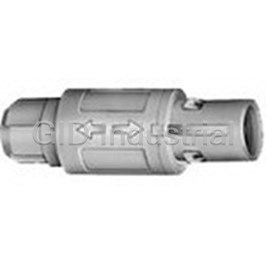
Conn Circular M 26 POS ST Cable Mount 26 Terminal 1 Port CAB.M26.GLA.C52V
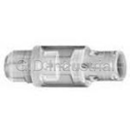
Conn Circular PL 26 POS ST Cable Mount 26Terminal 1Port CAB.M26.SLA.C72GZ
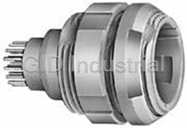
Conn Circular SKT 16 POS Solder ST Panel Mount 16 Terminal 1 Port CKB.M16.GLLG
Conn Circular F 16 POS Solder RA Panel Mount 16 Terminal 1 Port CKB.M16.GLVG
Request a Quote

The quote request has been received
Close

Facing challenges or have inquiries? Feel free to contact us!
Call Us +1-469-283-2440
What they say about us
FANTASTIC RESOURCE
One of our top priorities is maintaining our business with precision, and we are constantly looking for affiliates that can help us achieve our goal. With the aid of GID Industrial, our obsolete product management has never been more efficient. They have been a great resource to our company, and have quickly become a go-to supplier on our list!
Bucher Emhart Glass
EXCELLENT SERVICE
With our strict fundamentals and high expectations, we were surprised when we came across GID Industrial and their competitive pricing. When we approached them with our issue, they were incredibly confident in being able to provide us with a seamless solution at the best price for us. GID Industrial quickly understood our needs and provided us with excellent service, as well as fully tested product to ensure what we received would be the right fit for our company.
Fuji
HARD TO FIND A BETTER PROVIDER
Our company provides services to aid in the manufacture of technological products, such as semiconductors and flat panel displays, and often searching for distributors of obsolete product we require can waste time and money. Finding GID Industrial proved to be a great asset to our company, with cost effective solutions and superior knowledge on all of their materials, it’d be hard to find a better provider of obsolete or hard to find products.
Applied Materials
CONSISTENTLY DELIVERS QUALITY SOLUTIONS
Over the years, the equipment used in our company becomes discontinued, but they’re still of great use to us and our customers. Once these products are no longer available through the manufacturer, finding a reliable, quick supplier is a necessity, and luckily for us, GID Industrial has provided the most trustworthy, quality solutions to our obsolete component needs.
Nidec Vamco
TERRIFIC RESOURCE
This company has been a terrific help to us (I work for Trican Well Service) in sourcing the Micron Ram Memory we needed for our Siemens computers. Great service! And great pricing! I know when the product is shipping and when it will arrive, all the way through the ordering process.
Trican Well Service
GO TO SOURCE
When I can't find an obsolete part, I first call GID and they'll come up with my parts every time. Great customer service and follow up as well. Scott emails me from time to time to touch base and see if we're having trouble finding something.....which is often with our 25 yr old equipment.
ConAgra Foods