

 Manufacturers
LEMO DCF.93.070.4LT
Description
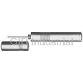
Extractor For Crimp Contacts
DCF.93.070.4LT
Part Number
DCF.93.070.4LT
Price
Request Quote
Manufacturer
LEMO
Lead Time
Request Quote
Category
Tools and Supplies » Assembly Tools
Specifications
Manufacturer
LEMO
Manufacturers Part #
DCF.93.070.4LT
Industry Aliases
DCF.93.070.4LT
Sub-Category
Electronics Assembly Tools
Factory Pack Quantity
1
Datasheet

Extracted Text
M SERIES CONNECTORS RATCHET COUPLING ® ® Introduction This catalogue gives the complete description of LEMO M series connectors. M series connectors are lightweight triple- start ratchet coupling type connectors designed for avionics, aerospace, military, security, motorsport and heavy duty applications. The LEMO manufacturing programme has been extended to almost 40 series divided into 7 product families with specific mating and environmental characteristics. Each series includes a wide variety of plug, socket and coupler models, available in contact configurations adapted to all round cables. Watertight models are also available. Since LEMO connectors are perfectly screened and designed to guarantee very low resistance to shell electrical continuity, they are particularly adapted to applications where electromagnetic compatibility (EMC) is important. Technical Characteristics Materials and Treatments Surface treatment (µm) Shell material code Component Material (Standard) nickel Notes chrome gold I X C I X l Brass (UNS C 38500) 0.3 – – – Outer shell Aluminium alloy (AA 6262A or AA 6023) – 14 5 – 1) l l l Brass (UNS C 38500) 0.3 – – – Conical nut 1) l l Aluminium alloy (AA 6262A or AA 6023) – 14 5 – Earthing crown l l l Bronze (UNS C 54400) or special brass – – – 1.5 l Brass (UNS C 38500) – – 3 – – Coupling nut Aluminium alloy (AA 6262A or AA 6023) – 14 3 – 1) l l Ratchet l l l Special PEEK – l Brass (UNS C 38500) – – 3 – Hexagonal nut l l Aluminium alloy (AA 6262A or AA 6023) – – 5 – Male crimp contact Brass (UNS C 34500) – – – 1.0 – l l l Female crimp contact Bronze (UNS C 54400) – – – 1.5 – l l l Clips l l l Cu-Be or special steel without treatment Insulator l l l PEEK – l Silicone – O-ring ® l l FPM/FKM (Viton ) – ® ® Sealing resin Epoxy (Araldite or Stycast ) – l l l Cable rear seal l l l Fluorosilicone – Spring l l l Stainless steel – Notes: standards for surface treatment are as follows: chrome-plated SAE AMS 2460; nickel-plated SAE AMS QQ N 290 or MIL DTL 32119; gold-plated 1) ISO 27874. anthracite colour. www.lemo.com 1 ® ® Environmental performance Characteristics Value IEC international MIL-spec tests Operating temperature (mated) -55°C/+200°C (HEl model: -20°C/+80°C) Ingress protection index IP 68 (at 2 m, 15Hr) IEC 60529 Fungus Satisfied - by material analysis MIL-STD 810F-508.5 Flammability 60 sec. front and back face EIA-364-104A 1) Fluid contamination Fuels, gasoline, hydraulic oils, solvents, de-icing MIL-STD-810F method 504 2) Sand and dust 6 hr, 55°C, blowing < 150 µm dust MIL-STD 810F-510.4 Lightning strike 10 K amps - 6 times EIA-364-75 3) Altitude-low temp -65°C; 40’000 feet and 400 VAC EIA-364-105A 4) Salt fog Alum. shell (up to 500Hr), Brass shell (1000Hr) IEC 60512-6 test 11f EIA-364-26 Thermal shock 5 cycles: -65°C to +150°C IEC 60512-11-4 EIA-364-32 test condition IV Altitude immersion No moisture on contacts EIA-364-03 Humidity 21 days at 95% IEC 60068-2 EIA-364-31 method IV 1) Note: Connectors immersed at both 70°C and 25°C according to specification. Connectors are then inspected, no visual signs of damage seen. Fuels: Kerosene, JP4, (Nato F40) at 70°C +/- 2°C. Gasoline: ASTM 4814. Hydraulic oils: Mineral oil based MIL-H-5606. Solvents: Isopropanol. De-icing fluids: 25% ethylene glycol. 2) No signs of damage, connectors opened and closed without difficulty. Dust or sand was not inside connector. 3) Wired mated connectors = no voltage breakdown, shell to all contacts (connected together) w/400 VAC after 1 hour at 65° C at 40’000 feet altitude. 4) Corrosion resistance. Inspection: salt deposits shall be removed by gentle wash in running water with light brushing using soft brush. Aluminium Shell (material code: X) max: 48 hours, (material code: I) max: 500 hours. Brass shell (material code: C) over 1000 hours. Electrical performance Characteristics Value IEC international MIL-spec tests 6) 12 10 Insulation resist. (at ambient temp.) > 10 Ω, > 10 Ω (after humidity) IEC 60512-2 test 3a EIA-364-21 Dielectric withstanding volt. (sea level) See table page 25, 26, 27 IEC 60512-2 test 4a EIA-364-20 7) Contact resistance See table below IEC 60512-2 test 2a EIA-364-06 Current rating See insulator configuration page 25, 26, 27 IEC 60512-3 test 5a Shell to shell conductivity < 1.5m Ω IEC 60512-2-6 EIA-364-83 Shielding effectiveness, low frequency ≥ 80 dB up to 1GHz EIA-364-66 Shielding effectiveness, high frequency ≥ 70 dB (3GHz), ≥ 58 dB (6GHz), ≥ 40 dB (10GHz) EIA-364-66 6) Note: After humidity test: 21 days at 95% RH according to IEC 60068-2. Insulation resistance measured between the contacts and contact/shell. 7) Contact resistance Value IEC 60512-2 test 2a ø A 0.5 0.7 0.9 1.3 (mm) ≤ 8.7 ≤ 6.1 ≤ 4.8 ≤ 3.6 mΩ 7) Notes: after 5000 mating cycles and the salt spray test according to IEC 60512-6 test 11 f. 2 www.lemo.com ® ® Mechanical performance Characteristics Value IEC international MIL-spec tests Endurance 3000 cycles IEC 60512-5 test 9a EIA-364-09 Gunfire vibration 25 to 2000 Hz, 3 axis (Apache helicopter) MIL-STD-810F method 519.5 8) Vibration-Sine 30 g, 3 axis, 12 hr MIL-STD-202 method 204-G Vibration-Random 50-2000 Hz, 37.8 g rms-3 axes; 4h amb IEC 60512-6-4 EIA-364-28 test cond. V letter I Shock 300 g - 3 msec IEC 60512-6-3 EIA-364-27 condition D Acceleration 50 g acceleration MIL-STD-1344 - 2011-1, A Contact retention > 22 N (ø 0.7mm), > 30N (ø 0.9 mm) IEC 60512-8 test 15a Torque See table below 8) Note: Amplitude: 30G. Frequency: 10 to 2000 Hz. Time per axis: 4 hours (X, Y, Z). No signal discontinuity above 1 µs. Coupling torque Coupling torque Coupling torque Coupling torque Series Series tightning (N.cm) untightning (N.cm) tightning (N.cm) untightning (N.cm) MM 8 4 TM 26 30 0M 4 5 4M 26 25 9) 1M 10 11 LM 48 43 9) 20 14 91 54 2M 5M 3M 34 29 9) Note: Higher contact density = larger torque force. www.lemo.com 3 ® ® M Series The M Series connector offers a new innovative design for avionics, aerospace, military, security, motorsport and heavy duty applications. Made of high-strength aluminium, this connector is one of the lightest and most compact of the LEMO product line. A one-grip ratchet screw system enables quick and secure coupling of the connectors. The arctic grip makes it easy to manipulate the connector while wearing gloves or when the connector is located in a difficult to access area. Features – Ratchet-coupling mechanism – Quick mating: less than 3/4 turn to seat – Compact design for space savings – Lightweight – Oil and fuel resistant – High vibration and shock resistance – 360° screening for full EMC shielding – Sealed to IP68 when mated – Colour coding / keying – Reverse gender configuration – Scoop proof – Pin configuration from 2 to 114 contacts – Threaded for MIL-DTL-38999L backshell Metal housing models (page 6) Straight plugs Fixed sockets Free sockets FA FG FM EG PM PV PB FA FG FM EG PM PV PB FA FG FM EC PM PV PB FW FX EC PH FW FX PE PF ED PH PF FW FX ED PE PH USB models (page 24) Watertight Straight plugs Fixed sockets Fixed socket model (unmated) FG FM EG EG HE Straight plugs Fixed sockets Free sockets Fibre optic models (page 21) FM EG PM FG ED PH 4 www.lemo.com ® ® Part Numbering System F M N 1 M 3 0 5 X L C Plug F G N 1 M 3 0 5 X L C M Free socket P M N 1 M 3 0 5 X L M T H E N 1 M 3 0 5 X L N Fixed socket P Variant: T = Mold stop P = Potted M = MIL-DTL-38999L shell thread Contact: (page 28) Insulator: L = PEEK (multipole page 25) R = PEEK (mixed multipole p. 27) Model: (page 6) Housing: Alignment key: (page 24) C = Chrome-plated brass 1) X = Nickel-plated aluminium alloy TM Series: (page 6) I = NiCorAI Nickel fluorocarbon polymer 2) Insert configuration: (page 25) aluminium alloy FMN.1M.305.XLC = straight plug with key (N), 1M series, multipole type with 5 contacts, outer shell in anthracite nickel-plated aluminium alloy, PEEK insulator, male crimp contacts. FGN.1M.305.XLCM = straight plug with key (N), arctic grip, 1M series, multipole type with 5 contacts, outer shell in anthracite nickel- plated aluminium alloy, PEEK insulator, male crimp contacts and with MIL-DTL-38999L thread for additional backshell (not supplied). PMN.1M.305.XLMT = free socket with key (N), 1M series, multipole type with 5 contacts, outer shell in anthracite nickel-plated aluminium alloy, PEEK insulator, female crimp contacts and mold stop. HEN.1M.305.XLNP = fixed socket, nut fixing, with key (N), 1M series, multipole type with 5 contacts, outer shell in anthracite nickel-plated aluminium alloy, PEEK insulator, female print contacts, watertight. 1) 2) Note: anthracite colour / 48 hours salt fog resistance. anthracite colour / 500 hours salt fog resistance RoHS 2/REACH. Part Section Showing Internal Components 5 4 6 3 2 1 1 3 Fixed socket 2 7 5 6 4 Straight plug 1 outer shell 1 outer shell 2 o-ring 2 insulator 3 3 male contact hexagonal nut 4 rear seal 4 insulator 5 5 female contact tightening screw 6 6 earthing crown ratchet mechanism 7 spring www.lemo.com 5 ® ® Metal housing models FMl Straight plug, key (N) or keys (P, R, S, T, U, V, W and X) with knurled grip Reference Dimensions (mm) Model Series A B C D Ls Lr P X FMl MM 11.1 6.4 10.7 5.6 21.3 21.3 5.5 5.8 FMl 0M 13.1 8.8 12.7 8.0 24.1 24.1 3.9 6.7 FMl 1M 14.6 10.5 14.2 9.7 24.1 24.1 3.9 6.7 Ls/Lr X P FMl 2M 17.6 14.0 17.2 13.0 24.5 24.5 3.9 7.1 FMl 3M 19.6 16.0 19.2 15.0 24.5 24.5 3.9 7.1 FMl TM 22.5 17.9 22.0 16.7 28.6 28.6 3.4 7.6 FMl 4M 25.0 20.7 24.5 19.5 28.6 28.6 3.4 7.6 FMl LM 28.5 23.9 28.0 22.7 28.6 28.6 3.4 7.6 FMl 5M 34.0 29.7 33.5 28.5 28.6 28.6 3.4 7.6 Part number example: FMN.1M.305.XLC Note: Ls = standard gender, Lr = reverse gender FMl Straight plug, key (N) or keys (P, R, S, T, U, V, W and X) with knurled grip and mold stop Reference Dimensions (mm) Model Series A B C D F Ls Lr M P X FMl MM 11.1 6.4 10.7 5.6 7.8 24.3 24.3 8.8 5.5 5.8 13.1 8.8 12.7 8.0 10.7 27.1 27.1 9.7 3.9 6.7 FMl 0M Ls/Lr M P FMl 1M 14.6 10.5 14.2 9.7 12.4 27.1 27.1 9.7 3.9 6.7 FMl 2M 17.6 14.0 17.2 13.0 15.5 27.5 27.5 10.1 3.9 7.1 FMl 3M 19.6 16.0 19.2 15.0 17.5 27.5 27.5 10.1 3.9 7.1 FMl TM 22.5 17.9 22.0 16.7 19.8 31.6 31.6 10.6 3.4 7.6 X 1.5 25.0 20.7 24.5 19.5 22.6 31.6 31.6 10.6 3.4 7.6 FMl 4M FMl LM 28.5 23.9 28.0 22.7 25.8 31.6 31.6 10.6 3.4 7.6 FMl 5M 34.0 29.7 33.5 28.5 31.4 31.6 31.6 10.6 3.4 7.6 Part number example: FMN.1M.305.XLCT Note: Ls = standard gender, Lr = reverse gender FMl Straight plug, key (N) or keys (P, R, S, T, U, V, W and X) with knurled grip and MIL-DTL-38999L shell thread Reference Dimensions (mm) 1) Model Series A C e Ls Lr P Code FMl 1M 14.6 14.2 M12x1.0 26.4 26.4 3.9 A FMl 2M 17.6 17.2 M15x1.0 26.4 26.4 3.9 B Ls/Lr 9 P FMl 3M 19.6 19.2 M18x1.0 26.4 26.4 3.9 C FMl TM 22.5 22.0 M18x1.0 30.0 30.0 3.4 C FMl 4M 25.0 24.5 M22x1.0 30.0 30.0 3.4 D FMl LM 28.5 28.0 M25x1.0 30.0 30.0 3.4 E FMl 5M 34.0 33.5 M31x1.0 30.0 30.0 3.4 G Part number example: FMN.1M.305.XLCM 1) Note: Ls = standard gender, Lr = reverse gender. MIL-DTL-38999L shell size code (backshell not supplied). 6 www.lemo.com ø F ø B ø B e ø D ø D ø C ø C ø A ø C ø A ø A ® ® FGl Straight plug, key (N) or keys (P, R, S, T, U, V, W and X) with arctic grip Reference Dimensions (mm) Model Series A B C D Ls Lr P X 12.0 6.4 10.7 5.6 21.3 21.3 5.5 5.8 FGl MM FGl 0M 14.4 8.8 12.7 8.0 24.1 24.1 3.9 6.7 Ls/Lr FGl 1M 15.9 10.5 14.2 9.7 24.1 24.1 3.9 6.7 P 18.9 14.0 17.2 13.0 24.5 24.5 3.9 7.1 FGl 2M FGl 3M 20.9 16.0 19.2 15.0 24.5 24.5 3.9 7.1 23.4 17.9 22.0 16.7 28.6 28.6 3.4 7.6 FGl TM X FGl 4M 25.9 20.7 24.5 19.5 28.6 28.6 3.4 7.6 FGl LM 29.4 23.9 28.0 22.7 28.6 28.6 3.4 7.6 34.9 29.7 33.5 28.5 28.6 28.6 3.4 7.6 FGl 5M Part number example: FGN.1M.305.XLC Note: Ls = standard gender, Lr = reverse gender FGl Straight plug, key (N) or keys (P, R, S, T, U, V, W and X) with arctic grip and mold stop Reference Dimensions (mm) Model Series A B C D F Ls Lr M P X FGl MM 12.0 6.4 10.7 5.6 7.8 24.3 24.3 8.8 5.5 5.8 FGl 0M 14.4 8.8 12.7 8.0 10.7 27.1 27.1 9.7 3.9 6.7 Ls/Lr M P FGl 1M 15.9 10.5 14.2 9.7 12.4 27.1 27.1 9.7 3.9 6.7 FGl 2M 18.9 14.0 17.2 13.0 15.5 27.5 27.5 10.1 3.9 7.1 FGl 3M 20.9 16.0 19.2 15.0 17.5 27.5 27.5 10.1 3.9 7.1 FGl TM 23.4 17.9 22.0 16.7 19.8 31.6 31.6 10.6 3.4 7.6 X 1.5 FGl 4M 25.9 20.7 24.5 19.5 22.6 31.6 31.6 10.6 3.4 7.6 FGl LM 29.4 23.9 28.0 22.7 25.8 31.6 31.6 10.6 3.4 7.6 FGl 5M 34.9 29.7 33.5 28.5 31.4 31.6 31.6 10.6 3.4 7.6 Part number example: FGN.1M.305.XLCT Note: Ls = standard gender, Lr = reverse gender FGl Straight plug, key (N) or keys (P, R, S, T, U, V, W and X) with arctic grip and MIL-DTL-38999L shell thread Dimensions (mm) Reference 1) Model Series A C e Ls Lr P Code 15.9 14.2 M12x1.0 26.4 26.4 3.9 A FGl 1M FGl 2M 18.9 17.2 M15x1.0 26.4 26.4 3.9 B Ls/Lr 9 P FGl 3M 20.9 19.2 M18x1.0 26.4 26.4 3.9 C FGl TM 23.4 22.0 M18x1.0 30.0 30.0 3.4 C FGl 4M 25.9 24.5 M22x1.0 30.0 30.0 3.4 D 29.4 28.0 M25x1.0 30.0 30.0 3.4 E FGl LM FGl 5M 34.9 33.5 M31x1.0 30.0 30.0 3.4 G Part number example: FGN.1M.305.XLCM 1) Note: Ls = standard gender, Lr = reverse gender. MIL-DTL-38999L shell size code (backshell not supplied). www.lemo.com 7 ø F ø B ø B e ø D ø D ø C ø C ø A ø C ø A ø A ® ® FXl Straight plug with square flange, key (N) or keys (P, R, S, T, U, V, W and X) with knurled grip Reference Dimensions (mm) Model Series A A1 B C D E G H K Ls Lr N V FXl MM 21.5 11.1 6.4 10.7 5.6 9.5 17.0 12.0 1.5 26.1 26.1 17.0 2.7 FXl 0M 26.9 13.1 8.8 12.7 8.0 12.2 18.9 15.1 1.5 29.1 29.1 20.6 2.7 FXl 1M 31.4 14.6 10.5 14.2 9.7 13.7 18.9 18.3 1.5 29.1 29.1 23.8 3.3 FXl 2M 34.6 17.6 14.0 17.2 13.0 16.7 18.9 20.6 1.5 29.5 29.5 26.1 3.3 Ls/Lr FXl 3M 34.6 19.6 16.0 19.2 15.0 18.7 18.9 20.6 1.5 29.5 29.5 26.1 3.3 X ø A 1.5 FXl TM 38.0 22.5 17.9 22.0 16.7 21.5 22.5 23.0 2.0 34.8 34.8 28.5 3.3 N P FXl 4M 40.3 25.0 20.7 24.5 19.5 24.0 22.5 24.6 2.0 34.8 34.8 30.1 3.3 FXl LM 43.7 28.5 23.9 28.0 22.7 27.5 22.5 27.0 2.0 34.8 34.8 32.5 3.3 FXl 5M 47.0 34.0 29.7 33.5 28.5 33.0 22.5 29.4 2.0 34.8 34.8 37.0 3.3 ø V Part number example: FXN.1M.305.XLC H G K Note: The dimensions «P» and «X» are the same as the FMl models. Ls = standard gender, Lr = reverse gender. FXl Straight plug with square flange, key (N) or keys (P, R, S, T, U, V, W and X) with knurled grip and mold stop Reference Dimensions (mm) Model Series A A1 B C D E G H K Ls Lr N V FXl MM 21.5 11.1 6.4 10.7 5.6 9.5 17.0 12.0 1.5 29.1 29.1 17.0 2.7 FXl 0M 26.9 13.1 8.8 12.7 8.0 12.2 18.9 15.1 1.5 32.1 32.1 20.6 2.7 FXl 1M 31.4 14.6 10.5 14.2 9.7 13.7 18.9 18.3 1.5 32.1 32.1 23.8 3.3 FXl 2M 34.6 17.6 14.0 17.2 13.0 16.7 18.9 20.6 1.5 32.5 32.5 26.1 3.3 FXl 3M 34.6 19.6 16.0 19.2 15.0 18.7 18.9 20.6 1.5 32.5 32.5 26.1 3.3 Ls/Lr ø A 1.5 N M P FXl TM 38.0 22.5 17.9 22.0 16.7 21.5 22.5 23.0 2.0 37.8 37.8 28.5 3.3 FXl 4M 40.3 25.0 20.7 24.5 19.5 24.0 22.5 24.6 2.0 37.8 37.8 30.1 3.3 FXl LM 43.7 28.5 23.9 28.0 22.7 27.5 22.5 27.0 2.0 37.8 37.8 32.5 3.3 FXl 5M 47.0 34.0 29.7 33.5 28.5 33.0 22.5 29.4 2.0 37.8 37.8 37.0 3.3 X ø V 1.5 H G Part number example: FXN.1M.305.XLCT K Note: The dimensions «F», «M», «P» and «X» are the same as the FMl models. Ls = standard gender, Lr = reverse gender. FXl Straight plug with square flange, key (N) or keys (P, R, S, T, U, V, W and X) with knurled grip and MIL-DTL-38999L shell thread Reference Dimensions (mm) 1) Model Series A A1 C e E G H K Ls Lr Code FXl 1M 31.4 14.6 14.2 M12x1.0 13.7 18.9 18.3 1.5 31.4 31.4 A FXl 2M 34.6 17.6 17.2 M15x1.0 16.7 18.9 20.6 1.5 31.4 31.4 B FXl 3M 34.6 19.6 19.2 M18x1.0 18.7 18.9 20.6 1.5 31.4 31.4 C 38.0 22.5 22.0 M18x1.0 21.5 22.5 23.0 2.0 36.2 36.2 C FXl TM Ls/Lr ø A 1.5 N 9 P FXl 4M 40.3 25.0 24.5 M22x1.0 24.0 22.5 24.6 2.0 36.2 36.2 D FXl LM 43.7 28.5 28.0 M25x1.0 27.5 22.5 27.0 2.0 36.2 36.2 E FXl 5M 47.0 34.0 33.5 M31x1.0 33.0 22.5 29.4 2.0 36.2 36.2 F Part number example: FXN.1M.305.XLCM ø V H G Note: The dimensions «N» and «V» are the same as the FXl models and the dimen- K sion «P» is the same as the FMl models. Ls = standard gender, Lr = reverse gender. 1) MIL-DTL-38999L shell size code (backshell not supplied). 8 www.lemo.com ø E ø F ø E ø E ø B ø B e ø D ø D ø C ø C ø A1 ø C ø A1 ø A1 ® ® FWl Straight plug with square flange, key (N) or keys (P, R, S, T, U, V, W and X) with arctic grip Reference Dimensions (mm) Model Series A A1 B C D E G H K Ls Lr N V FWl MM 21.5 12.0 6.4 10.7 5.6 9.5 17.0 12.0 1.5 26.1 26.1 17.0 2.7 FWl 0M 26.9 14.4 8.8 12.7 8.0 12.2 18.9 15.1 1.5 29.1 29.1 20.6 2.7 FWl 1M 31.4 15.9 10.5 14.2 9.7 13.7 18.9 18.3 1.5 29.1 29.1 23.8 3.3 FWl 2M 34.6 18.9 14.0 17.2 13.0 16.7 18.9 20.6 1.5 29.5 29.5 26.1 3.3 Ls/Lr FWl 3M 34.6 20.9 16.0 19.2 15.0 18.7 18.9 20.6 1.5 29.5 29.5 26.1 3.3 X 1.5 ø A FWl TM 38.0 23.4 17.9 22.0 16.7 21.5 22.5 23.0 2.0 34.8 34.8 28.5 3.3 N P FWl 4M 40.3 25.9 20.7 24.5 19.5 24.0 22.5 24.6 2.0 34.8 34.8 30.1 3.3 FWl LM 43.7 29.4 23.9 28.0 22.7 27.5 22.5 27.0 2.0 34.8 34.8 32.5 3.3 FWl 5M 47.0 34.9 29.7 33.5 28.5 33.0 22.5 29.4 2.0 34.8 34.8 37.0 3.3 Part number example: FWN.1M.305.XLC ø V H G K Note: The dimensions «P» and «X» are the same as the FMl models. Ls = standard gender, Lr = reverse gender. FWl Straight plug with square flange, key (N) or keys (P, R, S, T, U, V, W and X) with arctic grip and mold stop Reference Dimensions (mm) Model Series A A1 B C D E G H K Ls Lr N V FWl MM 21.5 12.0 6.4 10.7 5.6 9.5 17.0 12.0 1.5 29.1 29.1 17.0 2.7 26.9 14.4 8.8 12.7 8.0 12.2 18.9 15.1 1.5 32.1 32.1 20.6 2.7 FWl 0M FWl 1M 31.4 15.9 10.5 14.2 9.7 13.7 18.9 18.3 1.5 32.1 32.1 23.8 3.3 34.6 18.9 14.0 17.2 13.0 16.7 18.9 20.6 1.5 32.5 32.5 26.1 3.3 FWl 2M 34.6 20.9 16.0 19.2 15.0 18.7 18.9 20.6 1.5 32.5 32.5 26.1 3.3 FWl 3M Ls/Lr 1.5 ø A N M P FWl TM 38.0 23.4 17.9 22.0 16.7 21.5 22.5 23.0 2.0 37.8 37.8 28.5 3.3 40.3 25.9 20.7 24.5 19.5 24.0 22.5 24.6 2.0 37.8 37.8 30.1 3.3 FWl 4M FWl LM 43.7 29.4 23.9 28.0 22.7 27.5 22.5 27.0 2.0 37.8 37.8 32.5 3.3 47.0 34.9 29.7 33.5 28.5 33.0 22.5 29.4 2.0 37.8 37.8 37.0 3.3 FWl 5M X ø V 1.5 H G Part number example: FWN.1M.305.XLCT K Note: The dimensions «F», «M», «P» and «X» are the same as the FMl models. Ls = standard gender, Lr = reverse gender. FWl Straight plug with square flange, key (N) or keys (P, R, S, T, U, V, W and X) with arctic grip and MIL-DTL-38999L shell thread Reference Dimensions (mm) 1) Model Series A A1 C e E G H K Ls Lr Code FWl 1M 31.4 15.9 14.2 M12x1.0 13.7 18.9 18.3 1.5 31.4 31.4 A 34.6 18.9 17.2 M15x1.0 16.7 18.9 20.6 1.5 31.4 31.4 B FWl 2M FWl 3M 34.6 20.9 19.2 M18x1.0 18.7 18.9 20.6 1.5 31.4 31.4 C FWl TM 38.0 23.4 22.0 M18x1.0 21.5 22.5 23.0 2.0 36.2 36.2 C Ls/Lr ø A 1.5 N 9 P FWl 4M 40.3 25.9 24.5 M22x1.0 24.0 22.5 24.6 2.0 36.2 36.2 D FWl LM 43.7 29.4 28.0 M25x1.0 27.5 22.5 27.0 2.0 36.2 36.2 E 47.0 34.9 33.5 M31x1.0 33.0 22.5 29.4 2.0 36.2 36.2 F FWl 5M Part number example: FWN.1M.305.XLCM ø V H G Note: The dimensions «N» and «V» are the same as the FWl models and the dimen- K sion «P» is the same as the FMl models. Ls = standard gender, Lr = reverse gender. 1) MIL-DTL-38999L shell size code (backshell not supplied). www.lemo.com 9 ø E ø F ø E ø B ø E ø B e ø D ø D ø C ø C ø C ø A1 ø A1 ø A1 ® ® FAl Straight plug with square flange, non-coupling, key (N) or keys (P, R, S, T, U, V, W and X) Reference Dimensions (mm) Model Series A B C D E G H K Ls Lr N P V FAl MM 21.5 6.4 10.7 5.6 9.5 17.0 12.0 1.5 26.1 26.1 17.0 5.5 2.7 FAl 0M 26.9 8.8 12.7 8.0 12.2 18.9 15.1 1.5 29.1 29.1 20.6 3.9 2.7 FAl 1M 31.4 10.5 14.2 9.7 13.7 18.9 18.3 1.5 29.1 29.1 23.8 3.9 3.3 FAl 2M 34.6 14.0 17.2 13.0 16.7 18.9 20.6 1.5 29.5 29.5 26.1 3.9 3.3 FAl 3M 34.6 16.0 19.2 15.0 18.7 18.9 20.6 1.5 29.5 29.5 26.1 3.9 3.3 Ls/Lr ø A X P N FAl TM 38.0 17.9 22.0 16.7 21.5 22.5 23.0 2.0 34.8 34.8 28.5 3.4 3.3 FAl 4M 40.3 20.7 24.5 19.5 24.0 22.5 24.6 2.0 34.8 34.8 30.1 3.4 3.3 FAl LM 43.7 23.9 28.0 22.7 27.5 22.5 27.0 2.0 34.8 34.8 32.5 3.4 3.3 FAl 5M 47.0 29.7 33.5 28.5 33.0 22.5 29.4 2.0 34.8 34.8 37.0 3.4 3.3 ø V H G Part number example: FAN.1M.305.XLC K Note: The dimension «X» is the same as the FMl models. Ls = standard gender, Lr = reverse gender. FAl Straight plug with square flange, non-coupling, key (N) or keys (P, R, S, T, U, V, W and X) with mold stop Reference Dimensions (mm) Model Series A B C D E G H K Ls Lr N P V FAl MM 21.5 6.4 10.7 5.6 9.5 17.0 12.0 1.5 29.1 29.1 17.0 5.5 2.7 FAl 0M 26.9 8.8 12.7 8.0 12.2 18.9 15.1 1.5 32.1 32.1 20.6 3.9 2.7 FAl 1M 31.4 10.5 14.2 9.7 13.7 18.9 18.3 1.5 32.1 32.1 23.8 3.9 3.3 FAl 2M 34.6 14.0 17.2 13.0 16.7 18.9 20.6 1.5 32.5 32.5 26.1 3.9 3.3 FAl 3M 34.6 16.0 19.2 15.0 18.7 18.9 20.6 1.5 32.5 32.5 26.1 3.9 3.3 Ls/Lr ø A N M P FAl TM 38.0 17.9 22.0 16.7 21.5 22.5 23.0 2.0 37.8 37.8 28.5 3.4 3.3 FAl 4M 40.3 20.7 24.5 19.5 24.0 22.5 24.6 2.0 37.8 37.8 30.1 3.4 3.3 FAl LM 43.7 23.9 28.0 22.7 27.5 22.5 27.0 2.0 37.8 37.8 32.5 3.4 3.3 FAl 5M 47.0 29.7 33.5 28.5 33.0 22.5 29.4 2.0 37.8 37.8 37.0 3.4 3.3 X ø V 1.5 H G Part number example: FAN.1M.305.XLC K Note: The dimension «X» is the same as the FMl models. Ls = standard gender, Lr = reverse gender. FAl Straight plug with square flange, non-coupling, key (N) or keys (P, R, S, T, U, V, W and X) with MIL-DTL-38999L shell thread Reference Dimensions (mm) 1) Model Series A C e E G H K Ls Lr N Code FAl 1M 31.4 14.2 M12x1.0 13.7 18.9 18.3 1.5 31.4 31.4 23.8 A FAl 2M 34.6 17.2 M15x1.0 16.7 18.9 20.6 1.5 31.4 31.4 26.1 B FAl 3M 34.6 19.2 M18x1.0 18.7 18.9 20.6 1.5 31.4 31.4 26.1 C 38.0 22.0 M18x1.0 21.5 22.5 23.0 2.0 36.2 36.2 28.5 C FAl TM Ls/Lr ø A N 9 P FAl 4M 40.3 24.5 M22x1.0 24.0 22.5 24.6 2.0 36.2 36.2 30.1 D FAl LM 43.7 28.0 M25x1.0 27.5 22.5 27.0 2.0 36.2 36.2 32.5 E FAl 5M 47.0 33.5 M31x1.0 33.0 22.5 29.4 2.0 36.2 36.2 37.0 F Part number example: FAN.1M.305.XLCM ø V Note: The dimensions «P» and «V» are the same as the FAl models. H G 1) K Ls = standard gender, Lr = reverse gender. MIL-DTL-38999L shell size code (backshell not supplied). 10 www.lemo.com ø E ø F ø E ø E ø B ø B e ø D ø D ø C ø C ø C ® ® EGl Fixed socket, nut fixing, key (N) or keys (P, R, S, T, U, V, W and X) Reference Dimensions (mm) Model Series C D e E Ls Lr P S1 S2 EGl MM 10.7 5.2 M7x0.5 4.5 15.0 15.0 3.7 6.3 9.0 EGl 0M 12.7 6.8 M9x0.6 5.0 18.3 18.3 5.3 8.2 11.0 EGl 1M 14.2 6.8 M11x1.0 4.5 18.3 18.3 5.3 9.5 13.0 EGl 2M 17.2 6.8 M14x1.0 4.5 18.3 18.3 5.3 12.5 17.0 EGl 3M 19.2 6.8 M16x1.0 4.0 18.3 18.3 5.3 14.5 19.0 EGl TM 22.0 9.4 M18x1.0 4.0 20.0 21.9 7.9 16.5 22.0 Ls/Lr S 1 P EGl 4M 24.5 9.4 M21x1.0 4.0 20.0 21.9 7.9 19.5 25.0 EGl LM 28.0 9.4 M24x1.0 4.0 20.0 21.9 7.9 22.5 30.0 EGl 5M 33.5 9.4 M30x1.0 4.0 20.0 21.9 7.9 28.5 36.0 D Part number example: EGN.1M.305.XLM S 2 E maxi Panel cut-out (page 36). Note: Ls = standard gender, Lr = reverse gender EGl Fixed socket, nut fixing, key (N) or keys (P, R, S, T, U, V, W and X) for printed circuit Dimensions (mm) Reference Model Series C D e E G Ls Lr P S1 S2 EGl MM 10.7 5.2 M7x0.5 4.5 13.8 15.0 15.0 3.7 6.3 9.0 EGl 0M 12.7 6.8 M9x0.6 5.0 16.8 18.3 18.3 5.3 8.2 11.0 EGl 1M 14.2 6.8 M11x1.0 4.5 16.8 18.3 18.3 5.3 9.5 13.0 EGl 2M 17.2 6.8 M14x1.0 4.5 16.8 18.3 18.3 5.3 12.5 17.0 EGl 3M 19.2 6.8 M16x1.0 4.0 16.8 18.3 18.3 5.3 14.5 19.0 Ls/Lr EGl TM 22.0 9.4 M18x1.0 4.0 18.9 20.0 21.9 7.9 16.5 22.0 G S 1 S 2 EGl 4M 24.5 9.4 M21x1.0 4.0 18.9 20.0 21.9 7.9 19.5 25.0 P EGl LM 28.0 9.4 M24x1.0 4.0 18.9 20.0 21.9 7.9 22.5 30.0 EGl 5M 33.5 9.4 M30x1.0 4.0 18.9 20.0 21.9 7.9 28.5 36.0 Part number example: EGN.1M.305.XLN 4.5 D E maxi 5.4 Panel cut-out (page 36). PCB drilling pattern (page 37). Note: Ls = standard gender, Lr = reverse gender www.lemo.com 11 e e ø C ø C ® ® ECl Fixed socket with two nuts, key (N) or keys (P, R, S, T, U, V, W and X) Reference Dimensions (mm) Model Series A B C E e G Ls Lr P S1 S2 S3 ECl MM 14 2.85 13.5 5.0 M10x0.50 13.8 15.0 15.0 3.7 9.0 11.0 12.0 ECl 0M 17 4.72 18.2 5.0 M13x0.75 16.8 18.3 18.3 5.3 11.5 14.0 16.0 ECl 1M 18 5.95 19.2 5.0 M14x1.00 16.8 18.3 18.3 5.3 12.5 16.0 17.0 ECl 2M 21 8.95 21.5 4.0 M17x1.00 16.8 18.3 18.3 5.3 15.5 18.0 19.0 ECl 3M 23 10.95 25.0 4.0 M19x1.00 16.8 18.3 18.3 5.3 17.5 20.0 22.0 Ls/Lr ECl TM 27 12.30 28.0 2.5 M22x1.00 18.9 20.0 21.9 7.9 20.5 23.0 25.0 S 3 S 1 P ECl 4M 29 13.95 34.0 2.5 M24x1.00 18.9 20.0 21.9 7.9 22.5 25.0 30.0 ECl LM 33 17.95 36.0 2.5 M28x1.00 18.9 20.0 21.9 7.9 26.5 29.0 32.0 ECl 5M 38 22.90 41.0 2.5 M33x1.00 18.9 20.0 21.9 7.9 31.5 34.0 37.0 Part number example: ECN.1M.305.XLM E maxi S 2 G Panel cut-out (page 36). Note: Ls = standard gender, Lr = reverse gender. This model is not IP68 (no panel sealing). ECl Fixed socket with two nuts, key (N) or keys (P, R, S, T, U, V, W and X) for printed circuit Reference Dimensions (mm) Model Series A B C E e G Ls Lr P S1 S2 S3 ECl MM 14 2.85 13.5 5.0 M10x0.50 13.8 15.0 15.0 3.7 9.0 11.0 12.0 ECl 0M 17 4.72 18.2 5.0 M13x0.75 16.8 18.3 18.3 5.3 11.5 14.0 16.0 ECl 1M 18 5.95 19.2 5.0 M14x1.00 16.8 18.3 18.3 5.3 12.5 16.0 17.0 ECl 2M 21 8.95 21.5 4.0 M17x1.00 16.8 18.3 18.3 5.3 15.5 18.0 19.0 ECl 3M 23 10.95 25.0 4.0 M19x1.00 16.8 18.3 18.3 5.3 17.5 20.0 22.0 S 3 Ls/Lr ECl TM 27 12.30 28.0 2.5 M22x1.00 18.9 20.0 21.9 7.9 20.5 23.0 25.0 S 1 5.4 P ECl 4M 29 13.95 34.0 2.5 M24x1.00 18.9 20.0 21.9 7.9 22.5 25.0 30.0 ECl LM 33 17.95 36.0 2.5 M28x1.00 18.9 20.0 21.9 7.9 26.5 29.0 32.0 ECl 5M 38 22.90 41.0 2.5 M33x1.00 18.9 20.0 21.9 7.9 31.5 34.0 37.0 4.5 E maxi S 2 Part number example: ECN.1M.305.XLN G Panel cut-out (page 36). PCB drilling pattern (page 37). Note: Ls = standard gender, Lr = reverse gender. This model is not IP68 (no panel sealing). 12 www.lemo.com ø C ø C ø B ø B e e ø A ø A ® ® EDl Fixed socket with square flange, key (N) or keys (P, R, S, T, U, V, W and X) Reference Dimensions (mm) Model Series A B C G H K Ls Lr N P V EDl MM 18.6 4.70 10.7 12.3 9.5 1.5 17.0 17.0 14.5 3.7 2.7 EDl 0M 20.6 4.72 12.7 12.8 11.0 1.5 18.3 18.3 16.0 5.3 2.7 EDl 1M 23.8 5.95 14.2 12.8 12.9 1.5 18.3 18.3 18.4 5.3 3.3 EDl 2M 26.9 8.95 17.2 12.8 15.1 1.5 18.3 18.3 20.6 5.3 3.3 EDl 3M 29.0 10.95 19.2 12.8 16.6 1.5 18.3 18.3 22.1 5.3 3.3 Ls/Lr EDl TM 31.4 12.30 22.0 14.5 18.3 2.0 20.0 21.9 23.8 7.9 3.3 K ø A N P EDl 4M 34.6 13.95 24.5 14.5 20.6 2.0 20.0 21.9 26.1 7.9 3.3 EDl LM 38.0 17.95 28.0 14.5 23.0 2.0 20.0 21.9 28.5 7.9 3.3 EDl 5M 43.7 22.90 33.5 14.5 27.0 2.0 20.0 21.9 32.5 7.9 3.3 Part number example: EDN.1M.305.XLM ø V H G Panel cut-out (page 36). Note: Ls = standard gender, Lr = reverse gender EDl Fixed socket with square flange, key (N) or keys (P, R, S, T, U, V, W and X) for printed circuit Reference Dimensions (mm) Model Series A B C G H K Ls Lr N P V EDl MM 18.6 4.70 10.7 12.3 9.5 1.5 17.0 17.0 14.5 3.7 2.7 EDl 0M 20.6 4.72 12.7 12.8 11.0 1.5 18.3 18.3 16.0 5.3 2.7 EDl 1M 23.8 5.95 14.2 12.8 12.9 1.5 18.3 18.3 18.4 5.3 3.3 EDl 2M 26.9 8.95 17.2 12.8 15.1 1.5 18.3 18.3 20.6 5.3 3.3 EDl 3M 29.0 10.95 19.2 12.8 16.6 1.5 18.3 18.3 22.1 5.3 3.3 Ls/Lr EDl TM 31.4 12.30 22.0 14.5 18.3 2.0 20.0 21.9 23.8 7.9 3.3 ø A K N P 5.4 EDl 4M 34.6 13.95 24.5 14.5 20.6 2.0 20.0 21.9 26.1 7.9 3.3 EDl LM 38.0 17.95 28.0 14.5 23.0 2.0 20.0 21.9 28.5 7.9 3.3 EDl 5M 43.7 22.90 33.5 14.5 27.0 2.0 20.0 21.9 32.5 7.9 3.3 4.5 Part number example: EDN.1M.305.XLN ø V G H Panel cut-out (page 36). PCB drilling pattern (page 37). Note: Ls = standard gender, Lr = reverse gender www.lemo.com 13 ø B ø B ø C ø C ® ® PEl Fixed socket, nut fixing, key (N) or keys (P, R, S, T, U, V, W and X) with mold stop (back panel mounting) Reference Dimensions (mm) Model Series A B C D E e Ls Lr M P R S1 S2 PEl MM 14 6.4 13.8 5.6 4.0 M10x0.50 21.4 21.4 8.8 3.7 10.5 9.0 11 PEl 0M 17 8.8 16.8 8.0 5.0 M13x0.75 25.6 25.6 9.7 5.3 13.8 11.5 14 PEl 1M 18 10.5 17.8 9.7 5.0 M14x1.00 25.6 25.6 9.7 5.3 13.8 12.5 16 PEl 2M 21 14.0 20.8 13.0 5.0 M17x1.00 26.0 26.0 10.1 5.3 13.8 15.5 18 PEl 3M 23 16.0 22.8 15.0 5.0 M19x1.00 26.0 26.0 10.1 5.3 13.8 17.5 20 Ls/Lr PEl TM 27 17.9 25.8 16.7 4.0 M22x1.00 29.5 30.1 10.6 7.9 16.9 20.5 23 M S 1 P PEl 4M 29 20.7 27.8 19.5 4.0 M24x1.00 29.5 30.1 10.6 7.9 16.9 22.5 25 PEl LM 33 23.9 31.8 22.7 4.0 M28x1.00 29.5 30.1 10.6 7.9 16.9 26.5 29 PEl 5M 38 29.7 36.8 28.5 4.0 M33x1.00 29.5 30.1 10.6 7.9 16.9 31.5 34 S 2 E maxi Part number example: PEN.1M.305.XLMT X R Panel cut-out (page 36). 1.5 Note: this model is only available with mold stop. The dimensions «F» and «X» are the same as the PBl models. Ls = standard gender, Lr = reverse gender. PEl Fixed socket, nut fixing, key (N) or keys (P, R, S, T, U, V, W and X) with MIL-DTL-38999L shell thread Dimensions (mm) Reference 1) Model Series A C E e e1 Ls Lr R S1 S2 Code 18 17.8 5.0 M14x1.0 M12x1.0 26.4 26.4 13.8 12.5 16 A PEl 1M PEl 2M 21 20.8 5.0 M17x1.0 M15x1.0 26.4 26.4 13.8 15.5 18 B PEl 3M 23 22.8 5.0 M19x1.0 M18x1.0 26.4 26.4 13.8 17.5 20 C PEl TM 27 25.8 4.0 M22x1.0 M18x1.0 28.2 30.1 16.9 20.5 23 C Ls/Lr PEl 4M 29 27.8 4.0 M24x1.0 M22x1.0 28.2 30.1 16.9 22.5 25 D 9 S 1 P 33 31.8 4.0 M28x1.0 M25x1.0 28.2 30.1 16.9 26.5 29 E PEl LM PEl 5M 38 36.8 4.0 M33x1.0 M31x1.0 28.2 30.1 16.9 31.5 34 G Part number example: PEN.1M.305.XLMM E maxi S 2 Panel cut-out (page 36). R Note: Ls = standard gender, Lr = reverse gender. The dimension «P» is the same as the 1) PBl models. MIL-DTL-38999L shell size code (backshell not supplied). 14 www.lemo.com ø C ø F ø C ø B e1 ø D e ø A e ø A ® ® PFl Fixed socket with square flange, key (N) or keys (P, R, S, T, U, V, W and X) with mold stop Reference Dimensions (mm) Model Series A B C D E F G H K N Ss Sr V 18.6 6.4 10.7 5.6 7.8 7.8 12.3 9.5 1.5 14.5 10.6 10.6 2.7 PFl MM PFl 0M 20.6 8.8 12.7 8.0 10.7 10.7 12.8 11.0 1.5 16.0 11.3 11.3 2.7 PFl 1M 23.8 10.5 14.2 9.7 12.4 12.4 12.8 12.9 1.5 18.4 11.3 11.3 3.3 PFl 2M 26.9 14.0 17.2 13.0 15.5 15.5 12.8 15.1 1.5 20.6 11.7 11.7 3.3 PFl 3M 29.0 16.0 19.2 15.0 17.5 17.5 12.8 16.6 1.5 22.1 11.7 11.7 3.3 31.4 17.9 22.0 16.7 19.8 19.8 14.5 18.3 2.0 23.8 13.0 13.6 3.3 PFl TM Ss/Sr G ø A K N P PFl 4M 34.6 20.7 24.5 19.5 22.6 22.6 14.5 20.6 2.0 26.1 13.0 13.6 3.3 M PFl LM 38.0 23.9 28.0 22.7 25.8 25.8 14.5 23.0 2.0 28.5 13.0 13.6 3.3 PFl 5M 47.0 29.7 33.5 28.5 33.0 31.4 14.5 29.4 2.0 37.0 13.0 13.6 3.3 Part number example: PFN.1M.305.XLMT X ø V H 1.5 Panel cut-out (page 36). Note: this model is only available with mold stop. The dimensions «M», «P» and «X» are the same as the PBl models. Ss = standard gender, Sr = reverse gender. PFl Fixed socket with square flange, key (N) or keys (P, R, S, T, U, V, W and X) with MIL-DTL-38999L shell thread Reference Dimensions (mm) 1) Model Series A C e E G H K N Ss Sr Code PFl 1M 23.8 14.2 M12x1.0 12.4 12.8 12.9 1.5 18.4 12.2 12.2 A PFl 2M 26.9 17.2 M15x1.0 15.5 12.8 15.1 1.5 20.6 12.2 12.2 B PFl 3M 29.0 19.2 M18x1.0 17.5 12.8 16.6 1.5 22.1 12.2 12.2 C PFl TM 31.4 22.0 M18x1.0 19.8 14.5 18.3 2.0 23.8 11.7 13.6 C Ss/Sr PFl 4M 34.6 24.5 M22x1.0 22.6 14.5 20.6 2.0 26.1 11.7 13.6 D G K ø A N P PFl LM 38.0 28.0 M25x1.0 25.8 14.5 23.0 2.0 28.5 11.7 13.6 E 9 PFl 5M 47.0 33.5 M31x1.0 33.0 14.5 29.4 2.0 37.0 11.7 13.6 G Part number example: PFN.1M.305.XLMM Panel cut-out (page 36). ø 3.3 H Note: The dimension «P» is the same as the PBl models. Ss = standard gender, 1) Sr = reverse gender. MIL-DTL-38999L shell size code (backshell not supplied). www.lemo.com 15 ø E ø F ø E ø B e ø D ø C ø C ® ® PBl Fixed socket with antivibration flange, key (N) or keys (P, R, S, T, U, V, W and X), 2 holes fixing Reference Dimensions (mm) Model Series A B C D G H N P Ss Sr X PBl MM 21.0 6.4 11.3 5.6 6.7 16.2 12.5 3.7 13.2 13.2 5.8 PBl 0M 27.0 8.8 14.5 8.0 8.3 21.4 16.0 5.3 15.3 15.3 6.7 PBl 1M 29.0 10.5 16.5 9.7 8.3 23.4 18.0 5.3 15.3 15.3 6.7 PBl 2M 32.0 14.0 19.5 13.0 8.3 26.4 21.0 5.3 15.7 15.7 7.1 35.0 16.0 21.5 15.0 8.3 29.0 23.0 5.3 15.7 15.7 7.1 PBl 3M Ss/Sr P 1.5 (MM) N X 2.0 (0M-5M) PBl TM 38.5 17.9 24.5 16.7 11.0 32.5 26.0 7.9 15.2 17.1 7.6 PBl 4M 41.0 20.7 27.5 19.5 11.0 35.0 29.0 7.9 15.2 17.1 7.6 PBl LM 44.0 23.9 30.5 22.7 11.0 38.0 32.0 7.9 15.2 17.1 7.6 PBl 5M 51.0 29.7 37.5 28.5 11.0 45.0 39.0 7.9 15.2 17.1 7.6 Part number example: PBN.1M.305.XLM 2.7 (MM) G Panel cut-out (page 36). 3.3 (0M-5M) Note: Ss = standard gender, Sr = reverse gender PBl Fixed socket with antivibration flange, key (N) or keys (P, R, S, T, U, V, W and X), 2 holes fixing with mold stop Reference Dimensions (mm) Model Series A B C D F G H M N P Ss Sr X PBl MM 21.0 6.4 11.3 5.6 7.8 6.7 16.2 8.8 12.5 3.7 16.2 16.2 5.8 PBl 0M 27.0 8.8 14.5 8.0 10.7 8.3 21.4 9.7 16.0 5.3 18.3 18.3 6.7 PBl 1M 29.0 10.5 16.5 9.7 12.4 8.3 23.4 9.7 18.0 5.3 18.3 18.3 6.7 PBl 2M 32.0 14.0 19.5 13.0 15.5 8.3 26.4 10.1 21.0 5.3 18.7 18.7 7.1 35.0 16.0 21.5 15.0 17.5 8.3 29.0 10.1 23.0 5.3 18.7 18.7 7.1 PBl 3M Ss/Sr P 1.5 (MM) N 2.0 (0M-5M) PBl TM 38.5 17.9 24.5 16.7 19.8 11.0 32.5 10.6 26.0 7.9 18.2 18.2 7.6 M PBl 4M 41.0 20.7 27.5 19.5 22.6 11.0 35.0 10.6 29.0 7.9 18.2 18.2 7.6 PBl LM 44.0 23.9 30.5 22.7 25.8 11.0 38.0 10.6 32.0 7.9 18.2 18.2 7.6 PBl 5M 51.0 29.7 37.5 28.5 31.4 11.0 45.0 10.6 39.0 7.9 18.2 18.2 7.6 X Part number example: PBN.1M.305.XLMT 1.5 2.7 (MM) G Panel cut-out (page 36). 3.3 (0M-5M) Note: Ss = standard gender, Sr = reverse gender 16 www.lemo.com H H ø F ø C ø B ø B ø D ø D ø C A A ® ® PBl Fixed socket with antivibration flange, key (N) or keys (P, R, S, T, U, V, W and X), 2 holes fixing with MIL-DTL-38999L shell thread Reference Dimensions (mm) 1) Model Series A C e G H N P Ss Sr Code PBl 1M 29.0 16.5 M12x1.0 8.3 23.4 18.0 5.3 17.2 17.2 A PBl 2M 32.0 19.5 M15x1.0 8.3 26.4 21.0 5.3 17.2 17.2 B PBl 3M 35.0 21.5 M18x1.0 8.3 29.0 23.0 5.3 17.2 17.2 C PBl TM 38.5 24.5 M18x1.0 11.0 32.5 26.0 7.9 16.2 17.1 C Ss/Sr P 2 N 9 41.0 27.5 M22x1.0 11.0 35.0 29.0 7.9 16.2 17.1 D PBl 4M PBl LM 44.0 30.5 M25x1.0 11.0 38.0 32.0 7.9 16.2 17.1 E PBl 5M 51.0 37.5 M31x1.0 11.0 45.0 39.0 7.9 16.2 17.1 G Part number example: PBN.1M.305.XLMM Panel cut-out (page 36). 3.3 1) Note: Ss = standard gender, Sr = reverse gender. MIL-DTL-38999L shell size G code (backshell not supplied). PVl Fixed socket with antivibration square flange, key (N) or keys (P, R, S, T, U, V, W and X) Reference Dimensions (mm) Model Series A B C D G H N P Ss Sr V X PVl MM 21.5 6.4 11.3 5.6 6.7 12.0 17.0 3.7 13.2 13.2 2.7 5.8 26.9 8.8 14.5 8.0 8.3 15.1 20.6 5.3 15.3 15.3 2.7 6.7 PVl 0M PVl 1M 31.4 10.5 16.5 9.7 8.3 18.3 23.8 5.3 15.3 15.3 3.3 6.7 PVl 2M 34.6 14.0 19.5 13.0 8.3 20.6 26.1 5.3 15.7 15.7 3.3 7.1 38.0 16.0 21.5 15.0 8.3 23.0 28.5 5.3 15.7 15.7 3.3 7.1 PVl 3M Ss/Sr P ø A 1.5 (MM) N PVl TM 40.3 17.9 24.5 16.7 11.0 24.6 30.1 7.9 15.2 17.1 3.3 7.6 2.0 (0M-5M) 43.7 20.7 27.5 19.5 11.0 27.0 32.5 7.9 15.2 17.1 3.3 7.6 PVl 4M PVl LM 47.1 23.9 30.5 22.7 11.0 29.4 34.9 7.9 15.2 17.1 3.3 7.6 PVl 5M 54.9 29.7 37.5 28.5 11.0 34.9 40.4 7.9 15.2 17.1 3.3 7.6 X Part number example: PVN.1M.305.XLM ø V G H Panel cut-out (page 36). Note: Ss = standard gender, Sr = reverse gender www.lemo.com 17 H ø C ø C ø B e ø D A ø C ® ® PVl Fixed socket with antivibration square flange, key (N) or keys (P, R, S, T, U, V, W and X) with mold stop Dimensions (mm) Reference Model Series A B C D F G H M N P Ss Sr X PVl MM 21.5 6.4 11.3 5.6 7.8 6.7 12.0 8.8 17.0 3.7 16.2 16.2 5.8 PVl 0M 26.9 8.8 14.5 8.0 10.7 8.3 15.1 9.7 20.6 5.3 18.3 18.3 6.7 PVl 1M 31.4 10.5 16.5 9.7 12.4 8.3 18.3 9.7 23.8 5.3 18.3 18.3 6.7 PVl 2M 34.6 14.0 19.5 13.0 15.5 8.3 20.6 10.1 26.1 5.3 18.7 18.7 7.1 PVl 3M 38.0 16.0 21.5 15.0 17.5 8.3 23.0 10.1 28.5 5.3 18.7 18.7 7.1 Ss/Sr PVl TM 40.3 17.9 24.5 16.7 19.8 11.0 24.6 10.6 30.1 7.9 18.2 18.2 7.6 P ø A 1.5 (MM) N PVl 4M 43.7 20.7 27.5 19.5 22.6 11.0 27.0 10.6 32.5 7.9 18.2 18.2 7.6 2.0 (0M-5M) M PVl LM 47.1 23.9 30.5 22.7 25.8 11.0 29.4 10.6 34.9 7.9 18.2 18.2 7.6 PVl 5M 54.9 29.7 37.5 28.5 31.4 11.0 34.9 10.6 40.4 7.9 18.2 18.2 7.6 Part number example: PVN.1M.305.XLMT X Panel cut-out (page 36). 1.5 ø V G H Note: Ss = standard gender, Sr = reverse gender. The dimension «V» is the same as the PVl models without mold stop. PVl Fixed socket with antivibration square flange, key (N) or keys (P, R, S, T, U, V, W and X) with MIL-DTL-38999L shell thread Reference Dimensions (mm) Model Series A C e G H N P Ss Sr V Code1) PVl 1M 31.4 16.5 M12x1.0 8.3 18.3 23.8 5.3 17.2 17.2 3.3 A PVl 2M 34.6 19.5 M15x1.0 8.3 20.6 26.1 5.3 17.2 17.2 3.3 B PVl 3M 38.0 21.5 M18x1.0 8.3 23.0 28.5 5.3 17.2 17.2 3.3 C 40.3 24.5 M18x1.0 11.0 24.6 30.1 7.9 16.2 17.1 3.3 C PVl TM Ss/Sr P ø A 2 N PVl 4M 43.7 27.5 M22x1.0 11.0 27.0 32.5 7.9 16.2 17.1 3.3 D 9 PVl LM 47.1 30.5 M25x1.0 11.0 29.4 34.9 7.9 16.2 17.1 3.3 E PVl 5M 54.9 37.5 M31x1.0 11.0 34.9 40.4 7.9 16.2 17.1 3.3 G Part number example: PVN.1M.305.XLMM Panel cut-out (page 36). ø V G H 1) Note: Ss = standard gender, Sr = reverse gender. MIL-DTL-38999L shell size code (backshell not supplied). PMl Free socket, key (N) or keys (P, R, S, T, U, V, W and X) with knurled grip Reference Dimensions (mm) Model Series A B C D Ls Lr P X PMl MM 11.1 6.4 10.7 5.6 21.4 21.4 3.7 5.8 13.1 8.8 12.7 8.0 25.6 25.6 5.3 6.7 PMl 0M PMl 1M 14.6 10.5 14.2 9.7 25.6 25.6 5.3 6.7 17.6 14.0 17.2 13.0 26.0 26.0 5.3 7.1 PMl 2M PMl 3M 19.6 16.0 19.2 15.0 26.0 26.0 5.3 7.1 Ls/Lr PMl TM 22.5 17.9 22.0 16.7 28.2 30.1 7.9 7.6 X P 25.0 20.7 24.5 19.5 28.2 30.1 7.9 7.6 PMl 4M PMl LM 28.5 23.9 28.0 22.7 28.2 30.1 7.9 7.6 Note: Ls = standard gender, 34.0 29.7 33.5 28.5 28.2 30.1 7.9 7.6 PMl 5M Lr = reverse gender Part number example: PMN.1M.305.XLM 18 www.lemo.com ø B ø D ø C ø F ø B ø C ø D e ø C ø A ø C ø C ® ® PMl Free socket, key (N) or keys (P, R, S, T, U, V, W and X) with knurled grip and mold stop Reference Dimensions (mm) Model Series A B C D F Ls Lr M P X PMl MM 11.1 6.4 10.7 5.6 7.8 24.4 24.4 8.8 3.7 5.8 PMl 0M 13.1 8.8 12.7 8.0 10.7 28.6 28.6 9.7 5.3 6.7 PMl 1M 14.6 10.5 14.2 9.7 12.4 28.6 28.6 9.7 5.3 6.7 PMl 2M 17.6 14.0 17.2 13.0 15.5 29.0 29.0 10.1 5.3 7.1 PMl 3M 19.6 16.0 19.2 15.0 17.5 29.0 29.0 10.1 5.3 7.1 Ls/Lr M P PMl TM 22.5 17.9 22.0 16.7 19.8 31.2 31.2 10.6 7.9 7.6 PMl 4M 25.0 20.7 24.5 19.5 22.6 31.2 31.2 10.6 7.9 7.6 PMl LM 28.5 23.9 28.0 22.7 25.8 31.2 31.2 10.6 7.9 7.6 PMl 5M 34.0 29.7 33.5 28.5 31.4 31.2 31.2 10.6 7.9 7.6 X 1.5 Part number example: PMN.1M.305.XLMT Note: Ls = standard gender, Lr = reverse gender PMl Free socket, key (N) or keys (P, R, S, T, U, V, W and X) with knurled grip and MIL-DTL-38999L shell thread Reference Dimensions (mm) 1) Model Series A C e Ls Lr P Code PMl 1M 14.6 14.2 M12x1.0 27.9 27.9 5.3 A PMl 2M 17.6 17.2 M15x1.0 27.9 27.9 5.3 B PMl 3M 19.6 19.2 M18x1.0 27.9 27.9 5.3 C PMl TM 22.5 22.0 M18x1.0 29.6 30.1 7.9 C PMl 4M 25.0 24.5 M22x1.0 29.6 30.1 7.9 D Ls/Lr 9 P PMl LM 28.5 28.0 M25x1.0 29.6 30.1 7.9 E PMl 5M 34.0 33.5 M31x1.0 29.6 30.1 7.9 G Part number example: PMN.1M.305.XLMM 1) Note: Ls = standard gender, Lr = reverse gender. MIL-DTL-38999L shell size code (backshell not supplied). PHl Free socket, key (N) or keys (P, R, S, T, U, V, W and X) with arctic grip Reference Dimensions (mm) Model Series A B C D Ls Lr P X PHl MM 12.0 6.4 10.7 5.6 21.4 21.4 3.7 5.8 PHl 0M 14.4 8.8 12.7 8.0 25.6 25.6 5.3 6.7 PHl 1M 15.9 10.5 14.2 9.7 25.6 25.6 5.3 6.7 PHl 2M 18.9 14.0 17.2 13.0 26.0 26.0 5.3 7.1 PHl 3M 20.9 16.0 19.2 15.0 26.0 26.0 5.3 7.1 Ls/Lr PHl TM 23.4 17.9 22.0 16.7 28.2 30.1 7.9 7.6 P X PHl 4M 25.9 20.7 24.5 19.5 28.2 30.1 7.9 7.6 PHl LM 29.4 23.9 28.0 22.7 28.2 30.1 7.9 7.6 PHl 5M 34.9 29.7 33.5 28.5 28.2 30.1 7.9 7.6 Part number example: PHN.1M.305.XL Note: Ls = standard gender, Lr = reverse gender www.lemo.com 19 ø F ø B ø B e ø D ø D ø C ø C ø A ø C ø A ø A ® ® PHl Free socket, key (N) or keys (P, R, S, T, U, V, W and X) with arctic grip and mold stop Reference Dimensions (mm) Model Series A B C D F Ls Lr M P X PHl MM 12.0 6.4 10.7 5.6 7.8 24.4 24.4 8.8 3.7 5.8 PHl 0M 14.4 8.8 12.7 8.0 10.7 28.6 28.6 9.7 5.3 6.7 PHl 1M 15.9 10.5 14.2 9.7 12.4 28.6 28.6 9.7 5.3 6.7 PHl 2M 18.9 14.0 17.2 13.0 15.5 29.0 29.0 10.1 5.3 7.1 Ls/Lr PHl 3M 20.9 16.0 19.2 15.0 17.5 29.0 29.0 10.1 5.3 7.1 M P PHl TM 23.4 17.9 22.0 16.7 19.8 31.2 31.2 10.6 7.9 7.6 PHl 4M 25.9 20.7 24.5 19.5 22.6 31.2 31.2 10.6 7.9 7.6 PHl LM 29.4 23.9 28.0 22.7 25.8 31.2 31.2 10.6 7.9 7.6 X PHl 5M 34.9 29.7 33.5 28.5 31.4 31.2 31.2 10.6 7.9 7.6 1.5 Part number ex: PHN.1M.305.XLMT Note: Ls = standard gender, Lr = reverse gender PHl Free socket, key (N) or keys (P, R, S, T, U, V, W and X) with arctic grip and MIL-DTL-38999L shell thread Reference Dimensions (mm) 1) Model Series A C e Ls Lr P Code PHl 1M 15.9 14.2 M12x1.0 27.9 27.9 5.3 A PHl 2M 18.9 17.2 M15x1.0 27.9 27.9 5.3 B PHl 3M 20.9 19.2 M18x1.0 27.9 27.9 5.3 C PHl TM 23.4 22.0 M18x1.0 29.6 30.1 7.9 C Ls/Lr 25.9 24.5 M22x1.0 29.6 30.1 7.9 D PHl 4M 9 P PHl LM 29.4 28.0 M25x1.0 29.6 30.1 7.9 E Note: Ls = standard gender, PHl 5M 34.9 33.5 M31x1.0 29.6 30.1 7.9 G Lr = reverse gender Part number example: PHN.1M.305.XLMM 1) Note: MIL-DTL-38999L shell size code (backshell not supplied). Watertight model (unmated) HEl Fixed socket, nut fixing, key (N) or keys (P, R, S, T, U, V, W and X), print. circuit, watertight (back panel mount.) Reference Dimensions (mm) Model Series A C e E H Ls Lr N P R S1 S2 HEl MM 14 13.8 M10x0.50 4.0 5.08 20.4 20.4 15.3 3.7 10.5 9.0 11 HEl 0M 17 16.8 M13x0.75 5.0 5.08 20.8 21.0 16.8 5.3 13.8 11.5 14 HEl 1M 18 17.8 M14x1.00 5.0 7.62 20.8 21.0 16.8 5.3 13.8 12.5 16 HEl 2M 21 20.8 M17x1.00 5.0 8.89 20.8 21.0 16.8 5.3 13.8 15.5 18 HEl 3M 23 22.8 M19x1.00 5.0 10.16 20.8 21.0 16.8 5.3 13.8 17.5 20 Ls/Lr S 1 3 P HEl TM 27 25.8 M22x1.00 4.0 12.70 24.6 24.6 19.9 7.9 16.9 20.5 23 HEl 4M 29 27.8 M24x1.00 4.0 13.97 24.6 24.6 19.9 7.9 16.9 22.5 25 HEl LM 33 31.8 M28x1.00 4.0 16.51 24.6 24.6 19.9 7.9 16.9 26.5 29 HEl 5M 38 36.8 M33x1.00 4.0 20.32 24.6 24.6 19.9 7.9 16.9 31.5 34 E maxi S 2 Part number example: HEN.1M.305.XLNP R N Panel cut-out (page 36). PCB drilling pattern (page 37). Note: Ls = standard gender, Lr = reverse gender. Operating temperature: -20°C to +80°C. 20 www.lemo.com ø F ø B ø C e ø D H e ø C ø A ø A ø C ø A ® ® Fibre optic models FMl Straight plug, keys (N, S or W) with knurled grip Dimensions (mm) Part number A C L P S1 S2 FM•.2M.03A.XLZT••Z 17.6 17.2 100.6 3.9 14 14 L FM•.3M.95B.XLCT••Z 19.6 19.2 103.3 3.9 16 16 P FM•.5M.03W.XLZT••Z 34.0 33.5 148.4 3.4 29 29 Contact part number (to be ordered separately): PSS.F7.12•.LCE23 (2M series). FFS.F7.12•.LCE23 (3M and 5M series). S 2 S 1 Note: •• Cable adaptor defined upon request. The bend relief must be ordered separately (see page 33). FGl Straight plug, keys (N, S or W) with arctic grip Dimensions (mm) Part number A C L P S1 S2 FG•.2M.03A.XLZT••Z 18.9 17.2 100.6 3.9 14 14 L FG•.3M.95B.XLCT••Z 20.9 19.2 103.3 3.9 16 16 P FG•.5M.03W.XLZT••Z 34.9 33.5 148.4 3.4 29 29 Contact part number (to be ordered separately): PSS.F7.12•.LCE23 (2M series). FFS.F7.12•.LCE23 (3M and 5M series). S 2 S 1 Note: •• Cable adaptor defined upon request. The bend relief must be ordered separately (see page 33). PMl Free socket, keys (N, S or W) with knurled grip Dimensions (mm) Part number A C L P S1 S2 PM•.2M.03A.XLZT••Z 17.6 17.2 105.8 5.3 16 14 L PM•.3M.95B.XLMT••Z 19.6 19.2 113.3 5.3 18 16 P PM•.5M.03W.XLZT••Z 34.0 33.5 155.2 7.9 32 29 Contact part number (to be ordered separately): FFS.F7.12•.LCL23 (2M series). PSS.F7.12•.LCL23 (3M and 5M series). S 2 S 1 Note: •• Cable adaptor defined upon request. The bend relief must be ordered separately (see page 33). www.lemo.com 21 ø C ø C ø C ø A ø A ø A ® ® PHl Free socket, keys (S or W) with arctic grip Dimensions (mm) Part number A C L P S1 S2 18.9 17.2 105.8 5.3 16 14 L PH•.2M.03A.XLZT••Z P PH•.5M.03W.XLZT••Z 34.9 33.5 155.2 7.9 32 29 Contact part number (to be ordered separately): FFS.F7.12•.LCL23 (2M series). PSS.F7.12•.LCL23 (5M series). S 2 S 1 Note: •• Cable adaptor defined upon request. The bend relief must be ordered separately (see page 33). EGl Fixed socket, nut fixing, key (N) or keys (P, R, S, T, U, V, W and X) Dimensions (mm) Part number L C D e E L P S1 S2 S 1 P EG•.2M.03A.XLZ 17.2 6.8 M14x1.0 4.5 28.9 5.3 12.5 17.0 33.5 9.4 M30x1.0 4.0 30.8 7.9 28.5 36.0 EG•.5M.03W.XLZ Panel cut-out (page 36). D Contact part number (to be ordered separately): S 2 E maxi FFS.F7.12•.LCE23 (2M series). PSS.F7.12•.LCE23 (5M series). EDl Fixed socket with square flange, keys (N, S or W) Dimensions (mm) Part number A B C G H K L N P L ED•.2M.03A.XLZT 26.9 8.95 17.2 12.8 15.1 1.5 28.9 20.6 5.3 K ø A N P 29.0 10.95 19.2 12.8 16.6 1.5 32.2 22.1 5.3 ED•.3M.95B.XLM ED•.5M.03W.XLZT 43.7 22.90 33.5 14.5 27.0 2.0 30.8 32.5 7.9 Panel cut-out (page 36). Contact part number (to be ordered separately): ø 3.3 H G FFS.F7.12•.LCE23 (2M series). PSS.F7.12•.LCE23 (3M and 5M series). More information on F7 fibre optic contact in LEMO F7 catalog. 22 www.lemo.com e ø B ø C ø C ø C ø A ® ® Fibre Type The choice of the ferrule hole diameter is dependent upon ø Core/Cladding Ferrule hole Référence Note the fibre cladding size. LEMO offers a range of ferrule hole (µm) diameter (µm) diameters to suit the users’ specific requirements. 125 125 l 9/125 126 50/125 126 l 62.5/125 l First choice alternative Special order alternative 128 128 l Accessories PSS Alignment device for F7 fibre optic contact 8.2 Part number Note: Alignment device should be ordered PSS.F7.290.NZZ as replacement item. Tooling DCP Set of flat spanners for collet nuts Part number DCP.2M.110.TN DCP.3M.110.TN DCP.5M.110.TN DCS F7 contact alignment device tool Simple tool with two threaded end for installation/extraction of the F7 contact alignment device. Part number DCS.F7.035.PN WST Cleaning kit Fibre optic cleaning kit of 2 cotton buds, 1 dry and 1 being soaked in Isopropyl Alcohol used for cleaning the fibre optic contacts. Part number WST.KI.125.34 See also F7 tooling in the F7 fibre optic catalog. www.lemo.com 23 ø 3.2 β γ β ® ® USB models FMl.LM.U2A.XPAT Straight plug, key (W) or key (R) FGl.LM.U2A.XPAT Straight plug, key (W) or key (R) with knurled grip and mold stop with arctic grip and mold stop 31.6 31.6 10.6 3.4 10.6 3.4 1.5 1.5 7.6 7.6 EGl.LM.U2A.XPP Fixed socket, female to female, EGl.LM.U2A.XPL Fixed socket, nut fixing, nut fixing, key (W) or key (R) key (W) or key (R) 40.5 18.9 S 22.5 7.9 S 22.5 7.9 S 30 4 maxi S 30 4 maxi 9.4 9.4 31 Alignment Key Alignment Key and Polarized Keying System M series connector model part numbers are composed of three letters. The LAST LETTER indicates the keys corresponding to a particular contact type. For example, straight plugs with N, P, R, U or W keys, are fitted with male contacts; whereas with S, T, V or X keys, plugs are fitted with female contacts. Sockets with N, P, R, U or W keys, are fitted with female contacts; whereas with S, T, V or X keys, sockets are fitted with male contacts. Front view of a socket Contact type Angles Nb Colour of code keys β γ Plug Socket llN blue 165° 30° yellow llP male female 150° 60° 3 green llU 130° 100° llS red 155° 50° female male 3 llT orange 135° 90° Front view of a socket Contact type Angles Nb Colour of code keys α β γ δ Plug Socket blue llW 95° 115° 35° 25° male female 5 yellow llR 105° 115° 30° 20° red llX 100° 125° 40° 20° female male 5 orange llV 110° 120° 35° 25° 24 www.lemo.com γ α δ TM to 5M MM to 3M ø 25.8 ø 23.9 ø 22.7 M 24 x 1 Model Model ø 28 ø 28 ø 28.5 ø 25.8 ø 23.9 ø 22.7 M 24 x 1 ø 28 ø 28 ø 29.4 ® ® Insert configuration Multipole 14 4 1 Contact 3 2 3 2 type Male crimp contacts Female crimp contacts for plug for sockets 303 3 0.5 l l 28-30-32 1.15 0.95 3.0 MM 4 0.5 l l 28-30-32 0.95 0.90 2.0 304 302 2 0.9 l l 20-22-24 1.45 1.00 10.0 0M 303 3 0.9 l l 20-22-24 1.70 1.40 8.0 304 4 0.7 l l 22-24-26 1.35 0.90 7.0 305 5 0.7 l l 22-24-26 1.25 1.00 6.5 302 2 1.3 l l 16-18-20 1.55 1.10 19.0 1M 303 3 1.3 l l 16-18-20 1.05 0.95 15.5 305 5 0.9 l l 20-22-24 1.30 1.30 9.0 307 7 0.7 l l 22-24-26 1.45 1.20 7.0 308 8 0.7 l l 22-24-26 1.30 1.10 5.0 4 1.3 l l 16-18-20 1.55 1.35 15.5 304 2M 308 8 0.9 l l 20-22-24 1.95 1.10 10.0 310 10 0.9 l l 20-22-24 1.80 1.20 8.0 312 12 0.7 l l 22-24-26 1.65 1.15 7.0 319 19 0.7 l l 22-24-26 1.20 1.00 4.0 3M 12 0.9 l l 20-22-24 1.40 1.25 6.0 312 322 22 0.7 l l 22-24-26 1.25 1.15 4.0 330 30 0.7 l l 22-24-26 1.10 1.00 3.5 www.lemo.com 25 ø A Reference Number of contacts ø A (mm) Crimp 2) Print (straight) AWG 1) Test voltage (kV rms) Contact-contact 1) Test voltage (kV rms) Contact-shell 1) Rated current (A) ® ® Multipole 14 4 1 Contact 2 3 3 2 type Male crimp contacts Female crimp contacts for plug for sockets TM 325 25 0.9 l l 20-22-24 1.10 1.25 5.0 332 32 0.7 l l 22-24-26 1.25 1.20 3.5 340 40 0.7 l l 22-24-26 1.05 1.20 3.0 4M 340 40 0.7 l l 22-24-26 1.20 1.35 3.5 348 48 0.7 l l 22-24-26 1.10 1.35 3.0 LM 355 55 0.9 l l 20-22-24 1.65 1.95 3.5 368 68 0.7 l l 22-24-26 1.40 1.65 2.5 5M 366 66 0.9 l l 20-22-24 1.60 1.70 3.0 114 114 0.7 l l 22-24-26 1.37 1.34 2.0 1) 2) Note: Test voltage according to IEC 60512-2 test 4a. For EG•, EC•, ED•, HE• socket. 26 www.lemo.com ø A Reference Number of contacts ø A (mm) Crimp 2) Print (straight) AWG 1) Test voltage (kV rms) Contact-contact 1) Test voltage (kV rms) Contact-shell 1) Rated current (A) ® ® Mixed multipole 14 4 1 Contact 2 3 3 type 2 Male crimp contacts Female crimp contacts for plug for sockets 2 0.7 22-24-26 1.20 1.30 11.0 304 l l 1M 2 1.3 16-18-20 1.45 2.00 18.5 3 0.7 22-24-26 1.55 1.40 10.5 306 l l 2M 3 1.3 16-18-20 2.05 1.35 18.0 6 0.7 22-24-26 1.95 1.40 7.0 308 l l 2 1.3 16-18-20 1.75 1.60 23.0 8 0.7 22-24-26 1.35 1.35 6.0 310 l l 2 1.3 16-18-20 1.90 1.15 23.0 10 0.7 22-24-26 0.90 0.95 2.0 3M 316 l l 6 1.3 16-18-20 1.35 1.15 11.0 5M 44 0.7 22-24-26 1.65 2.70 3.0 366 l l 22 1.3 16-18-20 1.95 1.80 6.0 FGN.1M.304.XRCT2: straight plug with key (N), 1M series, multipole type with 4 mixed contacts (2 x ø 0.7 mm and 2 x ø 1.3 mm), outer shell with mold stop in anthracite nickel- aluminium alloy, PEEK insulator, male crimp contacts. FGN.2M.308.XRC6: straight plug with key (N), 2M series, multipole type with 8 mixed contacts (6 x ø 0.7 mm and 2 x ø 1.3 mm), outer shell in anthracite nickel-plated aluminium alloy, PEEK insulator, male crimp contacts. Multi fibre and Mixed fibre optic + LV Low Voltage contact Contact Crimp type contact Male contacts Female contacts for plug for sockets 2M 2 – – – – – – 03A 3M 4 4 0.9 l 1.00 0.80 8.0 95B 5M 21 – – – – – – 03W 1) 2) Note: Test voltage according to IEC 60512-2 test 4a. For EG•, EC•, ED•, HE• socket. www.lemo.com 27 ø A Reference Reference Number of contacts Fibre optic No ø A (mm) Contact No Crimp ø A (mm) 2) Print (straight) Crimp AWG 1) Test voltage (kV rms) Contact-contact 1) Test voltage (kV rms) Contact-contact 1) Test voltage (kV rms) Contact-shell 1) Test voltage (kV rms) Contact-shell Rated current (A) 1) Rated current (A) ® ® USB Male Female front view front view LM U2A 4 l 1.20 0.95 n.a. Contacts Reference Contact type Reference Contact type C Male crimp with standard crimp barrel (fig. 1) M Female crimp with standard crimp barrel (fig. 1) B Male crimp with reduced crimp barrel (fig. 2) P Female crimp with reduced crimp barrel (fig. 2) D Male straight print N Female straight print Crimp contacts for plugs, free or fixed sockets Fig. 1 Fig. 2 ø A ø A ø C ø C ø A ø C ø A ø C Dimension of crimp barrels Contact Conductor Ref. contact type Part number 2 AWG Section (mm ) ø A ø C Form For male contacts For female contacts Male Female (mm) (mm) per fig. min. max. min. max. 0.5 0.42 1 C M 32 28 0.035 0.090 FGG.00.554.ZZC EGG.00.654.ZZM 1.3 1.60 1 C M 20 16 0.616 2.000 FGN.0M.565.ZZC EGN.0M.665.ZZM 0.9 1.10 1 C M 24 20 0.204 0.616 FGN.0M.560.ZZC EGN.0M.660.ZZM 0.9 0.87 2 B P 26 22 0.128 0.382 FGN.0M.561.ZZC EGN.0M.661.ZZM C M 26 22 0.128 0.382 FGN.0M.555.ZZC EGN.0M.655.ZZM 0.7 0.87 1 0.7 0.44 2 B P 32 28 0.032 0.092 FGN.0M.556.ZZC EGN.0M.656.ZZM 1.3 1.60 1 C M 20 16 0.616 2.000 FGN.0M.565.ZZC EGN.0M.665.ZZM 0.9 1.10 1 C M 24 20 0.204 0.616 FGN.0M.560.ZZC EGW.TM.660.ZZM 0.9 0.87 2 B P 26 22 0.128 0.382 FGN.0M.561.ZZC EGW.TM.661.ZZM 0.7 0.87 1 C M 26 22 0.128 0.382 FGN.0M.555.ZZC EGW.TM.655.ZZM B P 32 28 0.032 0.092 FGN.0M.556.ZZC EGW.TM.656.ZZM 0.7 0.44 2 Note: In order to satisfy crimp pull-test requirements to the IEC 60352-2 standard, the use of single strand cables should be avoided. 28 www.lemo.com TM to 5M 0M to 3M MM Reference Number of contacts Solder contact 1) Test voltage (kV rms) Contact-contact 1) Test voltage (kV rms) Contact-shell 1) Rated current (A) ® ® Accessories BMF Blanking caps for plugs Dimensions (mm) Part number A C L N P X BMF.MM.100.•AV 11.1 10.7 17.8 60.0 3.7 4.0 L BMF.0M.100.•AV 13.1 12.7 24.6 85.0 5.3 6.0 X P BMF.1M.100.•AV 14.6 14.2 24.6 85.0 5.3 6.0 BMF.2M.100.•AV 17.6 17.2 24.6 85.0 5.3 6.0 19.6 19.2 24.6 120.0 5.3 6.0 BMF.3M.100.•AV sliding loop BMF.TM.100.•AV 22.5 22.0 31.1 120.0 7.9 10.0 BMF.4M.100.•AV 25.0 24.5 31.1 120.0 7.9 10.0 BMF.LM.100.•AV 28.5 28.0 31.1 150.0 7.9 10.0 BMF.5M.100.•AV 34.0 33.5 31.1 150.0 7.9 10.0 BGF Blanking caps for plugs Dimensions (mm) Part number A C L N P X BGF.MM.100.•AV 12.0 10.7 17.8 60.0 3.7 4.0 L 14.4 12.7 24.6 85.0 5.3 6.0 BGF.0M.100.•AV X P BGF.1M.100.•AV 15.9 14.2 24.6 85.0 5.3 6.0 BGF.2M.100.•AV 18.9 17.2 24.6 85.0 5.3 6.0 20.9 19.2 24.6 120.0 5.3 6.0 BGF.3M.100.•AV sliding loop BGF.TM.100.•AV 23.4 22.0 31.1 120.0 7.9 10.0 25.9 24.5 31.1 120.0 7.9 10.0 BGF.4M.100.•AV BGF.LM.100.•AV 29.4 28.0 31.1 150.0 7.9 10.0 BGF.5M.100.•AV 34.9 33.5 31.1 150.0 7.9 10.0 BME Blanking caps for fixed sockets Dimensions (mm) Part number A C L N P X 11.1 10.7 19.5 60.0 5.5 4.0 BME.MM.200.•AZ L BME.0M.200.•AZ 13.1 12.7 23.4 85.0 3.9 6.0 X P BME.1M.200.•AZ 14.6 14.2 23.4 85.0 3.9 6.0 BME.2M.200.•AZ 17.6 17.2 23.4 85.0 3.9 6.0 BME.3M.200.•AZ 19.6 19.2 23.4 120.0 3.9 6.0 ø 3.5 22.5 22.0 31.0 120.0 3.4 10.0 BME.TM.200.•AZ BME.4M.200.•AZ 25.0 24.5 31.0 120.0 3.4 10.0 BME.LM.200.•AZ 28.5 28.0 31.0 150.0 3.4 10.0 BME.5M.200.•AZ 34.0 33.5 31.0 150.0 3.4 10.0 www.lemo.com 29 N N N ø C ø C ø C ø A ø A ø A ® ® BGE Blanking caps for fixed sockets Dimensions (mm) Part number A C L N P X BGE.MM.200.•AZ 12.0 10.7 19.5 60.0 5.5 4.0 L BGE.0M.200.•AZ 14.4 12.7 23.4 85.0 3.9 6.0 X P BGE.1M.200.•AZ 15.9 14.2 23.4 85.0 3.9 6.0 18.9 17.2 23.4 85.0 3.9 6.0 BGE.2M.200.•AZ BGE.3M.200.•AZ 20.9 19.2 23.4 120.0 3.9 6.0 ø 3.5 BGE.TM.200.•AZ 23.4 22.0 31.0 120.0 3.4 10.0 BGE.4M.200.•AZ 25.9 24.5 31.0 120.0 3.4 10.0 BGE.LM.200.•AZ 29.4 28.0 31.0 150.0 3.4 10.0 34.9 33.5 31.0 150.0 3.4 10.0 BGE.5M.200.•AZ BMF Blanking caps for free sockets Dimensions (mm) Part number A C L N P X BMF.MM.200.•AZ 11.1 10.7 19.5 60.0 5.5 4.0 L BMF.0M.200.•AZ 13.1 12.7 23.4 85.0 3.9 6.0 X P 14.6 14.2 23.4 85.0 3.9 6.0 BMF.1M.200.•AZ BMF.2M.200.•AZ 17.6 17.2 23.4 85.0 3.9 6.0 BMF.3M.200.•AZ 19.6 19.2 23.4 120.0 3.9 6.0 BMF.TM.200.•AZ 22.5 22.0 31.0 120.0 3.4 10.0 sliding loop BMF.4M.200.•AZ 25.0 24.5 31.0 120.0 3.4 10.0 28.5 28.0 31.0 150.0 3.4 10.0 BMF.LM.200.•AZ BMF.5M.200.•AZ 34.0 33.5 31.0 150.0 3.4 10.0 BGF Blanking caps for free sockets Dimensions (mm) Part number A C L N P X BGF.MM.200.•AZ 12.0 10.7 19.5 60.0 5.5 4.0 L 14.4 12.7 23.4 85.0 3.9 6.0 BGF.0M.200.•AZ X P BGF.1M.200.•AZ 15.9 14.2 23.4 85.0 3.9 6.0 BGF.2M.200.•AZ 18.9 17.2 23.4 85.0 3.9 6.0 20.9 19.2 23.4 120.0 3.9 6.0 BGF.3M.200.•AZ BGF.TM.200.•AZ 23.4 22.0 31.0 120.0 3.4 10.0 sliding loop 25.9 24.5 31.0 120.0 3.4 10.0 BGF.4M.200.•AZ BGF.LM.200.•AZ 29.4 28.0 31.0 150.0 3.4 10.0 BGF.5M.200.•AZ 34.9 33.5 31.0 150.0 3.4 10.0 30 www.lemo.com N N N ø C ø C ø C ø A ø A ø A ® ® BMK Blanking caps, large washer for ECl/PEl/HEl fixed sockets Dimensions (mm) Part number A B C E L N P X L BMK.MM.200.•AZ 11.1 10.1 10.7 14.0 19.5 60.0 5.5 4.0 X P BMK.0M.200.•AZ 13.1 13.1 12.7 17.0 23.4 85.0 3.9 6.0 BMK.1M.200.•AZ 14.6 14.1 14.2 18.0 23.4 85.0 3.9 6.0 17.6 17.2 17.2 21.0 23.4 85.0 3.9 6.0 BMK.2M.200.•AZ BMK.3M.200.•AZ 19.6 19.2 19.2 23.0 23.4 120.0 3.9 6.0 BMK.TM.200.•AZ 22.5 22.2 22.0 27.0 31.0 120.0 3.4 10.0 BMK.4M.200.•AZ 25.0 24.2 24.5 29.0 31.0 120.0 3.4 10.0 BMK.LM.200.•AZ 28.5 28.2 28.0 33.0 31.0 150.0 3.4 10.0 34.0 33.2 33.5 38.0 31.0 150.0 3.4 10.0 BMK.5M.200.•AZ BGK Blanking caps, large washer for ECl/PEl/HEl fixed sockets Dimensions (mm) Part number A B C E L N P X L BGK.MM.200.•AZ 12.0 10.1 10.7 14.0 19.5 60.0 5.5 4.0 X P BGK.0M.200.•AZ 14.4 13.1 12.7 17.0 23.4 85.0 3.9 6.0 15.9 14.1 14.2 18.0 23.4 85.0 3.9 6.0 BGK.1M.200.•AZ BGK.2M.200.•AZ 18.9 17.2 17.2 21.0 23.4 85.0 3.9 6.0 BGK.3M.200.•AZ 20.9 19.2 19.2 23.0 23.4 120.0 3.9 6.0 BGK.TM.200.•AZ 23.4 22.2 22.0 27.0 31.0 120.0 3.4 10.0 BGK.4M.200.•AZ 25.9 24.2 24.5 29.0 31.0 120.0 3.4 10.0 29.4 28.2 28.0 33.0 31.0 150.0 3.4 10.0 BGK.LM.200.•AZ BGK.5M.200.•AZ 34.9 33.2 33.5 38.0 31.0 150.0 3.4 10.0 Note: these caps are suitable for use with any alignment key configuration. The position «•» of the part number indicates the housing material. See page 5. l GEA Hexagonal nuts for EC model Dimensions (mm) Series Part number A B e L MM 12 13.5 M10x0.50 2.5 GEA.MM.241.RL GEA.0M.241.RL 0M 16 18.2 M13x0.75 2.5 A 1M 17 19.2 M14x1.00 2.5 L GEA.0E.240.RL e GEA.2M.241.RL 2M 19 21.5 M17x1.00 3.0 GEA.3M.241.RL 3M 25 22.0 M19x1.00 3.0 GEA.TM.241.RL TM 25 28.0 M22x1.00 3.0 GEA.4M.241.RL 4M 30 34.0 M24x1.00 3.0 GEA.LM.241.RL LM 32 36.0 M28x1.00 3.0 GEA.5M.241.RL 5M 37 41.0 M33x1.00 3.0 l Material: Nickel-plated aluminium alloy (anthracite colour) www.lemo.com 31 N N øB ø B ø B ø C ø C ø E ø E ø A ø A ® ® l GEA Hexagonal nuts for EG model Dimensions (mm) Series Part number A B e L MM 9 10.2 M7x0.50 2.0 GEA.00.240.RL GEA.0S.240.RL 0M 11 12.4 M9x0.60 2.0 A L GEA.1M.240.RL 1M 13 14.5 M11x1.00 2.5 e 2M 17 19.2 M14x1.00 2.5 GEA.0E.240.RL GEA.1E.240.RL 3M 19 21.5 M16x1.00 3.0 TM 22 25.0 M18x1.00 3.0 GEA.3S.240.RL GEA.4M.240.RL 4M 25 28.0 M21x1.00 4.0 GEA.3E.240.RL LM 30 34.0 M24x1.00 5.0 5M 36 40.5 M30x1.00 5.0 GEA.5M.240.RL l Material: Nickel-plated aluminium alloy (anthracite colour) l l l GEC Conical nut for models HE , EC , PE Dimensions (mm) Series Part number A B e L GEC.MM.240.RN MM 11 14 M10x0.50 2.5 GEC.0M.240.RN 0M 14 17 M13x0.75 3.2 A GEC.0E.240.RN 1M 16 18 M14x1.00 3.0 L e GEC.2M.240.RN 2M 18 21 M17x1.00 3.2 3M 20 23 M19x1.00 3.2 GEC.3M.240.RN GEC.TM.240.RN TM 23 27 M22x1.00 5.0 GEC.4M.240.RN 4M 25 29 M24x1.00 5.0 GEC.LM.240.RN LM 29 33 M28x1.00 5.0 GEC.5M.240.RN 5M 34 38 M33x1.00 5.0 l Material: Nickel-plated aluminium alloy (anthracite colour) 32 www.lemo.com øB ø B ® ® FGN M series constant force spring clips A range of constant force spring clips are available for use with M Series connectors, which permits repair of cable terminations without having to discard any of the existing braid shield system. When used in conjunction with LEMO heatshrink boots, a fully sealed termination is achieved. An additional benefit of the constant force spring is that it provides excellent resistance to shock or vibration due to its self-tensioning properties. Braid grounding Part number Series location diameter (mm) 0M / 1M / 2M 8.0 / 9.7 / 13.0 FGN.0M.185.AZ FGN.3M.185.AZ 3M / TM 15.0 / 16.7 FGN.5M.185.AZ 4M / LM / 5M 19.5 / 22.7 / 28.5 Heatshrink boot Straight boot Elbow boot BEFORE HEATING BEFORE HEATING cable Part number ø Supplier Series min. Straight Elbow 90° (mm) LEMO MM GMA.10.290.DN GHA.10.210.DN 2) 2.2 0M-2M 202 A 111-25/86 222 A 111-25/86 1) 3.8 AFTER HEATING ® AFTER HEATING Raychem 2M-4M 202 A 121-25/86 222 A 121-25/86 1) 5.3 4M-5M 202 A 142-25/86 222 A 142-25/86 1) 7.4 Note: 1) modified elastomer resistant to fluids with hot melt sealant. 2) elastomer resistant to fluids. We recommend a thermosetting sealant with this type of boot. GMA Bend relief (for M series fibre optic model only) A bend relief made from thermoplastic polyurethane elas- tomer can be fitted over LEMO plugs and sockets that are supplied with nut for fitting such bend relief. An other bend relief has been designed for connectors used in applications at high temperature or requiring vapour sterilization. These bend reliefs are different from previous ones as for their material, a silicone elastomer which is noted for its retention of flexibility over a wide temperature range. Main characteristics l Material: TPU (Thermoplastic Polyurethane) l Temperature range in dry atmosphere: -40°C +80°C Part number Part number Series l Material: Silicone elastomer VMQ (Polyurethane) (Silicone) l Temperature range in dry atmosphere: -60°C +200°C l Temperature range in water steam: +140°C GMA.2B.0••.DG 2M GMA.2B.0••.RG GMA.3B.0••.DG 3M GMA.3B.0••.RG Ref. Colour Ref. Colour Ref. Colour GMA.4B.0••.DG 5M GMA.4B.0••.RG A blue J yellow R red Note: Please see unipole/multipole catalogue for bend relief dimensions. B white M brown S orange The last letter «G» of the part number indicates the grey colour of the bend relief. For ordering a bend relief with another colour, see table on G grey N black V green the right and replace the letter «G» by the letter of the required colour. www.lemo.com 33 Note ® ® Tooling DCE Positioners for crimp contacts Contact Positioners part number Male For male contacts Contact ø Size 1.3 0M-5M DCE.91.130.5MVC 0.9 0M-5M DCE.91.090.5MVC 0.7 0M-5M DCE.91.070.5MVC 0.5 MM DCE.91.050.0VC Contact Positioners part number Female Contact ø Size For female contacts 1.3 0M-5M DCE.91.130.5MVM DCE.91.090.3MVM 0M-3M 0.9 TM-5M DCE.91.09T.5MVM 0M-3M DCE.91.070.3MVM 0.7 DCE.91.07T.5MVM TM-5M These positioners are suitable for use with both manual and pneumatic 0.5 MM DCE.91.050.0VM crimping tools according to the MIL-C-22520/7-01 standard. DCF Extractors for crimp contacts Contact Part number ø DCF.93.131.4LT 1.3 DCF.93.090.4LT 0.9 0.7 DCF.93.070.4LT Note: this model is used for male DCF.91.050.2LT 0.5 and female contacts. DCV Female contact insertion tool Contact Part number ø 1.3 DCV.13.05M.LA DCV.09.05M.LA 0.9 0.7 DCV.07.05M.LA 34 www.lemo.com ® ® DCM Insert conical nut tightening tools Part number Insert conical nut Torque For models (Nm) Insert conical nut Torque wrench DCM.65.120.AZ MM 1.0 ECl, HEl, PEl DCM.65.140.AZ 0M 1.0 ECl, HEl, PEl DCM.65.160.AZ DCM.65.000.4PA 1M 1.5 ECl, HEl, PEl DCM.65.180.AZ 2M 2.0 ECl, HEl, PEl DCM.65.200.AZ 3M 2.5 ECl, HEl, PEl Torque wrench DCM.65.230.AZ TM 4.0 ECl, HEl, PEl DCM.65.250.AZ 4M 5.0 ECl, HEl, PEl DCM.65.040.8PA DCM.65.290.AZ LM 6.5 ECl, HEl, PEl DCM.65.340.AZ 5M 8.0 ECl, HEl, PEl DPC Manual crimping tool Part number According to specification MIL-C-22520/7-01. DPC.91.701.V For LEMO contacts ø 0.5-0.7-0.9-1.3 mm Banding tool Part number ® ® ® GLEN-AIR TIE-DEX AXON 600-061 A30199 ACDBS100 Banding tool Tie wrap 600-057 A31189 AXCL0Z Note: the banding tool is to be used with screened cables to ensure a good ground contact. www.lemo.com 35 Series ® ® Panel Cut-Out Cut-outs Mounting nut torque (on panel) EGl ECl/HElPEl l l l l EG -EC -HE -PE Series Series Torque (Nm) ø A B L ø A B L MM 7.1 6.4 12.5 10.1 9.1 16.0 MM 1.0 1.0 0M 9.1 8.3 14.5 13.1 11.6 20.0 0M L mini 11.1 9.6 17.2 14.1 12.6 21.0 1M 1.5 1M 2.0 2M 14.1 12.6 20.5 17.1 15.6 24.0 2M 16.1 14.6 23.0 19.1 17.6 27.0 2.5 3M 3M TM 18.1 16.6 27.0 22.1 20.6 31.5 TM 4.0 + 0.1 B 0 5.0 4M 21.1 19.6 30.0 24.1 22.6 35.5 4M 24.1 22.6 32.0 28.1 26.6 36.5 LM 6.5 LM 8.0 5M 30.1 28.6 41.0 33.1 31.6 41.0 5M Cut-outs EGl ECl/HElPEl PVl PFl l l l l l l ED -FA -FW -FX -PV -PF Series ø A B H ø A B H ø A B H ø A B H MM 5.0 M2.5 9.5 9.6 M2.5 12.0 11.8 M2.5 12.0 7.9 M2.5 9.5 + 0.1 H 0 0M 5.1 M2.5 11.0 12.3 M2.5 15.1 15.0 M2.5 15.1 10.8 M2.5 11.0 1M 6.1 M3.0 12.9 13.8 M3.0 18.3 17.0 M3.0 18.3 12.5 M3.0 12.9 9.1 M3.0 15.1 16.8 M3.0 20.6 20.0 M3.0 20.6 15.6 M3.0 15.1 2M 3M 11.1 M3.0 16.6 18.8 M3.0 20.6 22.0 M3.0 23.0 18.1 M3.0 16.6 TM 12.5 M3.0 18.3 21.6 M3.0 23.0 25.0 M3.0 24.6 19.9 M3.0 18.3 4M 14.1 M3.0 20.6 24.1 M3.0 24.6 28.0 M3.0 27.0 22.7 M3.0 20.6 B LM 18.1 M3.0 23.0 27.6 M3.0 27.0 31.0 M3.0 29.4 25.9 M3.0 23.0 23.2 M3.0 27.0 33.1 M3.0 29.4 38.0 M3.0 34.9 33.1 M3.0 29.4 5M Cut-outs PBl PBl l PB Series Series ø A B H ø A B H MM 11.8 M2.5 16.2 TM 25.0 M3.0 32.5 0M 15.0 M3.0 21.4 28.0 M3.0 35.0 4M 17.0 M3.0 23.4 1M LM 31.0 M3.0 38.0 2M 20.0 M3.0 26.4 38.0 M3.0 45.0 5M B 3M 22.0 M3.0 29.0 36 www.lemo.com + 0.1 + 0.1 ø A H 0 0 + 0.1 H 0 + 0.1 ø A 0 + 0.1 ø A 0 ® ® PCB drilling pattern Fixed socket with straight print contact For HEl models For EGl, ECl and EDl models MM.303 MM.304 +0.1 +0.1 +0.1 4 x ø 1 4 x ø 1 4 x ø 1 0 0 0 +0.1 +0.1 4 x ø 0.6 3 x ø 0.6 0 0 0M.302 0M.303 0M.304 0M.305 1M.302 +0.1 +0.1 +0.1 +0.1 +0.1 4 x ø 1 4 x ø 1 4 x ø 1 4 x ø 1 4 x ø 1 0 0 0 0 0 +0.1 +0.1 +0.1 +0.1 +0.1 3 x ø 0.8 4 x ø 0.8 5 x ø 0.8 2 x ø 0.8 0 0 0 2 x ø 1.1 0 0 1M.303 1M.304.•R 1M.305 1M.307 1M.308 +0.1 4 x ø 1 0 +0.1 +0.1 +0.1 +0.1 4 x ø 1 4 x ø 1 4 x ø 1 4 x ø 1 0 0 0 0 +0.1 2 x ø 1.1 0 +0.1 2 x ø 0.8 0 +0.1 +0.1 +0.1 +0.1 3 x ø 1.1 5 x ø 0.8 7 x ø 0.8 8 x ø 0.8 0 0 ø 2.8 0 0 2M.304 2M.306.•R 2M.308 2M.308.•R +0.1 4 x ø 1 +0.1 0 +0.1 4 x ø 1 5.1 4 x ø 1 +0.1 0 0 4 x ø 1 0 +0.1 +0.1 4 x ø 1.1 +0.1 +0.1 8 x ø 0.8 0 3 x ø 1.1 3 x ø 0.8 0 +0.1 +0.1 0 0 6 x ø 0.8 2 x ø 1.1 0 0 2M.310 2M.310.•R 2M.312 2M.319 +0.1 +0.1 +0.1 4 x ø 1 0 22°30' 4 x ø 1 +0.1 4 x ø 1 0 15° 0 22°30' 4 x ø 1 5.1 0 +0.1 10 x ø 0.8 +0.1 0 +0.1 +0.1 +0.1 19 x ø 0.8 8 x ø 0.8 2 x ø 1.1 0 0 0 12 x ø 0.8 0 3M.312 3M.316.•R 3M.322 22°30' +0.1 +0.1 +0.1 10 x ø 0.8 4 x ø 1 22°30' 4 x ø 1 0 0 0 +0.1 12°52' 4 x ø 1 0 3.9 3 1.8 0.9 0 0.9 1.8 3 3.9 + 0.1 6 x ø 1.1 0 +0.1 +0.1 22 x ø 0.8 12 x ø 0.8 0 0 www.lemo.com 37 ' 30° 6 2 45° 45° 45° 45° ° 60° 45° 45° 60° 30° 1 72° 45° 72° 5 45° 45° ' 45° 3 120° 120° 120° 60° 120° 60° 4 50° ° 5 2 90° 90° 90° 90° ø 3.1 ø 2.2 7.62 ø 2.15 ø 4.8 5.08 ø 6.2 8.89 ø 3.4 8.89 ø 8.2 10.16 ø 3.8 ø 2.3 7.62 5.08 2.4 ø 5.1 ø 6.2 ø 6.2 8.89 8.89 4.45 3 2.1 0.9 0 0.9 2.1 3 ø 2.5 ø 3.4 4.45 5.08 7.62 10.16 ø 2.8 ø 6.4 ø 6.5 8.89 8.89 ø 2.8 ø 1.35 ø 3.7 5.08 5.08 7.62 ø 5 2.4 ø 8.8 ø 3.5 ø 6.2 10.16 ø 1.6 ø 3.8 ø 6.7 8.89 ø 2.8 5.08 7.62 8.89 7.62 50° 60° 45° 9° 9° ® ® 3M.330 TM.325 TM.332 +0.1 +0.1 4 x ø 1 4 x ø 1 +0.1 11°15' 0 0 11°15' 4 x ø 1 0 24° 71°51'52'' 3.23 +0.1 +0.1 +0.1 32 x ø 0.8 25 x ø 0.8 0 30 x ø 0.8 0 0 2.6 TM.340 4M.340 4M.348 8°10'55'' +0.1 12° +0.1 4 x ø 1 4 x ø 1 0 0 +0.1 4 x ø 1 22°30' 0 +0.1 +0.1 40 x ø 0.8 40 x ø 0.8 0 0 +0.1 48 x ø 0.8 0 LM.355 LM.368 5M.366 6°40’ 7°30’ 9° +0.1 6°55'30'' 4 x ø 1 0 10°35’18’’ 13°51’ +0.1 4 x ø 1 18° 0 +0.1 4 x ø 1 51°25’30’’ 0 +0.1 66 x ø 0.8 0 27°41'30'' +0.1 55 x ø 0.8 18°57' 0 +0.1 68 x ø 0.8 0 5M.366.•R 5M.114 5° 16°21’49’’ 6°12’25’’ 9° 8°10’55’’ +0.1 15° 4 x ø 1 0 +0.1 4 x ø 1 0 +0.1 44 x ø 0.8 0 +0.1 22 x ø 1.1 0 45° + 0.1 114 x ø 0.8 0 22°30' 38 www.lemo.com 2 4 ° 40° ' 10° 36° 40° 6 ’ ’ ’ 0 0 2 51°26' ' ° 2 5 60° ° 5 ° ’ ’ 1 ’ ' 1 3 4 1 ' ° 9 1 5 2 9 8 5 18° ° 4 ’ ’ 1 4 ° 2 ’ 5 ' ' 3 1 1 ' 1 ' 3 1 ° ' ' 2 ' 2 ’ 2 5 ° 0 2 ° 0 24° 0 6 3 1 6 ’ 4 3 1 ’ 3 ° ' 1 0 ' 1 3 1 ' ° ° 30° 3 2 ' 1 0 ° ’ ° 4 2 ° 1 2 8 4 0 1 2 ° 4 6 2 18° 18° ° ° 2 2 3 7 3 7 7 1 2 ' 2 2 3 4 ° 4.45 ø 3.4 ø 2.8 2.2 ø 6.9 ø 6.8 ø 5.7 ø11.1 ø 10.2 ø 9 ø15.3 12.7 10.16 ø 3 16.51 ø 6.6 ø 10.4 ø 14 ø 20 20.32 ø 4.24 ø 4.25 ø 5.8 ø 7.94 ø 8 ø 9.8 ø 11.64 ø11.75 12.7 13.97 ø15.5 16.51 ø 2.7 ø 6.3 ø 9.9 ø 13.5 ø 5.6 ø 1.9 ø 17.1 ø 3 ø 10.08 ø 5.2 20.32 ø 6.6 ø14.96 ø 8.5 ø 20.7 ø 10.2 ø19.84 ø 11.9 12.7 20.32 13.97 2 3 ® ® Assembly instructions for plugs and sockets 2 1 FG● PH● 2 1 PB● 1. Cable preparation Series L S T ± 0.5 L First place the heatshrink boot ± 0.2 T 1 ➀ over the cable. Strip the cable 14 9 3.0 MM accor ding to dimensions of the table, then widen the shield. 20 15 3.5 0M to 5M ± 0.5 S Note: dimensions are in mm. 2. Cable termination 2.1 With shielded cables, widen and pull the shield all the way to the back. Fix the appropriate positioner onto the crimping tool and set the selec- 2 Crimp tor to the number corresponding to the AWG of the conductor used as indicated on the positioner label. Fit the conductor into the contact ➁; make sure it is visible through the contact’s inspection hole. Slide the conductor-contact assembly into the open crimping tool; 2 Crimp make sure that the contact is pushed fully into the positioner. Close the tool. Remove from crimping tool and check that conductor is secure in contact and shows in inspection hole. 2.2 Arrange the conductor-contact assemblies according to the markings, into the rear cable seal. Push them deeply into the insulator, using tweezers if necessary; check that all the contacts are correctly located in the insulator: 1) by verifying the alignment of the contacts at the front of the insulator and 2) by gently pulling on each conductor. Verification should also be made using the appropriate retention testing tool. 2.3 Bring the shield around the rear of connector. Steel tie-wrap band (~3 mm wide) Secure it with a band-it tie-wrap (not furnished) to fix the shield in place. Cut off the possible shield surplus. Steel tie-wrap band (~3 mm wide) 2.4 Put the heatshrink boot in place and heat gently until it retracts. Heat Heat www.lemo.com 39 ® ® Assembly instructions for plugs and sockets (with optional mold stop) 1 FG● PH● 1 PB● 1. Cable preparation ± 0.5 Series L S T L Strip the cable according t o dimen- ± 0.2 T sions of the table, then widen the 14 9 3.0 MM shield. 20 15 3.5 0M to 5M ± 0.5 S Note: dimensions are in mm. 2. Cable termination 2.1 With shielded cables, widen and pull the shield all the way to the back. 1 Crimp Fix the appropriate positioner onto the crimping tool and set the selec- tor to the number corresponding to the AWG of the conductor used as indicated on the positioner label. Fit the conductor into the contact ➀; make sure it is visible through the contact’s inspection hole. 1 Crimp Slide the conductor-contact assembly into the open crimping tool; make sure that the contact is pushed fully into the positioner. Close the tool. Remove from crimping tool and check that conductor is secure in contact and shows in inspection hole. 2.2 Arrange the conductor-contact assemblies according to the markings, into the rear cable seal. Push them deeply into the insulator, using tweezers if necessary; check that all the contacts are correctly located in the insulator: 1) by verifying the alignment of the contacts at the front of the insu- lator and 2) by gently pulling on each conductor. Verification should also be made using the appropriate retention tes- ting tool. 2.3 Bring the shield around the rear of connector until the mold stop. Steel tie-wrap band (~3 mm wide) Secure it with a band-it tie-wrap (not furnished) to fix the shield in place. Cut off the possible shield surplus. Steel tie-wrap band (~3 mm wide) 2.4 Custom overmold cable assembly. Overmolding Overmolding 40 www.lemo.com ® ® Product safety notice PLEASE READ AND FOLLOW ALL INSTUCTIONS CAREFULLY AND CONSULT ALL RELEVENT NATIONAL AND INTERNATIONAL SAFETY REGULATIONS FOR YOUR APPLICATION. IMPROPER HANDLING, CABLE ASSEMBLY, OR WRONG USE OF CONNECTORS CAN RESULT IN HAZARDOUS SITUATIONS. 1. SHOCK AND FIRE HAZARD Incorrect wiring, the use of damaged components, presence of foreign objects (such as metal debris), and / or residue (such as cleaning fluids), can result in short circuits, overheating, and / or risk of electric shock. Mated components should never be disconnected while live as this may result in an exposed electric arc and local overheating, resulting in possible damage to components. 2. HANDLING Connectors and their components should be visually inspected for damage prior to installation and assembly. Suspect components should be rejected or returned to the factory for verification. Connector assembly and installation should only be carried out by properly trained personnel. Proper tools must be used during installation and / or assembly in order to obtain safe and reliable performance. 3. USE Connectors with exposed contacts should never be live (or on the current supply side of a circuit). Under general conditions voltages above 30 VAC and 42 VDC are considered hazardous and proper measures should be taken to eliminate all risk of transmission of such voltages to any exposed metal part of the connector. 4. TEST AND OPERATING VOLTAGES The maximum admissible operating voltage depends upon the national or international standards in force for the application in question. Air and creepage distances impact the operating voltage; reference values are indicated in the catalog however these may be influenced by PC board design and / or wiring harnesses. The test voltage indicated in the catalog is 75% of the mean breakdown voltage; the test is applied at 500 V/s and the test duration is 1 minute. 5. CE MARKING CE marking means that the appliance or equipment bearing it complies with the protection requirements of one or several European safety directives. CE marking applies to complete products or equipment, but not to electromechanical components, such as connectors. 6. PRODUCT IMPROVEMENTS The LEMO Group reserves the right to modify and improve to our products or specifications without providing prior notification. Data subject to change No reproduction or use without express permission of editorial or pictorial content, in any manner. LEMO reserve the right at all times to modify and improve specifications without any notification. www.lemo.com 41 LEMO HEADQUARTERS SWITZERLAND LEMO SA Chemin des Champs-Courbes 28 - P.O. Box 194 - CH-1024 Ecublens Tel. (+41 21) 695 16 00 - Fax (+41 21) 695 16 02 - e-mail: info@lemo.com LEMO SUBSIDIARIES AUSTRIA JAPAN LEMO Elektronik GesmbH LEMO Japan Ltd Lemböckgasse 49/E6-3 2-7-22, Mita, 1230 Wien Minato-ku, Tokyo, 108-0073 Tel: (+43 1) 914 23 20 0 Tel: (+81 3) 54 46 55 10 Fax:(+43 1) 914 23 20 11 Fax: (+81 3) 54 46 55 11 sales@lemo.at lemoinfo@lemo.co.jp MIDDLE EAST BRAZIL LEMO Middle East Gen. Trad. LLC LEMO Latin America Ltda Concorde Tower 6th Floor, Av. José Rocha Bonfim, Dubai Media City, P.O. Box 126732 214 Salas 224 / 225 Dubai, United Arab Emirates Condomínio Praça Capital Tel: +971 55 222 36 77 Ed. Chicago info-me@lemo.com Campinas / SP - Brasil 13080-650 Tel: +55 (11) 98689 4736 NETHERLANDS / BELGIUM info-la@lemo.com LEMO Connectors Benelux De Trompet 1060 CANADA 1967 DA Heemskerk LEMO Canada Inc Tel. (+31) 251 25 78 20 44 East Beaver Creek Road, unit 20 Fax (+31) 251 25 78 21 Richmond Hill, Ontario L4B 1G8 info@lemo.nl Tel: (+1 905) 889 56 78 Fax: (+1 905) 889 49 70 NORWAY / ICELAND info-canada@lemo.com LEMO Norway A/S CHINA / HONG KONG Soerumsandvegen 69, 1920 Soerumsand LEMO Electronics (Shanghai) Co., Ltd Tel: (+47) 22 91 70 40 First Floor, Block E, Fax: (+47) 22 91 70 41 18 Jindian Road, Pudong info-no@lemo.com Shanghai, China, 201206 Tel: (+86 21) 5899 7721 SINGAPORE Fax: (+86 21) 5899 7727 LEMO Asia Pte Ltd cn.sales@lemo.com 4 Leng Kee Road, #06-09 SiS Building DENMARK LEMO Denmark A/S Singapore 159088 Tel: (+65) 6476 0672 Nybrovej # 97 Fax: (+65) 6474 0672 2820 Gentofte sg.sales@lemo.com Tel: (+45) 45 20 44 00 Fax: (+45) 45 20 44 01 SPAIN / PORTUGAL info-dk@lemo.com IBERLEMO SAU Brasil, 45, 08402 Granollers FRANCE Barcelona LEMO France Sàrl Tel: (+34 93) 860 44 20 24/28 Avenue Graham Bell Bâtiment Balthus 4 Fax: (+34 93) 879 10 77 Bussy Saint Georges info-es@lemo.com 77607 Marne la Vallée Cedex 3 SWEDEN / FINLAND Tel: (+33 1) 60 94 60 94 LEMO Nordic AB Fax: (+33 1) 60 94 60 90 Gunnebogatan 30, Box 8201 info-fr@lemo.com 163 08 Spånga Tel: (+46 8) 635 60 60 GERMANY Fax: (+46 8) 635 60 61 LEMO Elektronik GmbH info-se@lemo.com Hanns-Schwindt-Str. 6 81829 München SWITZERLAND Tel: (+49 89) 42 77 03 LEMO Verkauf AG Fax: (+49 89) 420 21 92 Grundstrasse 22 B, 6343 Rotkreuz info@lemo.de Tel: (+41 41) 790 49 40 ch.sales@lemo.com HUNGARY REDEL Elektronika Kft UNITED KINGDOM Nagysándor József u. 6-12 LEMO UK Ltd 1201 Budapest 12-20 North Street, Worthing, Tel: (+36 1) 421 47 10 West Sussex, BN11 1DU Fax: (+36 1) 421 47 57 Tel: (+44 1903) 23 45 43 info-hu@lemo.com lemouk@lemo.com ITALY USA LEMO Italia srl LEMO USA Inc Viale Lunigiana 25 P.O. Box 2408 20125 Milano Rohnert Park, CA 94927-2408 Tel: (+39 02) 66 71 10 46 Tel: (+1 707) 578 88 11 Fax: (+39 02) 66 71 10 66 (+1 800) 444 53 66 sales.it@lemo.com Fax:(+1 707) 578 08 69 info-US@lemo.com LEMO DISTRIBUTORS ARGENTINA, AUSTRALIA, BRAZIL, CHILE, COLOMBIA, CZECH REPUBLIC, GREECE, INDIA, ISRAEL, NEW ZEALAND, PERU, POLAND, RUSSIA, SOUTH AFRICA, SOUTH KOREA, TAIWAN, TURKEY, UKRAINE www.lemo.com © CAT.MM.LEN.P0811 - Updated May 2018
Frequently asked questions
How does Electronics Finder differ from its competitors?

Is there a warranty for the DCF.93.070.4LT?
Which carrier will Electronics Finder use to ship my parts?
Can I buy parts from Electronics Finder if I am outside the USA?
Which payment methods does Electronics Finder accept?
Why buy from GID?

Quality
We are industry veterans who take pride in our work

Protection
Avoid the dangers of risky trading in the gray market

Access
Our network of suppliers is ready and at your disposal

Savings
Maintain legacy systems to prevent costly downtime

Speed
Time is of the essence, and we are respectful of yours
Related Products
Positioner For Male Contacts DCE.91.070.5MVC
Positionner for Male Crimp Contacts DCE.91.070.BVC
Positioners For Male Crimp Contacts DCE.91.071.BVC
FEMALE POSITIONER 0.9MM - DCE.91.090.BVM DCE.91.090.BVM
Positioner For Crimp Contacts
Positioner For Crimp Contact DCE.91.135.BVM
Request a Quote

The quote request has been received
Close

Facing challenges or have inquiries? Feel free to contact us!
Call Us +1-469-283-2440
What they say about us
FANTASTIC RESOURCE
One of our top priorities is maintaining our business with precision, and we are constantly looking for affiliates that can help us achieve our goal. With the aid of GID Industrial, our obsolete product management has never been more efficient. They have been a great resource to our company, and have quickly become a go-to supplier on our list!
Bucher Emhart Glass
EXCELLENT SERVICE
With our strict fundamentals and high expectations, we were surprised when we came across GID Industrial and their competitive pricing. When we approached them with our issue, they were incredibly confident in being able to provide us with a seamless solution at the best price for us. GID Industrial quickly understood our needs and provided us with excellent service, as well as fully tested product to ensure what we received would be the right fit for our company.
Fuji
HARD TO FIND A BETTER PROVIDER
Our company provides services to aid in the manufacture of technological products, such as semiconductors and flat panel displays, and often searching for distributors of obsolete product we require can waste time and money. Finding GID Industrial proved to be a great asset to our company, with cost effective solutions and superior knowledge on all of their materials, it’d be hard to find a better provider of obsolete or hard to find products.
Applied Materials
CONSISTENTLY DELIVERS QUALITY SOLUTIONS
Over the years, the equipment used in our company becomes discontinued, but they’re still of great use to us and our customers. Once these products are no longer available through the manufacturer, finding a reliable, quick supplier is a necessity, and luckily for us, GID Industrial has provided the most trustworthy, quality solutions to our obsolete component needs.
Nidec Vamco
TERRIFIC RESOURCE
This company has been a terrific help to us (I work for Trican Well Service) in sourcing the Micron Ram Memory we needed for our Siemens computers. Great service! And great pricing! I know when the product is shipping and when it will arrive, all the way through the ordering process.
Trican Well Service
GO TO SOURCE
When I can't find an obsolete part, I first call GID and they'll come up with my parts every time. Great customer service and follow up as well. Scott emails me from time to time to touch base and see if we're having trouble finding something.....which is often with our 25 yr old equipment.
ConAgra Foods