

 Manufacturers
LITTELFUSE, INC. GTCN28-231M-R10
Description
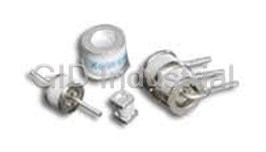
Gas Discharge Tubes 230VDC 10KADC 10AAC 1pF Solder Pad SMD
GTCN28-231M-R10
Part Number
GTCN28-231M-R10
Price
Request Quote
Manufacturer
LITTELFUSE, INC.
Lead Time
Request Quote
Category
Circuit Protection » Gas Discharge Tubes
Specifications
Manufacturer
Littelfuse, Inc.
Manufacturers Part #
GTCN28-231M-R10
Industry Aliases
GTCN28-231M-R10
Sub-Category
Gas Discharge Tubes
Packaging
Tray
Factory Pack Quantity
2000
Datasheet

Extracted Text
GAS DISCHARGE TUBES (GDTS) Littelfuse's GDTs (Gas Discharge Tubes) are placed in front of, and in parallel with, sensitive telecom equipment such as power lines, communication lines, signal lines and data transmission lines to help protect them from damage caused by transient surge voltages that may result from lightning strikes and equipment switching operations. These devices do not influence the signal in normal operation. However, in the event of an overvoltage surge, such as a lightning strike, the GDT switches to a low impedance state and diverts the energy away from the sensitive equipment. Our GDTs offer a high level of surge protection, a broad voltage range, low capacitance, and many form factors including new surface mount devices, which makes them suitable for applications such as Main Distribution Frame (MDF) modules, high data-rate telecom applications (e.g. ADSL, VDSL), and surge protection on power lines. Their low capacitance also results in less signal distortion. When used in a coordinated circuit protection solution with PolySwitch devices, they can help equipment manufacturers meet stringent safety regulatory standards. BENEFITS APPLICATIONS • Helps provide overvoltage fault protection against • Telecommunications damage caused by high energy surges - MDF modules, xDSL equipment, RF systems, antenna, base stations • Suitable for use in sensitive equipment due to impulse sparkover response • Industrial and Consumer Electronics - Power supplies, surge protectors, alarm systems, • Suitable for high-frequency applications irrigation systems • Highly reliable performance • New surface-mount devices for automated manufacturing FEATURES • RoHS compliant • Devices tested per ITU K.12 recommendations • Various lead configurations and surface-mount • Halogen free ≥ ≥ ≥ options (refers to: Br 900ppm, Cl 900ppm, Br+Cl 1500ppm) • Wide range of voltages (75V-4000V) • Optional fail-short mechanism • Wide range of form factors • Non radioactive materials (3mm, 5mm, 6mm, 7mm, 8mm diameter devices) • Devices certified to UL497B and UL1449 • Low capacitance and insertion loss • Crowbar device with low arc voltage • High accuracy spark-over voltages for high precision designs RoHS Compliant, ELV Compliant Specifications subject to change without notice. ©2016 Littelfuse, Inc. 73 Gas Discharge Tubes (GDTs) Figures G1-G2 — Typical Circuits for Gas Discharge Tubes Figure G1 Figure G2 TwTw o Electr o Electr ode Devices f ode Devices f or Ungr or Ungr ounded Cir ounded Cir cuits cuits Thr Thr ee Electr ee Electr ode Devices f ode Devices f or Gr or Gr ounded Cir ounded Cir cuits cuits PolyS PolyS witc witc h De h De vicevice PolyS PolyS witc witc h De h De vicevice (A) (A) (A’)(A’) (A) (A) (A’)(A’) Telecom Telecom Protected Protected Telecom Telecom Protected Protected GDT GDT GDT GDT Line Line Equipment Equipment Line Line Equipment Equipment (B) (B) Thyristor Thyristor (B’)(B’) (B) (B) Thyristors Thyristors (B’)(B’) PolyS PolyS witc witc h h Device Device Table G1 — Device Voltage Ratings, Surge Rating, Capacitance, Insulation Resistance and Agency Approval for Two-Electrode Gas Discharge Tubes DC Impulse Impulse Sparkover Sparkover Impulse Withstanding Insulation Voltage Voltage Discharge Current Voltage Capacitance Resistance UL Rating 8x20μs 8x20μs 10/700μs 10 Hits 300 Hits 10 Hits @ 100V/s (5 Hits Each (150 Hits Each (5 Times Each † Part Number ± 20% T olerance @ 1kV/μs Polarity) Polarity) Polarity) @1MHz @100V UL497B #E179610 DC 75* 600 90 600 GTCS23-XXXM-R01-2 1kA 100A 4kV <0.5pF 1,000 (MΩ) All Devices 140 600 150 600 200 700 230 700 ‡ GTCC23-XXXM-R01-2 300 900 1kA 100A 6kV <0.5pF 1,000 (MΩ) All Devices 350 1000 400 1000 * DCSO 60~105 † Devices <=150V measured @ 50V DC ‡ Effective output impedance: 40ohms AC Discharge DC DC Impulse Current Sparkover Impulse Holdover On-State Discharge Impulse (1s duration; Insulation Voltage Sparkover Voltage Voltage Voltage Current Life 10 hits) Capacitance Resistance UL Rating @ 100V/s Nominal ± 20% Per (@1A) 8x20μs 10x1000μs UL497B Part Number Tolerance @ 100V/μs @ 1kV/μs ITU K.12 (V) 10 Hits 300 Hits @ 50 Hz @ 1MHz @ 100V #E179610 DC 75 450 550 <52 20 GTCX25-XXXM-R02 2.5kA 100A 2.5Arms <1pF 10,000 (MΩ) All Devices 90 450 550 <52 20 140 500 600 <80 20 GTCX26-XXXM-R05 150 500 600 <80 20 5kA 100A 5Arms <1pF 10,000 (MΩ) All Devices 200 600 700 <135 20 230 600 700 <135 20 250 600 700 <135 20 GTCX28-XXXM-R05 5kA 100A 5Arms <1pF 10,000 (MΩ) All Devices 260 700 800 <135 20 300 800 900 <150 20 350 900 1000 <150 20 400 900 1000 <150 20 †† GTCX28-XXXM-R10 10kA 100A 10Arms <1pF 10,000 (MΩ) All Devices 420 900 1000 <150 20 470 1050 1150 <150 20 500 1100 1200 <150 20 550 1300 1400 <150 20 GTCX28-XXXM-R20** 20kA 100A 20Arms <1.5pF 10,000 (MΩ) All Devices 600 1300 1400 <150 20 ** GTCX28-XXXM-R20 parts only up to 350V †† <1.2pF for 75V and 90V devices. RoHS Compliant, ELV Compliant 74 Specifications subject to change without notice. ©2016 Littelfuse, Inc. Gas Discharge Tubes (GDTs) Table G2 — Device Voltage Ratings, Surge Rating, Capacitance, Insulation Resistance and Agency Approval for Two Electrode High-Voltage Gas Discharge Tubes DC Impulse Impulse Sparkover Sparkover AC Discharge Current, Discharge Current Voltage Voltage Impulse Life 50Hz 8/20μs Capacitance UL Rating @100V/s Multiple Hits ± 20% 10/1000μs (1s Duration: Single Hit, 10 Hits (5 Hits UL1449 Part Number Tolerance @ 100V/μs 100A 10 Hits) 9 Cycles Each Polarity) 1 Hit @ 1MHz #E332226 GTCA28-801M-R05 800 1400 300 times 5A N/A 5kA N/A <1pF 3 GTCA28-102M-R03 1000 1700 N/A 1A 5A 3kA 10kA <1pF 3 GTCA28-122M-R03 1200 1900 N/A 1A 5A 3kA 10kA <1pF 3 1500 GTCA28-152L-R03 2200 N/A 1A 5A 3kA 10kA <1pF 3 (± 15%) GTCA28-212M-R03 2100 2700 N/A 1A 5A 3kA 10kA <1pF 3 GTCA28-242M-R03 2400 3300 N/A 1A 5A 3kA 10kA <1pF 3 GTCA28-252M-R03 2500 3500 N/A 1A 5A 3kA 10kA <1pF 3 2700 † GTCA28-272L-R03 3700 300 Times N/A N/A 3kA 10kA <1pF 3 (± 15%)* GTCA28-302M-R03 3000 4000 N/A 1A 5A 3kA 10kA <1pF 3 3100 ‡ † GTCA28-312L-R03 3700 300 Times N/A N/A 3kA 10kA <1pF 3 (± 15%)* 3 GTCA28-362M-R03 3600 4600 N/A 1A 5A 3kA 10kA <1pF GTCA28-402M-R03 4000 5000 N/A 1A 5A 3kA 10kA <1pF 3 Table G3 — Device Voltage Ratings, Surge Rating, Capacitance, Insulation Resistance and Agency Approval for Three-Electrode Gas Discharge Tubes AC Discharge DC Impulse Current Sparkover Impulse DC Discharge Impulse (1s duration; Voltage Sparkover Voltage Holdover On-State Current Life 10 hits) Insulation (A-E) (B-E) (A-E) (B-E) Voltage Voltage (A+B-E) (A+B-E) (A+B-E) Capacitance Resistance UL Rating @ 100V/s Nominal ± 20% Per (@1A) 8x20μs 10x1000μs UL497B Part Number Tolerance @ 100V/μs @ 1kV/μs ITU K.12 (V) 10 Hits 300 Hits @ 50 Hz @ 1MHz @ 100V * #E179610 DC 75 450 550 <52 20 GTCX35-XXXM-R05 5kA 100A 5Arms <1pF 10,000 (MΩ) All Devices 90 450 550 <52 20 140 500 600 <80 20 GTCX36-XXXM-R05 150 500 600 <80 20 5kA 200A 5Arms <1pF 10,000 (MΩ) All Devices 200 600 700 <135 20 230 600 700 <135 20 250 600 700 <135 20 GTCX36-XXXM-R10 10kA 200A 10Arms <1pF 10,000 (MΩ) All Devices 260 700 800 <135 20 300 800 900 <150 20 350 900 1000 <150 20 400 900 1000 <150 20 GTCX37-XXXM-R10 420 900 1000 <150 20 10kA 200A 10Arms <1pF 10,000 (MΩ) All Devices 470 1050 1150 <150 20 500 1100 1200 <150 20 550 1300 1400 <150 20 GTCX38-XXXM-R10 10kA 200A 10Arms <1pF 10,000 (MΩ) All Devices 600 1300 1400 <150 20 * Insulation resistance measured at 50V for devices less than 150V. Insulation resistance measured at 250V for devices more than 500V. RoHS Compliant, ELV Compliant Specifications subject to change without notice. ©2016 Littelfuse, Inc. 75 Gas Discharge Tubes (GDTs) Figures G3-G11 — Dimensions for Gas Discharge Tubes Figure G3 — Two Electrode 3mm Product Dimensions Surface-mount Pad Layout - Surface-mount Devices (GTCS23-XXXM-R01) (GTCS23-XXXM-R01) X Y Z1 Z2 Nom Nom Nom Nom X mm 3.0 2.0 2.0 2.0 in* 0.118 0.079 0.079 0.079 1.01.0 1.01.0 Z1 Y Z2 * The dimensions in inches are rounded approximations. 4.5 ± 0.2 3.0 ± 0.2 4.5 ± 0.2 3.0 ± 0.2 Chip GDT Pad Layout - Chip GDT Devices (GTCC23-XXXM-R01) (GTCC23-XXXM-R01) X Y Z1 Z2 Nom Nom Nom Nom X mm 3.5 2.7 2.0 2.0 0.5 0.5 in* 0.138 0.106 0.079 0.079 0.5 0.5 3.2 ± 0.2 4.5 ± 0.3 Z1 Y Z2 3.2 ± 0.2 4.5 ± 0.3 * The dimensions in inches are rounded approximations. 60.0 ± 4.0 (2.364 ± 0.158) Figure G4 — Two Electrode 5mm Product Dimensions Axial Leads No Leads Surface-mount ø0.8 † 60.0 ± 4.0(0.032)REF 60.0 ± 4.0 (GTCA25-XXXM-R02) (GTCN25-XXXM-R02) (GTCS25-XXXM-R02) 0.5 (2.364 ± 0.158) (2.364 ± 0.158) (0.020)REF 60.0 ± 4.0 4.4 ± 0.2 5.0 ± 0.2 5.0 ± 0.2 5.0 ± 0.2 (0.173 ± 0.008) (2.364 ± 0.158) (0.197 ± 0.008) (0.197 ± 0.008) (0.197 ± 0.008) ø0.8 ø0.8 (0.032)REF (0.032)REF 0.5 0.5 ø0.8 (0.020)REF (0.020)REF 4.4 ± 0.2 (0.032)REF 5.0 ± 0.2 5.0 ± 0.2 5.0 ± 0.2 4.4 ± 0.2 5.0 ± 0.2 5.0 ± 0.2 5.0 ± 0.2 0.5 (0.173 ± 0.008) (0.197 ± 0.008) (0.197 ± 0.008) (0.173 ± 0.008) (0.197 ± 0.008) (0.197 ± 0.008) (0.197 ± 0.008) (0.197 ± 0.008) (0.020)REF 4.4 ± 0.2 5.0 ± 0.2 5.0 ± 0.2 5.0 ± 0.2 (0.173 ± 0.008) (0.197 ± 0.008) (0.197 ± 0.008) (0.197 ± 0.008) Pad Layout - Surface-mount Devices (GTCS25-XXXM-R02) Y X Y Z Nom Nom Nom X mm 6.0 3.9 1.3 in* 0.197 0.154 0.051 Z Y Y * The dimensions in inches are rounded approximations. Y † Parts with no leads are not solderable and are meant for insertion into magazine clips. X X X Z Z Z RoHS Compliant, ELV Compliant 76 Specifications subject to change without notice. ©2016 Littelfuse, Inc. ø3.0 ø3.0 5.0 ± 0.2 (0.197 ± 0.008) 5.00 ± 0.15 (0.197 ± 0.006) 5.0 ± 0.2 (0.197 ± 0.008) 2.7 ± 0.2 2.7 ± 0.2 5.00 ± 0.15 (0.197 ± 0.006) 5.0 ± 0.2 3.0 ± 0.2 3.0 ± 0.2 (0.197 ± 0.008) 5.00 ± 0.15 (0.197 ± 0.006) 5.00 ± 0.15 (0.197 ± 0.006) 5.0 ± 0.2 (0.197 ± 0.008) 5.00 ± 0.15 (0.197 ± 0.006) 5.00 ± 0.15 (0.197 ± 0.006) 5.00 ± 0.15 (0.197 ± 0.006) 5.00 ± 0.15 (0.197 ± 0.006) Gas Discharge Tubes (GDTs) 62.0 ± 2.0 (2.441 ± 0.079) (Cont’d) Figures G3-G11 — Dimensions for Gas Discharge Tubes Figure G5 — Two Electrode 6mm Product Dimensions ø0.8 (0.032)REF 0.6 Axial Leads No Leads Surface-mount 62.0 ± 2.0 62.0 ± 2.0 (0.024)REF † 6.2 ± 0.2 4.2 ± 0.2 4.2 ± 0.2 (GTCA26-XXXM-R05) (GTCN26-XXXM-R05) (GTCS26-XXXM-R05) 4.2 ± 0.2 (2.441 ± 0.079) (2.441 ± 0.079) (0.244 ± 0.008) (0.165 ± 0.008) (0.165 ± 0.008) (0.165 ± 0.008) 62.0 ± 2.0 (2.441 ± 0.079) ø0.8 ø0.8 (0.032)REF (0.032)REF 0.6 0.6 ø0.8 (0.024)REF (0.024)REF 6.2 ± 0.2 4.2 ± 0.2 4.2 ± 0.2 6.2 ± 0.2 4.2 ± 0.2 4.2 ± 0.2 4.2 ± 0.2 (0.032)REF 4.2 ± 0.2 (0.244 ± 0.008) (0.165 ± 0.008) (0.165 ± 0.008) (0.244 ± 0.008) (0.165 ± 0.008) (0.165 ± 0.008) (0.165 ± 0.008) 0.6 (0.165 ± 0.008) (0.024)REF 6.2 ± 0.2 4.2 ± 0.2 4.2 ± 0.2 4.2 ± 0.2 (0.244 ± 0.008) (0.165 ± 0.008) (0.165 ± 0.008) (0.165 ± 0.008) Pad Layout - Surface-mount Devices (GTCS26-XXXM-R05) Y X Y Z Nom Nom Nom X mm 7.0 3.7 1.3 in* 0.276 0.146 0.051 62.0 ± 4.0 (2.441 ± 0.157) Z * The dimensions in inches are rounded approximations. Y Y † Parts with no leads are not solderable and are meant for insertion into magazine clips. Y X X ø0.8 Figure G6 — Two Electrode 8mm Product Dimensions (0.032)REF 0.5 0.5 Axial Leads No Leads Surface-mount X (0.02)REF (0.02)REF 62.0 ± 4.0 8.2 ± 0.2 6.0 ± 0.2 6.0 ± 0.2 62.0 ± 4.0 6.0 ± 0.2 † Z (GTCA28-XXXM-R05, R10 & R20) (GTCN28-XXXM-R05, R10 & R20) (GTCS28-XXXM-R05, R10 & R20) Z (0.323 ± 0.008) (0.236 ± 0.008) (2.441 ± 0.157) (0.236 ± 0.008) (2.441 ± 0.157) (0.236 ± 0.008) 62.0 ± 4.0 (2.441 ± 0.157) Z ø0.8 ø0.8 (0.032)REF (0.032)REF 0.5 ø0.8 0.5 0.5 0.5 (0.02)REF (0.032)REF (0.02)REF (0.02)REF (0.02)REF 8.2 ± 0.2 6.0 ± 0.2 8.2 ± 0.2 6.0 ± 0.2 6.0 ± 0.2 6.0 ± 0.2 6.0 ± 0.2 6.0 ± 0.2 0.5 0.5 (0.323 ± 0.008) (0.236 ± 0.008) (0.236 ± 0.008) (0.323 ± 0.008) (0.236 ± 0.008) (0.236 ± 0.008) (0.236 ± 0.008) (0.236 ± 0.008) (0.02)REF (0.02)REF 8.2 ± 0.2 6.0 ± 0.2 6.0 ± 0.2 6.0 ± 0.2 (0.323 ± 0.008) (0.236 ± 0.008) (0.236 ± 0.008) (0.236 ± 0.008) Pad Layout - Surface-mount Devices (GTCS28-XXXM-R05, R10 & R20) Y X Y Z Nom Nom Nom X mm 9.0 5.6 1.2 in* 0.354 0.22 0.047 Z * The dimensions in inches are rounded approximations. † Parts with no leads are not solderable and are meant for insertion into magazine clips. Y Y Y Figure G7 — Two Electrode 8mm High Voltage Product Dimensions X X X Axial Leads (GTCA28-XXXM-R0X) Z Z ø0.8 Z 6 ± 0.2 62 ± 4 RoHS Compliant, ELV Compliant Specifications subject to change without notice. ©2016 Littelfuse, Inc. 77 ø6.0 ± 0.2 ø8.0 ± 0.2 (0.236 ± 0.008) (0.315 ± 0.008) 6.2 ± 0.2 8.2 ± 0.2 (0.244 ± 0.008) (0.323 ± 0.008) ø6.0 ± 0.2 ø8.0 ± 0.2 (0.236 ± 0.008) (0.315 ± 0.008) ø8.0 ± 0.2 ø6.0 ± 0.2 (0.315 ± 0.008) (0.236 ± 0.008) 8.2 ± 0.2 6.2 ± 0.2 (0.323 ± 0.008) (0.244 ± 0.008) ø8.0 ± 0.2 ø6.0 ± 0.2 (0.315 ± 0.008) (0.236 ± 0.008) ø8.0 ± 0.2 (0.315 ± 0.008) ø6.0 ± 0.2 ø8 ± 0.2 (0.236 ± 0.008) 8.2 ± 0.2 6.2 ± 0.2 (0.323 ± 0.008) (0.244 ± 0.008) ø8.0 ± 0.2 ø6.0 ± 0.2 (0.315 ± 0.008) (0.236 ± 0.008) ø8.0 ± 0.2 ø6.0 ± 0.2 (0.315 ± 0.008) (0.236 ± 0.008) ø8.0 ± 0.2 ø6.0 ± 0.2 (0.315 ± 0.008) (0.236 ± 0.008) 8.2 ± 0.2 6.2 ± 0.2 (0.323 ± 0.008) (0.244 ± 0.008) ø8.0 ± 0.2 (0.315 ± 0.008) ø6.0 ± 0.2 (0.236 ± 0.008) ø8.0 ± 0.2 (0.315 ± 0.008) ø8.0 ± 0.2 ø6.0 ± 0.2 ø6.0 ± 0.2 (0.315 ± 0.008) (0.236 ± 0.008) (0.236 ± 0.008) ø8.0 ± 0.2 (0.315 ± 0.008) ø6.0 ± 0.2 (0.236 ± 0.008) +0.0 11.4 –2.0 +0.000 +0.0 0.449 ( ) 11.4 –0.079 –2.0 8.3 ± 0.3 +0.000 0.449 ( ) –0.079 (0.327 ± 0.012) 8.3 ± 0.3 7.6 ± 0.2 7.6 ± 0.2 (0.327 ± 0.012) (0.299 ± 0.008) (0.299 ± 0.008) ø5.0 ± 0.2 ø5.0 ± 0.2 ø5.0 ± 0.2 MAX 5.9 (0.197 ± 0.008) (0.197 ± 0.008) (0.197 ± 0.008) (0.232) 13.0 ± 0.5 12.0 ± 0.5 7.6 ± 0.2 (0.512 ± 0.020) (0.473 ± 0.020) (0.299 ± 0.008) 4.5 4.5 (0.177) REF (0.177) REF ø0.8 ø0.8 3.8 ± 0.3 (0.032) 3.8 ± 0.3 (0.032) (0.151 ± 0.012) (0.151 ± 0.012) 8.3 ± 0.3 7.6 ± 0.2 1.6 (0.327 ± 0.012) (0.063)REF (0.299 ± 0.008) ø5.0 ± 0.2 MAX 5.9 Gas Discharge Tubes (GDTs) ø5.0 ± 0.2 ø5.0 ± 0.2 (0.197 ± 0.008) (0.232) (0.197 ± 0.008) (0.197 ± 0.008) 0.4 0.4 1.6 (0.016) REF (0.016) REF 3X 30.0 ± 2.0 (0.063)REF ø5.0 ± 0.2 ø5.0 ± 0.2 (1.182 ± 0.079) 7.6 ± 0.2 (0.197 ± 0.008) (0.197 ± 0.008) ø0.8 7.6 ± 0.2 (0.299 ± 0.008) (0.032) (Cont’d) Figures G3-G11 — Dimensions for Gas Discharge Tubes (0.299 ± 0.008) Figure G8 — Three Electrode 5mm Product Dimensions Axial Leaded Axial Leaded with-FT No Leads +0.0 11.4 –2.0 +0.0 † (GTCA35-XXXM-R05) (GTCA35-XXXM-R05-FT) (GTCN35-XXXM-R05) 11.4 +0.0–2.0 00 +0.0 +0.0 (0.449 ) +0.0 –0.079 11.4 +0.000 –2.0 11.4 +0.0 11.4 –2.0 –2.0 0.449 ( ) 11.4 +0.0 –0.079 –2.0 Y1 Y2 8.3 ± 0.3 +0.000 11.4 +0.000 –2.0 +0.000 +0.0 (0.449 ) +0.0 –0.079 (0.449 ) 8.3 ± 0.3 +0.000 (0.449 ) –0.079 (0.327 ± 0.012) 11.4 –0.079 11.4 –2.0 0.449 8.3 ± 0.3 +0.000 –2.0 ( ) +0.0 –0.079 (0.327 ± 0.012) 0.449 ( ) 11.4 7.6 ± 0.2 7.6 ± 0.2 –0.079 8.3 ± 0.3 +0.000 (0.327 ± 0.0 8.3 ± 0.3 12) 8.3 ± 0.3 –2.0 +0.000 0.449 0.449 ( ) ø5.0 ± 0.2 ( ) (0.299 ± 0.0 7.6 ± 0.2 08) –0.079 (0.299 ± 0.0 7.6 ± 0.2 08) –0.079 (0.327 ± 0.012) (0.327 ± 0.012) 8.3 ± 0.3 (0.327 ± 0.0 +0.0 12)00 8.3 ± 0.3 0.449 8.3 ± 0.3 (0.197 ± 0.008) ( ) (0.299 ± 0.008) (0.299 ± 0.008) –0.079 (0.327 ± 0.012) 7.6 ± 0.2 7.6 ± 0.2 7.6 ± 0.2 7.6 ± 0.2 X (0.327 ± 0.012) 8.3 ± 0.3 (0.327 ± 0.012) (0.299 ± 0.008) (0.299 ± 0.008) (0.299 ± 0.008) (0.299 ± 0.008) 7.6 ± 0.2 7.6 ± 0.2 (0.327 ± 0.012) MAX 5.9 ø5.0 ± 0.2 ø5.0 ± 0.2 ø5.0 ± 0.2 (0.299 ± 0.008) (0.299 ± 0.008) ø5.0 ± 0.2 ø5.0 ± 0.2 ø5.0 ± 0.2 (0.232) MAX 5.9 (0.197 ± 0.008) (0.197 ± 0.008) (0.197 ± 0.008) (0.197 ± 0.008) (0.197 ± 0.008) (0.197 ± 0.008) (0.232) 7.6 ± 0.2 MAX 5.9 MAX 5.9 ø5.0 ± 0.2 ø5.0 ± 0.2 ø5.0 ± 0.2 ø5.0 ± 0.2 ø5.0 ± 0.2 ø5.0 ± 0.2 (0.299 ± 0.008) (0.232) (0.232) (0.197 ± 0.008) (0.197 ± 0.008) (0.197 ± 0.008) ø5.0 ± 0.2 (0.197 ± 0.0 ø5.0 ± 0. 08)2 ø5.0 ± 0.2 (0.197 ± 0.008) MAX 5.9 (0.197 ± 0.008) Z1 Z2 (0.197 ± 0.008) (0.197 ± 0.008) (0.197 ± 0.008) (0.232) 13.0 ± 0.5 12.0 ± 0.5 7.6 ± 0.2 (0.512 ± 0.020) 13.0 ± 0.5 (0.473 ± 0.020) 12.0 ± 0.5 7.6 ± 0.2 (0.299 ± 0.008) (0.512 ± 0.020) (0.473 ± 0.020) 13.0 ± 0.5 12.0 ± 0.5 13.0 ± 0.5 12.0 ± 0.5 4.5 4.5 (0.299 ± 0.008) 7.6 ± 0.2 7.6 ± 0.2 (0.512 ± 0.020) (0.473 ± 0.020) 4.5 4.5 (0.512 ± 0.020) (0.473 ± 0.020) (0.177) REF (0.177) REF 13.0 ± 0.5 12.0 ± 0.5 Dimensions in these drawings (0.299 ± 0.008) 7.6 ± 0.2 (0.299 ± 0.008) (0.177) REF (0.177) REF (0.512 ± 0.020) (0.473 ± 0.020) 4.5 4.5 4.5 4.5 (0.299 ± 0.008) are in millimeters (inches) (0.177) REF (0.177) REF 4.5 (0.177) REF 4.5 (0.177) REF ø0.8 ø0.8 3.8 ± 0.3 ø0.8 3.8 ± 0.3 ø0.8 (0.177) REF (0.177) REF (0.032) (0.032) (0.151 ± 0.0 3.8 ± 0.3 12) (0.032) (0.151 ± 0.0 3.8 ± 0.3 12) (0.032) ø0.8 ø0.8 ø0.8 ø0.8 (0.151 ± 0.012) (0.151 ± 0.012) 3.8 ± 0.3 (0.032) 3.8 ± 0.3 (0.032) ø0.8 3.8 ± 0.3 (0.032) ø0.8 3.8 ± 0.3 (0.032) (0.151 ± 0.012) (0.151 ± 0.012) 3.8 ± 0.3 (0.032) (0.151 ± 0.0 3.8 ± 0.3 12) (0.032) (0.151 ± 0.012) (0.151 ± 0.012) (0.151 ± 0.012) +0.0 11.4 –2.0 No Leads with-FT Surface-mount T Leaded +0.000 +0.0 0.449 8.3 ± 0.3 ( ) 11.4 † –0.079 –2.0 (GTCN35-XXXM-R05-FT) (GTCS35-XXXM-R05) (GTCT35-XXXM-R05) 7.6 ± 0.2 8.3 ± 0.3 1.6 (0.327 ± 0.012) 8.3 ± 0.3 +0.000 (0.299 ± 0.0 7.6 ± 0.2 08) (0.063)REF 1.6 (0.327 ± 0.012) 0.449 ( ) –0.079 8.3 ± 0.3 8.3 ± 0.3 (0.327 ± 0.012) (0.063)REF (0.299 ± 0.008) 7.6 ± 0.2 8.3 ± 0.3 7.6 ± 0.2 1.6 1.6 (0.327 ± 0.012) 8.3 ± 0.3 (0.327 ± 0.012) 7.6 ± 0.2 7.6 ± 0.2 (0.299 ± 0.008) (0.327 ± 0.012) (0.063)REF (0.299 ± 0.008) (0.063)REF 7.6 ± 0.2 1.6 (0.327 ± 0.012) MAX 5.9 (0.299 ± 0.008) ø5.0 ± 0.2 (0.299 ± 0.008) ø5.0 ± 0.2 ø5.0 ± 0.2 (0.063)REF (0.299 ± 0.008) ø5.0 ± 0.2 (0.232) MAX 5.9 (0.197 ± 0.008) (0.197 ± 0.0 ø5.0 ± 0. 08) 2 (0.197 ± 0.0 ø5.0 ± 0. 08) 2 (0.197 ± 0.008) (0.232) MAX 5.9 (0.197 ± 0.008) (0.197 ± 0.008) MAX 5.9 ø5.0 ± 0.2 ø5.0 ± 0.2 ø5.0 ± 0.2 ø5.0 ± 0.2 ø5.0 ± 0.2 ø5.0 ± 0.2 ø5.0 ± 0.2 ø5.0 ± 0.2 ø5.0 ± 0.2 MAX 5.9 (0.232) (0.232) (0.197 ± 0.008) ø5.0 ± 0.2 (0.197 ± 0.008) MAX 5.9 0.4 (0.197 ± 0.008) 0.4 (0.197 ± 0.008) (0.197 ± 0.008) (0.197 ± 0.008) ø5.0 ± 0.2 ø5.0 ± 0.2 (0.197 ± 0.008) (0.197 ± 0.008) (0.197 ± 0.008) (0.232) 1.6 0.4 (0.197 ± 0.008) 0.4 (0.232) (0.016) REF (0.016) REF (0.197 ± 0.008) (0.197 ± 0.008) 3X 30.0 ± 2.0 (0.063)REF 1.6 ø5.0 ± 0.2 ø5.0 ± 0.2 (0.016) REF (0.016) REF 3X 30.0 ± 2.0 0.4 (0.063)REF 0.4 7.6 ± 0.2 0.4 0.4 (1.182 ± 0.079) ø5.0 ± 0.2 ø5.0 ± 0.2 (0.197 ± 0.008) (0.197 ± 0.008) ø0.8 1.6 1.6 (1.182 ± 0.079) (0.016) REF 7.6 ± 0.2 (0.016) REF (0.299 ± 0.0 7.6 ± 0.2 08) 0.4 (0.016) REF 0.4 (0.016) REF (0.197 ± 0.008) (0.197 ± 0.008) 3X 30.0 ± 2.0 ø0.8 (0.063)REF 3X 30.0 ± 2.0 (0.063)REF (0.032) ø5.0 ± 0.2 ø5.0 ± 0.2 1.6 ø5.0 ± 0.2 ø5.0 ± 0.2 13.0 ± 0.5 12.0 ± 0.5 (0.299 ± 0.0 7.6 ± 0.2 08) (0.299 ± 0.008) (0.016) REF (0.016) REF 7.6 ± 0.2 (1.182 ± 0.079) (0.032) 7.6 ± 0.2 3X 30.0 ± 2.0 (0.063)REF (1.182 ± 0.079) 7.6 ± 0.2 (0.197 ± 0.008) (0.197 ± 0.008) ø5.0 ± 0.2 (0.197 ± 0.008) ø5.0 ± 0.2 (0.197 ± 0.008) (0.512 ± 0.020) (0.473 ± 0.020) ø0.8 (0.299 ± 0.008) ø0.8 7.6 ± 0.2 (0.299 ± 0.008) 7.6 ± 0.2 (0.299 ± 0.008) (1.182 ± 0.079) 7.6 ± 0.2 (0.299 ± 0.008) (0.197 ± 0.008) (0.197 ± 0.008) (0.032) ø0.8 (0.032) 4.5 4.5 (0.299 ± 0.008) (0.299 ± 0.008) 7.6 ± 0.2 (0.299 ± 0.008) (0.032) (0.177) REF (0.177) REF (0.299 ± 0.008) ø0.8 ø0.8 3.8 ± 0.3 (0.032) 3.8 ± 0.3 (0.032) (0.151 ± 0.012) (0.151 ± 0.012) Pad Layout - Surface-mount Devices (GTCS35-XXXM-R05) Y1 Y2 Y1 Y2 X Y1 Y2 Z1 Z2 Y1 Y2 Y1 Y2 ø5.0 ± 0.2 Nom Nom Nom Nom Nom Y1 Y2 (0.197 ± 0.0 ø5.0 ± 0. 08) 2 8.3 ± 0.3 X 7.6 ± 0.2 (0.197 ± 0.008) 1.6 mm 6.0 3.6 3.6 2.5 1.3 (0.327 ± 0.012) ø5.0 ± 0.2 ø5.0 ± 0.2 X (0.063)REF (0.299 ± 0.008) (0.197 ± 0.008) ø5.0 ± 0.2 (0.197 ± 0.008) in* 0.236 0.142 0.142 0.098 0.051 X X (0.197 ± 0.008) X 7.6 ± 0.2 ø5.0 ± 0.2 MAX 5.9 7.6 ± 0.2 ø5.0 ± 0.2 ø5.0 ± 0.2 (0.299 ± 0.008) (0.197 ± 0.008) (0.232) Z1 Z2 (0.299 ± 0.008) (0.197 ± 0.008) (0.197 ± 0.008) 7.6 ± 0.2 7.6 ± 0.2 Z1 Z2 (0.299 ± 0.008) 7.6 ± 0.2 (0.299 ± 0.008) 0.4 Z1 Z2 0.4 Z1 Z2 (0.299 ± 0.008) 1.6 (0.016) REF (0.016) REF Z1 Z2 * The dimensions in inches are rounded approximations. 3X 30.0 ± 2.0 (0.063)REF ø5.0 ± 0.2 ø5.0 ± 0.2 † Parts with no leads are not solderable and are meant for insertion into magazine clips. (1.182 ± 0.079) 7.6 ± 0.2 (0.197 ± 0.008) (0.197 ± 0.008) ø0.8 7.6 ± 0.2 (0.299 ± 0.008) (0.032) (0.299 ± 0.008) Y1 Y2 ø5.0 ± 0.2 (0.197 ± 0.008) X 7.6 ± 0.2 (0.299 ± 0.008) Z1 Z2 RoHS Compliant, ELV Compliant 78 Specifications subject to change without notice. ©2016 Littelfuse, Inc. 9.2 ± 0.2 (0.362 ± 0.008) 8.2 ± 0.3 8.0 ± 0.2 8.2 ± 0.3 (0.323 ± 0.012) (0.315 ± 0.008) ø6.0 ± 0.2 (0.323 ± 0.012) ø6.0 ± 0.2 (0.236 ± 0.008) (0.236 ± 0.008) ø6.0 ± 0.2 MAX 7.0 (0.236 ± 0.008) (0.276) Gas Discharge Tubes (GDTs) 13.0 ± 0.5 12.3 ± 0.5 (0.512 ± 0.020) (0.485 ± 0.020) 8.0 ± 0.2 (0.315 ± 0.008) 8.0 ± 0.5 ø0.8 ø0.8 ø0.8 (0.315 ± 0.020) (0.032) REF (0.032) REF (0.032) REF (Cont’d) Figures G3-G11 — Dimensions for Gas Discharge Tubes 4.7 ± 0.5 4.7 ± 0.5 (0.185 ± 0.020) (0.185 ± 0.020) 3.8 ± 0.3 (0.150 ± 0.012) Figure G9 — Three Electrode 6mm Product Dimensions Axial Leaded Axial Leaded with-FT No Leads 9.2 ± 0.2 † (GTCA36-XXXM-R05 and R10) (GTCA36-XXXM-R05 and R10-FT) 9.2 ± 0.2 (GTCN36-XXXM-R05 and R10) 9.2 ± 0.2 (0.362 ± 0.008) 9.2 ± 0.2 9.2 ± 0.2 (0.362 ± 0.0 8.2 ± 0.3 08) (0.362 ± 0.008) 8.0 ± 0.2 8.2 ± 0.3 (0.362 ± 0.008) 8.2 ± 0.3 (0.362 ± 0.008) 8.2 ± 0.3 (0.323 ± 0.012) 8.0 ± 0.2 9.2 ± 0.2 8.0 ± 0.2 8.2 ± 0.3 (0.315 ± 0.008) 8.2 ± 0.3 8.2 ± 0.3 ø6.0 ± 0.2 (0.323 ± 0.012) ø6.0 ± 0.2 8.2 ± 0.3 (0.323 ± 0.012) 8.0 ± 0.2 (0.323 ± 0.012) 8.0 ± 0.2 8.2 ± 0.3 (0.315 ± 0.008) 8.2 ± 0.3 8.2 ± 0.3 (0.362 ± 0.008) ø6.0 ± 0.2 (0.315 ± 0.008) (0.323 ± 0.012) ø6.0 ± 0.2 ø6.0 ± 0.2 (0.323 ± 0.0 (0.323 ± 0.0 12)12) ø6.0 ± 0.2 (0.236 ± 0.008) 0.75 (0.236 ± 0.008) (0.323 ± 0.012) 9.2 ± 0.2 (0.315 ± 0.008) 8.2 ± 0.3(0.315 ± 0.008) ø6.0 ± 0.2 (0.323 ± 0.012) ø6.0 ± 0.2 ø6.0 ± 0.2 (0.323 ± 0.0 (0.323 ± 0.0 1212 ) ) ø6.0 ± 0.2 (0.236 ± 0.008) 8.0 ± 0.2 (0.236 ± 0.008) (0.236 ± 0.008) (0.236 ± 0.008) 8.2 ± 0.3 (0.030) REF (0.362 ± 0.008) ø6.0 ± 0.2 (0.323 ± 0.012) (0.236 ± 0.008) (0.236 ± 0.008) (0.236 ± 0.008) (0.236 ± 0.008) (0.315 ± 0.008) ø6.0 ± 0.2 (0.323 ± 0.012) ø6.0 ± 0.2 (0.236 ± 0.008) ø6.0 ± 0.2 MAX 7.0 ø6.0 ± 0.2 (0.236 ± 0.008) MAX 7.0 (0.236 ± 0.008) ø6.0 ± 0.2 MAX 7.0 (0.236 ± 0.008) (0.276) ø6.0 ± 0.2 MAX 7.0 ø6.0 ± 0.2 MAX 7.0 (0.236 ± 0.008) (0.276) (0.236 ± 0.008) (0.276) ø6.0 ± 0.2 ø6.0 ± 0.2 13.0 ± 0.5 MAX 7.0 (0.236 ± 0.008) 12.3 ± 0.5 (0.276) (0.236 ± 0.008) (0.276) ø6.0 ± 0.2 MAX 7.0 13.0 ± 0.5 (0.236 ± 0.008) 12.3 ± 0.5 (0.236 ± 0.008) 13.0 ± 0.5 12.3 ± 0.5 (0.512 ± 0.020) (0.276) (0.485 ± 0.020) 13.0 ± 0.5 (0.236 ± 0.008) (0.276) 12.3 ± 0.5 13.0 ± 0.5 12.3 ± 0.5 (0.512 ± 0.020) (0.485 ± 0.020) (0.512 ± 0.020) (0.485 ± 0.020) 8.0 ± 0.2 14.0 ± 0.5 (0.512 ± 0.020) (0.485 ± 0.020) (0.512 ± 0.020) (0.485 ± 0.020) 8.0 ± 0.2 8.0 ± 0.2 13.0 ± 0.5 (0.315 ± 0.008) 12.3 ± 0.5 8.0 ± 0.5 ø0.8 ø0.8 ø0.8 (0.552 ± 0.020) 8.0 ± 0.2 8.0 ± 0.2 (0.315 ± 0.008) 8.0 ± 0.5 (0.315 ± 0.008) ø0.8 (0.512 ± 0.020)ø0.8 8.0 ± 0.5 (0.485 ± 0.020) ø0.8 (0.315 ± 0.020) ø0.8 ø0.8 ø0.8 (0.032) REF (0.032) REF (0.032) REF 8.0 ± 0.2 (0.315 ± 0.008) 8.0 ± 0.2 8.0 ± 0.5 (0.315 ± 0.008) 8.0 ± 0.5 ø0.8 ø0.8 ø0.8 ø0.8 ø0.8 (0.315 ± 0.020) ø0.8 (0.032) REF (0.032) REF 8.0 ± 0.2 (0.315 ± 0.020) (0.032) REF (0.032) REF (0.032) REF (0.032) REF (0.315 ± 0.008) (0.315 ± 0.008) (0.315 ± 0.020) (0.315 ± 0.020) (0.032) REF (0.032) REF (0.032) REF (0.032) REF (0.032) REF (0.032) REF ø0.8 (0.315 ± 0.008) 8.0 ± 0.5 ø0.8 ø0.8 ø0.8 (0.032) REF (0.315 ± 0.020) (0.032) REF (0.032) REF 4.7 ± 0.5 4.7 ± 0.5 (0.032) REF 4.7 ± 0.5 4.7 ± 0.5 4.7 ± 0.5 4.7 ± 0.5 (0.185 ± 0.020) (0.185 ± 0.020) 3.8 ± 0.3 4.7 ± 0.5 4.7 ± 0.5 4.7 ± 0.5 4.7 ± 0.5 (0.185 ± 0.020) (0.185 ± 0.020) Dimensions in these drawings (0.185 ± 0.020) (0.185 ± 0.020) 3.8 ± 0.3 3.8 ± 0.3 (0.150 ± 0.012) (0.185 ± 0.020) (0.185 ± 0.020) (0.185 ± 0.020) (0.185 ± 0.020) 3.8 ± 0.3 4.7 ± 0.5 4.7 ± 0.5 3.8 ± 0.3 (0.150 ± 0.012) (0.150 ± 0.012) are in millimeters (inches) 3.8 ± 0.3 (0.150 ± 0.012) (0.185 ± 0.020) (0.1 (0.1 85 ± 0.020) 50 ± 0.012) 3.8 ± 0.3 (0.150 ± 0.012) (0.150 ± 0.012) No Leads with-FT Radial Leaded Radial Leaded with-FT † (GTCN36-XXXM-R05 and R10-FT) (GTCR36-XXXM-R05 and R10) (GTCR36-XXXM-R05 and R10-FT) 8.3 ± 0.3 1.2 9.2 ± 0.2 8.2 ± 0.3 ø6.0 ± 0.2 (0.327 ± 0.012) ø6.0 ± 0.2 0.75 (0.047) REF 9.2 ± 0.2 (0.362 ± 0.008) Y1 Y2 8.2 ± 0.3 8.2 ± 0.3 0.75 (0.323 ± 0.012) (0.236 ± 0.008) 0.75 (0.236 ± 0.008) (0.030) REF 9.2 ± 0.2 9.2 ± 0.2 8.2 ± 0.3 ø6.0 ± 0.2 (0.362 ± 0.008) 8.2 ± 0.3 8.2 ± 0.3 8.0 ± 0.2 0.75 (0.323 ± 0.012) 0.75 8.2 ± 0.3 (0.323 ± 0.012) 9.2 ± 0.2(0.030) REF 9.2 ± 0.2 ø6.0 ± 0.2 (0.030) REF (0.362 ± 0.0 (0.362 ± 0.0 08) 08) (0.323 ± 0.012) ø6.0 ± 0.2 (0.236 ± 0.008) (0.323 ± 0.012) (0.323 ± 0.012) (0.315 ± 0.008) (0.030) REF ø6.0 ± 0.2 (0.030) REF (0.323 ± 0.012) ø6.0 ± 0.2 ø6.0 ± 0.2 ø6.0 ± 0.2 (0.362 ± 0.0 8.2 ± 0.3 08) (0.362 ± 0.008) (0.236 ± 0.008) 0.75 9.2 ± 0.2 (0.236 ± 0.008) (0.236 ± 0.008) (0.236 ± 0.0 (0.236 ± 0.0 08) 08) (0.236 ± 0.0 6.0 ± 0.2 08) (0.323 ± 0.012) 6.0 ± 0.2 MAX 7.0 (0.030) REF (0.362 ± 0.008) ø6.0 ± 0.2 ø6.0 ± 0.2 ø6.0 ± 0.2 MAX 7.0 (0.236 ± 0.008) (0.236 ± 0.008) (0.276) (0.236 ± 0.008) ø6.0 ± 0.2 ø6.0 ± 0.2 X ø6.0 ± 0.2 MAX 7.0 ø6.0 ± 0.2 (0.236 ± 0.008) (0.236 ± 0.008) MAX 7.0 (0.276) ø6.0 ± 0.2 MAX 7.0 ø6.0 ± 0.2 ø6.0 ± 0.2 ø6.0 ± 0.2 ø6.0 ± 0.2 (0.236 ± 0.008) MAX 7.0 (0.236 ± 0.008) MAX 7.0 (0.236 ± 0.008) (0.276) (0.236 ± 0.008) (0.276) (0.236 ± 0.008) (0.276) (0.236 ± 0.008) 14.0 ± 0.5 (0.236 ± 0.008) (0.236 ± 0.008) 1.0 (0.236 ± 0.0 1.0 08) (0.276) (0.276) ø6.0 ± 0.2 ø6.0 ± 0.2 MAX 7.0 14.0 ± 0.5 14.0 ± 0.5 (0.552 ± 0.020) (0.039) REF (0.039) REF 13.0 ± 0.5 1.2 12.3 ± 0.5 (0.236 ± 0.008) 14.0 ± 0.5 (0.236 ± 0.008) 14.0 ± 0.5 6.0 ± 0.2 (0.276) 6.0 ± 0.2 (0.552 ± 0.020) (0.552 ± 0.020) 8.0 ± 0.2 (0.047) REF 8.0 ± 0.2 (0.512 ± 0.020) (0.485 ± 0.020) (0.552 ± 0.020) (0.552 ± 0.020) 8.2 ± 0.2 (0.236 ± 0.008) (0.236 ± 0.008) 8.0 ± 0.2 8.0 ± 0.2 14.0 ± 0.5 8.0 ± 0.2 (0.315 ± 0.008) 8.0 ± 0.2 (0.315 ± 0.008) 8.0 ± 0.2 8.2 ± 0.2 8.0 ± 0.2 (0.323 ± 0.0 8.0 ± 0. 08) 2 Z1 Z2 (0.315 ± 0.008) ø0.8 8.0 ± 0.2 8.0 ± 0.2 (0.315 ± 0.008) (0.552 ± 0.020) (0.315 ± 0.008) (0.315 ± 0.008) (0.315 ± 0.008) 8.0 ± 0.5 ø0.8 ø0.8 (0.323 ± 0.008) (0.315 ± 0.008) ø0.8 ø0.8 (0.315 ± 0.008) ø0.8 (0.032) REF (0.315 ± 0.008) (0.315 ± 0.008) 8.0 ± 0.2 8.0 ± 0.2 ø0.8 (0.315 ± 0.020) ø0.8 (0.032) REF (0.032) REF (0.032) REF (0.032) REF (0.032) REF (0.315 ± 0.008) (0.315 ± 0.008) (0.032) REF (0.032) REF ø0.8 (0.032) REF 4.7 ± 0.5 4.7 ± 0.5 3.8 ± 0.3 3.8 ± 0.3 3.8 ± 0.3 (0.185 ± 0.020) (0.185 ± 0.020) (0.150 ± 0.012) 3.8 ± 0.3 3.8 ± 0.3 3.8 ± 0.3 (0.150 ± 0.012) (0.150 ± 0.012) (0.150 ± 0.012) (0.150 ± 0.012) (0.150 ± 0.012) 3.8 ± 0.3 (0.150 ± 0.012) Surface-mount Pad Layout - Surface-mount Devices 1.2 8.3 ± 0.3 (GTCS36-XXXM-R05 and R10) (GTCS36-XXXM-R05 and R10) 1.2 8.3 ± 0.3 1.2 8.3 ± 0.3 (0.047) REF ø6.0 ± 0.2 (0.327 ± 0.012) ø6.0 ± 0.2 Y1 Y2 1.2 8.3 ± 0.3 1.2 8.3 ± 0.3 (0.047) REF ø6.0 ± 0.2 (0.327 ± 0.012) ø6.0 ± 0.2 (0.047) REF ø6.0 ± 0.2 (0.327 ± 0.012) ø6.0 ± 0.2 (0.236 ± 0.008) (0.236 ± 0.008) Y1 Y2 Y1 Y2 (0.047) REF ø6.0 ± 0.2 (0.327 ± 0.012) ø6.0 ± 0.2 (0.047) REF ø6.0 ± 0.2 (0.327 ± 0.012) ø6.0 ± 0.2 (0.236 ± 0.008) (0.236 ± 0.008) Y1 Y2 (0.236 ± 0.008) 1.2 (0.236 ± 0.008) 8.3 ± 0.3 Y1 Y2 (0.236 ± 0.008) (0.236 ± 0.008) (0.236 ± 0.008) (0.236 ± 0.008) (0.047) REF ø6.0 ± 0.2 (0.327 ± 0.012) ø6.0 ± 0.2 8.2 ± 0.3 Y1 Y2 0.75 6.0 ± 0.2 6.0 ± 0.2 9.2 ± 0.2 (0.236 ± 0.008) (0.236 ± 0.008) MAX 7.0 (0.323 ± 0.012) 6.0 ± 0.2 6.0 ± 0.2 X Y1 (0.030) REF Y2 Z1 Z2 6.0 ± 0.2 6.0 ± 0.2 ø6.0 ± 0.2 (0.236 ± 0.008) (0.236 ± 0.008) (0.362 ± 0.008) MAX 7.0 MAX 7.0 (0.276) 6.0 ± 0.2 6.0 ± 0.2 6.0 ± 0.2 6.0 ± 0.2 X (0.236 ± 0.008) (0.236 ± 0.008) MAX 7.0 (0.236 ± 0.008) MAX 7.0 (0.236 ± 0.008) (0.236 ± 0.008) (0.276) (0.276) Nom Nom Nom Nom Nom X (0.236 ± 0.008) (0.236 ± 0.008) (0.236 ± 0.008) (0.236 ± 0.008) X (0.276) (0.276) 6.0 ± 0.2 6.0 ± 0.2 X 1.0X MAX 7.0 1.0 (0.236 ± 0.008) (0.236 ± 0.008) 1.0 1.0 1.0 ø6.0 ± 0.2 1.0 (0.039) REF (0.276) mm 7.0 ø6.0 ± 0.2 (0.039) REF 3.6 3.6 2.5 2.0 MAX 7.0 1.2 X 1.0 6.0 ± 0.2 1.0 6.0 ± 0.2 1.0 1.0 (0.039) REF (0.039) REF (0.039) REF (0.236 ± 0.0 (0.039) REF 08) 1.2 (0.236 ± 0.008) (0.047) REF 1.2 (0.276) 6.0 ± 0.2 6.0 ± 0.2 6.0 ± 0.2 6.0 ± 0.2 (0.039) REF 8.2 ± 0.2 (0.236 ± 0.008) (0.039) REF (0.236 ± 0.008) (0.039) REF (0.039) REF 1.2 (0.047) REF 1.2 1.0 (0.047) REF 1.0 6.0 ± 0.2 in* 0.276 0.142 0.142 0.098 6.0 ± 0.2 0.079 6.0 ± 0.2 6.0 ± 0.2 8.2 ± 0.2 (0.236 ± 0.008) (0.236 ± 0.008) 8.2 ± 0.2 8.2 ± 0.2 (0.236 ± 0.008) 14.0 ± 0.5 (0.236 ± 0.008) (0.323 ± 0.008) (0.047) REF Z1 Z2 (0.047) REF (0.039) REF (0.039) REF 8.2 ± 0.2 (0.236 ± 0.008) (0.236 ± 0.008) 8.2 ± 0.2 (0.236 ± 0.008) 8.2 ± 0.2 (0.236 ± 0.008) 1.2 (0.323 ± 0.008) 8.2 ± 0.2 Z1 Z2 (0.323 ± 0.008) (0.323 ± 0.008) (0.552 ± 0.020) 6.0 ± 0.2 Z1 Z2 6.0 ± 0.2 8.2 ± 0.2 8.2 ± 0.2 (0.323 ± 0.0 (0.047) REF 08) Z1 Z2 (0.323 ± 0.008) (0.323 ± 0.008) Z1 Z2 (0.323 ± 0.008) 8.2 ± 0.2 (0.236 ± 0.008) 8.0 ± 0.2 (0.236 ± 0.008) 8.0 ± 0.2 (0.323 ± 0.008) (0.323 ± 0.008) 8.2 ± 0.2 (0.323 ± 0.008) (0.315 ± 0.008) Z1 Z2 (0.315 ± 0.008) ø0.8 (0.323 ± 0.008) (0.032) REF * The dimensions in inches are rounded approximations. † Parts with no leads are not solderable and are meant for insertion into magazine clips. 3.8 ± 0.3 (0.150 ± 0.012) Figure G10 — Three Electrode 7mm Product Dimensions 1.2 8.3 ± 0.3 Radial Leaded Radial Leaded with-FS (0.047) REF ø6.0 ± 0.2 (0.327 ± 0.012) ø6.0 ± 0.2 Y1 Y2 (0.236 ± 0.008) (0.236 ± 0.008) (GTCR37-XXXM-R10) (GTCR37-XXXM-R10-FS2) ø7.5 ± 0.2 11.5 ± 0.5 11.5 ± 0.5 ø7.5 ± 0.2 11.5 ± 0.5 6.0 ± 0.2 11.5 ± 0.5 6.0 ± 0.2 11.5 ± 0.5 11.5 ± 0.5 MAX 7.0 (0.296 ± 0.008) ø7.5 ± 0.2 (0.453 ± 0.020) (0.453 ± 0.020) (0.296 ± 0.008) (0.453 ± 0.020) 11.5 ± 0.5 11.5 ± 0.5 11.5 ± 0.5 (0.236 ± 0.008) (0.453 ± 0.020) (0.236 ± 0.008) (0.453 ± 0.020) (0.453 ± 0.020) (0.276) X (0.296 ± 0.008) (0.453 ± 0.020) (0.453 ± 0.020) (0.453 ± 0.020) 1.0 1.0 ø7.5 ± 0.2 ø7.5 ± 0.2 ø7.5 ± 0.2 (0.039) REF (0.039) REF ø7.5 ± 0.2 1.2 6.0 ± 0.2 6.0 ± 0.2 (0.296 ± 0.008) (0.296 ± 0.008) (0.296 ± 0.008) ø7.5 ± 0.2 ø7.5 ± 0.2 (0.047) REF (0.296 ± 0.008) 8.2 ± 0.2 (0.236 ± 0.008) (0.236 ± 0.008) (0.296 ± 0.008) (0.296 ± 0.008) 8.2 ± 0.2 (0.323 ± 0.008) Z1 Z2 (0.323 ± 0.008) 1.5 1.5 7.0 ± 0.5 7.0 ± 0.5 (0.059) 1.5 7.0 ± 0.5 7.0 ± 0.5 2.0 2.0 (0.059) ø1.0 ø1.0 ø1.0 ø1.0 (0.276 ± 0.020) (0.276 ± 0.020) 7.0 ± 0.5 7.0 ± 0.5 (0.059) (0.276 ± 0.020) (0.276 ± 0.020) (0.079) (0.079) 2.0 (0.039) REF (0.039) REF ø1.0 ø1.0 (0.039) REF (0.039) REF (0.276 ± 0.020) (0.276 ± 0.020) (0.079) (0.039) REF (0.039) REF 4.4 ± 0.3 4.4 ± 0.3 4.4 ± 0.3 4.4 ± 0.3 (0.173 ± 0.012) (0.173 ± 0.012) 4.4 ± 0.3 4.4 ± 0.3 (0.173 ± 0.012) (0.173 ± 0.012) (0.173 ± 0.012) (0.173 ± 0.012) † Parts with no leads are not solderable and are meant for insertion into magazine clips. RoHS Compliant, ELV Compliant Specifications subject to change without notice. ©2016 Littelfuse, Inc. 79 +0.0 13.4 +0.0 –2.0 13.4 –2.0 +0.000 0.528 ) +0.0 +0.000 ( –0.079 0.528 13.4 ( ) +0.0 –2.0 –0.079 ø8.0 ± 0.2 13.4 10.3 ± 0.3 10.3 ± 0.3 3.0 –2.0 +0.000 ø8.0 ± 0.2 10.3 ± 0.3 10.3 ± 0.3 (0.315 ± 0.008) 3.0 (0.406 ± 0.012) (0.528 ) (0.406 ± 0.012) (0.118) +0.000 –0.079 (0.315 ± 0.008) (0.406 ± 0.012) 0.528 (0.406 ± 0.012) ( ) (0.118) –0.079 8.0 ± 0.2 MAX 9.2 8.0 ± 0.2 8.0 ± 0.2 MAX 9.2 8.0 ± 0.2 (0.315 ± 0.008) (0.362) (0.315 ± 0.008) (0.315 ± 0.008) (0.362) (0.315 ± 0.008) 15.0 ± 0.5 +0 15.0 ± 0.5 15.5 +0 –1.5 (0.591 ± 0.020) +1.5 +1.5 0.5 15.5 –1.5 +0.000 (0.591 ± 0.020) 4.5 4.5 8.0 ± 0.2 +1.5 0.5 +1.5 –0 (0.611 ) –0 –0.059 (0.020) 1.5 +0.000 4.5 4.5 8.0 ± 0.2 –0 –0 (0.315 ± 0.008) (0.611 ) (0.020) 1.5 –0.059 +0.059 +0.059 (0.059) 0.177 (0.315 ± 0.008) 0.177 +0.059 ( ) ( ) +0.059 –0.000(0.059) –0.000 (0.177 ) (0.177 ) –0.000 –0.000 10.0 ± 0.3 ø1.0 ø1.0 10.0 ± 0.3 (0.394 ± 0.012) ø1.0 ø1.0 4.4 ± 0.3 4.4 ± 0.3 (0.039) REF (0.039) REF (0.394 ± 0.012) 4.4 ± 0.3 4.4 ± 0.3 (0.039) REF (0.039) REF (0.173 ± 0.012) (0.173 ± 0.012) (0.173 ± 0.012) (0.173 ± 0.012) +0.0 +0.0 +0.0 13.4 13.4 –2.0 13.4 –2.0 –2.0 +0.000 +0.000 +0.000 0.528 ( ) +0.0 0.528 –0.079 ( ) +0.0 0.528 –0.079 ( ) +0.0 13.4 –0.079 –2.0 13.4 –2.0 13.4 ø8.0 ± 0.2 –2.0 10.3 ± 0.3 10.3 ± 0.3 ø8.0 ± 0.2 10.3 ± 0.3 3.0 10.3 ± 0.3 ø8.0 ± 0.2 3.0 +0.000 10.3 ± 0.3 10.3 ± 0.3 3.0 +0.000 (0.315 ± 0.008) +0.000 (0.406 ± 0.012) (0.528 ) (0.406 ± 0.012)(0.315 ± 0.008) –0.079 (0.406 ± 0.012) (0.118) (0.528 ) (0.406 ± 0.012) (0.315 ± 0.008) –0.079 (0.118) 0.528 (0.406 ± 0.012) ( ) (0.406 ± 0.012) (0.118) –0.079 10.0 ± 0.3 10.0 ± 0.2 3.0 10.3 ± 0.3 10.0 ± 0.3 10.0 ± 0.2 (0.394 ± 0.012) ø8.0 ± 0.2 (0.394 ± 0.008) 3.0 10.3 ± 0.3 (0.118) (0.406 ± 0.012) 8.0 ± 0.2 MAX 9.2 (0.394 ± 0.012) ø8.0 ± 0.2 8.0 ± 0.2 MAX 9.2 (0.394 ± 0.008) 8.0 ± 0.2 (0.315 ± 0.008) (0.118) 8.0 ± 0.2 8.0 ± 0.2 MAX 9.2 (0.406 ± 0.012) 8.0 ± 0.2 (0.315 ± 0.008) (0.362) (0.315 ± 0.008) (0.315 ± 0.008) (0.362) (0.315 ± 0.008) (0.315 ± 0.008) (0.315 ± 0.008) (0.362) (0.315 ± 0.008) Gas Discharge Tubes (GDTs) 15.0 ± 0.5 +0 15.0 ± 0.5 8.0 ± 0.2 MAX 9.2 ø7.2 ± 0.2 8.0 ± 0.2 +0 15.0 ± 0.5 +0 15.5 –1.5 15.5 MAX 9.2 (0.591 ± 0.020) 8.0 ± 0.2 –1.5 ø7.2 ± 0.2 15.58.0 ± 0.2 +1.5 +1.5 0.5 (0.591 ± 0.020) (0.315 ± 0.008) –1.5 (0.362) (0.284 ± 0.008) (0.315 ± 0.008) +1.5 +1.5 0.5 (0.591 ± 0.020) +0.000 4.5 8.0 ± 0.2 +1.5 +1.5 0.5 4.5 +0.000 (0.362) 4.5 8.0 ± 0.2 –0 (0.611 ) –0 (0.31 4.5 5 ± 0.008) (0.284 ± 0.008) (0.31 +0.0 5 ± 0.0 00 08) –0.059 –0 (0.020) (0.61 1.1 5 ) –0 4.5 4.5 8.0 ± 0.2 –0.059 (0.020) –0 1.5 –0 (0.611 ) 1.5 (0.315 ± 0.008) –0.059 (0.020) (0.315 ± 0.008) +0.059 +0.059 +0.059 (0.059) +0.059 (0.315 ± 0.008) (0.059) 0.177 +0.059 +0.059 (0.059) (0.177 ) ( ) 0.177 –0.000 –0.000 (0.177 ) ( ) 0.5 –0.000 –0.000 0.177 0.5 ) (0.177 ) ( –0.000 –0.000 10.0 ± 0.3 0.5 10.0 ± 0.3 0.5 8.0 ± 0.2 10.0 ± 0.3 1.5 (0.020) (0.020) 10.0 ± 0.3 1.5 ø1.0 ø1.0 10.0 ± 0.3 8.0 ± 0.2 ø1.0 ø1.0 (0.394 ± 0.012) (0.020) 1.5 (0.394 ± 0.012) ø1.0 (0.020) 1.5 ø1.0 (0.315 ± 0.008) (0.394 ± 0.01(0.059) 2) (0.394 ± 0.012) (0.059) 4.4 ± 0.3 4.4 ± 0.3 (0.039) REF (0.039) REF 4.4 ± 0.3 (0.394 ± 0.012) 4.4 ± 0.3 (0.315 ± 0.008) (0.039) REF (0.039) REF 4.4 ± 0.3 4.4 ± 0.3 (0.059) (0.039) REF (0.059) (0.039) REF (Cont’d) (0.173 ± 0.012) (0.173 ± 0.012) Figures G3-G11 — Dimensions for Gas Discharge Tubes (0.173 ± 0.012) (0.173 ± 0.012) (0.173 ± 0.012) (0.173 ± 0.012) +0.0 Figure G11 — Three Electrode 8mm Product Dimensions 13.4 +0.0 –2.0 13.4 –2.0 +0.000 (0.528 ) +0.0 +0.000 –0.079 13.4 (0.528 ) +0.0 Axial Leaded Axial Leaded with-FS Axial Leaded with-FS –2.0 –0.079 ø8.0 ± 0.2 13.4 +0.0 10.3 ± 0.3 10.3 ± 0.3 3.0 –2.0 +0.000 13.4 ø8.0 ± 0.2 –2.0 (0.315 ± 0.008) 10.3 ± 0.3 (GTCA38-XXXM-R10) 10 (GTCA38-XXXM-R10-FS) .3 ± 0.3 3.0 (GTCA38-XXXM-R10-FS2) 0.528 (0.406 ± 0.012) ( ) (0.406 ± 0.012) (0.118) +0.000 –0.079 (0.315 ± 0.008) 0.528 (0.406 ± 0.012) +0.000 ( ) (0.406 ± 0.012) (0.118) –0.079 +0.0 0.528 ) +0.0 ( –0.079 13.4 +0.0 +0.0 –2.0 13.4 –2.0 13.4 13.4 ø8.0 ± 0.2 ø8.0 ± 0.2 –2.0 +0.0 –2.0 10.0 ± 0.3 10.3 ± 0.3 10.0 ± 0.2 10.3 ± 0.3 3.0 +0.000 10.0 ± 0.3 ø8.0 ± 0.2 10.0 ± 0.2 10.3 ± 0.3 3.0 13.4 +0.000 10.0 ± 0.3 ø8.0 ± 0.2 10.0 ± 0.2 –2.0 10.3 ± 0.3 3.0 8.0 ± 0.2 MAX 9.2 0.528 (0.315 ± 0.008) (0.315 ± 0.008) ( 8.0 ± 0.2 ) 3.0 ø7.5 ± 0.2 ø8.0 ± 0.2 +0.000 +0.000 10.3 ± 0.3 –0.079 10.0 ± 0.3 (0.394 ± 0.012) (0.406 ± 0.012) ø8.0 ± 0.2 (0.528 (0.394 ± 0.008) ) (0.406 ± 0.012) (0.118) (0.394 ± 0.012) –0.079 ø8.0 ± 0.2 (0.315 ± 0.008) (0.394 ± 0.008) (0.406 ± 0.012) (0.118) 8.0 ± 0.2 MAX 9.2 (0.528 ) 0.528 (0.394 ± 0.012) ø8.0 ± 0.2 (0.31 ø7.5 ± 0.2 5 ± 0.008) (0.394 ± 0.008) (0.406 ± 0.012) –0.079 (0.1 8.0 ± 0.2 18) (0.31(5 ± 0.0 10.0 ± 0.3 08) ) (0.362) +0.000 –0.079 (0.315 ± 0.0 (0.118 08) ) (0.296 ± 0.008) (0.315 ± 0.008) (0.406 ± 0.012) (0.394 ± 0.012) (0.315 ± 0.0 (0.31 08)5 ± 0.008) (0.528 ) (0.315 ± 0.0–0.079 08) (0.362) (0.31 (0.296 ± 0.0 5 ± 0.008) 08) (0.315 ± 0.008) (0.394 ± 0.012) 15.0 ± 0.5 +0 15.5 –1.5 +0 15.0 ± 0.5 8.0 ± 0.2 MAX 9.2 (0.591 ± 0.020) 8.0 ± 0.2 MAX 9.2 ø7.2 ± 0.2 8.0 ± 0.2 +1.5 +1.5 0.5 15.5 8.0 ± 0.2 MAX 9.2 8.0 ± 0.2 ø7.2 ± 0.2 8.0 ± 0.2 –1.5 +0.000 MAX 9.2 4.5 8.0 ± 0.24.5 MAX 13.5 8.0 ± 0.2 ø7.2 ± 0.2 8.0 ± 0.2 (0.591 ± 0.020) +1.5 +1.5 (0.315 ± 0.008) 0.5 –0 (0.362) (0.611 ) –0 1.5 (0.315 ± 0.008) (0.362) (0.284 ± 0.008) (0.315 ± 0.008) –0.059 (0.020) +0.000 (0.315 ± 0.008) (0.362) MAX 13.5 (0.315 ± 0.008) MAX 1 (0.284 ± 0.0 0.8 08) (0.315 ± 0.008) 4.5 4.5 8.0 ± 0.2 (0.362) –0 (0.315 ± 0.008) (0.489) (0.315 ± 0.008) (0.284 ± 0.008) (0.315 ± 0.008) –0 (0.611 ) 1.5 18.0 ± 0.5 –0.059 MAX 10.8 (0.020) +0.059 +0.059 (0.059) (0.489) (0.425) 0.177 (0.315 ± 0.008) 0.177 ( ) 18.0 ± 0.5 ( ) MAX 16.0 +0.059 +0.059 15.0 ± 0.5 –0.000(0.059) –0.000 (0.709 ± 0.020) +0 (0.425) 15.5 ± 0.5 0.177 0.177 ) MAX 16.0 ( ) 15.5 ( –0.000 –0.000 –1.5 (0.709 ± 0.020) 10.0 ± 0.3 (0.630) 15.5 ± 0.5 0.5 (0.591 ± 0.020) 0.5 +1.5 +1.5 0.5 0.5 (0.610 ± 0.020) 0.5 ø1.0 ø1.0 +0.000 (0.630) 0.5 0.5 4.5 4.5 10.0 ± 0.3 8.0 ± 0.2 7.0 ± 0.5 10.0 ± 0.3 8.0 ± 0.2 (0.394 ± 0.012) –0 (0.611 ) –0(0.61 (0.020) 0 ± 0.020) 10.0 ± 0.3 8.0 ± 0.2 (0.020) 1.5 ø1.0 –0.059 ø1.0 1.5 (0.020) 4.4 ± 0.3 1.5 +1.5 (0.020) 4.4 ± 0.3 +1.5 10.0 ± 0.3 8.0 ± 0.2 +0.0 (0.020) 1.5 (0.039) REF (0.039) REF 1.5 7.0 ± 0.5 (0.020) 1.5 (0.020) 1.5 (0.394 ± 0.012) (0.315 ± 0.008) 4.5 (0.276 ± 0.020) (0.394 ± 0.012) (0.315 ± 0.008) +1.5 4.5 –0 13.4 +0.059 4.4 ± 0.3 +1.5 +0.059 4.4 ± 0.3 (0.394 ± 0.012) (0.315 ± 0.008) –0 –2.0 (0.059) (0.039) REF (0.039) REF (0.059) (0.173 ± 0.0 (0.059)12) (0.173 ± 0.012) (0.394 ± 0.012) (0.315 ± 0.008) (0.059) 4.5 (0.059) (0.276 ± 0.020) 0.177 4.5 0.177 (0.059) (0.059) ( ) ( ) –0 –0.000 –0 –0.000 (0.173 ± 0.012) (0.173 ± 0.012) +0.059 +0.059 +0.000 (0.177 ) +0.059 10.0 ± 0.3 (0.177 ) –0.000 (0.528 ) +0.0 +0.059 –0.000 –0.079 ø1.0 ø1.0 0.177 ø1.0 +0.0 13.4 0.177 ( ) ( ) –0.000 –2.0 –0.000 (0.394 ± 0.012) 13.4 ø1.0 ø8.0 ± 0.2 4.4 ± 0.3 4.4 ± 0.3 ø1.0 4.4 ± 0.3 –2.0 (0.039) REF (0.039) REF ø1.0 (0.039) REF 10.3 ± 0.3 10.3 ± 0.3 3.0 +0.000 ø1.0 4.4 ± 0.3 ø1.0 (0.039) REF 4.4 ± 0.3 (0.315 ± 0.008) (0.173 ± 0.012) (0.173 ± 0.012) 4.4 ± 0.3 (0.039) REF (0.173 ± 0.012) +0.000 0.528 (0.039) REF (0.406 ± 0.012) ( ) (0.406 ± 0.012) (0.118) –0.079 4.4 ± 0.3 0.528 (0.039) REF (0.173 ± 0.012) ( ) +0.0 (0.039) REF 4.4 ± 0.3 (0.173 ± 0.012) –0.079 (0.173 ± 0.012) 13.4 (0.173 ± 0.012) –2.0 (0.173 ± 0.012) ø8.0 ± 0.2 10.3 ± 0.3 10.3 ± 0.3 3.0 +0.000 (0.315 ± 0.008) (0.406 ± 0.012) 0.528 (0.406 ± 0.012) ( ) (0.118) –0.079 8.0 ± 0.2 MAX 9.2 8.0 ± 0.2 Axial Leaded with-FT No Leads No Leads with-FT (0.315 ± 0.008) (0.362) (0.315 ± 0.008) † † (GTCA38-XXXM-R10-FT) (GTCN38-XXXM-R10) (GTCN38-XXXM-R10-FT) 15.0 ± 0.5 +0 8.0 ± 0.2 MAX 9.2 8.0 ± 0.2 15.5 +0.0 –1.5 +0.0 +0.0 (0.591 ± 0.020) +0.0 +1.5 +1.5 (0.315 ± 0.0 0.5 08) 13.4 (0.362) 10.0 ± 0.3 10.0 ± 0.2 +0.0 –2.0 (0.315 ± 0.008) 13.4 +0.000 +0.0 13.4 –2.0 3.0 13.4 4.5 4.5 8.0 ± 0.2 –2.0 10.3 ± 0.3 –2.0 ø8.0 ± 0.2 +0.0 ø7.5 ± 0.2 –0 (0.611 ) –0 13.4 10.0 ± 0.3 1.5 10.0 ± 0.2 ø8.0 ± 0.2 10.0 ± 0.3 10.0 ± 0.3 –0.059 –2.0 (0.020) 13.4 (0.394 ± 0.012) ø8.0 ± 0.2 (0.394 ± 0.008) ø8.0 ± 0.2 +0.000 –2.0 3.0 13.4 10.0 ± 0.3 10.3 ± 0.3 +0.000 –2.0 ø7.5 ± 0.2 (0.118) ø8.0 ± 0.2 (0.315 ± 0.008) +0.000 ø7.5 ± 0.2 (0.406 ± 0. 10.0 ± 0.3012) 15.0 ± 0.5 (0.315 ± 0.008) 10.0 ± 0.3 ø8.0 ± 0.2 +0.000 (0.296 ± 0.008) Y1 Y2 +0.059 +0.059 +0 (0.394 ± 0. (0.059) 012) (0.528 ø8.0 ± 0.2 ) ø7.5 ± 0.2 10.0 ± 0.3(0.394 ± 0.008) (0.315 ± 0.008) (0.394 ± 0.012) (0.394 ± 0.012) +0.000 –0.079 ø7.5 ± 0.2 10.0 ± 0.3 (0.528 ) (0.315 ± 0.008) ø7.5 ± 0.2 ø8.0 ± 0.2 (0.315 ± 0.008) +0.000 (0.528 (0.118 ) ) –0.079 +0.0 10.0 ± 0.3 (0.394 ± 0.0 0.528 12) ) ø7.5 ± 0.2 0.177 0.177 15.5 (0.406 ± 0.012) –0.079 (0.296 ± 0.008) ( –0.079 10.0 ± 0.3 ( ) ( ) –1.5 (0.315 ± 0.008) (0.296 ± 0.008) (0.394 ± 0.0 +0.012 00 ) Y1 Y2 –0.000 –0.000 (0.528 ) (0.591 ± 0.020) (0.394 ± 0.012) (0.315 ± 0.008) 13.4 –0.079 +1.5 (0.315 ± 0.008) (0.5 0.528 ) (0.296 ± 0.008) (0.394 ± 0.012) +1.5 –0.079 (0.296 ± 0.0(0.394 ± 0.0 08) 12) –2.0 0.528 ) (0.296 ± 0.0 (0.315 ± 0.0 08) 08) (0.394 ± 0.0 ( –0.079 12) (0.296 ± 0.008) +0.000 ø8.0 ± 0.2 (0.394 ± 0.012) 4.5 4.5 10.0 ± 0.3 8.0 ± 0.2 –0 (0.611 ) –0 10.3 ± 0.3 10.3 ± 0.3 3.0 –0.059 10.0 ± 0.3 (0.020) 1.5 10.0 ± 0.2 ø1.0 ø1.0 +0.000 3.0 10.3 ± 0.3 (0.315 ± 0.008) (0.394 ± 0.012) (0.315 ± 0.008) 0.528 +0.059 (0.406 ± 0.012) 8.0 ± 0.2 ( ) MAX 9.2 (0.406 ± 0.012) (0.118) ø7.2 ± 0.2 8.0 ± 0.2 4.4 ± 0.3 +0.059 4.4 ± 0.3 (0.394 ± 0.012) ø8.0 ± 0.2 (0.059) (0.394 ± 0. –0.079 008) ø7.5 ± 0.2 (0.039) REF (0.039) REF (0.118) (0.177 ) (0.177 ) MAX 9.2 (0.406 ± 0.012) –0.000 8.0 ± 0.2 –0.000 ø7.2 ± 0.2 8.0 ± 0.2 ø7.5 ± 0.2 (0.315 ± 0.008) (0.362) (0.284 ± 0.008) (0.315 ± 0.008) (0.173 ± 0.012) (0.173 ± 0.012) (0.315 ± 0.008) (0.296 ± 0.008) MAX 13.5 (0.362) 10.0 ± 0.3 MAX 13.5 (0.315 ± 0.008) (0.284 ± 0.008) (0.315 ± 0.008) (0.296 ± 0.008) MAX 13.5 X MAX 10.8 ø1.0 ø1.0 MAX 10.8 (0.489) MAX 10.8 (0.394 ± 0.012) (0.489) X 18.0 ± 0.5 (0.489) 18.0 ± 0.5 (0.425) 4.4 ± 0.3 4.4 ± 0.3 18.0 ± 0.5 (0.039) REF (0.039) REF (0.425) 8.0 ± 0.2 MAX 9.2 MAX 16.0 (0.425) 8.0 ± 0.2 MAX 17.5 MAX 16.0 0.5 15.5 ± 0.5 8.0 ± 0.2 (0.709 ± 0.020) MAX 9.2 0.5 ø7.2 ± 0.2 8.0 ± 0.2 MAX 16.0 15.5 ± 0.5 (0.709 ± 0.020) (0.173 ± 0.012) (0.173 ± 0.012) 7.0 ± 0.5 (0.709 ± 0.020) (0.315 ± 0.008) MAX 17.5 (0.362) 10.0 ± 0.3 15.5 ± 0.5 7.0 ± 0.5 7.0 ± 0.5 (0.630) 0.5 8.0 ± 0.2 (0.315 ± 0.008) (0.689) 0.5 1.5 (0.630) (0.020) (0.610 ± 0.020) (0.315 ± 0.008) (0.362) (0.020) (0.284 ± 0.008) (0.315 ± 0.008) 1.5 (0.630) (0.610 ± 0.020) 7.0 ± 0.5 7.0 ± 0.5 10.0 ± 0.3 8.0 ± 0.2 7.0 ± 0.5 (0.276 ± 0.020) 7.0 ± 0.5 (0.689) (0.394 ± 0.012) (0.610 ± 0.020) (0.276 ± 0.020) (0.276 ± 0.020) 1.5 (0.020) 7.0 ± 0.5 (0.315 ± 0.008) (0.020) (0.059) 1.5 7.0 ± 0.5 +1.5 (0.059) +1.5 (0.276 ± 0.020) +1.5 (0.276 ± 0.020) +1.5 (0.394 ± 0.012) (0.315 ± 0.008) +0 (0.276 ± 0.020) 15.0 ± 0.5 +1.5 4.5 (0.276 ± 0.020) +1.5 4.5 (0.059) 4.5 (0.276 ± 0.020) –0 –0 4.5 15.5 (0.059) 4.5 (0.276 ± 0.020) –0 –1.5 –0 4.5 –0 Z1 Z2 (0.591 ± 0.020) –0 +1.5 +1.5 0.5 0.5 +0.059 0.5 +0.000 +0.059 4.5 +0.059 4.5 ø1.0 8.0 ± 0.2 Z1 Z2 ø1.0 +0.059 –0 +0.059 ø1.0 0.177 –0 10.0 ± 0.3 (0.611 ) +0.059 1.5 (0.177 ) ( ) 8.0 ± 0.2 –0.059 0.177 (0.020) –0.000 –0.000 1.5 (0.177 ø1.0) ( ) (0.020) 0.177 (0.020) –0.000 –0.000ø1.0 1.5 0.177 ø1 4.4 ± 0.3 .0 ( ) 4.4 ± 0.3 ø1.0 ( (0.039) REF) (0.315 ± 0.008) –0.000 4.4 ± 0.3 (0.039) REF –0.000ø1.0 (0.039) REF +0.059 (0.394 ± 0.012) +0.059 (0.059) ø1.0 4.4 ± 0.3 (0.315 ± 0.008) (0.059) (0.039) REF 4.4 ± 0.3 4.4 ± 0.3 ø1.0 0.177 4.4 ± 0.3 (0.039) REF 0.177 +0.0 ) (0.059) (0.039) REF (0.173 ± 0.012) (0.173 ± 0.012) ø1.0 ( (0.039) REF ) ø1.0 ( –0.000 4.4 ± 0.3 (0.173 ± 0.012) ø1.0 –0.000 (0.039) REF ø1.0 13.4 (0.039) REF 4.4 ± 0.3 (0.173 ± 0.012) ø1.0 4.4 ± 0.3 (0.173 ± 0.012 –2.0 ) (0.173 ± 0.012) 4.4 ± 0.3 (0.039) REF (0.173 ± 0.012) 4.4 ± 0.3 (0.039) REF 4.4 ± 0.3 (0.039) REF (0.173 ± 0.0 10.0 ± 0.3 12) (0.039) REF (0.039) REF 4.4 ± 0.3 4.4 ± 0.3 (0.173 ± 0.012) ø1.0 ø1.0 (0.039) REF (0.173 ± 0.012) +0.000 (0.173 ± 0.012) (0.173 ± 0.012) (0.173 ± 0.012) (0.394 ± 0.012) 0.528 (0.173 ± 0.012) 4.4 ± 0.3 ( ) 4.4 ± 0.3 (0.173 ± 0.012) +0.0 (0.039) REF (0.039) REF –0.079 10.0 ± 0.3 10.0 ± 0.2 13.4 –2.0 3.0 10.3 ± 0.3 (0.173 ± 0.012) (0.173 ± 0.012) ø8.0 ± 0.2 10.3 ± 0.3 10.3 ± 0.3 (0.394 ± 0.012) ø8.0 ± 0.2 (0.394 ± 0.008) 3.0 (0.118) +0.000 (0.406 ± 0.012) (0.315 ± 0.008) (0.406 ± 0.012) (0.528 ) (0.406 ± 0.012) (0.315 ± 0.008) –0.079 (0.118) 10.0 ± 0.3 10.0 ± 0.2 3.0 Radial Leaded Radial Leaded with-FS Radial Leaded with-FS 10.3 ± 0.3 (0.394 ± 0.012) ø8.0 ± 0.2 (0.394 ± 0.008) +0.0 (0.118) (0.406 ± 0.012) 13.4 8.0 ± 0.2 MAX 9.2 ø7.2 ± 0.2 8.0 ± 0.2 +0.0 +0.0 –2.0 (0.315 ± 0.008) (GTCR38-XXXM-R10) (GTCR38-XXXM-R10-FS) (GTCR38-XXXM-R10-FS2) 8.0 ± 0.2 MAX 9.2 13.4 13.4 ø8.0 ± 0.2 8.0 ± 0.2 (0.315 ± 0.008) (0.362) (0.284 ± 0.0 +0.0 08) (0.315 ± 0.008) –2.0 –2.0 +0.000 13.4 ø8.0 ± 0.2 ø8.0 ± 0.2 (0.315 ± 0.008) (0.362) 0.528 (0.315 ± 0.008) –2.0 ø7.5 ± 0.2 10.0 ± 0.3 ( ) 10.0 ± 0.3 (0.315 ± 0.008) ø7.5 ± 0.2 10.0 ± 0.3 +0.000 +0.000 ø7.5 ± 0.2 10.0 ± 0.3 –0.079 10.0 ± 0.3 10.0 ± 0.3 ø7.5 ± 0.2 ø7.5 ± 0.2 ø8.0 ± 0.2 10.0 ± 0.3 10.0 ± 0.3 10.0 ± 0.3 ø0.528 7.5 ± 0.2 (0.315 ± 0.008) 0.528 (0.315 ± 0.008) 10.0 ± 0.3 ( ) ( 10.0 ± 0.3) Y1 Y2ø7.5 ± 0.2 ø7.5 ± 0.2 MAX 9.2 +0.000 (0.296 ± 0.008) –0.079 (0.394 ± 0.012) –0.079 Y1 (0.394 ± 0.0 Y2 12) (0.296 ± 0.008) 8.0 ± 0.2 (0.394 ± 0.012) ø7.2 ± 0.2 8.0 ± 0.2 (0.296 ± 0.008) (0.394 ± 0.012) (0.394 ± 0.012) (0.394 ± 0.012) +0.0 (0.296 ± 0.008) Y1 Y2 (0.296 ± 0.008) 0.528 (0.315 ± 0.008) (0.394 ± 0.012) (0.394 ± 0.012) 15.0 ± 0.5 (0.394 ± 0.012) ( ) (0.296 ± 0.008) +0 (0.394 ± 0.012) –0.0790.5 13.4 (0.394 ± 0.012) (0.296 ± 0.008) (0.296 ± 0.008) 0.5 (0.362) (0.315 ± 0.008) +0.0 (0.284 ± 0.008) –2.0 (0.315 ± 0.008) 15.5 –1.5 10.0 ± 0.3 (0.591 ± 0.020) 8.0 ± 0.2 13.4 ø8.0 ± 0.2 +1.5 +1.5 0.5 1.5 (0.020) (0.020) –2.0 1.5 +0.000 +0.000 4.5 8.0 ± 0.2 4.5 (0.394 ± 0.012) ø8.0 ± 0.2 –0 (0.611 ) –0 (0.315 ± 0.008) 0.528 (0.315 ± 0.008) –0.059 (0.020) 1.5 (0.059) ( ) ø7.5 ± 0.2 +0.0(0.059) 00 ø7.5 ± 0.2 –0.079 10.0 ± 0.3 ø7.5 ± 0.2 (0.315 ± 0.008) MAX 13.5 ø7.5 ± 0.2 0.528 (0.315 ± 0.008) +0.059 +0.059 ( ) (0.059) 0.5 –0.079 0.5 (0.296 ± 0.008) (0.296 ± 0.008) MAX 10.8 (0.394 ± 0.012) 0.177 MAX 13.5 (0.177 ) (0.296 ± 0.0(08) ) –0.000 (0.489) –0.000 (0.296 ± 0.008) 10.0 ± 0.3 8.0 ± 0.2 10.0 ± 0.3 10.0 ± 0.2 18.0 ± 0.5 MAX 10.8 X (0.020) 1.5 (0.020) 1.5 3.0 X (0.425) 10.3 ± 0.3 (0.489) 10.0 ± 0.3 X 18.0 ± 0.5 MAX 16.0 (0.394 ± 0.012) (0.315 ± 0.008) (0.394 ± 0.012) ø8.0 ± 0.2 (0.394 ± 0. (0.709 ± 0.020) 008) (0.425) 15.5 ± 0.5 (0.059) (0.059) ø1.0 (0.118) ø1.0 MAX 16.0 (0.406 ± 0.012) (0.394 ± 0.012) (0.709 ± 0.020) (0.630) 15.5 ± 0.5 MAX 17.5 (0.315 ± 0.008) 4.4 ± 0.3 (0.610 ± 0.020) MAX 17.5 4.4 ± 0.3 (0.039) REF (0.039) REF MAX 17.5 7.0 ± 0.5 (0.630) MAX 13.5 7.0 ± 0.5 7.0 ± 0.5 7.0 ± 0.5 7.0 ± 0.5 7.0 ± 0.5 (0.610 ± 0.020) (0.689) 7.0 ± 0.5 +1.5 7.0 ± 0.5 7.0 ± 0.5 +1.5 (0.173 ± 0.012) (0.689) (0.173 ± 0.012) 7.0 ± 0.5 MAX 10.8 (0.689) (0.276 ± 0.020) 7.0 ± 0.5 (0.489) (0.276 ± 0.020) (0.276 ± 0.020) 4.5 4.5 (0.276 ± 0.020) (0.276 ± 0.020) +1.5 18.0 ± 0.5 –0 (0.276 ± 0.020) +1.5 –0 (0.276 ± 0.020) (0.276 ± 0.020) (0.276 ± 0.020) (0.276 ± 0.020) (0.425) 4.5 4.5 MAX 9.2 (0.276 ± 0.020) –0 8.0 ± 0.2 MAX 16.0 ø7.2 ± 0.2 8.0 ± 0.2 –0 (0.709 ± 0.020) +0.059 15.5 ± 0.5 +0.059 0.177 (0.362) Z1 Z2 (0.177 ) +0.059 (0.315 ± 0.008) ( ) (0.630) –0.000 (0.284 ± 0.008) (0.315 ± 0.008) Z1 Z2 +0.059 –0.000 Z1 Z2 (0.610 ± 0.020) ø1.0 ø1.0 ø1.0 0.177 ø1.0 ø1.0 (0.177 ) ø1.0 ( ) –0.000 ø1.0 7.0 ± 0.5 ø1.0 –0.000 ø1.0 ø1.0 4.4 ± 0.3 +1.5 +1.5 ø1.0 ø1.0 4.4 ± 0.3 (0.039) REF 4.4 ± 0.3 4.4 ± 0.3 (0.039) REF 4.4 ± 0.3 ø1.0 (0.039) REF (0.039) REF (0.039) REF 4.4 ± 0.3 (0.039) REF 4.4 ± 0.3 4.4 ± 0.3 4.5 (0.039) REF (0.276 ± 0.020) (0.039) REF 4.4 ± 0.3 4.4 ± 0.3 4.5 –0 (0.039) REF (0.039) REF –0 ø1.0 4.4 ± 0.3 4.4 ± 0.3 (0.173 ± 0.012) ø1.0 (0.039) REF 4.4 ± 0.3 (0.039) REF (0.173 ± 0.012) (0.173 ± 0.012) (0.173 ± 0.012) (0.173 ± 0.012) (0.039) REF (0.173 ± 0.012) (0.173 ± 0.0 (0.173 ± 0.0 12) 12)0.5 0.5 (0.173 ± 0.012) (0.173 ± 0.012) 4.4 ± 0.3 +0.059 4.4 ± 0.3 (0.039) REF +0.059 (0.173 ± 0.012) (0.173 ± 0.012) (0.039) REF (0.173 ± 0.0 10.0 ± 0.3 12) 8.0 ± 0.2 +0.0 (0.177 ) 1.5 (0.020) (0.177 ) (0.020) –0.000 1.5 –0.000 (0.173 ± 0.012) 13.4 (0.173 ± 0.012) (0.394 ± 0. ø1.0 012) (0.315 ± 0.008) +0.0 –2.0 (0.059) (0.059) 13.4 ø8.0 ± 0.2 ø1.0 4.4 ± 0.3 –2.0 ø1.0 (0.039) REF +0.000 Radial Leaded with-FT Surface-mount ø8.0 ± 0.2 0.528 (0.315 ± 0.008) 4.4 ± 0.3 ( ) 4.4 ± 0.3 10.0 ± 0.3 ø7.5 ± 0.2 (0.039) REF (0.173 ± 0.012) +0.000 –0.079 (0.039) REF +0.0 0.528 (0.315 ± 0.008) ( ) (GTCR38-XXXM-R10-FT) (0.173 ± 0.012) (GTCS38-XXXM-R10) –0.079 13.4 (0.1 (0.394 ± 0.0 73 ± 0.012 12)) (0.296 ± 0.008) –2.0 +0.0 ø8.0 ± 0.2 13.4 –2.0 +0.000 ø8.0 ± 0.2 (0.315 ± 0.008) (0.528 ) ø7.5 ± 0.2 10.0 ± 0.3 10.0 ± 0.2 –0.079 10.0 ± 0.3 +0.000 10.3 ± 0.3 3.0 (0.315 ± 0.008) (0.528 ) ø8.0 ± 0.2 –0.079 (0.296 ± 0.008) (0.394 ± 0.012) (0.394 ± 0.008) (0.394 ± 0.012) Dimensions in these drawings (0.406 ± 0.012) (0.118) MAX 13.5 ø7.5 ± 0.2 10.0 ± 0.3 (0.315 ± 0.008) 10.0 ± 0.3 MAX 10.8 10.0 ± 0.3 ø7.5 ± 0.2 (0.489) ø7.5 ± 0.2 18.0 ± 0.5 10.0 ± 0.3 10.0 ± 0.3 (0.296 ± 0.008) Y1 Y2 10.0 ± 0.3 (0.394 ± 0.012) are in millimeters (inches) (0.394 ± 0.012) (0.425) ø7.5 ± 0.2 (0.394 ± 0.012) (0.296 ± 0.008) MAX 16.0 (0.296 ± 0.008) Y1 Y2 (0.709 ± 0.020) (0.394 ± 0.012) (0.394 ± 0.012) 15.5 ± 0.5 (0.394 ± 0.012) (0.296 ± 0.008) MAX 13.5 (0.630) 8.0 ± 0.2 MAX 9.2 ø7.2 ± 0.2 8.0 ± 0.2 (0.610 ± 0.020) MAX 10.8 (0.489) 7.0 ± 0.5 ø7.5 ± 0.2 (0.315 ± 0.008) (0.362) (0.284 ± 0.008) (0.315 ± 0.008) +1.5 10.0 ± 0.3 18.0 ± 0.5 10.0 ± 0.3 +1.5 ø7.5 ± 0.2 (0.425) 10.0 ± 0.3 ø7.5 ± 0.2 4.5 4.5 (0.276 ± 0.020) MAX 16.0 –0 (0.296 ± 0.008) ø7.5 ± 0.2 Y1 Y2 –0 (0.394 ± 0.012) (0.709 ± 0.020) (0.394 ± 0.0 +0.0 12) 15.5 ± 0.5 (0.296 ± 0.008) (0.394 ± 0.012) (0.296 ± 0.008) 13.4 (0.630) +0.059 +0.0 (0.296 ± 0.008) –2.0 X +0.059 (0.610 ± 0.020) 13.4 ø8.0 ± 0.2 0.177 (0.177 ) 7.0 ± 0.5 0.5 ( ) –0.000 –2.0 0.5 X –0.000 +0.000 +1.5 +1.5 ø1.0 ø8.0 ± 0.2 0.528 (0.315 ± 0.008) 10.0 ± 0.3 8.0 ± 0.2 4.5 (0.276 ± 0.020) ( ) 10.0 ± 0.3 MAX 17 ø7. .5 5 ± 0.2 (0.020) 4.5 +0.000 (0.020) 1.5 –0.079 1.5 –0 –0 ø1.0 4.4 ± 0.3 ø7.5 ± 0.2 ø1.0 (0.039) REF 0.528 (0.315 ± 0.008) 7.0 ± 0.5 ( ) MAX 17.5 (0.394 ± 0.012) (0.31 7.0 ± 0.5 5 ± 0.008) 7.0 ± 0.5 –0.079 (0.394 ± 0.012) (0.689) (0.296 ± 0.008) (0.059) (0.059) 4.4 ± 0.3 +0.059 4.4 ± 0.3 +0.059 (0.039) REF (0.173 ± 0.0 7.0 ± 0.5 12) (0.296 ± 0.008) 7.0 ± 0.5 (0.039) REF 7.0 ± 0.5 (0.276 ± 0.020) 0.177 (0.689) (0.276 ± 0.020) (0.276 ± 0.020) 0.177 ( ) ( ) –0.000 X –0.000 (0.173 ± 0.012) (0.173 ± 0.012) (0.276 ± 0.020) ø1.0 (0.276 ± 0.020) (0.276 ± 0.020) ø1.0 4.4 ± 0.3 ø1.0 (0.039) REF Z1 Z2 MAX 17.5 4.4 ± 0.3 (0.039) REF (0.173 ± 0.012) ø1.0 MAX 13.5 ø1.0 Z1 Z2 ø1.0 (0.039) REF 4.4 ± 0.3 7.0 ± 0.5 7.0 ± 0.5 7.0 ± 0.5 MAX 10.8 (0.689) ø1.0 (0.173 ± 0.012) ø1.0 ø1 4.4 ± 0.3 .0 4.4 ± 0.3 (0.039) REF (0.489) (0.039) REF 4.4 ± 0.3 (0.039) REF (0.173 ± 0.012) (0.276 ± 0.020) 18.0 ± 0.5 (0.276 ± 0.020) (0.276 ± 0.020) (0.425) 4.4 ± 0.3 4.4 ± 0.3 4.4 ± 0.3 (0.039) REF (0.039) REF (0.039) REF (0.173 ± 0.012) MAX 16.0 (0.173 ± 0.012) (0.173 ± 0.012) (0.709 ± 0.020) 15.5 ± 0.5 (0.173 ± 0.012) (0.173 ± 0.012) (0.173 ± 0.012) (0.630) Z1 Z2 Pad Layout - Surface-mount Devices (0.610 ± 0.020) ø1.0 ø1.0 7.0 ± 0.5 ø1.0 +1.5 +1.5 4.4 ± 0.3 4.4 ± 0.3 (0.039) REF 4.5 (GTCS38-XXXM-R10) 4.4 ± 0.3 4.5 (0.039) REF (0.276 ± 0.020) (0.039) REF –0 –0 ø7.5 ± 0.2 10.0 ± 0.3 (0.173 ± 0.0 10.0 ± 0.3 12) (0.173 ± 0.012) (0.173 ± 0.012) 10.0 ± 0.3 +0.059 ø7.5 ± 0.2 +0.059 (0.296 ± 0.008) Y1 Y2 (0.394 ± 0.012) (0.394 ± 0.012) 0.177 (0.177 ) ( ) –0.000 (0.394 ± 0.012) –0.000 (0.296 ± 0.008) ø1.0 +0.0 X Y1 Y2 Z1 Z2 ø1.0 4.4 ± 0.3 ø1.0 (0.039) REF 13.4 ø7.5 ± 0.2 10.0 ± 0.3 +0.0 –2.0 10.0 ± 0.3 10.0 ± 0.3 ø7.5 ± 0.2 4.4 ± 0.3 ø8.0 ± 0.2 4.4 ± 0.3 1(0.039) REF 3.4 (0.173 ± 0.012) (0.039) REF –2.0 (0.296 ± 0.008) (0.394 ± 0.012) Nom Nom Y1 Nom Y2 Nom Nom +0.000 (0.394 ± 0.012) ø7.5 ± 0.2 (0.394 ± 0.012) ø8.0 ± 0.2 (0.296 ± 0.008) (0.173 ± 0.012) (0.315 ± 0.008) (0.173 ± 0.012) (0.528 ) ø7.5 ± 0.2 +0.000 –0.079 10.0 ± 0.3 (0.296 ± 0.008) (0.315 ± 0.008) (0.528 ) –0.079 (0.296 ± 0.008) X (0.394 ± 0.012) mm 9.0 4.65 4.65 2.5 1.5 ø7.5 ± 0.2 MAX 17.5 (0.296 ± 0.008) in* 0.354 0.183 0.183 0.098 0.059 7.0 ± 0.5 7.0 ± 0.5 7.0 ± 0.5 (0.689) X MAX 13.5 (0.276 ± 0.020) (0.276 ± 0.020) (0.276 ± 0.020) MAX 10.8 (0.489) 18.0 ± 0.5 MAX 17.5 (0.425) Z1 Z2 MAX 16.0 7.0 ± 0.5 7.0 ± 0.5 7.0 ± 0.5 15.5 ± 0.5 (0.709 ± 0.020) (0.689) ø1.0 ø1.0 ø1.0 ø7.5 ± 0.2 (0.630) (0.276 ± 0.020) 10.0 ± 0.3 (0.276 ± 0.020) 10.0 ± 0.3 (0.276 ± 0.020) 10.0 ± 0.3 (0.610 ± 0.020) 4.4 ± 0.3 4.4 ± 0.3 ø7.5 ± 0.2 (0.039) REF (0.039) REF 4.4 ± 0.3 (0.039) REF 7.0 ± 0.5 * The dimensions in inches are rounded approximations. (0.296 ± 0.008) Y1 Y2 (0.394 ± 0.012) (0.394 ± 0.012) (0.394 ± 0.012) +1.5 +1.5 (0.173 ± 0.012) (0.173 ± 0.012) (0.296 ± 0.008) (0.173 ± 0.012) 4.5 (0.276 ± 0.020) 4.5 Z1 Z2 † Parts with no leads are not solderable and are meant for insertion into magazine clips. –0 –0 ø1.0 ø1.0 ø1.0 +0.059 +0.059 4.4 ± 0.3 (0.039) REF 4.4 ± 0.3 4.4 ± 0.3 0.177 (0.039) REF (0.039) REF (0.177 ) ( ) –0.000 –0.000ø7.5 ± 0.2 ø1.0 (0.173 ± 0.012) (0.173 ± 0.012) (0.173 ± 0.012) (0.296 ± 0.008) ø1.0 4.4 ± 0.3 ø1.0 (0.039) REF X RoHS Compliant, ELV Compliant 4.4 ± 0.3 80 Specifications subject to change without notice. ©20 4.4 ± 0.316 Littelfuse, Inc. (0.039) REF (0.173 ± 0.012) (0.039) REF (0.173 ± 0.012) (0.173 ± 0.012) MAX 17.5 7.0 ± 0.5 7.0 ± 0.5 7.0 ± 0.5 (0.689) (0.276 ± 0.020) (0.276 ± 0.020) (0.276 ± 0.020) Z1 Z2 ø1.0 ø1.0 ø1.0 4.4 ± 0.3 4.4 ± 0.3 4.4 ± 0.3 (0.039) REF (0.039) REF (0.039) REF (0.173 ± 0.012) (0.173 ± 0.012) (0.173 ± 0.012) ø7.5 ± 0.2 10.0 ± 0.3 10.0 ± 0.3 10.0 ± 0.3 ø7.5 ± 0.2 Y1 Y2 (0.296 ± 0.008) (0.394 ± 0.012) (0.394 ± 0.012) (0.394 ± 0.012) (0.296 ± 0.008) ø7.5 ± 0.2 (0.296 ± 0.008) X MAX 17.5 7.0 ± 0.5 7.0 ± 0.5 7.0 ± 0.5 (0.689) (0.276 ± 0.020) (0.276 ± 0.020) (0.276 ± 0.020) Z1 Z2 ø1.0 ø1.0 ø1.0 4.4 ± 0.3 (0.039) REF 4.4 ± 0.3 (0.039) REF 4.4 ± 0.3 (0.039) REF (0.173 ± 0.012) (0.173 ± 0.012) (0.173 ± 0.012) Gas Discharge Tubes (GDTs) Fail-Short Mechanism for Gas Discharge Tubes Fail-Short Mechanism — FS Figure G12 Short Circuit Spring Solder Pellet The FS fail-short mechanism is a short circuit spring mounted onto a solder pellet located at the center electrode of the gas tube. Under normal operating conditions, the pellet is positioned to make the spring float above the outer electrodes, as shown in Figure G11 on the previous page.. Outer Electrode Ceramic Tube When a prolonged discharge event causes the gas tube temperature to reach the melting point of the solder, the pellet softens allowing the short circuit spring to contact with both outer electrodes (Figure G12). This process results in a permanent short circuit bet ween all three electrodes creating a low resistance path that conducts the fault current to ground Center Electrode without generating a significant amount of heat. Fail-Short Mechanism — FT Figure G13 Short Circuit Spring Plastic Foil The FT fail-short mechanism is a short circuit spring with a piece of plastic foil spot welded onto the center electrode. Under normal operating conditions, the plastic foil makes the spring insulated from the two outer electrodes. When a prolonged discharge event causes the gas tube temperature to reach the melting Outer Electrode Ceramic Tube point of the plastic foil, the plastic foil melts allowing the short circuit spring to contact both outer electrodes (Figure G13). This process results in a permanent short circuit bet ween all three electrodes creating a low resistance path that conducts the fault current to ground Center Electrode without generating a significant amount of heat. Operation and Storage Temperatures for Gas Discharge Tubes Operation Temperature Range Storage Temperature Range Models without Fail-Short Mechanism : -40°C/+90°C Models without Fail-Short Mechanism : -40°C/+90°C Models with Fail-Short Mechanism : -20°C/+65°C Models with Fail-Short Mechanism : -20°C/+65°C Packaging Information for Gas Discharge Tubes Parts in Bulk Parts in Tape and Reel Min Order Box Tape and Reel Box Part Description Quantity Quantity Min Order Quantity Quantity 3mm 2Pole Surface-mount — — 2000 16000 5mm 2Pole No leads 5000 20000 — — 5mm 2Pole Leads 1000 5000 — — 5mm 2Pole Surface-mount — — 1500 12000 6mm 2Pole No leads 2000 10000 — — 6mm 2Pole Leads 1000 5000 — — 6mm 2Pole Surface-mount — — 750 6000 8mm 2pole No leads 2000 10000 — — 8mm 2Pole Leads 1000 5000 — — 8mm 2Pole Surface-mount — — 500 4000 5mm 3Pole No leads 2500 10000 — — 5mm 3Pole Leads 1000 5000 — — 5mm 3Pole Surface-mount — — 1000 8000 6mm 3Pole No leads 2500 10000 — — 6mm 3Pole Leads 1000 5000 — — 6mm 3Pole Surface-mount — — 750 4500 7mm 3Pole Leads 1000 5000 — — 8mm 3Pole No leads 1000 5000 — — 8mm 3Pole Leads 1000 5000 — — 8mm 3Pole Surface-mount — — 500 2500 RoHS Compliant, ELV Compliant Specifications subject to change without notice. ©2016 Littelfuse, Inc. 81 Gas Discharge Tubes (GDTs) Installation for Gas Discharge Tubes Care should be taken when installing GDTs equipped with fail-short mechanisms into arrester magazines, printed circuit boards, etc. Too much downward pressure may force the short circuit spring through the thin insulation tube creating a shorted condition. Solder Reflow Recommendations for Surface-mount GDT Devices Surface-mount GDTs can be soldered using standard Pb-free reflow profiles. Table G4 — Tape and Reel Specifications Tape Dimension 3mm devices (2 pole) 5mm devices (2 pole) 6mm devices (2 pole) 8mm devices (2 pole) EIA Mark Dimension (mm) Dimension (mm) Dimension (mm) Dimension (mm) A 3.40±0.10 4.9±0.10 6.70±0.10 8.60±0.10 0 B 5.00±0.10 5.5±0.10 4.60±0.10 6.40±0.10 0 D 1.50+0.10/-0 1.50+0.10/-0 1.50+0.10/-0 1.50+0.10/-0 0 D — 1.5 MIN — — 1 E 1.75±0.10 1.75±0.10 1.75±0.10 1.75±0.10 1 E 14.25±0.30 14.25±0.30 14.25±0.30 14.25±0.30 2 F 7.50±0.10 7.50±0.10 7.50±0.10 7.50±0.10 P 4.00±0.10 4.00±0.10 4.00±0.10 4.00±0.10 0 P 8.00±0.10 8.00±0.10 12.00±0.10 12.00±0.10 1 P 2.00±0.10 2.00±0.10 2.00±0.10 2.00±0.10 2 W 16.00±0.30 16.00±0.30 16.00±0.30 16.00±0.30 TapeThickness EIA Mark Dimension (mm) Dimension (mm) Dimension (mm) Dimension (mm) B — — — — 1 K 3.30±0.10 5.30±0.10 6.50±0.10 8.50±0.10 0 T 0.35±0.05 0.40±0.05 0.35±0.05 0.50±0.05 T — — — — 1 T — — — — 2 Reel Dimension EIA Mark Dimension (mm) Dimension (mm) Dimension (mm) Dimension (mm) A 330 330 330 330 B 2.20±0.50 2.20±0.50 2.20±0.50 2.20±0.50 C 13.00±0.20 13.00±0.20 13.00±0.20 13.00±0.20 D 20.20±1.00 20.20±1.00 20.20±1.00 20.20±1.00 N 100.00±1.00 100.00±1.00 100.00±1.00 100.00±1.00 W 16.50±0.10 16.50±0.10 16.50±0.10 16.50±0.10 1 W 21.10±02.00 21.10±02.00 21.10±02.00 21.10±02.00 2 Figure G14 — EIA Referenced Taped Component Dimensions T øD 0 [10 pitches cumulative tolerance P P 2 0 T on tape ±0.2mm] 2 E 1 A 0 F W K 0 E 2 B B 0 1 P T 1 Embossment 1 øD Center Lines of Cavity 1 Cover Tape B is for tape feeder reference only, 1 including draft concentric about B 0 User Direction of Unreeling RoHS Compliant, ELV Compliant 82 Specifications subject to change without notice. ©2016 Littelfuse, Inc. Gas Discharge Tubes (GDTs) Table G5 — Tape and Reel Specifications Tape Dimension 5mm devices (3 pole) 6mm devices (3 pole) 8mm devices (3 pole) EIA Mark Dimension (mm) Dimension (mm) Dimension (mm) A 5.40±0.10 6.50±0.10 8.50±0.10 0 B 8.00±0.10 8.60±0.10 10.60±0.10 0 D 1.50+0.10/-0 1.50+0.10/-0 1.50+0.10/-0 0 D 1.50(min) 1.50(min) — 1 E 1.75±0.10 1.75±0.10 1.75±0.10 1 E 14.25±0.30 22.25±0.30 22.25±0.30 2 F 7.50±0.10 11.50±0.10 11.50±0.10 P 4.00±0.10 4.00±0.10 4.00±0.10 0 P 8.00±0.10 12.00±0.10 16.00±0.10 1 P 2.00±0.10 2.00±0.10 2.00±0.10 2 W 16.00±0.30 24.00±0.30 24.00±0.30 TapeThickness EIA Mark Dimension (mm) Dimension (mm) Dimension (mm) B — — — 1 K 5.70±0.10 6.30±0.10 8.40±0.10 0 T 0.50±0.05 0.50±0.05 0.50±0.05 T — — — 1 T — — — 2 Reel Dimension EIA Mark Dimension (mm) Dimension (mm) Dimension (mm) A 330 330 330 B 2.20±0.50 2.20±0.50 2.20±0.50 C 13.00±0.20 13.00±0.20 13.00±0.20 D 20.20±1.00 20.20±1.00 20.20±1.00 N 100.00±1.00 100.00±1.00 100.00±1.00 W 16.50±0.10 24.50±0.10 24.50±0.10 1 W 21.10±02.00 29.10±02.00 29.10±02.00 2 W — — — 3 Figure G15 — EIA Referenced Reel Dimensions Full Radius Access Hole at W (Includes Flange Distortion at Outer Edge) 3 Slot Location (ø40mm min.) W (Measured at Hub) 2 (Hub Diameter, A D C N Maximum Weight of Reel and Contents = 13.6kg) (Arbor Hole Diameter) W (Measured at Hub) 1 If Present, Tape Slot in Core B for Tape Start: 4.5 ± 0.05 Width x 10.0mm (min) Depth RoHS Compliant, ELV Compliant Specifications subject to change without notice. ©2016 Littelfuse, Inc. 83 Gas Discharge Tubes (GDTs) Part Numbering System for Gas Discharge Tubes Example Part Number GT C S 2 3 - 231 M - R 01 - FS - 2 Packaging 2 = Tape and Reel Nothing = Tray Packaging FS = Solder Pellet Fail Short Mechanism on Top FS2 = Solder Pellet Fail Short Mechanism on Bottom FT = Plastic Fail Short Mechanism on Top Surge Rating 01 = 8x20µs 1kA, 10 Hits 02 = 8x20µs 2.5kA, 10 Hits 05 = 8x20µs 5kA, 10 Hits 10 = 8x20µs 10kA, 10 Hits 20 = 8x20µs 20kA, 10 Hits Product Family Designator R = R Series Tolerance of 20% on DC Switch Voltage DC Switch Voltage of 230V 23 x 10*1 = 230V, 23 x 10*2 = 2300V Diameter 3 = 3mm 5 = 5mm 6 = 6mm 7 = 7.5mm 8 = 8mm Number of Electrodes (2, 3) Lead Configuration A = Axial Leads C = Chip Type N = No Leads R = Radial Leads S = Surface-Mount T = T-Shape Leads Ceramic Gas Tube NOTE: GTCS23-XXXM-R01 and GTCC23-XXXM-R01 parts available only in surface-mount and tape and reel packaging. Marking Reference Guide — Example 352 R 05 GN Year and Week of Manufacture G = First Half of 2004 N = Week 14 Per Manufacturer’s Lot Number System 8x20µs 10 Hits Surge Current (05=5kA) Product Family Designator R = R Series Voltage Designator (35 = 350V, 352=3500V) Manufacturer’s Mark NOTES: GTCS23-XXXM-R01 and GTCC23-XXXM-R01 parts will have no marking. Devices with no leads (GTCNxx-xxxx-xx) are not able to be soldered as their electrodes are nickel plated. They should be installed by insertion into a magazine clip. Notice: Littelfuse products are not designed for, and shall not be used for, any purpose (including, without limitation, automotive, military, aerospace, medical, life-saving, life-sustaining or nuclear facility applications, devices intended for surgical implant into the body, or any other application in which the failure or lack of desired operation of the product may result in personal injury, death, or property damage) other than those expressly set forth in applicable Littelfuse product documentation. Warranties granted by Littelfuse shall be deemed void for products used for any purpose not expressly set forth in applicable Littelfuse documentation. Littelfuse shall not be liable for any claims or damages arising out of products used in applications not expressly intended by Littelfuse as set forth in applicable Littelfuse documentation. The sale and use of Littelfuse products is subject to Littelfuse Terms and Conditions of Sale, unless otherwise agreed by Littelfuse. RoHS Compliant, ELV Compliant 84 Specifications subject to change without notice. ©2016 Littelfuse, Inc.
Frequently asked questions
How does Electronics Finder differ from its competitors?

Is there a warranty for the GTCN28-231M-R10?
Which carrier will Electronics Finder use to ship my parts?
Can I buy parts from Electronics Finder if I am outside the USA?
Which payment methods does Electronics Finder accept?
Why buy from GID?

Quality
We are industry veterans who take pride in our work

Protection
Avoid the dangers of risky trading in the gray market

Access
Our network of suppliers is ready and at your disposal

Savings
Maintain legacy systems to prevent costly downtime

Speed
Time is of the essence, and we are respectful of yours
Related Products
Gas Discharge Tubes 100VDC 2.5KADC 2.5AAC 1pF Axial Thru-Hole GTCA26-101M-P02
Gas Discharge Tubes 230VDC 5KADC 5AAC 1pF Axial Thru-Hole GTCA26-231M-P05
Gas Discharge Tubes 90VDC 5KADC 5AAC 1pF Axial Thru-Hole GTCA26-900M-R05
Gas Discharge Tubes 1000VDC 3KADC 1AAC 1pF Axial Thru-Hole GTCA28-102M-P03

Gas Discharge Tubes 150VDC 5KADC 1pF Axial Thru-Hole GTCA28-151M-P05
Gas Discharge Tubes 150VDC 15KADC 1.5pF Axial Thru-Hole GTCA28-151M-P15
Request a Quote

The quote request has been received
Close

Facing challenges or have inquiries? Feel free to contact us!
Call Us +1-469-283-2440
What they say about us
FANTASTIC RESOURCE
One of our top priorities is maintaining our business with precision, and we are constantly looking for affiliates that can help us achieve our goal. With the aid of GID Industrial, our obsolete product management has never been more efficient. They have been a great resource to our company, and have quickly become a go-to supplier on our list!
Bucher Emhart Glass
EXCELLENT SERVICE
With our strict fundamentals and high expectations, we were surprised when we came across GID Industrial and their competitive pricing. When we approached them with our issue, they were incredibly confident in being able to provide us with a seamless solution at the best price for us. GID Industrial quickly understood our needs and provided us with excellent service, as well as fully tested product to ensure what we received would be the right fit for our company.
Fuji
HARD TO FIND A BETTER PROVIDER
Our company provides services to aid in the manufacture of technological products, such as semiconductors and flat panel displays, and often searching for distributors of obsolete product we require can waste time and money. Finding GID Industrial proved to be a great asset to our company, with cost effective solutions and superior knowledge on all of their materials, it’d be hard to find a better provider of obsolete or hard to find products.
Applied Materials
CONSISTENTLY DELIVERS QUALITY SOLUTIONS
Over the years, the equipment used in our company becomes discontinued, but they’re still of great use to us and our customers. Once these products are no longer available through the manufacturer, finding a reliable, quick supplier is a necessity, and luckily for us, GID Industrial has provided the most trustworthy, quality solutions to our obsolete component needs.
Nidec Vamco
TERRIFIC RESOURCE
This company has been a terrific help to us (I work for Trican Well Service) in sourcing the Micron Ram Memory we needed for our Siemens computers. Great service! And great pricing! I know when the product is shipping and when it will arrive, all the way through the ordering process.
Trican Well Service
GO TO SOURCE
When I can't find an obsolete part, I first call GID and they'll come up with my parts every time. Great customer service and follow up as well. Scott emails me from time to time to touch base and see if we're having trouble finding something.....which is often with our 25 yr old equipment.
ConAgra Foods