


 Manufacturers
MOLEX 0851700006

Description
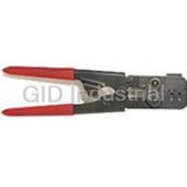
Press Tool
0851700006
Part Number
0851700006
Price
Request Quote
Manufacturer
MOLEX
Lead Time
Request Quote
Category
Fasteners, Hardware and Fluid Transfer » Hardware Tools
Specifications
Manufacturer
Molex
Manufacturers Part #
0851700006
Industry Aliases
85170-0006, 851700006
Sub-Category
Hardware Tools
Factory Pack Quantity
1
Datasheet


Extracted Text
Tooling Manual OMNIGRID INSTALLATION TOOLING For The Molex OmniGrid Connector 85101, 85103, 85105, 85107, 85109, 85125, 85127, 85151, 85153, 85155, 85157, 85159, 85170, & 85301 Series and 85171-0009 * DESCRIPTION * OPERATION * MAINTENANCE Doc. No OMNIGRID99.lwp Release Date 2000/08/29 Revision: Initial Release Revision Date: WARNING NEVER OPERATE, SERVICE OR ADJUST THIS DEVICE WITHOUT PROPER INSTRUCTION AND WITHOUT FIRST READING AND UNDERSTANDING THE INSTRUCTIONS IN THIS MANUAL. WORK SAFELY AT ALL TIMES FOR SERVICE, CONTACT YOUR LOCAL MOLEX SALES OFFICE MOLEX APPLIC ATION TOOLING GROUP 1150 E. DIEHL ROAD NAPERVILLE, ILLINOIS 60563 (630) 969-4550 FAX: (630) 505-0049 OMNIGRID TOOLING TABLE of CONTENTS SECTION 1 General Description 2 Installation and Operation 3 Maintenance & Problem Checklist 4 Available Tooling 5 Glossary APPENDIX A Assembly Drawings and Bills of Materials For Standard Male & Female Connector Press In Tooling B Instruction Sheets For Repair And Specialty Tools C Assembly Drawings and Bills of Materials and Instruction Sheets for Custom Tools D Product Specificatons E Terms & Conditions SECTION 1 GENERAL DESCRIPTION Page 1.1 DESCRIPTION . . . . . . . . . .. . . . . . . . . . . . . . . . . . 1-2 1.2 FEATURES . . . . . . . . . . . . . . . . . . . . . . . . . . . . . . 1-2 1.3 TECHNICAL SPECIFICATIONS . . . . . . . . . . . . . . 1-2 1.4 DELIVERY CHECK. . . . . . . . . . . . . . . . . . . . . . . . 1-3 1.5 TOOLS . . . . . . . . . . . . . . . . . . . . . . . . . . . . . . . . . . 1-3 1.6 PRESS REQUIREMENTS . . . . . . . . . . . . . . . . . . . 1-3 1-1 1 GENERAL DESCRIPTION TABLE 1-1A MALE TOOLING APPLICABLE CONNECTORS 1.1 DESCRIPTION Connector Description Series The Molex Omnigrid Tooling is 85101-xxxx 1 SU Omnigrid Header designed to press Molex Omnigrid connectors into printed circuit boards. 85103-xxxx 2 SU Omnigrid Header See Table 1 for applicable connectors. 85105-xxxx 4 SU Omnigrid Header The operator sets a pc board in the tool, and positions a connector on the 85107-xxxx 9 SU Omnigrid Header board. Then, depending on the 85109-xxxx 10 SU Omnigrid Header connector, places the tool in the connector (male connectors) and 4 SU Header with Power 85125-xxxx lowers the press ram onto the tooling Terminals or they lower the ram, with the upper 9 SU Header with Power tooling attached (right angle female 85127-xxxx Terminals connectors), onto the connector and 85151-xxxx 1 SU Lubricated Header press it into the board. For straight female connectors the connector is 85153-xxxx 2 SU Lubricated Header loaded into the tool which is then placed into the press for insertion. 85155-xxxx 4 SU Lubricated Header Male and straight female connectors 85157-xxxx 9 SU Lubricated Header require a customer supplied support. 85159-xxxx 10 SU Lubricated Header 1.2 FEATURES 85301-xxx Other Omnigrid Headers § Female insertion tooling very flexible, lower tooling components easily TABLE 1-1B FEMALE TOOLING interchanged to accommodate most APPLICABLE CONNECTORS any combination of connectors. Connector Description (Right Angle § Complete line of repair tools. Series Unless Otherwise Noted) 85100-xxxx 1 SU Female Connector 1.3 TECHNICAL SPECIFICATIONS 85102-xxxx 2 SU Female Connector 85104-xxxx 4 SU Female Connector See the individual tool sheets in Appendix A for tooling dimensions, 85106-xxxx 9 SU Female Connector weights. 85108-xxxx 10 SU Female Connector . 4 SU Female Conn. with 85124-xxxx Power Terminals 9 SU Female Conn. with 85126-xxxx Power Terminals (continued) 1-2 TABLE 1-1B (con’t) FEMALE TOOLING Letter Description Dimension (min) APPLICABLE CONNECTORS A Upper Platen 51mm X 102mm X Connector 25.4mm (2 in. X 4 Description Series in. X 1 in.) 1 SU Lubricated Female 85150-xxxx B Opening 89mm (3.5 in.) Connector 2 SU Lubricated Female 85152-xxxx C Throat 150mm (6 in.) Connector 4 SU Lubricated Female Force 66N (15 lbs) per 85154-xxxx Connector pin 9 SU Lubricated Female 85156-xxxx Connector 10 SU Lubricated Female 85158-xxxx Connector 4 SU Straight Female 85171-0009 Connector Other Omnigrid Female 85301-xxxx Connectors 1.4 DELIVERY CHECK Carefully remove the tooling from its shipping container and check to confirm that the tooling matches the purchase order and that a copy of Fig. 1-1 Instruction Manual P.N. OMNIGRID99 PRESS DIMENSIONS is included. Also check for any damage. 1.6.1 Molex Presses 1.5 TOOLS A Molex offers four (4) presses suitable metric hex wrench set may be needed for one or more of these applications to install these tools. (See Fig. 1-2, 1-2A, 1-3 & 1-4). They are: 1.6 PRESSES 62200-9200 8-ton Omnigrid Pneumatic Press (For These tools are designed to be used in Female Connector Tooling) a variety of presses depending on the tooling If a flat platen press is used, it should meet the following requirements 62201-3800 8-ton Pneumatic Flat Platen Press (For Header (Refer to Fig. 1-1): Tooling) 1-3 Fig. 1-2A Fig. 1-2 MOLEX STANDARD (8-TON) FLAT MOLEX (8-TON) OMNIGRID PLATEN PNEUMATIC PRESS PNEUMATIC PRESS 62200-9200 62201-3800 62200-6400 16-ton Electric Flat Platen Press 62200-6100 Molex Standard Manual Press (P.N. 11-31-6356) with OmniGrid Modification Kit (P.N. 62200-7500). This press will only do up to and including 4SU connectors. See Instruction Manuals 62200-9299 & 62201-3899 for further details on the 62200-9200 press and the 62201-3800 press respectively. Fig. 1-3 See Instruction Sheet 62200-6199 for MOLEX STANDARD (15-TON ) FLAT further details on the 62200-6100 PLATEN ELECTRIC PRESS 62200-6400 1-4 Fig. 1-4 OMNIGRID MOLEX STANDARD MANUAL PRESS WITH MODIFICATION KIT Omnigrid manual press. (Copy in Appendix A.) 1-5 SECTION 2 INSTALLATION AND OPERATION Page 2.1 INSTALLATION . . . . . . . . . . . . . . . . 2-3 2.2 ADJUSTMENTS . . . . . . . . . . . . . . . . 2-3 2.3 PC BOARD SUPPORT . . . . . . . . . . . . 2-4 2.4 OPERATION . . . . . . . . . . . . . . . . . 2-5 2.5 INTERCHANGING LOWER TOOLING COMPONENTS . . . . . . . . . . . . . . . . 2-7 2-1 Fig. 2-1 OVERALL VIEW OF COMPLETE FEMALE DIE ASSEMBLY IN THE MOLEX OMNIGRID PNEUMATIC PRESS 2-2 2 INSTALLATION AND OPERATION different set of holes depending on how much the pc board size has changed.) 2.1 INSTALLATION 8. Position a pc board in the tooling. 9. Adjust the support rail so that it 2.1.1 Installing Lower Female Insertion supports the forward end of the pc Tooling In An Existing Die Set board (See Fig. 2-12). If the customer purchases a different 2.2 ADJUSTMENTS lower tooling assembly, to be used in a die set with upper tooling that he already possesses. This is done as follows: 1. Loosen the two (2) locking screws on the front of the die set lower plate. 2. Remove the present lower tooling assembly by lifting it up until the dowel pins clear and then bringing it forward. 3. Locate the two dowels, on the new lower tooling, over the two holes in the die base and lower the tooling onto the base. 4. Tighten the two locking screws. 2.1.2 Installing A Complete Die Assembly Fig. 2-2 Into A Molex Ominigrid Press DIE SET IN PRESS 2.2.1 Press Stroke Adjustment (For 1. Remove the die adaptor from the Header Tooling) press or from another die set. (See Fig. 2-2). Most presses have some means of 2. Back out the locking set screw in the adjusting the stroke, please refer to the upper die block. appropriate manual (for the press 3. Insert the die adaptor into the hole being used) for press stroke provided for it in the upper die block. adjustments. 4. Tighten the locking set screw. 5. Set the die set on the press plate 2.2.2 PC Board Thickness (For Female and slide it back so that the die Tooling) adaptor goes into the slot in the upper press adaptor plate and On the top rear of the lower tooling against the stop. mounting block is a thin removal bar. 6. Tighten the knob on the die clamp to This bar acts as a positive stop for the lock the die set into the press. press ram. The thickness of this bar 7. Loosen the four (4) support rail should be such that when the press ram locking screws. (It may be necessary stops in the down position, the bottom to relocate these screws in a 2-3 of the connector is flush to .155 mm fixture. The female insertion tooling has (,006 in.) above the surface of the pc the support and locators built in. board. See Fig. 2-3 and 2-4. 2.3.1 Universal Support Molex offers two (2) “universal” support blocks, a 116 mm (4.56 in.) long one (P.N. 85189-0189), and a 266 mm (10.5 in.) long one (P.N. 85189-0191). These work for prototyping but they have no locating feature and are therefore slow to use. 2.3.2 Alternate Method A very functional support fixture can be easily constructed using the following technique: 1. Locate a suitable piece of material for the support. It should the same size or a little larger than the printed circuit board to be used. While aluminum could be used, a rigid Fig. 2-3 nonconductive material such as a RAM STOP BAR phenolic is preferred. (A stack of 2.3 PC BOARD SUPPORT (REQUIRED scrap pc boards of suitable size could be fastened together and used). 2. Obtain a scrap pc board like the ones to be assembled. Attach this board to the material from step 1. 3. Using an oversize drill bit, drill through each hole where a pin from the connector(s) will go. Drill deep enough into the lower material to be certain the pins do not bottom out Fig. 2-4 when inserted (at least 5 mm [.020 RAM SETTING in.] deep). FOR HEADER INSTALLATION) 4. Locate two (2) holes on the pc board to use as locating points. Drill for Pressing an Omnigrid header into a and mount suitably sized dowel pins printed circuit board takes in these two locations on the support considerable force, therefore, the fixture. board must be supported during the insertion to avoid damage to the pc board and/or its components. Some means of locating the board on the 2-4 2.4 OPERATION 2.4.1 Header Insertion 1. Carefully locate the header on the printed circuit board and start in by hand. (See Fig. 2-5 & 2-6) Fig. 2-7 PC BOARD ON SUPPORT FIXTURE Fig. 2-5 LINING UP HEADER Fig. 2-8 INSERTION TOOL IN POSITION Fig. 2-6 HEADER STARTED INTO PC BOARD 2. Locate the preloaded board onto the support fixture. (See Fig. 2-7) 3. Locate the proper header insertion tool in the header, carefully checking alignment. (See Fig. 2-8) 4. Position the loaded support fixture under the press platen. 5. Cycle the press. 6. Remove the support fixture from under the press. 7. Remove the insertion tool from the Fig. 2-9 header. TOP TOOL IN PLACE 8. Remove the assembled pc board (For Reference Only, See Note) from the fixture. 2-5 NOTE: There are two header top tool (P.N. KNOB (REMOVE 85189-0294 & 85189-03090 that are FOR FLAT ROCK required for one of the European PRESS) presses. Fig. 2-9 shows this tool in place. It would be attached to the press ram and move downand up with the ram. Fig. 2-11 VERTICAL FEMALE INSERTION TOOL 85170-0002 2. A connector is loaded into the tool as shown in Fig. 2-12. The tool is keyed so that the housing will only go Fig. 2-10 in one way. CONNECTOR IN TOOLING 3. Place the printed circuit board in the support fixture (provided by the customer, (See Section 2.3). 2.4.2 Right Angle Female Connector 4. Locate the support fixture under the Insertion press ram. 1. Load a connector of the proper size INSERTION TOOL into the nest in the lower tooling. (See Fig. 2-10) 2. Position a printed circuit board over the locating pins and lower it onto the connector and the support rail. (See Fig. 2-13) 3. Cycle the press. 4. Remove the loaded pc board by lifting it up off the locating pins then bringing it forward. 2.4.3 Vertical Female Connector Insertion CONNECTOR 1. If there is a knob on top of the tool Fig. 2-12 (See Fig. 2-11), remove it. TOOL (85170-0002) AND CONNECTOR 2-6 5. Position the insertion tool with the 2.5 INTERCHANGING LOWER connector in it, on the pc board TOOLING COMPONENTS making sure the terminals are Both the European and the u.s. properly located in the appropriate versions of the OmniGrid tooling for holes. pressing in right angle female 6. Cycle the press. connectors is designed to allow 7. Remove the assembly from under interchanging of components to the press ram. accommodate a wide variety of connector arrangements. For example: 8. Slide the tool out of the connector. the customer currently owns a 9. Remove the completed insertion 62201-2300 4SU Complete from the support fixture. Fig. 2-13 LOCATING PC BOARD IN FIXTURE 2.4.4 Other Die Assembly and he wants to press in Tools a 1SU connector. All that is required is There are a variety of other tools, removing several pieces and relocating special assembly tool, repair tools etc. the remaining ones. The operation of these tools is This will be explained in more detail explained on the instruction sheets for later. these tools, copies of which are found A 4SU press will accommodate 1SU in Appendix A through 4SU tooling while a 10SU 2-7 press will accommodate 1SU through NOTE: The insertion tooling, when 10SU tooling. assembled, should be approximately in Section 4.4 has two lists showing all the the center of the mounting rail. U.S. lower tooling components and all 6. Put the rail back into the lower die the European components and which of plate and tighten the two locking them is required for any connector. screws. Also in Appendix A are assembly drawings of each of the tools. EXAMPLE TWO: Changing a 2SU setup to a To change from one size to another will 4SU. be easily seen with the following 1. Doing the same comparison as we examples. did in step 1 of Example One we get the following results: EXAMPLE ONE: Using the example above 2SU 4SU of changing a U.S. 4SU setup to a 1SU (1) 62201-1901 (1) 62201-1901 do the following steps: 17..5mm Comb 17..5mm Comb 1. Look at the U.S. table in Section 4.4 and compare a 4SU assembly (1) 62201-1902 to a 1SU assembly. A 1SU will 25mm comb require the following parts: (1) 62201-1909 (1) 62201-1901 17.5mm comb 42.4 holdown plate (1) 62201-1910 17.3 Plate (1) 62201-1904 (1) 62201-1911 Left End Block --- 57.5mm comb (1) 62201-1912 Right End Block (1) 62201-1919 4SU Mounting (1) 62201-1908 --- 67.3 holdown plate Rail. All other parts are common to all sizes. 2. The first comb matches, however The 4SU has at least one of all the second comb and the holdown these parts. Therefore no new parts plate do not match and therefore are required. need to be ordered. 2. Loosen the two locking screws on 3. Once these parts have arrived, the front of the lower die plate. simply follow steps 2 through 6 in 3. Remove the lower mounting rail with the above example except use the all the pieces form the lower die 4SU lower tooling assembly plate. drawing 62201-3000 4. Remove all the parts from the NOTE: The 1SU, 2SU, 2.3SU & 4SU tooling mounting rail laying aside those will work in the 10SU die set. parts required for the 1SU assembly. 5. Now go to the 62201-2700 1SU lower tooling assembly drawing in Appendix A and reassemble the necessary parts to the mounting rail per the drawing. 2-8 SECTION 3 MAINTENANCE, PERISHABLE PARTS, SPARE PARTS AND PROBLEM CHECKLIST Page 3.1 MAINTENANCE . . . . . . . . . . . . . . . . . . . . 3-2 3.2 PERISHABLE PARTS . . . . . . . . . . . . . . . . . 3-2 3.3 SPARE PARTS . . . . . . . . . . . . . . . . . . . . 3-2 CHART 3.1 MAINTENANCE RECORD . . . . . . . . . . 3-3 3.4 PROBLEM CHECKLIST . . . . . . . . . . . . . . . . 3-4 3-1 3 MAINTENANCE, PERISHABLE considered perishable. Individual PARTS, SPARE PARTS AND pieces may be ordered as required. See Section 4 for Part Numbers. PROBLEM CHECKLIST 3.3 SPARE PARTS For most of the tooling refer to the instruction sheets in the Appendixes. These are moving or otherwise The following instructions refer to the right angle female press in tooling. functioning parts that may be damaged or otherwise cease to function correctly. Molex suggests that the 3.1 MAINTENANCE customer may want to keep some or all (Right Angle Female Press In of these parts on hand to reduce Tooling Only) downtime. There are no recommended spare parts for the tooling, however the 3.1.1 Cleaning press will have recommended spare so it is important to check the proper At least once a day the tooling should press manual for its recommended be cleaned with a soft brush to remove spare parts. plating dust and other debris. CAUTION: It may be necessary to use compressed air to clean out some of the small holes in the tooling. However, extreme caution must be exercised when doing this as compressed air can cause chips to wedge in the tooling and/or come flying out at the operator. Proper safety glasses should be worn when using compressed air. The press should also be cleaned of all dust and debris. 3.1.2 Lubrication Some of the bearings or bushings on the die sets may require a small amount of lubricant with Teflon such as Permatix “Super Lube” #82329 monthly. The press will also require lubrication usually once a month. See the press instruction manual for press lubrication requirements. 3.2 PERISHABLE PARTS These are parts that contact the product and will wear over time. All components of this tooling are 3-2 CHART 3.1 PREVENTIVE MAINTENANCE DAILY: Clean, See Section 3.1. MONTHLY: Lubricate press, See Section 3.2. CHECK SHEET MONTH YEAR MON TUE WED THU FRI SAT SUN WEEK (Daily) 1 Clean WEEK 2 WEEK (Check box 3 when done) WEEK 4 WEEK 5 (Monthly) Lubricate (Sample Chart may be copied for mounting.) Schedule should be adjusted up or down depending on usage. It is Molex’s recommendation that a log of preventive maintenance be kept with tool. 3-3 3.4 PROBLEM CHECKLIST PROBLEM POSSIBLE CAUSE SOLUTION 1. Header contacts are being 1. The connector is not 1. Check connector damaged. oriented or positioned orientation and position correctly. and correct. 2. There is debris in the 1. Inspect and clean the tooling. tooling thoroughly 3. Press ram stroke too long. 1. See Section 2.1 and the press manual and reset the press stroke. 4. Shipping Damage. 1. Inspect connectors and packaging. 2. The connectors are not 1. Press ram stroke is too 1. See Section 2.1 and the being fully seated in the short. press manual and pc board. reset the press stroke. 3. Press problems 1. See Trouble Shooting Section of press instruction manual. 3-4 SECTION 4 AVAILABLE TOOLS Page 4.1 ASSEMBLY TOOLS . . . . . . . . . . . . . 4-2 4.2 CUSTOMER SPECIALS . . . . . . . . . . . 4-6 4.3 REPAIR TOOLS . . . . . . . . . . . . . . . 4-9 4.4 LOWER TOOLING COMPONENTS . . . . . 4-11 4-1 SECTION 4.1 AVAILABLE ASSEMBLY TOOLING 4.1.1 FEMALE CONNECTOR PRESS TOOLING COMPLETE DIE SET COMPLETE LOWER EUROPEAN WITH UPPER CONNECTOR U.S. DIE TOOLING DIE TOOLING ASSEMBLY U.S. ONLY ASSEMBLY U.S. ONLY FEMALE 85100-XXXX 1 SU 62201-2000 * 85189-0000 62201-3400 62201-2700 85150-XXXX 85102-XXXX 2 SU 62201-2100 * 85189-0012 62201-3400 62201-2800 85152-XXXX 2.3 SU 85301-XXXX 62201-2200 * 85189-0050 62201-3400 62201-2900 85104-XXXX 4 SU 85124-XXXX 62201-2300 * 85189-0024 62201-3400 62201-3000 85154-XXXX 5.4 SU 85301-XXXX 62201-2400 * 85189-0062 62201-3500 62201-3100 85106-XXXX 9 SU 85126-XXXX 62201-2500 * 85189-0036 62201-3500 62201-3200 85156-XXXX 85108-XXXX 10 SU 62201-2600 * 85189-0048 62201-3500 62201-3300 85158-XXXX 4 SU 85171-0009 N.A. 85710-0002 N.A. N.A. * These assemblies can be ordered complete, or as separate upper and lower tooling assemblies. See Section 4.4 for additional details. See also Appendix A1 & A2 for assembly drawings and specifications. 4-2 4.1.2 VERTICAL FEMALE CONNECTOR PRESS TOOLING EUROPEAN PRESS U.S. PRESS TOOL CONNECTOR TOOL ORDER NO. ORDER NO. 4SU X 22 mm HIGH 85170-0001 N.A. 4SU X 18.5 mm HIGH 85170-0002 N.A. 2SU X 22 mm HIGH 85170-0003 N.A. 2SU X 18.5 mm HIGH 85170-0004 N.A 1SU X 22 mm HIGH 85170-0005 N.A. 1SU X 18.5 mm HIGH 85170-0006 N.A. 1SU RECEPTACLE 85189-0804 62201-6400 See Appendix A3 for Instruction Sheets with drawings and dimensions. 4.1.3 MALE CONNECTOR PRESS TOOLING CONNECTO HEADER TOP TOOL HEADER PRESS R ORDER NO. TOOL ORDER NO. (HEADER) 85101-XXXX 1 SU 85189-0294 85189-0206 85151-XXXX 85103-XXXX 2 SU 85189-0294 85189-0218 85153-XXXX 2.3 SU 85189-0294 85189-0256 85105-XXXX 4 SU 85125-XXXX 85189-0294 85189-0220 85155-XXXX 5.4 SU 85189-0309 85189-0268 85107-XXXX 9 SU 85127-XXXX 85189-0309 85189-0232 85157-XXXX 85109-XXXX 10 SU 85189-0309 85189-0244 85159-XXXX There are no U.S. equivalent tools at this time. See Appendix A4 for Instruction Sheets with drawings and dimensions. 4-3 4.1.4 RIGHT ANGLE HEADER PRESS TOOLING This is a list of the complete die sets with tooling for pressing in the various sizes of OmniGrid right angle headers. If the owner of any one of these tools needs to press in a different size, it is not necessary to purchase another complete assembly. Simply purchase the necessary change parts and reassemble to suit. See drawing no. SD-85178-002 in Appendix A5 for details. HEADER ORDER NO. SIZE 1SU Std. 85178-0000 2SU Std. 85178-0001 4SU Std. 85178-0002 5.4SU Std. 85178-0003 1SU I/O 85178-0004 2SU I/O 85178-0005 4SU I/O 85178-0006 5.4SU I/O 85178-0007 4-4 4.1.5 CRIMP TOOLING Used For ORDER NO. DESCRIPTION Part No. A hand tool for crimping Omnigrid Crimp 69008-1050 85311-0440 Contacts are on small reels. A hand tool for crimping Omnigrid Crimp 69008-1051 85311-0438 contacts to AWG 22-26 wire Contacts are on small reels. 747579-X A kit that goes into the Molex Standard Manual to 11-39-0290 or crimp ferrules to the OmniGrid 1SU and 2SU 747580-X outer shells. See manual for AM63243 A Molex standard ”Mini-Mac” applicator with 69037-1093 85311-0438 tooling for crimping the OmniGrid contacts to AWG 22-26 wire. The perishable tooling kit for a “Mini-Mac” 69037-2093 85311-0438 applicator for crimping the OmniGrid contacts to AWG 22-26 wire. A Molex standard ”Mini-Mac” applicator with 69037-1094 85311-0440 tooling for crimping the OmniGrid contacts to AWG 26-30 wire. The perishable tooling kit for a “Mini-Mac” 69037-2094 85311-0440 applicator for crimping the OmniGrid contacts to AWG 26-30 wire. See Appendix B for instruction sheets for these tools (unless otherwise noted). 4-5 4.2 CUSTOMER SPECIAL ASSEMBLY TOOLS These tools are designed for a specific customer’s special application. CONNECTOR U.S. ORDER GERMAN DESCRIPTION N0. NO. ORDER NO. This is a complete press die 4SU assembly for assembling two (2) 4SU N.A. 85189-0490 851X4-XXXX connectors. 9SU This is a complete press die 851X6-XXXX assembly for assembling a special N.A. 85189-0608 with 2 P.M. 9SU connector with 2 power modules. 4SU This is a complete press die assembly for assembling a 4SU N.A. 85189-0610 851X4-XXXX connector with 2 power modules with 2 P.M. 4SU This is a complete press die 851X4-XXXX assembly for assembling a 4SU N.A. 85189-0622 with 2 P.M. connector with 4 power modules. This is a header press tool for 4SU assembling two (2) 4SU headers. N.A. 85189-0488 851X5-XXXX Use with 85189-0309 header top tool. This is a header press tool for 2.3SU assembling three (3) 2.3SU headers. N.A. 85189-0505 Use with 85189-0309 header top tool. This is a special lower tooling assembly for inserting an Omnigrid 11SU connector assembly into a Nortel CE 62201-6800 N.A. board with components. It is used in the 62201-6700 die set with upper tooling. This is a special lower tooling assembly for inserting an Omnigrid connector assembly into a Nortel SM 11SU 62201-6900 N.A. board with components. It is used in the 62201-6700 die set with upper tooling. See Appendix C for assembly drawings and bills of materials on these tool assemblies. 4-6 4.2 CUSTOMER SPECIAL ASSEMBLY TOOLS (con’t) CONNECTOR U.S. ORDER GERMAN DESCRIPTION NO. NO. ORDER NO. This is a special lower tooling assembly for inserting an Omnigrid connector assembly into a Nortel 0C3 11SU 62201-7000 N.A. board with components. It is used in the 62201-6700 die set with upper tooling. This is a special lower tooling assembly for inserting an Omnigrid connector assembly into a Nortel RM 11SU 62201-7100 N.A. pc board with components. It is used in the 62201-6700 die set with upper tooling. This is a custom lower tooling assembly for inserting a 9SU connector with two coding blocks into 11SU 62201-0400 N.A. a Qualcom printed circuit board. It is used in the Molex 62201-6900 11Su die set with upper tooling. This is a custom tool designed to A special mix press a combination of OmniGrid and of OmniGrid HDM connectors into a printed circuit 62201-8400 N.A. and HDM board. It is designed to be used in the Molex 62202-8200 flat platen press or connectors equivalent. This is a special version of the standard 10SU die set for Sanmina 10SU 62201-4500 N.A. Elastic Networks tooling. The upper tooling comes with each tooling set. This is a custom set of tooling to press in a combination of OmniGrid Mix of (2) 1 Su right angle female connectors for the 62201-4600 and (1) 4 SU Sanmina Elastic Networks “Modem Card”. It goes into 62201-4500. This is a custom set of tooling to press in a combination of OmniGrid Mix of (1) 1SU right angle female connectors for the 62201-4700 N.A. and (1) 4 SU Sanmina Elastic Networks “Switch Card”. It goes into 62201-4500. These tools are designed for a specific customer’s special application. See Appendix C for assembly drawings and bills of materials on these tool assemblies. 4-7 4.2 CUSTOMER SPECIAL ASSEMBLY TOOLS (con’t) CONNECTOR U.S. ORDER GERMAN DESCRIPTION NO. NO. ORDER NO. This is a custom lower tooling set to press in a special arrangement of two (2) 1 SU Omnigrid connectors for the (2) 1SU 62201-4900 N.A. Sanmina Elastic Networks “Filter Card. It is used in the 62201-4500 die set. This is a custom set of tooling to Mix of (4) press in a combination of OmniGrid Power right angle female connectors for the 62201-5000 N.A. Modules & (1) Sanmina Elastic Networks “Power 1 SU Card”. It goes into 62201-4500. This is a custom set of backplane Mix of (2) 1 Su tooling to press in a combination of 62201-5100 N.A. and (1) 4 SU OmniGrid headers for the Sanmina Elastic Networks “Modem Card”. Mix of (4) This is a custom set of backplane Power tooling to press in a combination of 62201-5200 N.A. Modules & (1) OmniGrid headers for the Sanmina 1 SU Elastic Networks “Power Card”. This is a custom set of backplane Mix of (1) 1SU tooling to press in a combination of 62201-5300 N.A. and (1) 4 SU OmniGrid headers for the Sanmina Elastic Networks “Switch Card”. This is a custom set of backplane tooling to press in a combination of (2) 1SU 62201-5500 N.A. OmniGrid headers for the Sanmina Elastic Networks “Filter Card”. These tools are designed for a specific customer’s special application. See Appendix C for assembly drawings and bills of materials on these tool assemblies. 4-8 AVAILABLE REPAIR TOOLS There are a variety of tools designed for repairing printed circuit boards with Omnigrid connectors, where a connector has been damaged or installed incorrectly. The following is a list of these tools. Instruction Sheets for these tools can be found in Appendix B. Description Function Order No. For inserting replacement pins into an Omnigrid Pin Insertion Tool 85189-0402 connector Used to remove Omnigrid pins from the Pin Retention Tool 85189-0414 backpanel. Applied to lock (clockwise) or unlock (ccw) a rear Turn Tool shroud for cable connectors to the tails of a 85189-0426 pressed in Omnigrid header. Applied to lock (clockwise) or unlock (ccw) a rear shroud for cable connectors to the tails of a Multiple Turn Tool 85189-0438 pressed in Omnigrid header. One operation locks in all plates of a 1 SU unit. Female Contact Ejection Used to remove a single female contact from an 85189-0529 Tool Omnigrid connector. Used to extract a terminated crimp contact from Crimp Terminal a cable connector housing. The tool is applied 85189-0546 Extraction Tool from the front connector face. Used to insert terminated crimp contacts into the Crimp Terminal insertion cable connector housing when using AWG 26 85189-0658 Tool wire or thinner. Female Coding Box Used to install the OmniGrid female coding box 85189-0751 Installation Tool or service contact receptacle (P.N. 85323-0000. This tool is used to install an OmniGrid male Male Coding Key coding or Service contact male with back coding 85189-0763 Installation Tool device (P.N. 85323-0036 or 85323-0074 with 85323-01XX 0r 85323-07XX). This tool is used to install the OmniGrid female Female Coding Key coding key or card coding device (P.N. 85189-0775 Installation Tool 85323-0012, 85323-0024 or 85323-0062) 4-9 AVAILABLE REPAIR TOOLS (con’t) Description Function Order No. Used to push out the plastic pegs of the female Punch (2.4 mm) 85999-2320 connector housing. Used to push out the plastic pegs of the female Punch (1.8 mm) 85999-2321 connector housing. 4-10 U.S. LOWER TOOLING COMPONENTS If you already own the proper die set with upper tooling and any lower tooling assembly with the correct mounting rail, simply compare the combs, holdown plates, end blocks, etc. you have with the requirements for the new tooling, and order only the parts needed to complete the new tooling assembly. See Appendix A for tooling assembly drawings. DESCRIP- ORDER NO. TION 62201-3400 Die Set Short (Ref) 1 1 1 1 62201-3500 Die Set Long (Ref) 1 1 1 62201-0307 Dowel 2 2 2 2 2 2 2 62201-1901 Comb (17.5 mm) 1 1 1 2 4 4 62201-1902 Comb (25 mm) 1 2 1 62201-1903 Comb (27.5 mm) 1 1 62201-1904 Comb (57.5 mm) 1 1 2 2 62201-1905 Comb (30 mm) 62201-1906 Comb (32.5 mm) 1 62201-1907 Holdown Plate (92.3 mm) 62201-1908 Holdown Plate (67.3) 1 1 3 2 62201-1909 Holdown Plate (42.3) 1 1 1 2 62201-1910 Holdown Plate (17.3) 1 1 62201-1911 Left Endblock 1 1 1 1 1 62201-1912 Right Endblock 1 1 1 1 1 1 1 62201-1913 Spacer (2.5 mm) 1 2 2 62201-1914 Locator Pin (2.0 mm) 1 1 1 1 1 1 1 62201-1915 Locator Pin (2.5 mm) 1 1 1 1 1 1 1 62201-1916 Locator Pin (2.8 mm) 62201-1917 Locator Pin (3.5 mm) 62201-1918 10 SU Mounting Rail 1 1 1 62201-1919 4 SU Mounting Rail 1 1 1 1 62201-1920 Stop Pad (1.6 mm) 1 1 1 1 1 1 1 62201-1921 Special Lt. Endblock 1 62201-1922 Special Lt. Endblock 1 62201-1923 Spacer (5.0 mm) 2 2 2 2 2 2 2 62201-1924 Long Riser Block Spec. For TOX Press 62201-1925 Short Riser Block Spec. For TOX Press 4-11 1SU 62201-2700 2 SU 62201-2800 2.3 SU 62201-2900 4 SU 62201-3000 5.4 SU 62201-3100 9 SU 62201-3200 10 SU 62201-3300 EUROPEAN LOWER TOOLING COMPONENTS If you already own the proper die set with upper tooling and any lower tooling assembly with the correct mounting rail, simply compare the combs, holdown plates, end blocks, etc. you have with the requirements for the new tooling, and order only the parts needed to complete the new tooling assembly. See Appendix A for tooling assembly drawings. DESCRIP- ORDER NO. TION N.A. Die Set Short (Ref) 1 1 1 1 N.A. Die Set Long (Ref) 1 1 1 1 1 1 1 85919-0018 Comb (17.5 mm) 1 1 2 2 4 4 4 1 4 85919-0019 Comb (25 mm) 1 2 1 85919-0020 Comb (27.5 mm) 1 1 85919-0021 Comb (57.5 mm) 1 1 2 2 2 1 1 2 85919-0056 Comb (30 mm) 85919-0057 Comb (32.5 mm) 1 85919-0027 Holdown Plate (67.3) 1 1 3 2 2 1 1 3 85919-0028 Holdown Plate (42.3) 1 1 1 2 85919-0055 Holdown Plate (17.3) 1 1 2 1 1 85919-0022 Left Endblock 1 1 1 1 1 1 1 1 85919-0023 Right Endblock 1 1 1 1 1 1 1 1 1 1 1 85919-0082 Special Lt. Endblock 1 1 85919-0083 Special Lt. Endblock 1 85919-0029 Spacer (2.5 mm) 1 2 2 3 2 85919-0024 Locator Pin (2.0 mm) 1 1 1 1 1 1 1 1 1 1 1 85919-0025 Locator Pin (2.5 mm) 1 1 1 1 1 1 1 1 1 1 1 85919-0126 Locator Pin (3.5 mm) 85919-0058 Comb, Special 1 2 85919-0059 Comb, Special 1 4-12 1SU 85189-0000 2 SU 85189-0012 2.3 SU 85189-0050 4 SU 85189-0024 5.4 SU 85189-0062 9 SU 85189-0036 10 SU 85189-0048 2.4SU 85189-0490 4SU + 2 85189-0610 4SU + 4 85189-0622 9SU+2 85189-0608 SECTION 5 GLOSSARY OF TERMS OmniGrid Molex’s 2.5mm connector family for printed circuit boards and backplanes conforming to IEC 1076-4-100. It is a 5-row backplane connector system with female contacts on the module and pins on the backplane. PC Board Short for printed circuit board. Pin Male electrical contact or terminal. Support A device used to locate and support a printed circuit board when a header is Fixture being pressed into it. Since each pc board application is different, these supports are usually supplied by the customer. See Section 2.3 for construction details. Die Set A standard die set consisting of an upper plate, a lower plate, 2 die rods and 2 sets of bearings and/or bushings. APPENDIX A ASSEMBLY DRAWINGS & BILLS OF MATERIALS FOR STANDARD MALE AND FEMALE PRESS IN TOOLS Page A1 U.S. RA FEMALE PRESS IN TOOLS . . . . . . . . . A-2 A2 EUROPEAN RA FEMALE PRESS IN TOOLS. . . . . A-19 A3 VERTICAL FEMALE PRESS IN TOOLS . . . . . . . A-27 A4 MALE PRESS IN TOOLS . . . . . . . . . . . . . . A-34 A5 RIGHT ANGLE HEADER PRESS IN TOOLS . . . . . A-39 A-1 APPENDIX A1 U.S. RIGHT ANGLE FEMALE CONNECTOR PRESS IN TOOLING COMPLETE DIE DIE SET WITH LOWER TOOLING CONNECTOR ASSEMBLY UPPER TOOLING ASSEMBLY 85100-XXXX 1SU 62201-2000 62201-3400 62201-2700 85150-XXXX 85102-XXXX 2SU 62201-2100 62201-3400 62201-2800 85152-XXXX 2.3SU 85301-XXXX 62201-2200 62201-3400 62201-2900 85104-XXXX 4SU 85124-XXXX 62201-2300 62201-3400 62201-3000 85154-XXXX 5.4SU 85301-XXXX 62201-2400 62201-3500 62201-3100 85106-XXXX 9SU 85126-XXXX 62201-2500 62201-3500 62201-3200 95156-XXXX 85108-XXXX 10SU 62201-2600 62201-3500 62201-3300 85185-XXXX These tools can be bought as complete assemblies, separate upper and lower tooling assemblies or lower tooling components for reduced cost in going from one size to another. See Section 2-7, Section 4 and the Assembly Drawings following for details. A-2 62201-2000 OmniGrid 1 SU Complete Die Assembly BILL OF MATERIALS 62201-2000 Item Order No. Description Req’d. 1 62201-3400 Assembly, Die Set with Upper Tooling 1 2 62201-2700 Assembly, Lower Tooling 1 See the main manual, Section 1.7, for details of the Die Set Assembly. If you already own the 62201-3400 Die Set Assembly, the Lower Tooling Assembly can be ordered separately. Or if you already own any small die Lower Tooling Assembly, the Combs and Holdown Plates necessary to make this Lower Tooling Assembly can also be ordered separately. See the next page for the Lower Tooling Assembly details. This tooling weights approximately 5.4 kg (12.0 lb) and will do about 200 assemblies per hour depending on operator skill and press speed. A-3 62201-2700 1 SU LOWER TOOLING ASSEMBLY BILL OF MATERIALS 62201-2700 Item Order No Description Req’d. 1 62201-1914 Pin, Locator (2.00 mm) 1 2 62201-1901 Comb (17.5 mm Long) 1 3 62201-1915 Pin, Locating (2.5 mm) 1 4 62201-1920 Pad, Stop (1.6 mm) 1 5 62201-1919 Rail, Mounting (4 SU) 1 6 62201-0307 Dowel 2 7 62201-1912 Endblock, Right 1 8 62201-1910 Plate, Holdown (17.3 mm) 1 9 62201-1923 Spacer, (5.0 mm) 2 10 62201-1911 Endblock, Left 1 A-4 62201-2100 OmniGrid 2 SU Complete Die Assembly BILL OF MATERIALS 62201-2100 Item Order No. Description Req’d. 1 62201-3400 Assembly, Die Set with Upper Tooling 1 2 62201-2800 Assembly, Lower Tooling 1 See the main manual, Section 1.7, for details of the Die Set Assembly. If you already own the 62201-3400 Die Set Assembly, the Lower Tooling Assembly can be ordered separately. Or if you already own any Lower Tooling Assembly, the Combs and Holdown Plates necessary to make this Lower Tooling Assembly can also be ordered separately. See the next page for the Lower Tooling Assembly details. This tooling weights approximately 5.7 kg. (12.5 lb) and will do about 200 assemblies per hour depending on operator skill and press speed. A-5 62201-2800 2 SU LOWER TOOLING ASSEMBLY BILL OF MATERIALS 62201-2800 Item Order No Description Req’d. 1 62201-0307 Dowel 2 2 62201-1901 Comb (17.5 mm Long) 1 3 62201-1902 Comb (25 mm Long) 1 4 62201-1909 Plate, Holdown (42.3 mm) 1 5 62201-1911 Endblock, Left 1 6 62201-1912 Endblock, Right 1 7 62201-1914 Pin, Locator (2.0 mm 1 8 62201-1915 Pin, Locating (2.5 mm) 1 9 62201-1919 Rail, Mounting (4 SU) 1 10 62201-1920 Pad, Stop (1.6 mm) 1 11 62201-1923 Spacer, (5.0 mm) 2 A-6 62201-2200 OmniGrid 2.3 SU Complete Die Assembly BILL OF MATERIALS 62201-2200 Item Order No. Description Req’d. 1 62201-3400 Assembly, Die Set with Upper Tooling 1 2 62201-2900 Assembly, Lower Tooling 1 See the main manual, Section 1.7, for details of the Die Set Assembly. If you already own the 62201-3400 Die Set Assembly, the Lower Tooling Assembly can be ordered separately. Or if you already own any Lower Tooling Assembly, the Combs and Holdown Plates necessary to make this Lower Tooling Assembly can also be ordered separately. See the next page for the Lower Tooling Assembly details. This tooling weights approximately 5.7 kg (12.5 lb) and will do about 200 assemblies per hour depending on operator skill and press speed. A-7 62201-2900 2.3 SU LOWER TOOLING ASSEMBLY BILL OF MATERIALS 62201-2900 Item Order No Description Req’d. 1 62201-0307 Dowel 2 2 62201-1902 Comb (25 mm Long) 2 3 62201-1909 Plate, Holdown (42.3 mm) 1 4 62201-1912 Endblock, Right 1 5 62201-1914 Pin, Locator (2.0 mm 1 6 62201-1915 Pin, Locating (2.5 mm) 1 7 62201-1919 Rail, Mounting (4 SU) 1 8 62201-1920 Pad, Stop (1.6 mm) 1 9 62201-1921 Endblock, Special Left 1 10 62201-1923 Spacer, (5.0 mm) 2 A-8 62201-2300 OmniGrid 4 SU Complete Die Assembly BILL OF MATERIALS 62201-2300 Item Order No. Description Req’d. 1 62201-3400 Assembly, Die Set with Upper Tooling 1 2 62201-3000 Assembly, Lower Tooling 1 See the main manual, Section 1.7, for details of the Die Set Assembly. If you already own the 62201-3400 Die Set Assembly, the Lower Tooling Assembly can be ordered separately. Or if you already own any small die Lower Tooling Assembly, the Combs and Holdown Plates necessary to make this Lower Tooling Assembly can also be ordered separately. See the next page for the Lower Tooling Assembly details. This tooling weights approximately 5.9 kg (13.0 lb) and will do about 200 assemblies per hour depending on operator skill and press speed. A-9 62201-3000 4 SU LOWER TOOLING ASSEMBLY BILL OF MATERIALS 62201-3000 Item Order No Description Req’d. 1 62201-0307 Dowel 2 2 62201-1901 Comb (17.5 mm Long) 2 3 62201-1904 Comb (57.5 mm Long) 1 4 62201-1908 Plate, Holdown (67.3 mm) 1 5 62201-1910 Plate, Holdown (17.3 mm) 1 6 62201-1911 Endblock, Left 1 7 62201-1912 Endblock, Right 1 8 62201-1914 Pin, Locator (2.0 mm 1 9 62201-1915 Pin, Locating (2.5 mm) 1 10 62201-1919 Rail, Mounting (4 SU) 1 11 62201-1920 Pad, Stop (1.6 mm) 1 12 62201-1923 Spacer, (5.0 mm) 2 A-10 62201-2400 OmniGrid 5.4 SU Complete Die Assembly BILL OF MATERIALS 62201-2400 Item Order No. Description Req’d. 1 62201-3500 Assembly, Die Set with Upper Tooling 1 2 62201-3100 Assembly, Lower Tooling 1 See the main manual, Section 4, for details of the Die Set Assembly. If you already own the 62201-3500 Die Set Assembly, the Lower Tooling Assembly can be ordered separately. Or if you already own any long die Lower Tooling Assembly, the Combs and Holdown Plates, etc. necessary to make this Lower Tooling Assembly can also be ordered separately. See the next page for the Lower Tooling Assembly details. This tooling weights approximately 11.8 kg (26.0 lb) and will do about 200 assemblies per hour depending on operator skill and press speed. A-11 62201-3100 5.4 SU LOWER TOOLING ASSEMBLY BILL OF MATERIALS 62201-3100 Item Order No Description Req’d. 1 62201-0307 Dowel 2 2 62201-1901 Comb (17.5 mm Long) 2 3 62201-1904 Comb (57.5 mm Long) 1 4 62201-1906 Comb (32.5 mm Long) 1 5 62201-1908 Plate, Holdown (67.3 mm) 1 6 62201-1909 Plate, Holdown (42.3 mm) 1 7 62201-1912 Endblock, Right 1 8 62201-1913 Spacer (2,5 mm) 1 9 62201-1914 Pin, Locator (2.0 mm 1 10 62201-1915 Pin, Locating (2.5 mm) 1 11 62201-1919 Rail, Mounting (4 SU) 1 12 62201-1920 Pad, Stop (1.6 mm) 1 13 62201-1922 Endblock, Special Left 1 14 62201-1923 Spacer, (5.0 mm) 2 A-12 62201-2500 OmniGrid 9 SU Complete Die Assembly BILL OF MATERIALS 62201-2500 Item Order No. Description Req’d. 1 62201-3500 Assembly, Die Set with Upper Tooling 1 2 62201-3200 Assembly, Lower Tooling 1 See the main manual, Section 4, for details of the Die Set Assembly. If you already own the 62201-3500 Die Set Assembly, the Lower Tooling Assembly can be ordered separately. Or if you already own any long die Lower Tooling Assembly, the Combs and Holdown Plates, etc. necessary to make this Lower Tooling Assembly can also be ordered separately. See the next page for the Lower Tooling Assembly details. This tooling weights approximately 112.0 kg (26.5 lb) and will do about 200 assemblies per hour depending on operator skill and press speed. A-13 62201-3200 9 SU LOWER TOOLING ASSEMBLY BILL OF MATERIALS 62201-3200 Item Order No Description Req’d. 1 62201-0307 Dowel 2 2 62201-1901 Comb (17.5 mm Long) 4 3 62201-1903 Comb (27.5 mm Long) 1 4 62201-1904 Comb (57.5 mm Long) 2 5 62201-1908 Plate, Holdown (67.3 mm) 3 6 62201-1911 Endblock, Left 1 7 62201-1912 Endblock, Right 1 8 62201-1913 Spacer (2,5 mm) 2 9 62201-1914 Pin, Locator (2.0 mm 1 10 62201-1915 Pin, Locating (2.5 mm) 1 11 62201-1918 Rail, Mounting (10 SU) 1 12 62201-1920 Pad, Stop (1.6 mm) 1 13 62201-1923 Spacer, (5.0 mm) 2 A-14 62201-2600 OmniGrid 10 SU Complete Die Assembly BILL OF MATERIALS 62201-2600 Item Order No. Description Req’d. 1 62201-3500 Assembly, Die Set with Upper Tooling 1 2 62201-3300 Assembly, Lower Tooling 1 See the main manual, Section 4, for details of the Die Set Assembly. If you already own the 62201-3500 Die Set Assembly, the Lower Tooling Assembly can be ordered separately. Or if you already own any long die Lower Tooling Assembly, the Combs and Holdown Plates, etc. necessary to make this Lower Tooling Assembly can also be ordered separately. See the next page for the Lower Tooling Assembly details. This tooling weights approximately 112.0 kg (26.5 lb) and will do about 200 assemblies per hour depending on operator skill and press speed. A-15 62201-3300 10 SU LOWER TOOLING ASSEMBLY BILL OF MATERIALS 62201-3300 Item Order No Description Req’d. 1 62201-0307 Dowel 2 2 62201-1901 Comb (17.5 mm Long) 4 3 62201-1902 Comb (25 mm Long) 1 4 62201-1903 Comb (27.5 mm Long) 1 5 62201-1904 Comb (57.5 mm Long) 2 6 62201-1908 Plate, Holdown (67.3 mm) 2 7 62201-1909 Plate, Holdown (42.3 mm) 2 8 62201-1911 Endblock, Left 1 9 62201-1912 Endblock, Right 1 10 62201-1913 Spacer (2,5 mm) 2 11 62201-1914 Pin, Locator (2.0 mm 1 12 62201-1915 Pin, Locating (2.5 mm) 1 13 62201-1918 Rail, Mounting (10 SU) 1 14 62201-1920 Pad, Stop (1.6 mm) 1 15 62201-1923 Spacer, (5.0 mm) 2 A-16 62201-3400 4 SU DIE SET WITH UPPER TOOLING BILL OF MATERIALS 62201-3400 Item Order No. Description Req’d. 1 62201-3403 Set, Die 1 2 62201-3402 Block, Upper Mounting 1 3 62201-3401 Tooling, Upper Press 1 This is the short version of the two standard Molex OmniGrid female insertion die sets complete with upper press tooling. This die set used with any combination of lower tooling up to and including 4 SU. It goes into the Molex 62201-9200 OmniGrid pneumatic press or the Molex 62201-6100 modified standard manual press or an equivalent. A-17 62201-3500 10 SU DIE SET WITH UPPER TOOLING BILL OF MATERIALS 62201-3500 Item Order No. Description Req’d. 1 62201-3501 Block, Upper Mounting 1 2 62201-3502 Tooling, Upper Press 1 3 62201-3503 Set, Die 1 This is the long version of the two standard Molex OmniGrid female insertion die sets complete with upper press tooling. This die set used with any combination of lower tooling up to and including 10 SU. It goes into the Molex 62201-9200 OmniGrid pneumatic press or or an equivalent. A-18 APPENDIX A2 EUROPEAN RIGHT ANGLE FEMALE CONNECTOR PRESS IN TOOLING COMPLETE DIE CONNECTOR ASSEMBLY 85100-XXXX 1SU 85189-0000 85151-XXXX 85102-XXXX 2SU 85189-0012 85152-XXXX 2.3SU 85301-XXXX 85189-0050 85104-XXXX 4SU 85124-XXXX 85189-0024 85154-XXXX 5.4SU 85301-XXXX 85189-0062 85106-XXXX 9SU 85126-XXXX 85189-0036 85156-XXXX 85108-XXXX 10SU 85189-0048 85158-XXXX These tools can be bought as complete assemblies or individual lower tooling components for reduced cost in going from one size to another. See Section 2-7, Section 4 and the Assembly Drawings following for details. A-19 85189-0000 European OmniGrid 1 SU Complete Die Assembly BILL OF MATERIALS 85189-0000 Item Order No. Description Req’d . 1 N.A. Assembly, Die Set with Upper Tooling 1 2 85919-0022 Block, Left Side 1 3 85919-0023 Block, Right Side 1 4 85919-0018 Comb, (17.5 mm Long) 1 5 85919-0024 Pin, Locator (2.0 mm) 1 6 85919-0025 Pin, Locator (2.5mm) 1 7 85919-0055 Plate, Fixing (17.3 mm) 1 8 N.A. Block, Mounting 1 This tool is essentially the same as the 62201-2000 except it is made in Germany. A-20 85189-0012 European OmniGrid 2 SU Complete Die Assembly BILL OF MATERIALS 85189-0012 Req’d Item Order No. Description . 1 N.A. Assembly, Die Set with Upper Tooling 1 2 N.A. Block, Mounting 1 3 85919-0022 Block, Left Side 1 4 85919-0023 Block, Right Side 1 5 85919-0018 Comb, (17.5 mm Long) 1 6 85919-0019 Comb, (25.0 mm Long) 1 7 85919-0028 Plate, Fixing (42.3 mm) 1 8 85919-0024 Pin, Locator (2.0 mm) 1 9 85919-0025 Pin, Locator (2.5 mm) 1 This tool is essentially the same as the 62201-2100 except it is made in Germany. A-21 85189-0024 European OmniGrid 4 SU Complete Die Assembly BILL OF MATERIALS 85189-0024 Req’d Item Order No. Description . 1 N.A. Assembly, Die Set with Upper Tooling 1 2 N.A. Block, Short Mounting 1 3 85919-0022 Block, Left Side 1 4 85919-0023 Block, Right Side 1 5 85919-0018 Comb (17.5 mm Long) 2 6 85919-0021 Comb (57.5 mm Long) 1 7 85919-0055 Plate, Fixing (17.3 mm) 1 8 85919-0027 Plate, Fixing (67.3 mm) 1 9 85919-0024 Pin, Locator (2.0 mm) 1 10 85919-0025 Pin, Locator (2.5 mm) 1 This tool is essentially the same as the 62201-2300 except it is made in Germany. A-22 85189-0036 European OmniGrid 9 SU Complete Die Assembly BILL OF MATERIALS 85189-0036 Item Order No. Description Req’d . 1 N.A. Assembly, Long Die Set with Upper Tooling 1 2 N.A. Block, Long Mounting 1 3 85919-0022 Block, Left Side 1 4 85919-0023 Block, Right Side 1 5 85919-0018 Comb (17.5 mm Long) 4 6 85919-0020 Comb (27.5 mm Long) 1 7 85919-0021 Comb (57.5 mm Long) 2 8 85919-0027 Plate, Fixing (67.3 mm) 3 9 85919-0024 Pin, Locator (2.0 mm) 1 10 85919-0025 Pin, Locator (2.5 mm) 1 11 85919-0029 Spacer (2.5 mm) 2 This tool is essentially the same as the 62201-2500 except it is made in Germany. A-23 85189-0048 European OmniGrid 10 SU Complete Die Assembly BILL OF MATERIALS 85189-0048 Req’d Item Order No. Description . 1 N.A. Assembly, Long Die Set with Upper Tooling 1 2 N.A. Block, Long Mounting 1 3 85919-0022 Block, Left Side 1 4 85919-0023 Block, Right Side 1 5 85919-0018 Comb (17.5 mm Long) 4 6 85919-0020 Comb (27.5 mm Long) 1 7 85919-0021 Comb (57.5 mm Long) 2 8 85919-0019 Comb (25.0 mm Long) 1 9 85919-0027 Plate, Fixing (67.3 mm) 2 10 85919-0028 Plate, Fixing (42.3 mm) 2 11 85919-0024 Pin, Locator (2.0 mm) 1 12 85919-0025 Pin, Locator (2.5 mm) 1 13 85919-0029 Spacer (2.5 mm) 2 This tool is essentially the same as the 62201-2600 except it is made in Germany. A-24 85189-0050 European OmniGrid 2.3 SU Complete Die Assembly BILL OF MATERIALS 85189-0050 Req’d Item Order No. Description . 1 N.A. Assembly, Short Die Set with Upper Tooling 1 2 N.A. Block, Mounting 1 3 85919-0082 Block, Left Side 1 4 85919-0023 Block, Right Side 1 5 85919-0019 Comb (25.0 mm Long) 2 6 85189-0028 Plate, Fixing (42.3 mm) 1 7 85919-0024 Pin, Locator (2.0 mm) 1 8 85919-0025 Pin, Locator (2.5 mm) 1 This tool is essentially the same as the 62201-2900 except it is made in Germany. A-25 85189-0062 European OmniGrid 5.4 SU Complete Die Assembly BILL OF MATERIALS 85189-0062 Req’d Item Order No. Description . 1 N.A. Assembly, Long Die Set with Upper Tooling 1 2 N.A. Block, Long Mounting 1 3 85919-0082 Block, Left Side 1 4 85919-0023 Block, Right Side 1 5 85919-0018 Comb (17.5 mm Long) 2 6 85919-0021 Comb (57.5 mm Long) 1 7 85919-0057 Comb (32.5 mm Long) 1 8 85919-0029 Spacer (2.5) 1 9 85919-0027 Plate, Fixing (67.3 mm) 1 10 85919-0028 Plate, Fixing (42.3 mm) 1 11 85919-0024 Pin, Locator (2.0 mm) 1 12 85919-0025 Pin, Locator (2.5 mm) 1 This tool is essentially the same as the 62201-2400 except it is made in Germany. A-26 APPENDIX A3 VERTICAL CONNECTOR PRESS TOOLING EUROPEAN PRESS U.S. PRESS TOOL CONNECTOR TOOL ORDER NO. ORDER NO. 4SU X 22 mm HIGH 85170-0001 N.A. 4SU X 18.5 mm HIGH 85170-0002 N.A. 2SU X 22 mm HIGH 85170-0003 N.A. 2SU X 18.5 mm HIGH 85170-0004 N.A 1SU X 22 mm HIGH 85170-0005 N.A. 1SU X 18.5 mm HIGH 85170-0006 N.A. 1SU RECEPTACLE 85189-0804 62201-6400 See the following pages for details. A-27 APPENDIX A4 MALE CONNECTOR PRESS IN TOOLING HEADER TOP CONNECTOR HEADER PRESS TOOL ORDER NO. (HEADER) TOOL ORDER NO. (IF NEEDED*) 85101-XXXX 1 SU 85189-0294 85189-0206 85151-XXXX 85103-XXXX 2 SU 85189-0294 85189-0218 85153-XXXX 2.3 SU 85301-XXXX 85189-0294 85189-0256 85105-XXXX 4 SU 85125-XXXX 85189-0294 85189-0220 85155-XXXX 5.4 SU 85301-XXXX 85189-0309 85189-0268 85107-XXXX 9 SU 85127-XXXX 85189-0309 85189-0232 85157-XXXX 85109-XXXX 10 SU 85189-0309 85189-0244 85159-XXXX * These header top tools are only required for certain European presses. There are no U.S. equivalent tools at this time. These tools will work in any flat platen press of sufficient tonnage. See the main OmniGrid tooling manual and the following pages for details. A-28 APPENDIX A5 RIGHT ANGLE HEADER PRESS IN TOOLING This is a list of the complete die sets with tooling for pressing in the various sizes of OmniGrid right angle headers. If the owner of any one of these tools needs to press in a different size, it is not necessary to purchase another complete assembly. Simply purchase the necessary change parts per the table below, and reassemble to suit. See drawing no. SD-85178-002 (following) for details. LEFT SIDE RIGHT SIDE HEADER ORDER NO. INSERT COMB PART PART SIZE COMPLETE ORDER NO. ORDER NO. ORDER NO. ORDER NO. 1SU Std. 85178-0000 85178-0050 85178-0042 85178-0030 85178-0029 2SU Std. 85178-0001 85178-0049 85178-0041 85178-0030 85178-0029 4SU Std. 85178-0002 85178-0048 85178-0040 85178-0030 85178-0029 5.4SU Std. 85178-0003 85178-0047 85178-0039 85178-0030 85178-0029 1SU I/O 85178-0004 85178-0046 85178-0038 85178-0032 85178-0031 85178-0031 2SU I/O 85178-0005 85178-0045 85178-0037 85178-0032 1 4SU I/O 85178-0006 85178--0044 85178-0036 85178-0032 85178-0031 5.4SU I/O 85178-0007 85178-0043 85178-0035 85178-0032 85178-0031 A-29
Frequently asked questions
How does Electronics Finder differ from its competitors?

Is there a warranty for the 0851700006?
Which carrier will Electronics Finder use to ship my parts?
Can I buy parts from Electronics Finder if I am outside the USA?
Which payment methods does Electronics Finder accept?
Why buy from GID?

Quality
We are industry veterans who take pride in our work

Protection
Avoid the dangers of risky trading in the gray market

Access
Our network of suppliers is ready and at your disposal

Savings
Maintain legacy systems to prevent costly downtime

Speed
Time is of the essence, and we are respectful of yours
Related Products
Hand Crimp Tool 0011010006
Hand Crimper Handtool Type 0011010008
Hand Crimper Handtool Type 0011010011
Hand Crimp Tool With Type Hand Tool 0011010026
Hand Crimp Tool for Board-In Terminal, 16-18 AWG" 0011010065
Hand Crimp Tool for Board-In Terminal, 18-24 AWG" 0011010068


Request a Quote

The quote request has been received

Close

Facing challenges or have inquiries? Feel free to contact us!
Call Us +1-469-283-2440
What they say about us
FANTASTIC RESOURCE
One of our top priorities is maintaining our business with precision, and we are constantly looking for affiliates that can help us achieve our goal. With the aid of GID Industrial, our obsolete product management has never been more efficient. They have been a great resource to our company, and have quickly become a go-to supplier on our list!
Bucher Emhart Glass
EXCELLENT SERVICE
With our strict fundamentals and high expectations, we were surprised when we came across GID Industrial and their competitive pricing. When we approached them with our issue, they were incredibly confident in being able to provide us with a seamless solution at the best price for us. GID Industrial quickly understood our needs and provided us with excellent service, as well as fully tested product to ensure what we received would be the right fit for our company.
Fuji
HARD TO FIND A BETTER PROVIDER
Our company provides services to aid in the manufacture of technological products, such as semiconductors and flat panel displays, and often searching for distributors of obsolete product we require can waste time and money. Finding GID Industrial proved to be a great asset to our company, with cost effective solutions and superior knowledge on all of their materials, it’d be hard to find a better provider of obsolete or hard to find products.
Applied Materials
CONSISTENTLY DELIVERS QUALITY SOLUTIONS
Over the years, the equipment used in our company becomes discontinued, but they’re still of great use to us and our customers. Once these products are no longer available through the manufacturer, finding a reliable, quick supplier is a necessity, and luckily for us, GID Industrial has provided the most trustworthy, quality solutions to our obsolete component needs.
Nidec Vamco
TERRIFIC RESOURCE
This company has been a terrific help to us (I work for Trican Well Service) in sourcing the Micron Ram Memory we needed for our Siemens computers. Great service! And great pricing! I know when the product is shipping and when it will arrive, all the way through the ordering process.
Trican Well Service
GO TO SOURCE
When I can't find an obsolete part, I first call GID and they'll come up with my parts every time. Great customer service and follow up as well. Scott emails me from time to time to touch base and see if we're having trouble finding something.....which is often with our 25 yr old equipment.
ConAgra Foods