

 Manufacturers
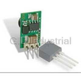
MURATA POWER SOLUTIONS CRE1S2405SC

Description
1 W, 21.6 -26.4 V VIN, SINGLE OUTPUT, 5 V@0.2 A DATACOM/INDUSTRIAL/OEM/COMMERCIAL DC-DC CONVERTER IN STANDARD SIP
Part Number
CRE1S2405SC
Price
Request Quote
Manufacturer
MURATA POWER SOLUTIONS
Lead Time
Request Quote
Category
Capacitors » DC-DC Converter
Specifications
Manufacturer
Murata Power Solutions
Manufacturers Part #
CRE1S2405SC
Series
CRE1
Factory Pack Quantity
35
Application
General Purpose
Connection Type
Through Hole
Dimensions
0.45 x 0.24 x 0.39"
Efficiency
71.00%
Environmental Conditions
General Purpose
Industry
Datacom, Industrial, OEM/Commercial
Input Type
±10%
Input Voltage Nominal
24 V
Isolation
1000 VDC
Mechanical Style
Isolated
Mounting
PCB Mount
Number of Outputs
1
Operating Temperature
-40 to +85°C, no derating
Output Amps 1
0.2 A
Output Voltage V1 Nominal
5 V
Power
1 W
Standard Packaging Size
SIP
Subcategory
DC-DC Converter
Weight
1.09
Datasheet

Extracted Text
CRE1 Series www.murata-ps.com Isolated 1W Single Output Isolated DC-DC Converters SELECTION GUIDE % mV p-p % MIL. Tel. V V mA mA pF Typ. Max. Typ. Max. Min. Typ. kHrs CRE1S0505DC 5 5 200 12 14 16 40 286 65 70 30 CRE1S0505SC 5 5 200 12 14 16 40 286 65 70 30 CRE1S0515SC 5 15 67 6 7.5 10 25 250 77 80 40 FEATURES CRE1S1205SC 12 5 200 8 10 12 30 117 68 71 33 3 UL 60950 recognised n CRE1S1212SC 12 12 83 4 5 8 20 104 75 80 55 CRE1S2405SC 24 5 200 8.5 10 13 30 58 67 71 40 Single Isolated output n CRE1S2412SC 24 12 83 3 4 10 25 52 75 80 78 1kVDC or 3kVDC option ‘Hi Pot Test’ n 3KVDC isolation options CRE1S0305S3C 3.3 5 200 10 12 15 25 400 72 75 35 Wide temperature performance at full n 4 CRE1S0505S3C 5 5 200 6 8 15 25 250 73 77 24 1W load -40°C to 85°C n Surface mount options Industry Standard Pinout n CRE1S0505MC 5 5 200 12.8 15 62 85 294 68 35 6857 CRE1S0505MEC 5 5 200 6.5 8 25 70 239 79 82 22 3041 3.3V, 5V, 12V & 24V Inputs n INPUT CHARACTERISTICS 5V, 12V & 15V outputs n Parameter Conditions Min. Typ. Max. Units Pin Compatible with CME, CRL2, LME, n Continuous operation, 3.3V input types 2.97 3.3 3.63 V MEE1, MEE3, MTE1, NKE, NME, NML & Continuous operation, 5V input types 4.5 5.0 5.5 Voltage range NTE series Continuous operation, 12V input types 10.8 12 13.2 Continuous operation, 24V input types 21.6 24 26.4 Through hole and surface mount options n 3.3V & 12V input types 1 15 available n 5V & 24V input types 2 15 Reflected ripple current mA p-p CRE1S0505MC 30 47 PRODUCT OVERVIEW CRE1S0505MEC 5 15 The CRE1 series are a cost effective 1W DC-DC converter series, in industry standard packages OUTPUT CHARACTERISTICS with industry standard pinout. Popular input Parameter Conditions Min. Typ. Max. Units and output voltages are available. The galvanic 3 Rated Power TA=-40°C to 85°C 1 W isolation allows the device to be configured to Voltage Set Point Accuracy See tolerance envelope provide an isolated negative rail in systems where Line regulation High VIN to low VIN 1.1 1.2 %/% only positive rails exist. The wide temperature range guarantees startup from –40°C and full 1 ISOLATION CHARACTERISTICS 3 watt output at 85°C . Parameter Conditions Min. Typ. Max. Units C Versions Flash tested for 1 second 1000 Isolation test voltage VDC 3C Versions Flash tested for 1 second 3000 Resistance Viso= 1000VDC 10 GΩ GENERAL CHARACTERISTICS Parameter Conditions Min. Typ. Max. Units 3.3V input types 115 5V input types 110 kHz Switching frequency 12V input types 145 24V input types 100 CRE1S0505MEC 80 1. If components are required in tape and reel format suffix order code with -R, e.g. CRE1S0505MC-R. 2. Calculated using MIL-HDBK-217 FN2 and Telcordia SR-332 calculation model with nominal input voltage at full load. 3. UL 60950 recognition does not apply to CRE1S0505MC. 4. 24V input parts prior to date code D1635 have operating temperature range of 0 to 70°C. For full details go to www.murata-ps.com/rohs All specifications typical at TA=25°C, nominal input voltage and rated output current unless otherwise specified. www.murata-ps.com/support KDC_CRE1.D02 Page 1 of 14 1 Order Code Nominal Input Voltage Output Voltage Output Current Load Regulation Ripple & Noise Input Current at Rated Load Efficiency Isolation Capacitance 2 MTTF CRE1 Series Isolated 1W Single Output Isolated DC-DC Converters ABSOLUTE MAXIMUM RATINGS Lead temperature 1.5mm from case for 10 seconds 260°C Input voltage VIN, 3.3V input 5.5V Input voltage VIN, 5V input 7V Input voltage VIN, 12V input 15V Input voltage VIN, 24V input 28V TEMPERATURE CHARACTERISTICS Parameter Conditions Min. Typ. Max. Units 1 -40 85 Specification All output types Storage -50 130 5V output types 41 °C Case temperature rise above All other output types 32 ambient CRE1S0505MC 43 CRE1S0505MEC 12.5 Cooling Free air convection TECHNICAL NOTES ISOLATION VOLTAGE ‘Hi Pot Test’, ‘Flash Tested’, ‘Withstand Voltage’, ‘Proof Voltage’, ‘Dielectric Withstand Voltage’ & ‘Isolation Test Voltage’ are all terms that relate to the same thing, a test voltage, applied for a specified time, across a component designed to provide electrical isolation, to verify the integrity of that isolation. Murata Power Solutions CRE1 series of DC-DC converters are all 100% production tested at their stated isolation voltage. This is 1kVDC for 1 second for C versions and 3kVDC for 1 second for 3C versions. A question commonly asked is, “What is the continuous voltage that can be applied across the part in normal operation?” The CRE1 series, through hole variants (excluding surface mount variants) have been recognised by Underwriters Laboratory for functional insulation, both input and output should normally be maintained within SELV limits i.e. less than 42.4V peak, or 60VDC. The isolation test voltage represents a measure of immunity to transient voltages and the part should never be used as an element of a safety isolation system. The part could be expected to function correctly with several hundred volts offset applied continuously across the isolation barrier; but then the circuitry on both sides of the barrier must be regarded as operating at an unsafe voltage and further isolation/insulation systems must form a barrier between these circuits and any user-accessible circuitry according to safety standard requirements. REPEATED HIGH-VOLTAGE ISOLATION TESTING It is well known that repeated high-voltage isolation testing of a barrier component can actually degrade isolation capability, to a lesser or greater degree depending on materials, construction and environment. The CRE1 series has toroidal isolation transformers, with no additional insulation between primary and secondary windings of enamelled wire. While parts can be expected to withstand several times the stated test voltage, the isolation capability does depend on the wire insulation. Any material, including this enamel (typically polyurethane) is susceptible to eventual chemical degradation when subject to very high applied voltages thus implying that the number of tests should be strictly limited. We therefore strongly advise against repeated high voltage isolation testing, but if it is absolutely required, that the voltage be reduced by 20% from specified test voltage. This consideration equally applies to agency recognized parts rated for better than functional isolation where the wire enamel insulation is always supplemented by a further insulation system of physical spacing or barriers. SAFETY APPROVAL The CRE1 series has been recognised by Underwriters Laboratory (UL) to UL60950 for functional insulation in a maximum still air ambient temperature of 100°C for the C versions and 130°C for the 3C versions as measured on the case of the unit (hotspot). The CRE1S0505MC is not currently UL recognised. The CRE1 series of converters are not internally fused so to meet the requirements of UL60950 an anti-surge input line fuse should always be used with ratings as defined below. CRE1S03xxS3C: 1A CRE1S05xxxxC: 0.7A CRE1S12xxSC: 0.2A CRE1S24xxSC: 0.16A All fuses should be UL recognised, 125V rated. File number E151252 applies. 1. 24V input parts prior to date code D1635 have operating temperature range of 0 to 70°C. www.murata-ps.com/support KDC_CRE1.D02 Page 2 of 14 CRE1 Series Isolated 1W Single Output Isolated DC-DC Converters 1 TEMPERATURE DERATING GRAPH - Surface Mount & 3C types TEMPERATURE DERATING GRAPH - All other types 85°C 85°C 1.0 1.0 Safe Operating Area Safe Operating Area 120°C 0 0 -40 0 50 100 150 -40 0 50 100 150 Ambient Temperature (°C) Ambient Temperature (°C) EFFICIENCY VS LOAD 3.3V Inputs 5V Inputs CRE1S0305S3C 90 90 80 80 70 70 60 60 CRE1S0505XC 50 50 CRE1S0515SC CRE1S0305S3C CRE1S0505S3C 40 40 CRE1S0505MC CRE1S0505MEC 30 30 20 20 10 10 0 0 0 10 20 30 40 50 60 70 80 90 100 0 10 20 30 40 50 60 70 80 90 100 Load (%) Load (%) 12V Inputs 24V Inputs 90 90 80 80 70 70 60 60 CRE1S2405SC 50 50 CRE1S1205SC 40 40 CRE1S2412SC CRE1S1212SC 30 30 20 20 10 10 0 0 0 10 20 30 40 50 60 70 80 90 100 0 10 20 30 40 50 60 70 80 90 100 Load (%) Load (%) 1. 24V input parts prior to date code D1635 have operating temperature range of 0 to 70°C. www.murata-ps.com/support KDC_CRE1.D02 Page 3 of 14 Efficiency (%) Efficiency (%) Output Power (W) Output Power (W) Efficiency (%) Efficiency (%) CRE1 Series Isolated 1W Single Output Isolated DC-DC Converters TOLERANCE ENVELOPES The voltage tolerance envelope shows typical load regulation characteristics for this product series. The tolerance envelope is the maximum output voltage variation due to changes in output loading. CRE1S0505XC CRE1S0515SC 10% 7% 6% 3% 0% 0% -3% -6% 100 100 10 25 50 75 10 25 50 75 Output Load Current (%) Output Load Current (%) CRE1S1205SC CRE1S1212SC 7% 5% 3% 2% 2% 1% -1% -6% 50 75 100 50 75 100 10 25 10 25 Output Load Current (%) Output Load Current (%) CRE1S2405SC CRE1S2412SC 8% 5% 2% 1% 0% -1% -3% -4% 100 100 10 25 50 75 10 25 50 75 Output Load Current (%) Output Load Current (%) www.murata-ps.com/support KDC_CRE1.D02 Page 4 of 14 Output Voltage Output Voltage Output Voltage Output Voltage Output Voltage Output Voltage CRE1 Series Isolated 1W Single Output Isolated DC-DC Converters TOLERANCE ENVELOPES (continued) CRE1S0305S3C CRE1S0505S3C 9% 7% 6% 3% 1% 0% -3% -5% 75 100 10 25 50 75 100 10 25 50 Output Load Current (%) Output Load Current (%) CRE1S0505MC CRE1S0505MEC 10% 7% 3% 3% 2% 0% -4% -8% 10 25 50 75 100 10 25 50 75 100 Output Load Current (%) Output Load Current (%) RoHS COMPLIANCE and MSL INFORMATION The Through Hole parts (SIP/DIP) in this series are compatible with RoHS soldering systems with a peak wave solder temperature of 260°C for 10 seconds. The pin termination finish on the SIP package type is Tin Plate, Hot Dipped over Matte Tin with Nickel Preplate. The DIP types are Matte Tin over Nickel Preplate. This series is backward compatible with Sn/Pb soldering systems. The Surface Mount parts (MC/MEC) in this series are compatible with RoHS soldering systems as per J-STD-020D.1 The pin termination finish on the Surface Mount package types is Matte Tin over Nickel Preplate. This series is backward compatible with Sn/Pb soldering systems. The Surface Mount parts have a Moisture Sensitivity Level (MSL) 1. Samples of the Surface Mount parts were tested in accordance with the conditioning described for MSL level 1 in IDC/J-STD-020D.1. The products passed electrical tests and visual inspection criteria. For further information, please visit www.murata-ps.com/rohs www.murata-ps.com/support KDC_CRE1.D02 Page 5 of 14 Output Voltage Output Voltage Output Voltage Output Voltage CRE1 Series Isolated 1W Single Output Isolated DC-DC Converters APPLICATION NOTES Minimum load The minimum load to meet datasheet specification is 10% of the full rated load across the specified input voltage range. Lower than 10% minimum loading will result in an increase in output voltage, which may rise to typically double the specified output voltage if the output load falls to less than 5%. Capacitive loading and start up Typical start up times for this series, with a typical input voltage rise time of 2.2µs and output capacitance of 10µF, are shown in the table below. The product series will start into a capacitance of 47µF with an increased start time, however, the maximum recommended output capacitance is 10µF. Typical Start-Up Wave Form Start-up time µs CRE1S0505DC 190 CRE1S0505SC 190 CRE1S0515SC 1790 CRE1S1205SC 125 CRE1S1212SC 500 CRE1S2405SC 135 CRE1S2412SC 430 CRE1S0305S3C 295 CRE1S0505S3C 165 CRE1S0505MC 1368 CRE1S0505MEC 170 www.murata-ps.com/support KDC_CRE1.D02 Page 6 of 14 CRE1 Series Isolated 1W Single Output Isolated DC-DC Converters APPLICATION NOTES (continued) Ripple & Noise Characterisation Method Ripple and noise measurements are performed with the following test configuration. C1 1µF X7R m ultilayer ceramic capacitor, voltage rating to be a minimum of 3 times the output voltage of the DC-DC converter 10µF tantalum capacitor, voltage rating to be a minimum of 1.5 times the output voltage of the DC-DC converter with an ESR of less C2 than 100mΩ at 100 kHz C3 100nF multilayer ceramic capacitor, general purpose R1 450Ω resistor, carbon film, ±1% tolerance R2 50Ω BNC termination T1 3T of the coax cable through a ferrite toroid RLOAD Resistive load to the maximum power rating of the DC-DC converter. Connections should be made via twisted wires Measured values are multiplied by 10 to obtain the specified values. DC/DC Converter Differential Mode Noise Test Schematic OSCILLOSCOPE C1 C2 C3 R1 T1 R2 Y INPUT + + Input Output SUPPLY - - R LOAD Output Ripple Reduction By using the values of inductance and capacitance stated, the output ripple at the rated load is lowered to 5mV p-p max. Component selection Capacitor: It is required that the ESR (Equivalent Series Resistance) should be as low as possible, ceramic types are recommended. The voltage rating should be at least twice (except for 15V output), the rated output voltage of the DC-DC converter. Inductor: The rated current of the inductor should not be less than that of the output of the DC-DC converter. At the rated current, the DC resistance of the inductor should be such that the voltage drop across the inductor is <2% of the rated voltage of the DC-DC converter. The SRF (Self Resonant Frequency) should be >20MHz. L DC Power Load C Source DC Inductor Capacitor L, µH SMD Through Hole C, µF CRE1S0505DC CRE1S0505SC CRE1S0515SC CRE1S1205SC CRE1S1212SC CRE1S2405SC CRE1S2412SC CRE1S0305S3C CRE1S0505S3C CRE1S0505MC 47 82473C 11R473C 4.7 CRE1S0505MEC 10 82103C 11R103C 4.7 www.murata-ps.com/support KDC_CRE1.D02 Page 7 of 14 CRE1 Series Isolated 1W Single Output Isolated DC-DC Converters EMC FILTERING AND SPECTRA FILTERING The following table shows the additional input capacitor and input inductor typically required to meet EN 55022 Curve B Quasi-Peak EMC limit, as shown in the following plots. The following plots show positive and negative quasi peak and CISPR22 Average Limit B (pink line) and Quasi Peak Limit B (green line) adherence limits.The below values are for guidance only and should be evaluated in the application circuit. For the CRE1S0505MEC an input inductor is not required. L DC C DC Inductor Capacitor Rated Recommended Part Part Number L, µH SMD Through Hole C, µF Voltage Number CRE1S0505DC 4.7 82472C 13R472C 4.7 16VDC GRM188Z71C475ME21 CRE1S0505SC 4.7 82472C 13R472C 4.7 16VDC GRM188Z71C475ME21 CRE1S0515SC 4.7 82472C 13R472C 4.7 16VDC GRM188Z71C475ME21 CRE1S1205SC 10 82103C 13R103C 1 50VDC GRM21BR71H105KA12 CRE1S1212SC 10 82103C 13R103C 1 50VDC GRM21BR71H105KA12 CRE1S2405SC 22 82223C 13R223C 10 50VDC GRM32ER71H106MA12 CRE1S2412SC 22 82223C 13R223C 10 50VDC GRM32ER71H106MA12 CRE1S0305S3C 10 82103C 13R103C 1 50VDC GRM188R71C105MA12 CRE1S0505S3C 10 82103C 13R103C 1 50VDC GRM188R71C105MA12 CRE1S0505MC 10 82103C 13R103C 4.7 16VDC GRM188Z71C475ME21 CRE1S0505MEC NR NR NR 22 10VDC GRM32ER71A226ME20 NR - Not required CRE1S0505XC CRE1S0515SC 80 80 70 70 60 60 50 50 40 40 30 30 20 20 10 10 0 0 1.00E+05 1.00E+06 1.00E+07 1.00E+08 1.00E+05 1.00E+06 1.00E+07 1.00E+08 Frequency (Hz) Frequency (Hz) CRE1S1205SC CRE1S1212SC 80 80 70 70 60 60 50 50 40 40 30 30 20 20 10 10 0 0 1.00E+05 1.00E+06 1.00E+07 1.00E+08 1.00E+05 1.00E+06 1.00E+07 1.00E+08 Frequency (Hz) Frequency (Hz) www.murata-ps.com/support KDC_CRE1.D02 Page 8 of 14 dBuV dBuV dBuV dBuV CRE1 Series Isolated 1W Single Output Isolated DC-DC Converters EMC FILTERING AND SPECTRA CRE1S2405SC CRE1S2412SC 80 80 70 70 60 60 50 50 40 40 30 30 20 20 10 10 0 0 1.00E+05 1.00E+06 1.00E+07 1.00E+08 1.00E+05 1.00E+06 1.00E+07 1.00E+08 Frequency (Hz) Frequency (Hz) CRE1S0305S3C CRE1S0505S3C 80 80 70 70 60 60 50 50 40 40 30 30 20 20 10 10 0 0 1.00E+05 1.00E+06 1.00E+07 1.00E+08 1.00E+05 1.00E+06 1.00E+07 1.00E+08 Frequency (Hz) Frequency (Hz) CRE1S0505MC CRE1S0505MEC 80 80 70 70 60 60 50 50 40 40 30 30 20 20 10 10 0 0 1.00E+05 1.00E+06 1.00E+07 1.00E+08 1.00E+05 1.00E+06 1.00E+07 1.00E+08 Frequency (Hz) Frequency (Hz) www.murata-ps.com/support KDC_CRE1.D02 Page 9 of 14 dBuV dBuV dBuV dBuV dBuV dBuV CRE1 Series Isolated 1W Single Output Isolated DC-DC Converters PACKAGE SPECIFICATIONS SC Package DC Package 3C Package CRE1S 0505DC XYYWW 11.53±0.2 [0.454±0.008] 11.53±0.2 [0.454±0.008] CRE1S CRE1S XXXXSC 7.46±0.25 [0.294±0.010] 10.00±0.25 [0.394±0.010] XXXXS3C XYYWW XYYWW S S 123 4 4.10±0.5 [0.161±0.020] 1 2 3 4 4.10±0.5 [0.161±0.020] 2.54 [0.100] 0.50±0.05 [0.020±0.002] 2.54 [0.100] 0.50±0.05 [0.020±0.002] 0.25±0.05 [0.010±0.002] (1.95 [0.077]) (2.21 [0.087]) 0.25±0.05 [0 .010±0.002] +0.15 +0.006 +0.15 +0.006 (1.13 [0.044]) 6.10 0.240 (1.13 [0.044]) 6.10 0.240 -0.25 [ -0.010 ] -0.20 [ -0.008 ] All dimensions in mm (inches) Controlling dimension is mm. All pins on a 2.54 (0.100) pitch and within ±0.1 (0.004) of true position from pin 1 at seating plane ‘S’ (SC&3C) All pins on a 2.54 (0.100) pitch and within ±0.25 (0.010) of true position (DC) Weight: 1.09g (3C) 1.30g (SC) 1.38g (DC) PIN CONNECTIONS DC - 8 PIN DIP PIN CONNECTIONS SC & 3C - 4 PIN SIP Pin Function Pin Function 1 -VIN 1 -VIN 4 +VIN 2 +VIN 5 +VOUT 3 -VOUT 7 -VOUT 4 +VOUT www.murata-ps.com/support KDC_CRE1.D02 Page 10 of 14 0.40 [0.016] MIN 0.40 [0.016] MIN CRE1 Series Isolated 1W Single Output Isolated DC-DC Converters PACKAGE SPECIFICATIONS (Continued) CRE1S0505MC CRE1S0505MEC 12.70±0.20 (0.500±0.008) 12.70 (0.500) 7.62 (0.300) 7.62 (0.300) 14 8 DETAIL A 14 8 0.50 (0.020) REFERENCE PLANE 11.00±0.15 10.70±0.15 CRE1S0505MEC CRE1S0505MC (0.433±0.006) (0.421±0.006) P XYYWW XYYWW 1.50 (0.059) 1 3 7 1.20 (0.047) ° ±5.00 10 PINS 0.65 (0.026) 2.54 (0.100) 0.2 (0.008) S 1 3 7 0.55 (0.022) 2.54 (0.100) 0.6±0.05 (0.024±0.002) 2.10 (0.083) DETAIL A 6.60 (0.260) 6.35 (0.250) SEATING 5.95 (0.234) 5.85 (0.230) S PLANE +0.35 +0.014 7.05 ( 0.278 ) -0.10 -0.004 0.30 (0.012) 0.25 (0.010) (1.875 MAX) 2.79 (0.110) MAX 0.10 (0.004) 0.20 (0.008) 0.1(0.004) S 0.25±0.05 (0.010±0.002) 0.2 (0.008) Min. x5 Pins 0.10 S 2.54±0.15 (0.100±0.006) 1.56±0.10 (0.061±0.004) All dimensions in mm (inches) Controlling dimension is mm. All pins on a 2.54 (0.100) pitch and within ±0.25 (0.010) of true position PIN CONNECTIONS - CRE1SXXXXMC/MEC Pin Function 1 -VIN 3 +VIN 7 -VOUT 8 +VOUT 14 NA Weight: 1.2g www.murata-ps.com/support KDC_CRE1.D02 Page 11 of 14 7.70(0.303) 10.90± 0.3 (0.43 ± 0.012) CRE1 Series Isolated 1W Single Output Isolated DC-DC Converters PACKAGE SPECIFICATIONS (continued) RECOMMENDED FOOTPRINT DETAILS DC SC/3C 2.54 [0.100] x4 HOLES 1.15 0.045 Ø Ø 1.00 0.039 [ ] 2.54 [0.100] TUBE OUTLINE DIMENSIONS DC Tube SC Tube 3C Tube 12.0 [0.472] 9.3 [0.366] 7.7 [0.303] 9.3 [0.366] 12.43 [0.489] 14.8 [0.583] 14.5 [0.571] 18.0 [0.709] 5.07±0.80 [0.200±0.03] 5.05 [0.199] 4.45 [0.175] 5.0 [0.197] Unless otherwise specified all dimensions in mm [inches] ±0.55mm [0.022]. Tube Length (DC&SC) : 520mm [20.472] ±2.0 [0.079] T ube Quantity (DC & SC): 35 Tube Length (3C) : 525mm [20.669] ±2.0 [0.079]. (3C):40 www.murata-ps.com/support KDC_CRE1.D02 Page 12 of 14 CRE1 Series Isolated 1W Single Output Isolated DC-DC Converters PACKAGE SPECIFICATIONS (continued) RECOMMENDED FOOTPRINT DETAILS 7.62 (0.3) 2.00 (0.079) 9.70 (0.382) 2.54 (0.1) 1.00 (0.040) MIN TUBE OUTLINE DIMENSIONS CRE1S0505MC CRE1S0505MEC 0.60±0.15 (0.024±0.006) 2.10 (0.083) 14.35 (0.565) 9.40 (0.370) 6.70 (0.264) 9.05 (0.36) Unless otherwise specified all dimensions in mm [inches] ±0.55mm [0.022]. T ube Quantity (MC): 35 Tube Length (MC&MEC) : 475±2.0 (18.70±0.07). (MEC): 30 www.murata-ps.com/support KDC_CRE1.D02 Page 13 of 14 11.40 (0.45) 14.85 (0.59) CRE1S0505MC XYYWW CRE1S0505MEC XYYWW CRE1S0505MC XYYWW CRE1 Series Isolated 1W Single Output Isolated DC-DC Converters TAPE & REEL SPECIFICATIONS REEL OUTLINE DIMENSIONS TAPE OUTLINE DIMENSIONS 330±2.0 (12.99±0.08) 13.25 (0.52) 0.60 (0.02) Max. Ø100 (3.94) +0.004 (+0.10) 1.50 (Ø0.06) -0.00 (-0.00) 16.00 (0.63) 2.00 13.00±0.5 Ø (0.08) (0.51±0.02) 11.50 4.00 (0.45) (0.16) 1.75(0.07) 11.50 (0.45) 24.00±0.30 8.10 (0.94±0.01) (0.32) REEL PACKAGING DETAILS TRAILER SECTION GOODS ENCLOSURE CARRIER TAPE START Product Orientation 160 (6.30) MIN 100 (3.94) MIN SECTION Pin 1, located nearest to carrier drive sprocket. LEADER SECTION Reel Quantity: 500 400 (15.75) MIN This product is subject to the following operating requirements and the Life and Safety Critical Application Sales Policy: Refer to: http://www.murata-ps.com/requirements/ Murata Power Solutions, Inc. makes no representation that the use of its products in the circuits described herein, or the use of other technical information contained herein, will not infringe upon existing or future patent rights. The descriptions contained herein do not imply the granting of licenses to make, use, or sell equipment constructed in accordance therewith. Specifications are subject to change without notice. © 2018 Murata Power Solutions, Inc. www.murata-ps.com/support KDC_CRE1.D02 Page 14 of 14 2.00(+0.08) 24.40 (0.96) (AT HUB SECTION) -0.00(0.00) 30.40(1.20) MAX DIRECTION OF UNREELING
Frequently asked questions
How does Electronics Finder differ from its competitors?

Is there a warranty for the CRE1S2405SC?
Which carrier will Electronics Finder use to ship my parts?
Can I buy parts from Electronics Finder if I am outside the USA?
Which payment methods does Electronics Finder accept?
Why buy from GID?

Quality
We are industry veterans who take pride in our work

Protection
Avoid the dangers of risky trading in the gray market

Access
Our network of suppliers is ready and at your disposal

Savings
Maintain legacy systems to prevent costly downtime

Speed
Time is of the essence, and we are respectful of yours
Related Products
DC/DC 8-36VIN/3.3VOUT .5A SIP 7803SR-C
DC/DC 8-36VIN/3.3VOUT .5A HSIP 7803SRH-C
DC/DC 8-36VIN/5VOUT .5A SIP 7805SR-C
DC/DC 8-36VIN/5VOUT .5A HSIP 7805SRH-C
4.8 W, 15 -36 VDC VIN, SINGLE OUTPUT, 12 VDC@0.4 A DC-DC CONVERTER 7812SR-C
4.8 W, 15 -36 VDC VIN, SINGLE OUTPUT, 12 VDC@0.4 A DC-DC CONVERTER 7812SRH-C
Request a Quote

The quote request has been received
Close

Facing challenges or have inquiries? Feel free to contact us!
Call Us +1-469-283-2440
What they say about us
FANTASTIC RESOURCE
One of our top priorities is maintaining our business with precision, and we are constantly looking for affiliates that can help us achieve our goal. With the aid of GID Industrial, our obsolete product management has never been more efficient. They have been a great resource to our company, and have quickly become a go-to supplier on our list!
Bucher Emhart Glass
EXCELLENT SERVICE
With our strict fundamentals and high expectations, we were surprised when we came across GID Industrial and their competitive pricing. When we approached them with our issue, they were incredibly confident in being able to provide us with a seamless solution at the best price for us. GID Industrial quickly understood our needs and provided us with excellent service, as well as fully tested product to ensure what we received would be the right fit for our company.
Fuji
HARD TO FIND A BETTER PROVIDER
Our company provides services to aid in the manufacture of technological products, such as semiconductors and flat panel displays, and often searching for distributors of obsolete product we require can waste time and money. Finding GID Industrial proved to be a great asset to our company, with cost effective solutions and superior knowledge on all of their materials, it’d be hard to find a better provider of obsolete or hard to find products.
Applied Materials
CONSISTENTLY DELIVERS QUALITY SOLUTIONS
Over the years, the equipment used in our company becomes discontinued, but they’re still of great use to us and our customers. Once these products are no longer available through the manufacturer, finding a reliable, quick supplier is a necessity, and luckily for us, GID Industrial has provided the most trustworthy, quality solutions to our obsolete component needs.
Nidec Vamco
TERRIFIC RESOURCE
This company has been a terrific help to us (I work for Trican Well Service) in sourcing the Micron Ram Memory we needed for our Siemens computers. Great service! And great pricing! I know when the product is shipping and when it will arrive, all the way through the ordering process.
Trican Well Service
GO TO SOURCE
When I can't find an obsolete part, I first call GID and they'll come up with my parts every time. Great customer service and follow up as well. Scott emails me from time to time to touch base and see if we're having trouble finding something.....which is often with our 25 yr old equipment.
ConAgra Foods