

 Manufacturers
MURATA POWER SOLUTIONS D1U54P-W-450-12-HA3C

Description
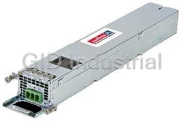
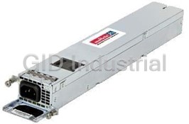
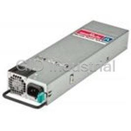
450 W, SINGLE OUTPUT, 12 VDC@37.5 A AC-DC POWER SUPPLY
Part Number
D1U54P-W-450-12-HA3C
Price
Request Quote
Manufacturer
MURATA POWER SOLUTIONS
Lead Time
Request Quote
Category
Circuit Protection » AC-DC Power Supply
Specifications
Manufacturer
Murata Power Solutions
Manufacturers Part #
D1U54P-W-450-12-HA3C
Industry Aliases
Series
D1U54P-W-450-12-HxxC
Factory Pack Quantity
25
Cooling Method
Air-Cooled
Dimensions
9.00 x 2.15 x 1.57"
Efficiency
91%
Input Voltage Nominal
240 VAC, 100 VAC
Isolation
3000 VAC
Mechanical Style
PFC Front End
Mounting
Chassis
Number of Outputs
1
Operating Temperature
- 5 to + 50°C
Output Amps 1
37.5 A
Output Voltage V1 Nominal
12 VDC
Power
450 W
Subcategory
AC-DC Power Supply
Datasheet

Extracted Text
D1U54P-W-450-12-HxxC Series 54mm 1U Front End AC-DC Power Supply Converter PRODUCT OVERVIEW The D1U54P-W-450-12-HAxC series power modules are very high efficiency, 450 watt power factor corrected front end supplies, with a 12Vdc main output and standby output. An active (digital) current share characteristic is provided to allow units to operate in parallel and share load current. The power supply may be hot plugged; recovers from overtemperature faults, and has status LEDs on the front panel in addition to hardware signal logic and PMBus™ status signals. The low profile 1U package and 14.8W/cubic inch power density make them ideal for delivering reliable, efficient power to networking equipment, workstations, storage systems and other 12Vdc distributed power architectures. ORDERING GUIDE Power Output Main Standby Part Number Airflow 90-264Vac Output Output D1U54P-W-450-12- HA3C 5Vdc Front to Back D1U54P-W-450-12- HB3C 12Vdc 450W 12Vdc D1U54P-W-450-12- HA4C 5Vdc Back to front D1U54P-W-450-12- HB4C 12Vdc FEATURES INPUT CHARACTERISTICS 450W output power Parameter Conditions Min. Nom. Max. Units 12Vdc main output Input Source Voltage 90 100/240 264 Vac 5Vdc & 12Vdc standby output options Input Source 47 50/60 63 Hz <1U height: Turn-on Input Ramp up 74 84 Vac 54.5mm x 228.6mm x 40mm Turn-off Input Ramp down 70 80 Maximu m current at 450W; 100-240Vac 6 Arms (2.15" x 9.0" x 1.57") Inrus h Current Cold start between 0 to Card Edge DC Output and Signal I/O Connector 20 Apk 200msec IEC 60320-C14 AC Inlet At 230Vac, 100% load 0.96 14.8 Watts per cubic inch density Power Factor W/VA At 230Vac, 50% load 0.95 N+1 redundancy capable At 230Vac 20% load 90 Active (digital) current sharing on 12Vdc main Efficiency At 230Vac 50% load 94 % output; both outputs include ORING FET circuit At 230Vac 100% load 91 Overvoltage, Overcurrent, Overtemperature protection OUTPUT VOLTAGE CHARACTERISTICS Internal cooling fan (variable speed) Nominal PMBus™/I2C interface with status indicators Output Parameter Conditions Min. Typ. Max. Units RoHS compliant Voltage Output Set Point Accuracy 50% load; Tamb =25°C 11.96 12.00 12.04 Vdc Two Year Warranty Setpoint; temperature; line 2 Line and Load Regulation -1.0% +1.5 % and load 1, 2 Ripple Voltage & Noise 20MHz Bandwidth 120 mV p-p 12V Output Current Range 0 37.5 A Load Capacitance 500 4000 μF Nominal Output Voltage 5.0 3 Line and Load Regulation 4.76 5.24 Vdc 13 5VSB Ripple Voltage & Noise 20MHz Bandwidth 75 mV p-p Output Current 0 2 A Load Capacitance 250 1000 μF Nominal Output Voltage 12.0 3 Line and Load Regulation 11.7 12.3 Vdc 13 12VSB Ripple Voltage & Noise 20MHz Bandwidth 120 mV p-p Output Current 0 1 A Load Capacitance 250 1000 μF 1 Ripple and noise are measured with 0.1 μF of ceramic capacitance and 10 μF of tantalum capacitance on each of the power supply Available now at: outputs. A short coaxial cable to the measurement ‘scope input, is used. www.murata-ps.com/en/3d/acdc.html 2 Minimum Load of 1.75A 3 Minimum load of 0.28A Certificate and Test Report www.murata-ps.com/support D1U54P-W-450-12-HXXC.A04 Page 1 of 9 D1U54P-W-450-12-HxxC Series 54mm 1U Front End AC-DC Power Supply Converter OUTPUT CHARACTERISTICS Parameter Conditions Min. Typ. Max. Units Startup Time AC ramp up 3 s Current sharing accuracy (main 12Vdc output) > 10% load (* % total Current) -5 +5 * % Load step of 50% max. load, > 2.5A load, -5 +5 % Transient Response (Single transient, main 12Vdc output) 1A/μs slew rate Recovery Time to within 1% Vnom 2 ms Load step of 50% max. load, > 10% Max -5 +5 % Transient Response (Single transient, Standby output) load load, 1A/μs slew rate Recovery Time to within 1% Vnom 2 ms -5 Hot Swap Transients +5 % Full AC Input Source Range; 100% load 12 ms Holdup Time (Total Effective Hold Up - See Timing Waveforms) ENVIRONMENTAL CHARACTERISTICS Parameter Conditions Min. Typ. Max. Units Storage Temperature Range -40 70 °C Operating Temperature Range 90V-264Vac, 450W -5 50 5 90 Operating Humidity Noncondensing; +45°C % Storage Humidity 5 95 Altitude (without derating at 40°C) 3000 m Acoustic noise levels 25°C, 50%load 45 50 dB Shock 30G non-operating Sine sweep; 5-200Hz, 2G; Operational Vibration random vibration, 5-500Hz, 1.11G Per Telcordia SR-332 Issue 3 M1C3 at MTBF (Target) 520K hrs 40°C CAN/CSA C22.2 No 60950-1: 2007, A2: 2014 UL 60950-1-2014 IEC60950-1:2005+A2:2013 EN 60950-1:2006+A2:2013 Safety Approval Standards (Planned; Pending Submission) BSMI: CNS14336-1 (1999/09/30), CNS13438 (1995/06/01) CCC: GB4943.1-2011; GB/T9254-2008; GB17625.1-2012 Input Fuse Power Supply has internal 8A/250V fast blow fuse on the AC line input Weight 1.51 lbs (0.685 kg) PROTECTION CHARACTERISTICS Output Parameter Conditions Min. Typ. Max. Units Overtemperature (intake) Autorestart with 4°C hysteresis for recovery (warning issued at 70°C) 75 °C 13.0 14.5 Vdc Overvoltage Latching The output shall shutdown when an overcurrent condition is detected. It will auto restart after 1sec; however if the overcurrent condition is redetected the output will 12V once again shutdown. The output will once again re-start, however if the overcurrent condition 40 50 Adc Overcurrent (target) persists it will latch of after the fifth unsuccessful attempt. To reset the latch it will be necessary to toggle the PS_ON_L signal or recycle the incoming DC source. Overvoltage Latching 5.4 6.0 Vdc The output shall shutdown when an overcurrent is detected. 5VSB It will auto restart after 2sec; however if the overcurrent is re-detected the output will once Overcurrent 2.1 3.0 Adc again shutdown. This cycle will occur indefinitely while the overcurrent condition persists. Over-Voltage Latching; toggle PS_ON or recycle DC input to reset 13.0 14.5 Vdc The output shall shutdown when an overcurrent is detected. 12VSB It will auto restart after 2sec; however if the overcurrent is re-detected the output will once Over-Current 1.2 2 Adc again shutdown. This cycle will occur indefinitely while the overcurrent condition persists www.murata-ps.com/support D1U54P-W-450-12-HXXC.A04 Page 2 of 9 D1U54P-W-450-12-HxxC Series 54mm 1U Front End AC-DC Power Supply Converter ISOLATION CHARACTERISTICS Parameter Conditions Min. Typ. Max. Units Input to Output - Reinforced 3000 Vrms Insulation Safety Rating Input to Chassis - Basic 1500 Vrms Isolation Output to Chassis 500 Vdc EMISSIONS AND IMMUNITY Characteristic Standard Compliance Input Current Harmonics IEC/EN 61000-3-2 Complies Voltage Fluctuation and Flicker IEC/EN 61000-3-3 Complies FCC 47 CFR Part 15 Conducted Emissions Class A with 6dB margin CISPR 22/EN55022 ESD Immunity IEC/EN 61000-4-2 Level 4 criteria A Radiated Field Immunity IEC/EN 61000-4-3 Level 3 criteria B Electrical Fast Transients/Burst Immunity IEC/EN 61000-4-4 Level 3 criteria A 1 1. EN61000-4-5, Lev. 3 (Com. Mode: 2kV, 12Ω, Diff. Mode: 1kV, 2Ω), criteria A Surge Immunity IEC/EN 61000-4-5 1 2. GR-1089-CORE (NEBS) Level 1 Table 4-30 (Com/Diff. Mode: 2kV, 2Ω) RF Conducted Immunity IEC/EN 61000-4-6 Level 3 criteria A Magnetic Field Immunity IEC/EN 61000-4-8 3 A/m criteria B 230Vin, 80% load, Phase 0°, Dip 100% Duration 10ms (A) 230Vin, 50% load, Phase 0°, Dip 100% Duration 20ms (VSB:A, V1:B) Voltage Dips, Interruptions IEC/EN 61000-4-11 230Vin, 100% load, Phase 0°, Dip 100% Duration > 20ms (VSB, V1:B) 1 tests are performed at 50% maximum load, and with minimum capacitance at both outputs STATUS INDICATORS AND CONTROL SIGNALS INPUT LED Condition LED Status Input Voltage Present Solid Green Input Voltage fault or warning Blinking Green Input off Off POWER LED Condition LED Status Fault concurrent indication via PMBus Status_x registers Solid Amber Warning, concurrent indication via PMBus Status_x registers Blinking Amber Standby, 12Vdc Main output off, Vstby On Blinking Green Power Good 12Vdc Main output on, Vstby On Solid Green Power Off 12Vdc Main output off, Vstby Off Off www.murata-ps.com/support D1U54P-W-450-12-HXXC.A04 Page 3 of 9 D1U54P-W-450-12-HxxC Series 54mm 1U Front End AC-DC Power Supply Converter STATUS AND CONTROL SIGNALS Signal Name I/O Description Interface Details Pulled up internally via 10K to VDD*. The signal output is driven high when input source is available and within acceptable limits. The output is driven low to indicate loss of input power. A logic high >2.0Vdc INPUT_OK (AC Source) Output There is a minimum of 1ms pre-warning time before the signal is driven low prior to the PWR_OK A logic low <0.8Vdc Link to connector pin signal going low. The power supply must ensure that this interface signal provides accurate status Driven low by internal CMOS buffer when AC power is lost. (open drain output). The signal is asserted, driven high, by the power supply to indicate that the main output is valid. Pulled up internally via 10K to VDD*. Should a main output or standby output fault occur, the PW_OK signal will de-assert + driven low. 5V A logic high >2.0Vdc PW_OK (Output OK) Output & 3.3V Standby output products do not de-assert the PW_OK signal during OCP event on the standby A logic low <0.8Vdc Link to connector pin output. Driven low by internal CMOS buffer PW_OK output is driven low to indicate that the Main output is outside of lower limit of regulation. (open drain output). The signal output is driven low to indicate that the power supply has detected a warning or fault and Pulled up internally via 10K to VDD*. SMB_ALERT is intended to alert the system. This output must be driven high when the power is operating A logic high >2.0Vdc correctly (within specified limits). (FAULT/WARNING) Output A logic low <0.8Vdc Link to connector pin The signal will revert to a high level when the warning/fault stimulus (that caused the alert) is Driven low by internal CMOS buffer removed. As reported by PMBus Status_x Registers, with exception of Status_CML. (open drain output). PRESENT_L Passive connection to +VSB_Return. The signal is used to detect the presence (installation) of a PSU by the host system. The signal is (Power Supply Absent) Output A logic low <0.8Vdc connected to PSU logic +VSB_Return within the power module. Link to connector pin This signal is pulled up internally to the internal housekeeping supply (within the power supply). The Pulled up internally via 10K to VDD*. PS_ON power supply main 12Vdc output will be enabled when this signal is pulled low to +VSB_Return. A logic high >2.0Vdc (Power Supply In the low state the signal input shall not source more than 1mA of current. The 12Vdc output will be Input A logic low <0.8Vdc Enable/Disable disabled when the input is driven higher than 2.4V, or open circuited. Cycling this signal shall clear Input is via CMOS Schmitt trigger Link to connector pin latched fault conditions. buffer. Pulled up internally via 10K to VDD*. This signal is used during hot swap to disable the main output during hot swap extraction. The input is A logic high >2.0Vdc PS_KILL Input pulled up internally to VDD* (within the power supply). A logic low <0.8Vdc Link to connector pin The signal is provided on a short (lagging pin) and should be connected to +VSB_Return. Input is via CMOS Schmitt trigger buffer. An analog input that is used to set the address of the internal slave devices (EEPROM and ADDR (Address Select) microprocessor) used for digital communications. DC voltage between the limits of 0 and Input Connection of a suitable resistor to +VSB_Return, in conjunction with an internal resistor divider +3.3Vdc. Link to connector pin chain, will configure the required address. See configuraiton table for details. TM A serial clock line compatible with PMBus Power Systems Management Protocol Part 1 – General ** VIL is 0.8V maximum Requirements Rev 1.1. VOL is 0.4V maximum when sinking SCL (Serial Clock) Both No additional internal capacitance is added that would affect the speed of the bus. 3mA Link to connector pin The signal is provided with a series isolator device to disconnect the internal power supply bus in the VIH is 2.1V minimum event that the power module is unpowered, TM ** VIL is 0.8V maximum A serial data line compatible with PMBus Power Systems Management Protocol Part 1 – General VOL is 0.4V maximum when sinking SDA (Serial Data) Requirements Rev 1.1. Both 3mA Link to connector pin The signal is provided with a series isolator device to disconnect the internal power supply bus in the VIH is 2.1V minimum event that the power module is unpowered, Remote sense connections intended to be connected at and sense the voltage at the point of load. The voltage sense will interact with the internal module regulation loop to compensate for voltage drops due to connection resistance between the output connector and the load. Compensation for a up to 0.12Vdc V1_SENSE Input If remote sense compensation is not required then the voltage can be configured for local sense total connection drop (output and V1SENSE_RTN by: return connections). 1. V1_SENSE directly connected to power gold fingers P1-P8 (inclusive) 2. V1_SENSE_RTN directly connected to gold fingers P9 to P16 (inclusive) The current sharing signal is connected between sharing units (forming an ISHARE bus). It is an input and/or an output (bi-directional analog bus) as the voltage on the line controls the current Bi- share between sharing units. ISHARE Analogue voltage: Directional A power supply will respond to a change in this voltage but a power supply can also change the Link to connector pin +8V maximum; 10K to +12V_RTN Digital Bus voltage depending on the load drawn from it. On a single unit the voltage on the pin (and the common ISHARE bus would read 8VDC at 100% load (module capability). For two identical units sharing the same 100% load this would read *VDD is an internal voltage rail derived from VSB and an internal housekeeping rail (“diode ORed”) and is compatible with the voltage tolerances of VSB). **For robust PMBus communications, it is recommended SDA and SCA lines be pulled up via external resistors to a voltage of 3.3V or greater. www.murata-ps.com/support D1U54P-W-450-12-HXXC.A04 Page 4 of 9 D1U54P-W-450-12-HxxC Series 54mm 1U Front End AC-DC Power Supply Converter TIMING SPECIFICATIONS Turn-On Delay & Output Rise Time: 1. The turn-on delay after application of AC input within the operating range shall as defined in the following tables. 2. The output rise times shall be measured from 10% of the nominal output to the lower limit of the regulation band as defined in the following tables. Time Min Max Vsb Rise time - 10ms V1 Rise time 6ms 60ms Vsb Power-on-delay - 2700ms V1 Power-on-delay - 3000ms V1 PS_ON delay 100ms 150ms V1 PWOK delay 100ms 300ms ACOK detect 300ms 1500ms TIMING SPECIFICATIONS Turn-Off (Shutdown by PS_ON) Turn-Off Timing Min Max Notes V1 Fall time - - Must be monotonic V1 PS_OFF delay - 10ms PW_OK delay off 1ms - 1. Note this characteristic is applicable for the main 12Vdc output shutdown from PS_ON pulled high. www.murata-ps.com/support D1U54P-W-450-12-HXXC.A04 Page 5 of 9 D1U54P-W-450-12-HxxC Series 54mm 1U Front End AC-DC Power Supply Converter TIMING SPECIFICATIONS Power Removal Holdup Power Removal Timing Min Max Notes Vsb holdup 40ms 2S 100% load V1 holdup (Effective Total) 12ms - 100% load Input fail detect 5ms 11ms 100% load PWOK delay off 1ms - 100% load PWOK Hold Up 11ms - 100% load OUTPUT CONNECTOR & SIGNAL INTERFACE Gold Finger Layout & Pin Assignment Mating Connector: FCI 10126933080820xALF; “Straddle” Connector Top Side Bottom Side P13-P16 P1-P4 P1 P16 P11-P12 P5-P6 P9-P10 P7-P8 P8 P9 S20 S1 Representative View: S10 S11 Notes: Gold Fingers S9 (PS_KILL) and S12 (PS PRESENT/L) are “last to make; fist to break” short pins. For illustraiton purposes only, actual product may appear different. Dimensions as follows: W www.murata-ps.com/support D1U54P-W-450-12-HXXC.A04 Page 6 of 9 D1U54P-W-450-12-HxxC Series 54mm 1U Front End AC-DC Power Supply Converter OUTPUT CONNECTOR PIN ASSIGNMENTS - D1U54P-W-450-12-HBxC; TO BE CONFIRMED (Power Supply Gold Finger/Card Pin# Signal Name Description/Comment P1-P8 inclusive V1 (+12VOUT) +12Vdc Main Output P9-P16 inclusive +12Vdc Main Output and Standby Output Return V1 (+12VOUT) RTN/PGND) S1 +VSB Standby Output S2 +VSB Standby Output S3 Reserved No User Connection S4 ISHARE Active Current Share Bus; link back to signal definition 2 S5 SDA I C Serial Data Line; link back to signal definition 2 S6 SCL I C Serial Clock Line; link back to signal definition S7 SMB_ALERT Alert signal to host system; link back to signal definition S8 PS_ON Remote On/Off (Enable/Disable) ; link back to signal definition S9 PS_KILL Power Supply “kill”; short pin ; link back to signal definition S10 INPUT_OK AC Input Source Present & “OK” ; link back to signal definition S11 PW_OK Output DC Power “OK”; link back to signal definition S12 PS PRESENT Power Module Present; short pin; link back to signal definition S13 Reserved No User Connection S14 Reserved No User Connection S15 V1_SENSE_RTN +12Vdc Main Output Remote Sense Return S16 V1_SENSE +12Vdc Main Output Remote Sense Address Protocol Selection; (select address by use of the appropriate pull down resistor – see table below) ; link back to S17 ADDR signal definition S18 Reserved No User Connection S19 +VSB Standby Output S20 +VSB Standby Output IRIN ADDR ADDRESS SELECTION ADDR pin (A3) resistor to Power Supply Main Controller Power Supply External EEPROM GND (K-ohm)* (Serial Communications Slave Address) (Serial Communications Slave Address) 0.82 0xB0 0xA0 2.7 0xB2 0xA2 5.6 0xB4 0xA4 8.2 0xB6 0xA6 15 0xB8 0xA8 27 0xBA 0xAA 56 0xBC 0xAC 180 0xBE 0xAE * The resistor shall be +/-5% tolerance Link back to Address Definition G DIAGRAM FOR OUTPUT www.murata-ps.com/support D1U54P-W-450-12-HXXC.A04 Page 7 of 9 D1U54P-W-450-12-HxxC Series 54mm 1U Front End AC-DC Power Supply Converter WIRING DIAGRAM FOR OUTPUT CURRENT SHARE NOTES 1. Main Output: Current sharing is achieved using the active current share method details.) 2. Current sharing can be achieved with or without the remote (V_SENSE) connected to the common load. 3. +VSB Outputs can be tied together for redundancy but total combined output power must not exceed the rated standby power. The +VSB output has an internal ORING MOSFET for additional redundancy/internal short protection. 4. The current sharing pin B5 is connected between sharing units (forming an ISHARE bus). It is an input and/or an output (bi-directional analog bus) as the voltage on the line controls the current share between sharing units. A power supply will respond to a change in this voltage but a power supply can also change the voltage depending on the load drawn from it. On a single unit the voltage on the pin (and the common ISHARE bus would read 8VDC at 100% load. For two units sharing the same load this would read 4VDC for perfect current sharing (i.e. 50% load per unit). 5. The load for both the main 12Vdc and the VSB rails at initial startup shall not be allowed to exceed the capability of a single unit. The load can be increased after a delay of 3sec (minimum), to allow all sharing units to achieve steady state regulation. www.murata-ps.com/support D1U54P-W-450-12-HXXC.A04 Page 8 of 9 D1U54P-W-450-12-HxxC Series 54mm 1U Front End AC-DC Power Supply Converter Mechanical Envelope Front to Back Airflow D1U54P-W-450-12- Hx3C Back to Front Airflow D1U54P-W-450- 12- Hx4C Shown for illustration purposes only. Refer to card edge details on Pg. 6 of this datasheet for details 1. Reference file: I:\Eng_wip\UserPDDwg\1909\M1909_Drawing for Product Datasheet_20170407 2. For illustration purposes of the envelope and main features only. Not all details visible on actual product are represented. 3D model is available upon request. 3. Dimensions are in mm Link Back to Features OPTIONAL ACCESSORIES Description Part Number 12Vdc D1U54P 450W series Output Connector Card D1U54P-12-EDGE APPLICATION NOTES Document Number Description Link ACAN-72 D1U54P-x Communication Protocol http://power.murata.com/datasheet?/data/apnotes/acan-72.pdf ACAN-73 Output Connector Card with edge connector http://power.murata.com/datasheet?/data/apnotes/acan-73.pdf This product is subject to the following operating requirements and the Life and Safety Murata Power Solutions, Inc. Critical Application Sales Policy: Refer to: http://www.murata-ps.com/requirements/ 11 Cabot Boulevard, Mansfield, MA 02048 -1151 U.S.A. Murata Power Solutions, Inc. makes no representation that the use of its products in the circuits described herein, or the use of other technical information contained herein, will not infringe upon existing or future patent rights. The descriptions contained herein do not imply the granting of licenses to make, use, or ISO 9001 and 14001 REGISTERED sell equipment constructed in accordance therewith. Specifications are subject to change without notice.© 2016 Murata Power Solutions, Inc. www.murata-ps.com/support D1U54P-W-450-12-HXXC.A04 Page 9 of 9
Frequently asked questions
How does Electronics Finder differ from its competitors?

Is there a warranty for the D1U54P-W-450-12-HA3C?
Which carrier will Electronics Finder use to ship my parts?
Can I buy parts from Electronics Finder if I am outside the USA?
Which payment methods does Electronics Finder accept?
Why buy from GID?

Quality
We are industry veterans who take pride in our work

Protection
Avoid the dangers of risky trading in the gray market

Access
Our network of suppliers is ready and at your disposal

Savings
Maintain legacy systems to prevent costly downtime

Speed
Time is of the essence, and we are respectful of yours
Related Products
400 W, SINGLE OUTPUT, 12 VDC@33.3 A OEM/COMMERCIAL ENCLOSED AC-DC POWER SUPPLY
400 W, SINGLE OUTPUT, 12 VDC@33.3 A OEM/COMMERCIAL ENCLOSED AC-DC POWER SUPPLY
1200 W, SINGLE OUTPUT, 12 VDC@98.3 A AC-DC POWER SUPPLY
1200 W, SINGLE OUTPUT, 12 VDC@98.3 A AC-DC POWER SUPPLY
1200 W, Single Output, 12 VDC@98.3 A AC-DC Power Supply
1200 W, Single Output, 12 VDC@98.3 A AC-DC Power Supply
Request a Quote

The quote request has been received
Close

Facing challenges or have inquiries? Feel free to contact us!
Call Us +1-469-283-2440
What they say about us
FANTASTIC RESOURCE
One of our top priorities is maintaining our business with precision, and we are constantly looking for affiliates that can help us achieve our goal. With the aid of GID Industrial, our obsolete product management has never been more efficient. They have been a great resource to our company, and have quickly become a go-to supplier on our list!
Bucher Emhart Glass
EXCELLENT SERVICE
With our strict fundamentals and high expectations, we were surprised when we came across GID Industrial and their competitive pricing. When we approached them with our issue, they were incredibly confident in being able to provide us with a seamless solution at the best price for us. GID Industrial quickly understood our needs and provided us with excellent service, as well as fully tested product to ensure what we received would be the right fit for our company.
Fuji
HARD TO FIND A BETTER PROVIDER
Our company provides services to aid in the manufacture of technological products, such as semiconductors and flat panel displays, and often searching for distributors of obsolete product we require can waste time and money. Finding GID Industrial proved to be a great asset to our company, with cost effective solutions and superior knowledge on all of their materials, it’d be hard to find a better provider of obsolete or hard to find products.
Applied Materials
CONSISTENTLY DELIVERS QUALITY SOLUTIONS
Over the years, the equipment used in our company becomes discontinued, but they’re still of great use to us and our customers. Once these products are no longer available through the manufacturer, finding a reliable, quick supplier is a necessity, and luckily for us, GID Industrial has provided the most trustworthy, quality solutions to our obsolete component needs.
Nidec Vamco
TERRIFIC RESOURCE
This company has been a terrific help to us (I work for Trican Well Service) in sourcing the Micron Ram Memory we needed for our Siemens computers. Great service! And great pricing! I know when the product is shipping and when it will arrive, all the way through the ordering process.
Trican Well Service
GO TO SOURCE
When I can't find an obsolete part, I first call GID and they'll come up with my parts every time. Great customer service and follow up as well. Scott emails me from time to time to touch base and see if we're having trouble finding something.....which is often with our 25 yr old equipment.
ConAgra Foods